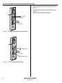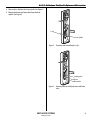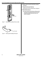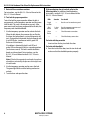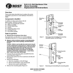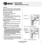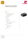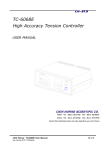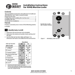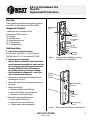
1
B.A.S.I.S. Exit Hardware Trim
Shear Pin
Replacement Kit Instructions
Overview
These instructions describe how to replace the shear pin
in your B.A.S.I.S. Exit Hardware Trim (EXG or EXBV).
Mounting
plate
Components checklist
In addition to these instructions, this kit
(part number 1879013) contains:
❑ 1 Shear pin
❑ 4 Shoulder screws
❑ 5 mounting plate screws
❑ 1 Lift finger screw
❑ 1 Escutcheon gasket
Mounting
standoffs
Escutcheon
gasket
Screw
Lift finger
Tasks to perform
A Remove the escutcheon from door
For instructions, see the B.A.S.I.S. G Service Manual
(T63300) or the B.A.S.I.S. V Service Manual (T61805).
Mounting
standoffs
B Remove internal components
Caution: Before you handle the electronics board
or any component connected to it, make sure that
you are properly grounded using an electrostatic
discharge (ESD) protection kit! Touching the
board without proper grounding can damage
sensitive electronics components—even if you
don’t notice any static discharge!
1 Unscrew the six mounting plate standoffs from the
mounting plate (Figure 1).
2 Remove the gasket from the escutcheon and discard
the gasket.
3 Remove the lift finger:
a Note the orientation of the lift finger.
b Remove the lift finger screw and discard.
c Remove the washer and lift finger.
4 Remove the mounting plate (Figure 2):
a Cut the cable tie and discard.
b Remove the five screws and discard.
c Carefully remove the mounting plate.
Figure 1
Removing and reinstalling the mounting
standoffs, gasket, and lift finger
Primary
harness
Cable tie
Mounting plate
screws
Slot
Mounting
plate
Mounting plate
screws
Figure 2
BEST ACCESS SYSTEMS
Indianapolis, Indiana
Removing and reinstalling the mounting plate
1
B.A.S.I.S. Exit Hardware Trim Shear Pin Replacement Kit Instructions
5 Remove the lever return springs from the yoke. See
Figure 3.
6 Unscrew the four shoulder screws and discard. See
Figure 4.
7 Remove the yoke from the escutcheon.
Lever return
springs
Yoke
Figure 3
Removing and reinstalling lever return springs
Shoulder screws
Yoke
Shoulder screws
Figure 4
2
Removing and reinstalling the yoke
BEST ACCESS SYSTEMS
Indianapolis, Indiana
B.A.S.I.S. Exit Hardware Trim Shear Pin Replacement Kit Instructions
8 Remove the c-clip from the lever spindle. See Figure 5.
9 Remove the beam and beam roller from the lever
spindle. See Figure 6.
C-clip
Lever spindle
Figure 5
Removing and reinstalling the c-clip
Locking plate
Beam
Beam roller
Figure 6
BEST ACCESS SYSTEMS
Indianapolis, Indiana
Removing and reinstalling the beam and beam
roller
3
B.A.S.I.S. Exit Hardware Trim Shear Pin Replacement Kit Instructions
10 Remove the lever from the front of the escutcheon.
See Figure 7.
C Remove the shear pin from lever
■ Remove the shear pin from the lever. See Figure 8.
D Reinstall the shear pin
■ Insert the shear pin into the lever, making sure that
the shear pin is positioned in the lever so that the
head faces the opposite direction of the lever
handle. See Figure 8.
Lever
Figure 7
Removing and reinstalling the lever assembly
Shear pin
Figure 8
4
Removing and reinstalling the shear pin
BEST ACCESS SYSTEMS
Indianapolis, Indiana
B.A.S.I.S. Exit Hardware Trim Shear Pin Replacement Kit Instructions
E Reinstall internal components
1 Make sure that the shear pin is positioned on the lever
so that the head faces the opposite direction of the
lever handle. See Figure 8.
2 Insert the lever through the escutcheon, positioning
the lever so its handle will point toward the door
hinges.
3 Place the beam on the lever spindle so that the slot in
the beam aligns with the locking plate. See Figure 6.
4 Reinstall the c-clip onto the lever spindle. The
orientation of the clip does not matter. See Figure 5.
5 Place the beam roller on the beam.
6 Position the yoke in the escutcheon with the threaded
nut down.
7 Apply Lubriplate GR-132® grease or an equivalent
quality petroleum around the slots on the face of the
yoke.
8 Tightly secure the yoke to the escutcheon using the
four new shoulder screw (20–25 lbs torque). See
Figure 4.
9 Install the lever return springs onto the yoke posts. See
Figure 3.
10 With posts on the mounting plate inserted in the lever
return springs, slide the mounting plate into the
escutcheon (Figure 3). Make sure that the locking plate
fits into the slot in the mounting plate. Secure with the
five new screws. Route the primary harness against the
mounting plate post and secure the harness to the
post with a cable tie. See Figure 2.
11 Position the lift finger on the escutcheon in the
orientation noted in step 3a on page 1.
12 Position the washer on the lift finger screw. Tightly
secure the lift finger with the lift finger screw (25–30
foot-pounds of torque) (Figure 1).
13 Starting at the bottom of the gasket, peel away the
protective backing a small amount at a time while
unrolling the gasket into position on the escutcheon.
Press the gasket into place.
14 Screw the six mounting standoffs onto the mounting
plate (Figure 1).
BEST ACCESS SYSTEMS
Indianapolis, Indiana
5
B.A.S.I.S. Exit Hardware Trim Shear Pin Replacement Kit Instructions
F Reinstall the escutcheon on door
For instructions, see the B.A.S.I.S. G Service Manual or the
B.A.S.I.S. V Service Manual.
G Test lock for proper operation
To test the lock for proper operation before the lock is
programmed, use the temporary operator card that came
with the lock. This card is for temporary use only. After
permanent cards have been programmed for the lock, the
temporary card should be deleted.
1 Use the temporary operator card to activate the lock.
When the lock detects the presence of a card for the
first time, the lock performs a series of diagnostic selftests. If no problem is detected, the lock responds with
4 red LED flashes, simultaneous with 4 green LED
flashes and 4 short tones.
If a problem is detected, the lock’s red LED and
green LED simultaneously flash in a repeating pattern
(and no tones sound). The lock’s control electronics
board must be replaced. For instructions, see the
B.A.S.I.S. G Service Manual or the B.A.S.I.S. V Service
Manual.
Note: If the lock has a proximity card reader, it may have
already been activated by the presence of an object near
the card reader.
2 Use the temporary operator card to access the lock.
The green light flashes and the locking mechanism
unlocks.
3 Turn the lever and open the door.
6
If the mechanism doesn’t unlock, refer to the
following table. For additional troubleshooting
instructions, see the B.A.S.I.S. G Service Manual or the
B.A.S.I.S. V Service Manual.
LEDs
Sounder
Single
red flash
—
You should
Use the card at a moderate speed.
Red
flashes
3 short
tones
Use the temporary operator card
provided with the lock.
Green
flashes
—
Check the motor connection.
—
—
Check the battery connection.
For locks with key override
Insert and turn the key to unlatch the door.
For locks with deadbolt
4 From the inside of the door, turn the turn knob and
make sure that the deadbolt operates properly.
BEST ACCESS SYSTEMS
Indianapolis, Indiana
B.A.S.I.S. Exit Hardware Trim Shear Pin Replacement Kit Instructions
BEST ACCESS SYSTEMS
Indianapolis, Indiana
7
B.A.S.I.S. Exit Hardware Trim Shear Pin Replacement Kit Instructions
8
BEST ACCESS SYSTEMS
Indianapolis, Indiana
© 2001–2002 Best Lock Corp dba Best Access Systems
T61866/Rev – 1881352 ER-7991-12 Oct 2002