1
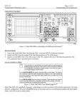
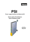
Test Equipment Solutions Datasheet
Test Equipment Solutions Ltd specialise in the second user sale, rental and distribution of
quality test & measurement (T&M) equipment. We stock all major equipment types such as
spectrum analyzers, signal generators, oscilloscopes, power meters, logic analysers etc from
all the major suppliers such as Agilent, Tektronix, Anritsu and Rohde & Schwarz.
We are focused at the professional end of the marketplace, primarily working with customers
for whom high performance, quality and service are key, whilst realising the cost savings that
second user equipment offers. As such, we fully test & refurbish equipment in our in-house,
traceable Lab. Items are supplied with manuals, accessories and typically a full no-quibble 2
year warranty. Our staff have extensive backgrounds in T&M, totalling over 150 years of
combined experience, which enables us to deliver industry-leading service and support. We
endeavour to be customer focused in every way right down to the detail, such as offering free
delivery on sales, covering the cost of warranty returns BOTH ways (plus supplying a loan
unit, if available) and supplying a free business tool with every order.
As well as the headline benefit of cost saving, second user offers shorter lead times, higher
reliability and multivendor solutions. Rental, of course, is ideal for shorter term needs and
offers fast delivery, flexibility, try-before-you-buy, zero capital expenditure, lower risk and off
balance sheet accounting. Both second user and rental improve the key business measure of
Return On Capital Employed.
We are based near Heathrow Airport in the UK from where we supply test equipment
worldwide. Our facility incorporates Sales, Support, Admin, Logistics and our own in-house
Lab.
All products supplied by Test Equipment Solutions include:
- No-quibble parts & labour warranty (we provide transport for UK mainland addresses).
- Free loan equipment during warranty repair, if available.
- Full electrical, mechanical and safety refurbishment in our in-house Lab.
- Certificate of Conformance (calibration available on request).
- Manuals and accessories required for normal operation.
- Free insured delivery to your UK mainland address (sales).
- Support from our team of seasoned Test & Measurement engineers.
- ISO9001 quality assurance.
Test equipment Solutions Ltd
Unit 8 Elder Way
Waterside Drive
Langley
Berkshire
SL3 6EP
T: +44 (0)1753 596000
F: +44 (0)1753 596001
Email: [email protected]
Web: www.TestEquipmentHQ.com
®
PM 3370B,
PM 3380B, PM 3384B,
PM 3390B and PM 3394B,
CombiScope® Instruments,
Autoranging DSO with a built-in
analog oscilloscope
This range of instruments comprises a total
of 5 models. All are digital storage
oscilloscopes with a real-time analog
oscilloscope built-in. They are equipped
with screen read-out, cursors and a fullly
triggered delayed timebase. They can be
switched to the familiar analog mode,
giving all the advantages of a real time
signal display, from the digital mode and
back, at the push of a button.
For optimum user convenience, this can be
done from the front panel or from the
probe-mounted command switch. The
digital mode offers unique AUTORANGING
capabilities for all channels as well as for
the timebase. Autoranging allows for
hands-free operation of the scope, with
continuously optimized settings matching
the signals applied.
All DSO benefits apply: trace storage, pretrigger view, calculated measurements,
hardcopy facilities, advanced trigger
modes, averaging and FFT. The probe
operated Touch-Hold-and-Measure™
freezes the display and instantly displays
measured signal parameters VDC, VRMS, Vpk-pk
and frequency.
Autoranging
Continuously adjusts the vertical
deflectionfactor and the timebase sweep
speed to keep an optimum display of the
input signals. Autoranging can be selected
individually for each of the input channels
and for the timebase (responding to trigger
signal).
Continuously variable timebase
Unique variable timebase works in both
the DSO mode (down to 1 µs/div.) as well
as in analog mode. When combined with
autoranging, the variable timebase will
keep a fixed number of cycles of the input
waveform on screen, even with changing
input signal frequency. This is ideal when
looking at frequency dependent
phenomena, or when used with rotating
machines and engines.
Autoset
Selects proper channel-, timebase- and
trigger settings for all channels, including
the PM 3370B’s, PM 3380B’s and
PM 3390B’s external trigger input.
Triggering is automatically on the lowest
frequency input signal. The function can
be customized by the user to support
personal preferences in the set-up.
Technical Data
Fast sampling
The sampling technique used in these
instruments, gives a sample rate of up to
25 GS/s in PM 339xB for repetitive signals
(10 GS/s in the other models). This results
in a time resolution of 40 ps for the
PM 339xB (100 ps for the other models).
The single shot sample rate of 200 MS/s is
also applied in the digital oversampling
peak-detect mode, to capture fast
transients and spikes as narrow as 5 ns at
correct amplitude. At any timebase setting !
Autocal
Automatic fine adjustment for enhanced
accuracy to get optimum performance even
under extreme environmental conditions.
Automatic testing
The additional pass / fail testing offered by
the Math+ option, as well as the
GPIB/IEEE-488.2 interface make these
scopes a powerful and fully programmable
tool in automatic test applications.
Memory
The 8K record length is optionally
expandable to 32K samples for one trace,
or up to 200 traces in memory at 512
samples per trace. And it’s even standard
on the PM 33x4B.
Technical Specifications
ANALOG MODE
VERTICAL DEFLECTION
Input channels
Full attenuator control on all four input
channels (PM 33x4B), or on both input
channels (PM 33x0B). External trigger
input signal can be displayed for ”trigger
view” (PM 33x0B). On screen channel
identifiers with ground level indicator.
CMRR
100:1 at 1 MHz, 25:1 at 50 MHz.
Channel isolation
PM 339xB:
50:1 at 200 MHz
PM 338xB:
50:1 at 100 MHz
PM 3370B:
50:1 at 60 MHz
HORIZONTAL
(Main and Delayed Timebase)
Display modes
PM 33x4B:
CH1, +/- CH2, CH3,
+/- CH4, Add, Subtract;
Alternate or chopped
automatically selected.
Display modes
Main Timebase (MTB),
Delayed Timebase (DTB),
Alternate Timebase (= MTB and DTB),
X-Y mode.
PM 33x0B:
Sweep speeds (magn. x1)
PM 339xB:
MTB: 0.5 s/div..... 20 ns/div.
in a 1-2-5-sequence.
Calibrated vernier gives
1.25 s/div..... 20 ns/div.
DTB: 0.5 ms/div... 20 ns/div.
in a 1-2-5 sequence.
PM 338xB and PM 3370B:
MTB : 0.5 s/div.... 50 ns/div.
in a 1-2-5-sequence.
Calibrated vernier gives
1.25 s/div ..... 50 ns/div.
DTB: 0.5 ms/div... 50 ns/div.
in a 1-2-5-sequence.
CH1, +/- CH2, Add,
Subtract; External Trigger
View; Alternate or
chopped automatically
selected.
Bandwidth (+5..... +40°C)
PM 339xB:
>200 MHz @ -3 dB,
PM 338xB:
>100 MHz @ -3 dB,
PM 3370B:
> 60 MHz @ -3 dB.
Bandwidth limiter
20 MHz @ -3 dB on all fully controllable
channels simultaneously.
Rise time
(calculated from the bandwidth)
PM 339xB:
< 1.75 ns,
PM 338xB:
< 3.5 ns,
PM 3370B:
< 5.8 ns.
Deflection Settings
Step attenuator:
2 mV/div..... 5V/div. in a
1-2-5 sequence
(full bandwidth).
Calibrated vernier:
2 mV/div.... 12.5 V/div.
Fastest sweep speed (magn. x10)
PM 339xB:
2 ns/div.
PM 338xB and
PM 3370B:
5 ns/div.
Error limit (magn. x1)
≤ [1.3% of reading + 0.5% of 8 divisions].
DELAY TIME MULTIPLIER
Resolution
1 : 40,000
External Trigger View (PM 33x0B):
100 mV/div. and
1 V/div.
Error limit (magn. x1)
≤ [0.8% of reading + 0.3% of 8 divisions +
4 ns].
Error limits
1.3% (measured over central 6 divisions).
Jitter
< 1 : 25,000
Input impedance
All models, all channels:
1 MΩ ± 1% // 25 pF
± 2 pF
PM 339xB:
user selectable 50Ω ± 1%.
Max. rated input voltage
In 1 MΩ position: ±150 VRMS CAT II
In 50Ω position: dc:±5 V, rms: 5 V,
ACpeak:±50 V.
Dynamic range
PM 339xB:
24 div. at 50 MHz
PM 338xB:
24 div. at 25 MHz
PM 3370B:
24 div. at 15 MHz
DTB trigger source
Starts after delay or triggered on any
channel or on External Trigger input
(PM 33x0B only).
Slope
Positive (+), Negative (-).
Coupling
DC, AC (<10 Hz), LF-rej. (30 kHz),
HF-rej. (30 kHz).
Trigger gap
0.4 div., user selectable 0.8 div. for
triggering on noisy signals.
Level range
± 8 div. or automatically within signal
peak-peak amplitude range.
Level indication
On screen level indicators and numerical
read-out.
Trigger sensitivity and bandwidth
(+5..... +40°C)
Sensitivity PM3370B PM338xB PM339xB
0.6 div.
30 MHz
50 MHz
100 MHz
1.2 div.
60 MHz
100 MHz
200 MHz
2.0 div.
150 MHz 200 MHz
300 MHz
TV Triggering
MTB trigger source
PM 33x4B: CH1.... CH4; Lines, Field 1,
Field 2, specific line using built-in line
counter. External trigger input optional,
replacing ”Line”
PM 33x0B: CH1, CH2, Ext.; Lines, Field 1,
Field 2, specific line using built-in line
counter.
Video standard
NTSC, PAL, SECAM, HDTV.
Delayed TB trigger source
Starts after delay or triggered on any input
channel or on External Trigger input
(PM 33x0B only); DTB triggers on edge or
on TV line. The Delayed TB can be used to
expand any part of the line selected with
the video line selector.
Signal polarity
Positive or negative video.
TRIGGERING
(Main and Delayed timebase)
Trigger modes
Auto free run, Triggered, Single;
Edge triggering, TV Triggering.
Sensitivity
0.7 div. (amplitude of sync. pulse).
X-Y MODE
EDGE TRIGGERING
X-deflection source
PM 33x4B:
CH1.... CH4, Line.
PM 33x0B:
CH1, CH2, External, Line.
MTB trigger source
PM 33x4B:
CH1.... CH4, Line. External
trigger input optional,
replacing ”Line”.
PM 33x0B:
CH1, CH2, External, Line.
X-deflection coefficient
Same as for vertical deflection, error limit
5% over central 6 div.
Dynamic range
20 div. up to 100 kHz,
> 10 div. up to 2 MHz.
®
ANALOG MODE (cont.)
Frequency response
≥ 2 MHz @ -3 dB.
Phase shift < 3° up to 100 kHz.
CURSOR MEASUREMENTS
Cursor modes and Read-out
Vertical:
dV, V1 to ground, V2 to
ground, ratio.
Horizontal:
dT, 1/dT (in Hz), ratio,
phase.
Horizontal and vertical cursors can be
used together.
Accuracy (magn. x1)
± 1% of full scale within the central 8
horizontal and 6 vertical divisions.
DIGITAL MODE
ACQUISITION
Repetitive Sample Rate
Random sampling gives an equivalent
sample rate up to 25 GS/s (PM 339xB) or
up to 10 GS/s (PM 3370B and PM 338xB)
on all input channels, over the full
bandwidth.
Single Shot Sample Rate
Real time sampling up to 200 MS/s (single
channel), 100 MS/s (dual channel).
In PM 33x4B, a fast chopper offers
200 ns horizontal resolution in 4 channel
single shot mode.
Bandwidth (+5..... +40°C)
PM 339xB:
200 MHz
(repetitive and single shot)
PM 338xB:
100 MHz
(repetitive and single shot)
PM 3370B:
60 MHz
(repetitive and single shot)
Calculated Maximum Captured
Frequency in single shot mode
• Using sine interpolation to reconstruct
signals at 5 samples per period:
40 MHz in 1 channel mode,
20 MHz in 2 channel mode,
1 MHz in 4 channel mode or when
trigger view (PM 33x0B) is active.
• For 10 samples per period with linear
interpolation:
20 MHz in 1 channel mode,
10 MHz in 2 channel mode,
0.5 MHz in 4 channel mode or when
trigger view (PM 33x0B) is active.
ADC Resolution
ADC resolution 8 bit, Memory resolution 16
bit. All mathematical operations and
averaging increase waveform resolution
beyond 8 bits.
Memory
Memory resolution 16 bit; Acquisition and
reference memory can be segmented
offering the choice between long
acquisition records or a maximum screen
update rate and a maximum number of
traces in memory. See table for full details
on acquisition length selections and total
Record length and trace storage
Acquisition
length
Trace storage
1 CH x 32K
3 traces
PM 3394B, PM 3384B
2 CH x 16K
4 CH x 8K
6 traces
12 traces
4 CH x 512s
208 traces
PM 3370B, PM 3380B and PM 3390B with Standard memory
Acquisition
1 CH x 8K
2 CH x 4K
2 CH + Tr.View x 2K
2 CH + Tr.View
length
x 512s
Trace storage
3 traces
6 traces
9 traces
30 traces
PM 3370B, PM 3380B and PM 3390B with Expanded Memory option
Acquisition
1 CH x 32K
2 CH x 16K
2 CH + Tr.View x 8K
2 CH + Tr.View
length
x 512s
Trace storage
3 traces
6 traces
9 traces
156 traces
number of traces that can be stored in
back-up memory. Figures include the MTB
acquisition memory as well as DTB
acquisition memory (available with 512
samples acquisition length only).
Window mode
2 or 4 windows to display two or four
traces above each other while using the
full dynamic range of the ADC (8 bit).
Averaging
Averaging reduces random noise contained
in the signal, while increasing the vertical
resolution. Averaging factor user selectable:
2, 4, 8, ..... 4096; Max. resolution: 14 bit.
HORIZONTAL
Peak detection
Captures glitches as narrow as 5 ns at any
timebase setting (single channel) or 10 ns
(dual channel and multiple channel,
alternating) and at correct amplitude.
Also very useful to capture high-frequency
components (like a modulated carrier) at
low timebase settings.
Envelope mode
For continuous tracking of changing
waveforms.
VERTICAL
Same as analog mode, unless specified
otherwise.
Auto-ranging vertical deflection
Automatically and continuously adapts
vertical deflection setting to have
2.... 6.4 division display of input signal.
Can be selected on any input channel
individually. Minimum deflection setting
automatically selected is 50 mV/div.
Vertical Magnification
Up to 32x magnification for higher
deflection sensitivity; can be combined
with averaging for increased resolution
(averaging factor selectable up to 4096x
resulting in a vertical resolution of 14 bit).
Display modes
PM 33x4B:
CH1, +/- CH2, CH3, +/CH4; Calculated Add and
Subtract.
PM 33x0B:
CH1, +/- CH2; Calculated
Add and Subtract. External
Trigger Input signal can be
displayed acting as a third
input channel.
Bandwidth limiter
20 MHz @ -3 dB.
Acquisition modes
Recurrent (Auto and Triggered), Single
Shot, Multiple single shot (as part of Math+
option), Roll, Triggered Roll. User selectable
AUTO-RANGING timebase in recurrent
modes.
X-Y mode
X-source: any trace in memory or any of
the input channels.
AUTO-RANGING timebase
Continuously adapts sweep speed to the
frequency of the trigger signal in order to
keep 2..... 6 cycles on screen; User
selectable function. Autoranging Timebase
can work with timebase in 1-2-5 range or
with continuously variable timebase,
stabilizing the number of cycles on screen.
Timebase modes
Main TB (MTB), Delayed TB (DTB),
Alternate TB (= MTB and DTB).
Delayed timebase starts after delay or
triggered on channel. Trigger coupling:
same as for analog mode.
Timebase (magn. x1)
Real time sampling:
200 s/div.... 500 ns/div.,
250 ns/div.
Recurrent:
200 ns/div..... 2 ns/div.
(5 ns/div. for PM 338xB
and PM 3370B)
Roll mode:
200 s/div..... 50 ms/div.
Variable timebase
Continuously variable sweep speed:
1 µs/div.... 500 ms/div. in
1 µs increments;
500 ms/div.... 200s/div.
better than 0.2%
increments.
Display resolution
Horizontal resolution (per trace) for x1
magnification: 500 samples = 10 divisions
= 1 screen width. Compression allows a
compact display of larger records.
DIGITAL MODE (cont.)
Magnification
x2, x4, ..... x32 (expansion) of any part of a
record;
x1/2, x1/4, ..... x1/64 (compression) of
records exceeding 512 samples.
Interpolation
• Dots only (shows acquired samples only).
• Linear interpolation.
• Sine interpolation (offers natural
representation of expanded single shot
acquisitions up to <10 ns/div.).
TRIGGERING
Edge triggering
Same as for analog mode, plus dual slope
triggering when used in single shot, real
time only mode.
TV triggering
Same as for analog mode.
Logic triggering modes
State (4 bit), Pattern (4 bit), Glitch
(time qualified pulse).
• State triggering (PM 33x4B only)
Any of the 4 channels can be selected
as the clock. Each of the other channels
can be monitored for being ”high”, ”low”
or ”don’t care”. The scope triggers if the
combination of the remaining channels
matches the user defined description
during a transition (+ or -, user
selectable) of the clock.
Max. clock rate: 150 MHz typical.
Sensitivity: 1.0 div. if time present
≥ 10 ns (≥ 20 ns for PM 3384B), 2 div. if
time present ≥ 2 ns (≥ 4 ns for
PM 3384B).
• Pattern triggering (PM 33x4B only)
The scope triggers if the combination of
the four channels matches the user
defined description. Each channel can be
monitored for being ”high”, ”low” or
”don’t care”.
Modes: Enter, Exit, Time qualified (lower
limit, upper limit, range).
Range of limits: 20 ns.... 167.7 ms;
Smallest resolution: 10 ns;
Sensitivity: 1.0 div. if time present ≥
10 ns, (≥ 20 ns for PM 3384B), 2 div. if
time present ≥ 2 ns, (≥ 4 ns for
PM 3384B).
• Glitch triggering (all models)
Minimum glitch width:
2 ns (4 ns PM 339xB), 4 ns (PM 338xB)
or 6 ns (PM 3370B).
Pulse width time qualification:
lower limit, upper limit, range.
Limits must be in the range
20 ns... 167.7 ms; Smallest resolution
10 ns.
DELAY
Time delay
0.... 1000 div., continuously adjustable.
Pre-trigger view
Up to 1 full record (= 160 div. for an 8K
record, or 640 div. for a 32K memory)
Event delay
1.... 16384 events;
Max. count rate 50 MHz (typical);
Source: any channel (including External
Trigger on PM 33x0B); Modes: Event delay,
Time delay after event delay.
Interface installed as a standard. Enables
printing and plotting as well as full remote
control of the instruments. Also allows for
serial communication trace dump to
arbitrary waveform generator.
DB-9 male connector.
Delay modes
Start after time delay, Wait for trigger after
time delay.
Handshake
DSR/DTR, CTS/RTS, or Xon/Xoff.
Baudrate
75.... 19k2 full duplex, 38k4 dump only.
CURSOR MEASUREMENTS
Cursor modes
Horizontal, Vertical, Both; Free or coupled
to trace. Cursors can be used throughout
the memory.
Read-out
Vertical:
dV, V1 to ground, V2 to
ground, dVratio
Horizontal:
dT, 1/dT (in Hz), T1&T2 to
trigger moment, dTratio,
phase.
For phase measurements, the cycle is
automatically referenced to trigger signal.
CALCULATED
MEASUREMENTS
General
Measurements can be performed over a
complete record or within a cursor limited
area. Statistics mode provides minimum,
mean and maximum measurement result
per measurement.
Format
1 stopbit; 7 or 8 databits; odd/even/no
parity.
Protocol
CPL = Compact Programming Language;
A reduced set of powerful instruction for
full remote control through RS-232C.
Waveform dump
Trace dump to PM 5150, PM 5138A and
PM 5139 arbitrary waveform generator
(requires generator to be equipped with
RS-232C interface).
GPIB/IEEE-488.2 INTERFACE
Factory installed option (next to RS-232C).
Remote control conform SCPI (Standard
Commands for Programmable Instruments)
= standardized protocol. Fully compatible
with IEEE-488.2.
Waveform dump
Trace dump to PM 5150, PM 5138A and
PM5139 arbitrary waveform generator
(requires generator to be equipped with
IEEE interface).
Volt
DC, RMS, Minimum, Maximum, Peak to
Peak, Low level, High level, Overshoot (pos.
or neg.), Preshoot (pos. or neg.).
HARDCOPY
Time
Frequency, Period, Pulsewidth, Rise time,
Fall time, Duty cycle.
Using RS-232C (standard) or GPIB/IEEE488.2 (optional) interface. Centronics
output optionally available through PAC33
Print Adapter Cable, giving RS-232 to
Centronics conversion.
Delay
Between channels; Rising and falling
edges independently selectable.
Quick Measurement
Probe mounted ”Command Switch”
operates ‘Touch, Hold and Measure’, giving
calculated measurements of frequency, VDC,
VRMS and Vpkpk.
Output
Printed or plotted hardcopy of the screen
(digital mode) in sizable format. If selected,
with status report of the complete
instrument setting and date- and
timestamp of the trigger moment and the
moment the hardcopy action was started.
Two lines of on-screen text (32 characters
per line) can be added for user
documentation.
PROCESSING
Standard
Add, Subtract, Multiply, Digital filter (for
noise reduction and increased resolution
by means of digital low pass filtering after
single shot capture).
In Math+ option
Integrate, Differentiate, FFT, Histogram.
GENERAL
INTERFACING
RS-232C SERIAL INTERFACE
Printers
9 pin matrix printers (FX-80 compatible),
24 pin matrix printers (LQ-1500
compatible), ThinkJet (HP2225) and
compatibles, HP LaserJet (series II & III)
and compatibles incl. HP DeskJet, HP540
DeskJet compatibles.
Plotters
HP7440, HP7470A, HP7475A, HP7550,
standard HPGL, PM8277, PM8278 and
compatibles. HPGL file format is recognized
by most drawing- and wordprocessor
packages for direct inclusion of screen
plots in documents, reports etc.
®
Camera
Camera kit including bezel adapter
available as optional accessory.
Altitude
Max. 4.6 km = 15,000 ft (operating),
12 km = 40,000 ft (transport).
MISCELLANEOUS
Vibration
Frequency 5.... 55 Hz;
Max. acceleration at 55 Hz: 30 m/s2.
Setting Memory
10 complete instrument set-ups, with
battery back-up.
Probe adjustment output
600 mV peak-peak (± 1%), 2 kHz (± 20%)
squarewave.
Z-modulation input
BNC, 10 kΩ, < 0.5V unblanked, >2.4 V
blanked (in analog mode only).
Time between calibrations
2000 hours or 1 year with error limits
specified. 4000 hours or 2 years at double
the error limits.
Probe
Automatic detection of probe attenuation
factor using indication ring. Manually
selectable scale factors are part of Math+
option. Probe mounted Command Switch for
control of user selectable function: initiate
Autoset, initiate Quick Measure function,
switch from analog mode to Digital Storage
mode or back, select setting from memory.
POWER SUPPLY
Line voltage
100.... 240V (± 10%) in one range.
Line frequency
50.... 400 Hz (± 10%).
Power consumption
115 W (130 W with all options installed).
Shock
6 shocks along each axis, half sine wave,
6.... 9 ms, peak acceleration 400 m/s2.
Bench handling
Meets MIL-STD-810, method 516,
procedure V
EMI
VDE 0871 Grenzwertklasse B;
MIL-Std-461C: CE01 Part 2 (narrow band),
CE03 Part 4, CS01 Part 2, CS06 Part 5
(300 V max.), RE01 Part 5 and 6, RE02
Part 2 (1 GHz max.).
Magnetic susceptibility
Deflection for extreme conditions:
<0.7 div/mT, tested at 1.42 mT peak-peak,
45.... 66 Hz, in any direction.
SAFETY
Meets requirements of
EN 61010-1 CAT II Pollution Degree 2,
UL1244, CSA C22.2 No231, Low Voltage
Directive 73/23/EEC.
ELECTROMAGNETIC
COMPATIBILITY (EMC)
Meets requirements of
EMC directive 89/336/EEC:
emisson EN50081.1, susceptibility
EN50082.1
MECHANICAL DATA
Meets requirements of
MIL-STD-461C:
Part2 CE01 (narrow band), Part4 CE03
Part2 CS01, Part5 CS06 (limited to 300V)
Part5 and 6 RE01, Part2 RE02 (max. 1 GHz)
Fan
Proportionally regulated forced air.
STANDARD ACCESSORIES
Width x Height x Length
excluding handle and feet:
341 x 139 x 481 mm
(13.4 x 5.5 x 18.9 inch),
including handle and feet:
391 x 147 x 551 mm
(15.4 x 5.8 x 21.7 inch).
Weight
9.5 kg = 21 lb.
ENVIRONMENTAL DATA
Meets requirements of
MIL-T-28800D Type III, Class 3, Style D,
Color R, as specified:
Temperature range
0°C..... +50°C (operating),
-40°C..... +70°C (storage).
Humidity
95% (storage).
Included
• Two 10:1 probes with read-out and
command switch, supporting full
bandwidth and command switch
(PM 9010/091 or PM 9020/091, or
equivalent);
• Operating guide;
• Reference manual;
• Front cover;
• Power cord;
• Guide to mathematic functions and
SCPI/IEEE manual when applicable;
• Two LR-6 (AA-size) batteries;
• Free service manual upon request.
OPTIONS
GPIB / IEEE-488.2 OPTION
Gives full remote control, as well as
waveform data transfer. See ”Interfacing”
for further details.
EXPANDED MEMORY
Allows acquisition and storage of traces up
to 32K samples or storage of up to 200
traces of 512 samples each. See table
”Record length and trace storage” for
details. The memory extension is part of
the PM 33x4B as a standard, and is
optional on the PM 33x0B.
MATH+ OPTION
Additional processing
Integrate, Differentiate, FFT, Histogram.
FFT is equipped with Hamming, Hanning
and rectangular window. Relative level
(dB) or absolute signal level read-out
(mVRMS, dBm in 50Ω, dBm in 600Ω, dBmV).
Pass / Fail testing
Tests waveforms against reference
envelope (created internally using cursor
controls, or externally in a PC);
• Tests calculated measurements against
preset limits;
• Tests cursor measurement against preset
limits.
Gives audible warning, hardware output
signal, Locks, Saves waveform, Prints, or
Plots if test fails. If connected to PC with
FlukeView® CombiScope software running,
consecutive failing waveform plots can be
stored automatically in the PC for long term
process monitoring.
•
Multiple single shot
Captures and stores in internal memory
consecutive single shot acquisitions, with
time and date stamps.
Max. number of single shots stored:
PM 33x4B:
200 traces
PM 33x0B with standard memory:
8 sets of up to 3 traces
PM 33x0B with expanded memory:
50 sets of up to 3 traces
Advanced cursors
Amplitude qualified cursors for timing
measurements with time cursors
automatically positioned at a signal level
relative to the signals Max.peak, Min. peak,
High level, Low level, or on absolute levels.
AUX OUTPUTS AND
EXTERNAL TRIGGER INPUT
•
•
•
•
Channel 1 output (20 mV/div. into
1 MΩ, 10 mV/div. into 50Ω)
MTB Gate output (0 / 5V nominal,
>3.7 ±1.3 V while MTB running); output
impedance 1 kΩ.
DTB Gate output (0 / 5V nominal,
>3.7 ±1.3 V while DTB running); output
impedance 1 kΩ.
External Trigger input (BNC input on
rear of the instrument). Input impedance
1 MΩ ±1% // 25 pF ± 5 pF. Trigger
input sensitivity 200 mV at 10 MHz;
Max. input voltage ± 400 V.
(External Trigger input is part of the
option with PM 33x4B only).
®
ORDERING INFORMATION
A choice of 5 models in Fluke Autoranging CombiScope series
PM 3370B
PM 3380B
PM 3384B
Model numbers
PM 3370B
60 MHz two channel
Autoranging CombiScope
PM 3380B
100 MHz two channel
Autoranging CombiScope
PM 3384B
100 MHz full four channel
Autoranging CombiScope
PM 3390B
200 MHz two channel
Autoranging CombiScope
PM 3394B
200 MHz full four channel
Autoranging CombiScope
Bandwidth
Sample Rate
for repetitive signals
for single shot appl.
Channels
Max. acquisition record
(+ optional)
Analog scope built-in
Autoranging
RS-232 interface
PM 3390B
PM 3394B
60 MHz
100 MHz
100 MHz
200 MHz
200 MHz
10 GS/s
200 MS/s
2 + Ext.Trig.
8K
(32K)
Yes
Yes
standard
10 GS/s
200 MS/s
2 + Ext.Trig.
8K
(32K)
Yes
Yes
standard
10 GS/s
200 MS/s
4
32K
25 GS/s
200 MS/s
2 + Ext.Trig.
8K
(32K)
Yes
Yes
standard
25 GS/s
200 MS/s
4
32K
Yes
Yes
standard
Yes
Yes
standard
Optional configurations
When ordering, select one of the following
configuration options and add
to the basic typenumber:
for PM 3370B,
/02n
/08n
/42n
/48n
/93n
/99n
PM 3380B and PM 3390B:
Math+
Math+ + EM
IEEE-488 + Math+
IEEE + Math+ + EM
IEEE + Aux.Out. + Math+
IEEE + Aux.Out. + Math+
+ EM
for PM 3384B
/08n
/48n
/99n
and PM 3394B:
Math+ + EM
IEEE + Math+ + EM
IEEE + Aux.Out./Ext.Trig.
+ Math+ + EM
The ’n’ specifies the power cord option. To
order with your power cord, replace the ’n’
according to the following table:
1
Universal Euro 230V/16A
3
Standard North American
120V/15A
4
UK 240V/13A
5
Switzerland 230V/16A
8
Australia 240V/10A
Fluke Corporation
P.O. Box 9090, Everett, WA 98206
Fluke Europe B.V.
P.O. Box 1186,
5602 BD Eindhoven,
The Netherlands
For more information call:
In the U.S.A.: (800) 443-5853
or Fax: (425) 356-5116
In Europe/M-East:
+31 (0)40 2 678 200
or Fax: +31 (0)40 2 678 222
In Canada: (905) 890-7600
or Fax: (905) 890-6866
From other countries:
+1(425) 356-5500
or Fax: +1 (425) 356-5116
Web access: http://www.fluke.com
©Copyright 1998 Fluke Corporation.
All rights reserved.