1
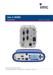
imc C-SERIE
Instruction book
Version 2.0 Rev 2 - 03.01.2014
© 2014 imc Meßsysteme GmbH
imc Meßsysteme GmbH • Voltastraße 5 • 13355 Berlin • Germany
2
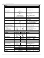
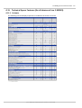
Table of contents
Table of contents
imc C-SERIES
9
1.1 Guide...................................................................................................................................
to Using the Manual
................................................................................................................................... 10
1.2 Guidelines
.........................................................................................................................................................
10
1.2.1 Certificates
and Quality Management
.........................................................................................................................................................
10
1.2.2 imc Guarantee
.........................................................................................................................................................
10
1.2.3 ElektroG, RoHS, WEEE
.........................................................................................................................................................
11
1.2.4 Product improvement
.........................................................................................................................................................
12
1.2.5 Important notes
..................................................................................................................................................
12
1.2.5.1 Remarks Concerning EMC
.................................................................................................................................................. 12
1.2.5.2 FCC-Note
.................................................................................................................................................. 13
1.2.5.3 Cables
..................................................................................................................................................
13
1.2.5.4 Other
Provisions
...................................................................................................................................
13
1.3 General
Notes
.........................................................................................................................................................
13
1.3.1 Instruction
manual
.........................................................................................................................................................
14
1.3.2 Liability limitations
.........................................................................................................................................................
14
1.3.3 Guarantee
.........................................................................................................................................................
14
1.3.4 Before starting
.........................................................................................................................................................
14
1.3.5 Notes on maintenance and servicing
.........................................................................................................................................................
15
1.3.6 Safety
..................................................................................................................................................
15
1.3.6.1 Responsibility of the user
..................................................................................................................................................
15
1.3.6.2 Operating
personnel
..................................................................................................................................................
16
1.3.6.3 Special dangers
...................................................................................................................................
17
1.4 Transport
and storage
.........................................................................................................................................................
17
1.4.1 After
unpacking ...
.........................................................................................................................................................
17
1.4.2 Transporting
the device
......................................................................................................................................................... 17
1.4.3 Storage
......................................................................................................................................................... 18
1.4.4 Cleaning
...................................................................................................................................
18
1.5 Precautions for operation
.........................................................................................................................................................
18
1.5.1 Grounding,
shielding
..................................................................................................................................................
19
1.5.1.1 Devices
with non-isolated power supply
..................................................................................................................................................
19
1.5.1.2 Devices
with isolated power supply
19
1.5.1.2.1...........................................................................................................................................
Grounding with the use of the included power adapter
19
1.5.1.2.2...........................................................................................................................................
Grounding with power supplied by a car battery
.................................................................................................................................................. 20
1.5.1.3 Shielding
..................................................................................................................................................
20
1.5.1.4 Potential
difference with synchronized devices
.........................................................................................................................................................
21
1.5.2 Power
supply
..................................................................................................................................................
22
1.5.2.1 Main
switch
..................................................................................................................................................
23
1.5.2.2 Remote
control of the main switch
1.5.3 UPS......................................................................................................................................................... 24
..................................................................................................................................................
24
1.5.3.1 Buffering
time constant and maximum buffer duration
..................................................................................................................................................
24
1.5.3.2 Charging
power
..................................................................................................................................................
24
1.5.3.3 Take-over
threshold
.........................................................................................................................................................
25
1.5.4 Rechargeable
accumulators and batteries
..................................................................................................................................................
25
1.5.4.1 Lead-gel
batteries
.........................................................................................................................................................
25
1.5.5 Fuses
(polarity-inversion protection)
Properties of the imc C-SERIES
© 2014 imc Meßsysteme GmbH
Table of contents
...................................................................................................................................
27
2.1 Device
Overview
...................................................................................................................................
28
2.2 Operating
software imc DEVICES and imc STUDIO
...................................................................................................................................
29
2.3 Sampling
interval
2.4 TEDS................................................................................................................................... 29
...................................................................................................................................
30
2.5 Specific
parameters
...................................................................................................................................
30
2.6 Measurement
types
.........................................................................................................................................................
30
2.6.1 Temperature
measurement
..................................................................................................................................................
31
2.6.1.1 Thermocouples
as per DIN and IEC
..................................................................................................................................................
31
2.6.1.2 Pt100
(RTD) - measurement
..................................................................................................................................................
31
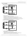
2.6.1.3 imc
Thermo connector
2.6.1.3.1 Schematic: imc Thermo connector (ACC/DSUB-T4) with isolated
........................................................................................................................................... 32
voltage channels
.........................................................................................................................................................
34
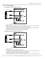
2.6.2 Bridge
measurements
..................................................................................................................................................
34
2.6.2.1 General
remarks
..................................................................................................................................................
34
2.6.2.2 Bridge
measurements with wire strain gauges (WSGs)
35
2.6.2.2.1...........................................................................................................................................
Quarter bridge for 120 Ohm WSG
35
2.6.2.2.2...........................................................................................................................................
General half bridge
36
2.6.2.2.3...........................................................................................................................................
Poisson half bridge
36
2.6.2.2.4...........................................................................................................................................
Half bridge with two active strain gauges in uniaxial direction
37
2.6.2.2.5...........................................................................................................................................
Half bridges with one active and one passive strain gauge
37
2.6.2.2.6...........................................................................................................................................
General Full bridge
38
2.6.2.2.7...........................................................................................................................................
Full bridge with Poisson strain gauges in opposed branches
38
2.6.2.2.8...........................................................................................................................................
Full bridge with Poisson strain gauges in adjacent branches
39
2.6.2.2.9...........................................................................................................................................
Full bridge with 4 active strain gauges in uniaxial direction
...........................................................................................................................................
39
2.6.2.2.10
Full bridge (Half bridge-shear strain) with two active strain gauges
...........................................................................................................................................
40
2.6.2.2.11
Scaling for the strain analysis
.........................................................................................................................................................
41
2.6.3 Incremental
encoders
..................................................................................................................................................
41
2.6.3.1 Signals
and conditioning
41
2.6.3.1.1...........................................................................................................................................
Mode
41
2.6.3.1.2...........................................................................................................................................
Event-counting
42
2.6.3.1.3...........................................................................................................................................
Time measurements
43
2.6.3.1.4...........................................................................................................................................
Combination mode
44
2.6.3.1.5...........................................................................................................................................
Differential measurement procedures
44
2.6.3.1.6...........................................................................................................................................
Cumulative measurements
44
2.6.3.1.7...........................................................................................................................................
Scaling
46
2.6.3.1.8...........................................................................................................................................
Comparator conditioning
47
2.6.3.1.9...........................................................................................................................................
Single-signal/ Two-signal
...........................................................................................................................................
47
2.6.3.1.10
Zero pulse (index)
..................................................................................................................................................
48
2.6.3.2 Mode
(events-counting)
48
2.6.3.2.1...........................................................................................................................................
Events
48
2.6.3.2.2...........................................................................................................................................
Distance
49
2.6.3.2.3...........................................................................................................................................
Angle
..................................................................................................................................................
50
2.6.3.3 Mode
(Time measurement)
50
2.6.3.3.1...........................................................................................................................................
Time measurement
51
2.6.3.3.2...........................................................................................................................................
Pulse Time
51
2.6.3.3.3...........................................................................................................................................
PWM
..................................................................................................................................................
52
2.6.3.4 Mode
(combined measurement)
52
2.6.3.4.1...........................................................................................................................................
Frequency
52
2.6.3.4.2...........................................................................................................................................
Speed
52
2.6.3.4.3...........................................................................................................................................
RPM
.........................................................................................................................................................
53
2.6.4 Measurement
with current-fed sensors
..................................................................................................................................................
53
2.6.4.1 Supply
current
© 2014 imc Meßsysteme GmbH
3
4
Table of contents
.........................................................................................................................................................
54
2.6.5 Overdriving
a measurement range
Device description
...................................................................................................................................
55
3.1 Hardware
configuration of all devices
.........................................................................................................................................................
55
3.1.1 Digital
In- and Outputs, Inputs for Incremental encoders
..................................................................................................................................................
55
3.1.1.1 Digital Inputs
56
3.1.1.1.1...........................................................................................................................................
Input voltage
...........................................................................................................................................
56
3.1.1.1.2 Sampling interval and brief signal levels
..................................................................................................................................................
57
3.1.1.2 Digital outputs
...........................................................................................................................................
58
3.1.1.2.1 Block schematic
...........................................................................................................................................
58
3.1.1.2.2 Possible configurations
..................................................................................................................................................
59
3.1.1.3 Incremental encoder channels
...........................................................................................................................................
59
3.1.1.3.1 Sensor types, synchronization
...........................................................................................................................................
60
3.1.1.3.2 Comparator conditioning
...........................................................................................................................................
61
3.1.1.3.3 Structure
...........................................................................................................................................
61
3.1.1.3.4 Channel assignment
...........................................................................................................................................
62
3.1.1.3.5 Incremental encoder track configuration options
...........................................................................................................................................
62
3.1.1.3.6 Block schematic
...........................................................................................................................................
63
3.1.1.3.7 Connection
......................................................................................................................................
63
3.1.1.3.7.1 Connection: Open-Collector Sensor
......................................................................................................................................
63
3.1.1.3.7.2 Connection: Sensors with RS422 differential line drivers
......................................................................................................................................
64
3.1.1.3.7.3 Connection: Sensors with current signals
.........................................................................................................................................................
65
3.1.2 Analog outputs
.........................................................................................................................................................
65
3.1.3 Field bus cabling
..................................................................................................................................................
65
3.1.3.1 CAN-cabling
65
3.1.3.1.1...........................................................................................................................................
Connecting the terminators
................................................................................................................................... 66
3.2 Miscellaneous
.........................................................................................................................................................
66
3.2.1 Filter
settings
..................................................................................................................................................
66
3.2.1.1 Theoretical background
..................................................................................................................................................
66
3.2.1.2 General
filter concept
..................................................................................................................................................
66
3.2.1.3 Implemented filters
.........................................................................................................................................................
68
3.2.2 ICP-Expansion connector for voltage channels
..................................................................................................................................................
68
3.2.2.1 IEPE (ICP)-Sensors
..................................................................................................................................................
68
3.2.2.2 ICP-Expansion
connector
..................................................................................................................................................
69
3.2.2.3 Configuration ICP-connector
..................................................................................................................................................
70
3.2.2.4 Circuit schematic: ICP-connector
..................................................................................................................................................
71
3.2.2.5 ACC/DSUB-ICP2-BNC
..................................................................................................................................................
72
3.2.2.6 ACC/DSUB-ICP2I(M)-BNC
.........................................................................................................................................................
73
3.2.3 External sensor supply
..................................................................................................................................................
73
3.2.3.1 External +5 V supply voltage
..................................................................................................................................................
73
3.2.3.2 Sensor
supply optional (2.5 V to 24 V)
.........................................................................................................................................................
74
3.2.4 DSUB-Q2 charging amplifier
.........................................................................................................................................................
75
3.2.5 LEDs and BEEPER
.........................................................................................................................................................
75
3.2.6 Modem connection
.........................................................................................................................................................
75
3.2.7 SYNC
..................................................................................................................................................
75
3.2.7.1 Optical SYNC Adapter: ACC/SYNC-FIBRE
.........................................................................................................................................................
77
3.2.8 IRIG-B
module
.........................................................................................................................................................
78
3.2.9 GPS
.........................................................................................................................................................
79
3.2.10 Operation without PC
..................................................................................................................................................
80
3.2.10.1 Graphical display
...................................................................................................................................
81
3.3 CS-1016
[-N], CL-1032 [-N]
.........................................................................................................................................................
81
3.3.1 Voltage
measurement
.........................................................................................................................................................
81
3.3.2 Current measurement
© 2014 imc Meßsysteme GmbH
Table of contents
.........................................................................................................................................................
81
3.3.3 Current
fed sensors
.........................................................................................................................................................
81
3.3.4 Bandwidth
.........................................................................................................................................................
81
3.3.5 Connection
...................................................................................................................................
82
3.4 CS-1208-1
[-N], CL-1224-1 [-N]
.........................................................................................................................................................
82
3.4.1 Voltage
measurement
..................................................................................................................................................
82
3.4.1.1 Voltage source with ground reference
..................................................................................................................................................
83
3.4.1.2 Voltage
source without ground reference
..................................................................................................................................................
83
3.4.1.3 Voltage source at other, fixed potential
..................................................................................................................................................
83
3.4.1.4 Voltage measurement: With taring
.........................................................................................................................................................
84
3.4.2 Current measurement
.........................................................................................................................................................
84
3.4.3 Current fed sensors
.........................................................................................................................................................
84
3.4.4 Bandwidth
.........................................................................................................................................................
84
3.4.5 Connection
................................................................................................................................... 85
3.5 CL-2108
.........................................................................................................................................................
85
3.5.1 High-voltage
channels
..................................................................................................................................................
85
3.5.1.1 Voltage measurement
.........................................................................................................................................................
86
3.5.2 Current
measurement channels
..................................................................................................................................................
86
3.5.2.1 Current measurement using Current Probes
..................................................................................................................................................
87
3.5.2.2 Current
measurement using Rogowski Coil
..................................................................................................................................................
89
3.5.2.3 Notes on making settings in the imc operating software
..................................................................................................................................................
90
3.5.2.4 Voltage measurement
.........................................................................................................................................................
91
3.5.3 Pin configuration and cable wiring
..................................................................................................................................................
91
3.5.3.1 Notes on the measurement setup
......................................................................................................................................................... 92
3.5.4 Connection
.................................................................................................................................................. 92
3.5.4.1 Voltages
.................................................................................................................................................. 93
3.5.4.2 Currents
.................................................................................................................................................. 93
3.5.4.3 General
.........................................................................................................................................................
94
3.5.5 Bandwidth
...................................................................................................................................
95
3.6 CS-3008-1
[-N], CL-3016-1 [-N], CL-3024-1 [-N]
.........................................................................................................................................................
95
3.6.1 Voltage
measurement
..................................................................................................................................................
95
3.6.1.1 Input coupling
..................................................................................................................................................
96
3.6.1.2 Case
1: Voltage source with ground reference
..................................................................................................................................................
96
3.6.1.3 Case 2: Voltage source without ground reference
.........................................................................................................................................................
97
3.6.2 Bandwidth
.........................................................................................................................................................
97
3.6.3 Connection
...................................................................................................................................
98
3.7 CS-4108
[-N], CL-4124 [-N]
.........................................................................................................................................................
98
3.7.1 Voltage
measurement
.........................................................................................................................................................
99
3.7.2 Temperature
measurement
..................................................................................................................................................
99
3.7.2.1 Thermocouple
measurement
..................................................................................................................................................
99
3.7.2.2 Pt100
(RTD) - Measurement
.........................................................................................................................................................
99
3.7.3 Current
fed sensors
.........................................................................................................................................................
100
3.7.4 Current
measurement
101
3.7.4.1 ..................................................................................................................................................
Current measurement with internal shunt
......................................................................................................................................................... 101
3.7.5 Bandwidth
......................................................................................................................................................... 101
3.7.6 Connection
...................................................................................................................................
102
3.8 CS-5008-1 [-N], CL-5016-1 [-N], CX-5032-1 [-N]
.........................................................................................................................................................
102
3.8.1 Bridge
measurement
103
3.8.1.1 ..................................................................................................................................................
Full bridge
103
3.8.1.2 ..................................................................................................................................................
Half bridge
104
3.8.1.3 ..................................................................................................................................................
Quarter bridge
104
3.8.1.4 ..................................................................................................................................................
Sense and initial unbalance
105
3.8.1.5 ..................................................................................................................................................
Balancing and shunt calibration
© 2014 imc Meßsysteme GmbH
5
6
Table of contents
.........................................................................................................................................................
106
3.8.2 Voltage
measurement
..................................................................................................................................................
106
3.8.2.1 Voltage source with ground reference
106
3.8.2.2 ..................................................................................................................................................
Voltage source without ground reference
..................................................................................................................................................
107
3.8.2.3 Voltage source at a different fixed potential
.........................................................................................................................................................
107
3.8.3 Current measurement
..................................................................................................................................................
107
3.8.3.1 Differential current measurement
108
3.8.3.2 ..................................................................................................................................................
Ground-referenced current measurement
..................................................................................................................................................
108
3.8.3.3 2-wire for sensors with a current signal and variable supply
.........................................................................................................................................................
109
3.8.4 Sensors with current feed
.........................................................................................................................................................
109
3.8.5 Sensor supply
.........................................................................................................................................................
109
3.8.6 Bandwidth
.........................................................................................................................................................
109
3.8.7 Connection
...................................................................................................................................
110
3.9 CS-6004-1
[-N], CL-6012-1 [-N]
.........................................................................................................................................................
111
3.9.1 Bridge
measurement
..................................................................................................................................................
112
3.9.1.1 Full bridge
113
3.9.1.2 ..................................................................................................................................................
Half bridge
..................................................................................................................................................
115
3.9.1.3 Quarter bridge
..................................................................................................................................................
116
3.9.1.4 Background info on quarter-bridge configuration
.........................................................................................................................................................
117
3.9.2 Carrier frequency amplifier: Modulation principle
.........................................................................................................................................................
118
3.9.3 Bandwidth
.........................................................................................................................................................
118
3.9.4 Connection
...................................................................................................................................
119
3.10 CS-7008-1
[-N], CL-7016-1 [-N] and CS-7008, CL-7016
.........................................................................................................................................................
119
3.10.1 Voltage
measurement
..................................................................................................................................................
120
3.10.1.1 Voltage source with ground reference
120
3.10.1.2..................................................................................................................................................
Voltage source without ground reference
..................................................................................................................................................
121
3.10.1.3 Voltage source at a different fixed potential
.........................................................................................................................................................
121
3.10.2 Bridge measurement
..................................................................................................................................................
122
3.10.2.1 Full bridge
122
3.10.2.2..................................................................................................................................................
Half bridge
..................................................................................................................................................
123
3.10.2.3 Quarter bridge
..................................................................................................................................................
124
3.10.2.4 Sense and initial unbalance
..................................................................................................................................................
124
3.10.2.5 Balancing and shunt calibration
.........................................................................................................................................................
125
3.10.3 Current measurement
..................................................................................................................................................
125
3.10.3.1 Differential current measurement
125
3.10.3.2..................................................................................................................................................
Ground-referenced current measurement
..................................................................................................................................................
126
3.10.3.3 2-wire for sensors with a current signal and variable supply
.........................................................................................................................................................
127
3.10.4 Temperature measurement
..................................................................................................................................................
127
3.10.4.1 Thermocouple measurement
...........................................................................................................................................
127
3.10.4.1.1
Thermocouple mounted with ground reference
...........................................................................................................................................
128
3.10.4.1.2 Thermocouple mounted without ground reference
..................................................................................................................................................
129
3.10.4.2 Pt100/ RTD measurement
...........................................................................................................................................
129
3.10.4.2.1 Pt100 in 4-wire configuration
...........................................................................................................................................
130
3.10.4.2.2 Pt100 in 2-wire configuration
...........................................................................................................................................
130
3.10.4.2.3 Pt100 in 3-wire configuration
..................................................................................................................................................
130
3.10.4.3 Probe-breakage recognition
.........................................................................................................................................................
132
3.10.5 Current fed sensors
.........................................................................................................................................................
132
3.10.6 Charging amplifier
.........................................................................................................................................................
132
3.10.7 Userdefined characteristic curves
.........................................................................................................................................................
132
3.10.8 Sensor supply module
.........................................................................................................................................................
132
3.10.9 Bandwidth
.........................................................................................................................................................
133
3.10.10 Connection
................................................................................................................................... 134
3.11 CS-8008
.........................................................................................................................................................
134
3.11.1 Voltage
measurement
© 2014 imc Meßsysteme GmbH
Table of contents
.........................................................................................................................................................
134
3.11.2 1/3-octave
calculation
.........................................................................................................................................................
135
3.11.3 Current fed sensors
.........................................................................................................................................................
135
3.11.4 Bandwidth
.........................................................................................................................................................
135
3.11.5 Connection
Technical specifications
...................................................................................................................................
136
4.1 General
technical specs for all devices of imc C-SERIES
...................................................................................................................................
139
4.2 Cx-10xx
analog inputs
...................................................................................................................................
141
4.3 Cx-12xx
analog inputs
...................................................................................................................................
143
4.4 CL-2108
general technical data
.........................................................................................................................................................
143
4.4.1 Cx-21xx
analog inputs
...................................................................................................................................
147
4.5 Cx-30xx analog inputs
...................................................................................................................................
149
4.6 Cx-41xx
analog inputs
...................................................................................................................................
153
4.7 Cx-50xx
analog inputs
...................................................................................................................................
157
4.8 Cx-60xx
analog inputs
...................................................................................................................................
161
4.9 Cx-70xx
analog inputs
...................................................................................................................................
166
4.10 CS-8008
general technical data
.........................................................................................................................................................
166
4.10.1 C-80xx
analog inputs
...................................................................................................................................
169
4.11 Technical
Specs: Features (for all devices of imc C-SERIES)
......................................................................................................................................................... 169
4.11.1 Variants
.........................................................................................................................................................
170
4.11.2 Digital
Inputs
.........................................................................................................................................................
171
4.11.3 Digital outputs
.........................................................................................................................................................
172
4.11.4 Incremental encoder channels
.........................................................................................................................................................
173
4.11.5 Analog outputs
.........................................................................................................................................................
174
4.11.6 CAN-Bus Interface
.........................................................................................................................................................
174
4.11.7 Synchronization and time base
................................................................................................................................... 176
4.12 Miscellaneous
.........................................................................................................................................................
176
4.12.1 imc
Graphics Display
.........................................................................................................................................................
177
4.12.2 ACC/DSUB-ICP
ICP-expansion plug
......................................................................................................................................................... 178
4.12.3 ACC/DSUB-ICP2-BNC
.........................................................................................................................................................
179
4.12.4 Technical
Specs - ACC/DSUB(M)-ICP2I-BNC
......................................................................................................................................................... 180
4.12.5 ACC/DSUB-Q2
.........................................................................................................................................................
181
4.12.6 ACC/DSUB-ENC4-IU
connector for incremental sensors with current signals
......................................................................................................................................................... 182
4.12.7 ACC/SYNC-FIBRE
......................................................................................................................................................... 183
4.12.8 IRIG-B
.........................................................................................................................................................
184
4.12.9 SUPPLY
Sensor supply module
185
4.12.10 .........................................................................................................................................................
WiFi (WLAN) Connection
Connectors
...................................................................................................................................
186
5.1 Connecting
DSUB-15 adapter plug
.........................................................................................................................................................
187
5.1.1 Overview
of the modules and connectors
...................................................................................................................................
188
5.2 Metal connector
...................................................................................................................................
189
5.3 DSUB-15
Pin configuration
.........................................................................................................................................................
189
5.3.1 Standard
and Universal connector
.........................................................................................................................................................
190
5.3.2 Special
connector
.........................................................................................................................................................
191
5.3.3 TEDS
connector
...................................................................................................................................
192
5.4 DSUB-9 plugs
.........................................................................................................................................................
192
5.4.1 CAN-Bus
(DSUB-9)
© 2014 imc Meßsysteme GmbH
7
8
Table of contents
......................................................................................................................................................... 192
5.4.2 Display
.........................................................................................................................................................
192
5.4.3 Modem
(extern)
.........................................................................................................................................................
193
5.4.4 GPS
193
5.5 Pin ...................................................................................................................................
configuration of the REMOTE plug (female)
Last changes
...................................................................................................................................
194
6.1 Error
remedies in version (2.0 Rev 2)
...................................................................................................................................
194
6.2 Error
remedies in version (2.0 Rev 1)
...................................................................................................................................
194
6.3 Error
remedies in version (1.0 Rev 13)
...................................................................................................................................
194
6.4 Additions
in version (1.0 Rev 12) what is new?
...................................................................................................................................
194
6.5 Error
remedies in version (1.0 Rev 12)
.........................................................................................................................................................
194
6.5.1 Spec
sheet history
...................................................................................................................................
195
6.6 Error remedies in version (1.0 Rev 11)
.........................................................................................................................................................
195
6.6.1 Spec
sheet history
...................................................................................................................................
196
6.7 Error remedies in version (1.0 Rev 10)
.........................................................................................................................................................
196
6.7.1 Spec
sheet history
...................................................................................................................................
196
6.8 Error remedies in Version (1.0 Rev 9)
Index
197
© 2014 imc Meßsysteme GmbH
9
imc C-SERIES
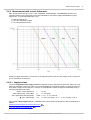
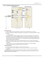
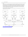
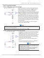
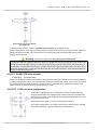
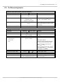
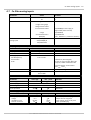
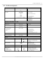
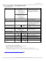
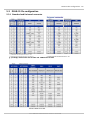
1.1 Guide to Using the Manual
WHERE?
To look for WHAT?
Contents
You should really read the following chapters!
Ch. 1
imc C-SERIES
Guidlines and general notes
Ch. 1
Properties of im C-SERIES
Expansions and differences
Ch. 2
Overview
all devices
Ch. 3
Device description
Description of the C-SERIES devices
Ch. 4
Technical Specifications
Data Sheets
Ch. 4
Connectors
Pin configuration
WHERE?
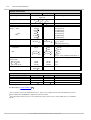
10
26
27
55
136
189
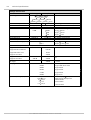
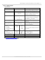
To look for WHAT?
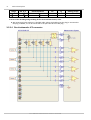
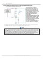
Contents
You should really read the imc DEVICES manual!
Ch. 2
Getting Started
Software installation, requirements, settings, update-info
Ch. 3
Operation
Description of the various menu commands and options
Ch. 4
Field bus
CAN-Bus-Interface, J1587-Bus
Ch. 5
Triggers and Events
Triggered/untriggered measurement, pretrigger, oscilloscope
mode, multi-shot operation
Ch. 6
imc Online FAMOS
Operation and application tips
Ch. 7
Save Options and Directory
Structure
Saving to PC hard disk, saving to the device hard disk, autotrial
mode, autostart mode, stand-alone mode, directory structure
Sample memory requirement estimation
Ch. 8
µ-Disk, PCMCIA Drive
Features of the µ-Disk & Hot-plug
Ch. 9
Network Options
Synchronized start (Ethernet-) net-bits
Ch. 10
Synchronization with DCF77
Workings, connecting
Ch. 11
Display
Operation and Tutorial
Ch. 12
imcMessaging
Automatic generated messages by the devices
Ch. 13
Miscellaneous
Tips and tricks
Regularly updated information and up-to-date user's manuals can be accessed on www.imc-berlin.com.
imc C-SERIE User's Manual Version 2.0 Rev 2 - 03.01.2014
10
imc C-SERIES
1.2 Guidelines
1.2.1 Certificates and Quality Management
imc holds DIN-EN-ISO-9001 certification since May 1995.
You can download an English version of the CE Certification on our Webpage: http://www.imc-berlin.de/
unternehmen/qs/ce-konformitaetserklaerung/. Current certificates and information about the imc
quality system can be found on the Webpage: http://www.imc-berlin.com in section Customer Support.
For further information, please contact our hotline.
1.2.2 imc Guarantee
Subject to imc Meßsysteme GmbH's general terms and conditions.
1.2.3 ElektroG, RoHS, WEEE
The company imc Meßsysteme GmbH is registered under the following number:
WEEE Reg.- # DE 43368136
Brand: imc DEVICES
Category 9: Monitoring and control instruments exclusively for commercial use
Valid as of 24.11.2005
Our products fall under Category 9, "Monitoring and control instruments exclusively for commercial use"
and are thus at this time exempted from the RoHS guidelines 2002/95/EG.
_______________________________________________________
The law (ElektroG) governing electrical and electronic equipment was announced on March 23, 2005 in the German
Federal Law Gazette. This law implements two European guidelines in German jurisdiction. The guideline 2002/95/
EG serves "to impose restrictions on the use of hazardous materials in electrical and electronic devices". In Englishspeaking countries, it is abbreviated as "RoHS" ("Restriction of Hazardous Substances").
The second guideline, 2002/96/EG "on waste electrical and electronics equipment" institutes mandatory acceptance
of returned used equipment and for its recycling; it is commonly referred to as WEEE guidelines ("Waste on Electric
and Electronic Equipment").
The foundation "Elektro-Altgeräte Register" in Germany is the "Manufacturers’ clearing house" in terms of the law
on electric and electronic equipment ("ElektroG"). This foundation has been appointed to execute the mandatory
regulations.
imc C-SERIE User's Manual Version 2.0 Rev 2 - 03.01.2014
Guidelines
1.2.4 Product improvement
Dear Reader!
We at imc hope that you find this manual helpful and easy to use. To help us in further improving this
documentation, we would appreciate hearing any comments or suggestions you may have.
In particular, feel free to give us feedback regarding the following:
Terminology or concepts which are poorly explained
Concepts which should be explained in more depth
Grammar or spelling errors
Printing errors
Please send your comments to the following address:
imc Meßsysteme GmbH
Voltastraße 5
D - 13355 Berlin
Phone:
Fax:
0049 - 30 - 46 70 90 - 26
0049 - 30 - 4 63 15 76
WWW: www.imc-berlin.com
e-mail: [email protected]
imc C-SERIE User's Manual Version 2.0 Rev 2 - 03.01.2014
11
12
imc C-SERIES
1.2.5 Important notes
1.2.5.1 Remarks Concerning EMC
imc C-SERIES satisfies the EMC requirements for unrestricted use in industrial settings.
Any additional devices connected to imc C-SERIES must satisfy the EMC requirements as specified by the
responsible authority (within Europe2) in Germany the BNetzA - "Bundesnetzagentur" (formerly BMPTVfg. No. 1046/84 or No. 243/91) or EC Guidelines 2004/108/EEC. All products which satisfy these
requirements must be appropriately marked by the manufacturer or display the CE certification marking.
Products not satisfying these requirements may only be used with special approval of the regulating
body in the country where operated.
All signal lines connected to imc C-SERIES must be shielded and the shielding must be grounded.
Note
The EMC tests were carried out using shielded and grounded input and output cables with the
exception of the power cord. Observe this condition when designing your experiment to ensure high
interference immunity and low jamming.
Reference
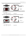
See also General Notes \ Precautions for operation \ Grounding, shielding \ Shielding
2 If you
are located outside Europe, please refer the appropriate EMC standards used in the country of operation.
1.2.5.2 FCC-Note
This equipment has been tested and found to comply with the limits for a Class B digital device, pursuant
to Part 15 of the FCC Rules (CFR 15.105)3. These limits are designed to provide reasonable protection
against harmful interference in a residential installation. This equipment generates, uses, and can radiate
radio frequency energy and, if not installed and used in accordance with the instructions, may cause
harmful interference to radio communications. However, there is no guarantee that interference will not
occur in a particular installation. If this equipment does cause harmful interference to radio or television
reception, which can be determined by turning the equipment on and off, the user is encouraged to try
to correct the interference by one or more of the following measures:
Reorient or relocate the receiving antenna.
Increase the separation between the equipment and the receiver.
Connect the equipment into an outlet on a circuit different from that to which the receiver is
connected.
Consult our imc hotline or an experienced radio or television technician for help.
Modifications
The FCC requires the user to be notified that any changes or modifications made to this device that are
not expressly approved by imc may void the user's authority to operate this equipment.
3FCC
- United States Federal Communications Commission
imc C-SERIE User's Manual Version 2.0 Rev 2 - 03.01.2014
Guidelines
1.2.5.3 Cables
Connections to this device must be made with shielded cables with metallic RFI/EMI connector hoods to
maintain compliance with FCC Rules and Regulations.
1.2.5.4 Other Provisions
Industrial Safety
We certify that imc C-SERIES in all product configuration options corresponding to this documentation
conforms to the directives in the accident prevention regulations in "Electric Installations and Industrial
Equipment" (BGV-A3 of the Index of Accident Prevention Regulations of the Professional Guilds in
Germany).
This certification has the sole purpose of releasing imc from the obligation to have the electrical
equipment tested prior to first use (§ 5 Sec. 1, 4 of BGV-A3). This does not affect guarantee and liability
regulations of the civil code.
_______________________________________________________
* formely VBG-4, refer http://www.bgfe.de
1.3 General Notes
This device has been conceived and designed to comply with the current safety regulations for data
processing equipment (which includes business equipment). If you have any questions concerning
whether or not you can use this device in its intended environment, please contact imc or your local
distributor.
The measurement system has been carefully designed, assembled and routinely tested in accordance
with the safety regulations specified in the included certificate of conformity and has left imc in perfect
operating condition. To maintain this condition and to ensure continued danger-free operation, the user
should pay particular attention to the remarks and warnings made in this chapter. In this way, you
protect yourself and prevent the device from being damaged.
Read this manual before turning the device on for the first time! Pay attention to any additional
information pages pertaining to the pin configuration etc. which may have been included with this
manual.
Warning
Before touching the device sockets and the lines connected to them, make sure static electricity is
drained. Damage arising from electrostatic discharge is not covered by the warrantee.
1.3.1 Instruction manual
This instruction manual provides important notes on using the device. The safe working is conditional on
compliance with all safety measures and instruction specified.
Additionally, all accident prevention and general safety regulations pertinent to the location at which the
device is used must be adhered to.
This instruction manual exclusively describes the device, not how to operate the imc software ! The
instructions for the imc measurement software are provided in their own manual. Read carefully the
manual before beginning any work!
imc C-SERIE User's Manual Version 2.0 Rev 2 - 03.01.2014
13
14
imc C-SERIES
1.3.2 Liability limitations
All specifications and notes in the operating instruction manual are subject to applicable standards and
regulations, and reflect the state of the art well as accumulated years of knowledge and experience.
The manufacturer declines any liability for damage arising from:
failure to comply with the instructions provided,
inappropriate use of the equipment,
additionally, the general terms and conditions of the company imc Mess-Systeme GmbH apply.
1.3.3 Guarantee
Each device is subjected to a 24-hour "burn-in" before leaving imc. This procedure is capable of
recognizing almost all cases of early failure. This does not, however, guarantee that a component will not
fail after longer operation. Therefore, all imc devices are guaranteed to function properly for two years.
The condition for this guarantee is that no alterations or modifications have been made to the device by
the customer. Unauthorized intervention in the device renders the guarantee null and void.
1.3.4 Before starting
Condensation may form on the circuit boards when the device is moved from a cold environment to a
warm one. In these situations, always wait until the device warms up to room temperature and is
completely dry before turning it on. The acclimatization period should take about 2 hours. This is
especially recommended for devices without ET (extended environmental temperature range).
We recommend a warm-up phase of at least 30 min prior to measure.
Existing ventilation slits must be kept unimpeded to avoid heat buildup in the device interior.
The devices have been designed for use in clean and dry environments. It is not to be operated in 1)
exceedingly dusty and/ or wet environments, 2) in environments where danger of explosion exists nor 3)
in environments containing aggressive chemical agents.
1.3.5 Notes on maintenance and servicing
No particular maintenance is necessary.
The specified maximum errors are valid for 1 year following delivery of the device under normal
operating conditions (note ambient temperature!).
There are a number of important device characteristics which should be subjected to precise checking at
regular intervals. We recommend annual calibration. Our calibration procedure includes calibration of
inputs (checking of actual values of parameters; deviations beyond tolerance levels will be reported), a
complete system-checkup, newly performed balancing and subsequent calibration (the complete
protocol set with measurement values is available at an extra charge). Consult our Hotline for the price
for system calibration according to DIN EN ISO 9001.
For devices with UPS functions, we recommend maintenance every 2-3 years.
Please note the hints for rechargeable batteries.
When returning the device in connection with complaints, please include a written, outlining description
of the problem, including the name and telephone number of the sender. This will help expedite the
process of problem elimination.
For questions by telephone please be prepared to provide your device's serial number and have your imc
installation software, as well as this manual at hand, thanks !
The serial number, necessary power supply, interface type and software version included can be
imc C-SERIE User's Manual Version 2.0 Rev 2 - 03.01.2014
General Notes
determined from the plaque on the side of the device.
1.3.6 Safety
This section provides an overview of all important aspects of protection of personnel for reliable and
trouble-free operation.
Failure to comply with the instructions and protection notes provided here can result in serious danger.
1.3.6.1 Responsibility of the user
The device is for use in commercial applications. The user is therefore obligated to comply with legal
regulations for work safety.
Along with the work safety procedures described in this instruction manual, the user must also conform
to regulations for safety, accident prevention and environmental protection which apply to the work site.
The user must also ensure that any personnel assisting in the use of the device have also read and
understood the instruction manual.
1.3.6.2 Operating personnel
Warning
Danger of injury due to inadequate qualifications!
Improper handling may lead to serious damage to personnel and property. When in doubt, consult
qualified personnel.
Work which may only be performed by trained imc personnel may not be performed by the user. Any
exceptions are subject to prior consultation with the manufacturer and are conditional on having
obtained corresponding training.
The instruction manual distinguishes the following degrees of qualification for performing various
actions:
Users of the measurement equipment. Fundamentals of measurement engineering.
Recommended: knowledge of foundations of electrical engineering. Familiarity with the Microsoft
Windows operating system. Users may not open or modify the device.
Qualified personnel is able, due to training in the field and to possession of skills, experience and
familiarity with the relevant regulations, to perform work assigned while independently recognizing
any hazards.
imc C-SERIE User's Manual Version 2.0 Rev 2 - 03.01.2014
15
16
imc C-SERIES
1.3.6.3 Special dangers
This segment states what residual dangers have been identified by the hazard analysis.Observe the
safety notes listed here and the warnings appearing in subsequent chapters of this manual in order to
reduce health risks and to avoid dangerous situations.
Warning
DANGER!
Lethal danger from electric current!
Contact with conducting parts is associated with immediate lethal danger. Damage
to the insulation or to individual components can be lethally dangerous.
Therefore:
In case of damage to the insulation, immediately cut off the power supply and
have repair performed.
Work on the electrical equipment must be performed exclusively by expert
electricians.
During all work performed on the electrical equipment, it must be deactivated and
tested for static potential.
Warnung
DANGER!
Injuries from hot surfaces!
Devices from imc are designed so that their surface temperatures do not exceed
limits stipulated in EN 61010-1 under normal conditions.
Therefore:
Handles are provided in order to ensure safe operation (for imc CRONOSflex
systems the handles must be "clicked" the devices).
Surfaces whose temperature can exceed the limits under circumstances are
denoted by the symbol shown at left.
imc C-SERIE User's Manual Version 2.0 Rev 2 - 03.01.2014
General Notes
1.4 Transport and storage
1.4.1 After unpacking ...
Check the delivered system immediately upon receiving it for completeness and for possible transport
damage.
In case of damage visible from outside, proceed as follows:
Do not accept the delivery or only accept it with reservations
Note the extent of the damage on the packing documents or on the delivery service's packing list.
Begin the claims process.
Please check the device for mechanical damage and/ or loose parts after unpacking it. The supplier must
be notified immediately of any transportation damage! Do not operate a damaged device!
Check that the list of accessories is complete:
230/110 V AC/DC-supply unit with mains cable
Printed imc C-SERIES Manual - Getting started
Manufacturer's Calibration Certificate
1x crossed Ethernet network cable and 1 x uncrossed
1x LEMO connector (ACC/Power-Plug-1)
optional: removable hard drive (µ-Disk), GPS receiver, etc.
DSUB-15 Connectors:
1x ACC/DSUB(M)-DI4-8, 15-pin DSUB clamp connector for 8 digital inputs
1x ACC/DSUB(M)-DO8, 15-pin DSUB clamp connector for 8 digital outputs
1x ACC/DSUB(M)-ENC4, 15-pin DSUB clamp connector for 4 incremental counter inputs
1x ACC/DSUB(M)-DAC4, 15-pin DSUB clamp connector for 4 analog outputs
Connector set corresponding to the device's built-in amplifier (see corresponding data sheet)
Note
File a claim about every fault as soon as it is detected. Claims for damages can only be honored within
the stated claims period.
1.4.2 Transporting the device
When transporting the device, always use the original packaging or a appropriate packaging which
protects the device against knocks and jolts. If transport damages occur, please be sure to contact the
imc Customer Support. Damage arising from transporting is not covered in the manufacturer's
guarantee.
Potential damage from condensation can be limited by wrapping the device in plastic foil. On this topic,
see also the notes under Before commissioning Before starting 14 .
1.4.3 Storage
As a rule, the measurement device can be stored at temperatures ranging from -20 to +85°C. Also
observe manufacturer’s instructions pertaining to any optional accessories such as internal hard drive,
Display, etc.
imc C-SERIE User's Manual Version 2.0 Rev 2 - 03.01.2014
17
18
imc C-SERIES
1.4.4 Cleaning
Always unplug the power supply before cleaning the device. Only qualified service technicians are
permitted to clean the housing interior.
Do not use abrasive materials or solutions which are harmful to plastics. Use a dry cloth to clean
the housing. If the housing is particularly dirty, use a cloth which has been slightly moistened in a
cleaning solution and then carefully wrung out. To clean the corners, slits etc. of the housing, use a
small soft dry brush.
Do not allow liquids to enter the housing interior.
Be certain that the ventilation slits remain unobstructed.
1.5 Precautions for operation
Certain ground rules for operating the system, aside from reasonable safety measures, must be observed
to prevent danger to the user, third parties, the device itself and the measurement object. These are the
use of the system in conformity to its design, and the refraining from altering the system, since possible
later users may not be properly informed and may ill-advisedly rely on the precision and safety promised
by the manufacturer.
If you determine that the device cannot be operated in a non-dangerous manner, then the device is to
be immediately taken out of operation and protected from unintentional use. Taking this action is
justified under any of the following conditions:
I. the device is visibly damaged,
II. loose parts can be heard within the device,
III.the device does not work
IV.the device has been stored for a long period of time under unfavorable conditions (e.g. outdoors
or in high-humidity environments).
1. Observe the data in the chapter "Technical Specifications", to prevent damage to the unit through
inappropriate signal connection.
2. Note when designing your experiments that all input and output leads must be provided with
shielding which is connected to the protection ground ("CHASSIS") at one end in order to ensure
high resistance to interference and noisy transmission.
3. Unused, open channels (having no defined signal) should not be configured with sensitive input
ranges since otherwise the measurement data could be affected. Configure unused channels with a
broad input range or short them out. The same applies to channels not configured as active.
4. For measurement of voltages >60 V, only use banana jacks (4 mm) with contact protection.
5. If you are using a internal device drive, observe the notes in the imc DEVICES / imc STUDIO manual.
Particular care should be taken to comply with the storage device’s max. ambient temperature
limitation.
6. Avoid prolonged exposure of the device to sunlight.
1.5.1 Grounding, shielding
In order to comply with Part 15 of the FCC-regulations applicable to devices of Class B, the system must
be grounded.
imc C-SERIE User's Manual Version 2.0 Rev 2 - 03.01.2014
Precautions for operation
1.5.1.1 Devices with non-isolated power supply
CS Devices
and the CL-2108
except CS-8008[-N]
The DC-supply input on the device itself (LEMO-plug, female) is not
galvanically isolated from the housing (CHASSIS):
-SUPPLY input is galvanically connected to CHASSIS internally.
That means the device's internal power supply circuitry comprises
non-isolating DC/DC converter.
1.5.1.2 Devices with isolated power supply
CL Devices
and the CS-8008
except CL-2108[-N]
The DC-supply input on the device itself (LEMO-plug, female) is
galvanically isolated from the housing (CHASSIS):
-SUPPLY input is not connected to CHASSIS internally.
That means the decive's internal power supply circuitry comprises
isolating DC/DC converter.
If the device is powered by an isolated DC-voltage source (e.g. battery),
use the device’s black grounding socket (“CHASSIS”) or the LEMO supply
cable’s shielding to ground the device.
1.5.1.2.1 Grounding with the use of the included power adapter
imc CL Devices and the CS-8008[-N] (exception: CL-2108[-N]
19 )
Use of the included table-top power adapter is protected by the power plug's protection ground
connection: at the adapter's LEMO terminal, both the (-) pole of the supply voltage as well as the
shielding and connector pod are connected with the power cable's protection ground.
1.5.1.2.2 Grounding with power supplied by a car battery
imc CL Devices and CS-8008[-N] (exception: CL-2108[-N]
19 ) with isolated DC-supply (e.g. battery)
If the power supply (e.g. car battery) and the measurement device are at different voltage levels, then if
they were connected by the supply line, it would cause a ground loop. For such cases, the isolated
internal device power supply ensures separation of the two voltage levels. The ground reference for the
imc C-SERIE User's Manual Version 2.0 Rev 2 - 03.01.2014
19
20
imc C-SERIES
measurement device must then be established in a separate step.
For running on an isolated DC power supply source (e.g. battery), either the grounding socket terminal, a
grounding contact on the device ("CHASSIS"), or the CHASSIS contact on the imc signal connectors must
be used.
Isolated power inputs avoids ground loops in distributed topologies
With stationary installations and the use of (already isolated) AC/DC adapters, any system ground
differentials between the device and the central or local power supplies may not be relevant. The big
issue in such a case, in contrast to mobile, in-vehicle applications, is from where to obtain a reliable
ground voltage. Since it is convenient to use the AC power supply’s protection ground line as the ground
voltage, the LEMO-terminated AC/DC adapters for imc measurement devices are designed so that the
protection ground line is connected all the way through to the LEMO connector’s housing, thus securing
the device’s voltage level to protection ground. Additionally, in the AC/DC-adapter’s LEMO-terminal (not
the device’s LEMO-socket!), the reference ground of the power adapter is connected with the housing’s
(CHASSIS) protection ground: Since the AC/DC power adapter is already isolating, as is the power input,
this supply voltage’s reference would not initially be defined and can be set arbitrarily. In particular for
reasons of suppressing HF (high-frequency) interference signals stemming from the AC/DC switching
power adapter, direct grounding is normally advisable.
1.5.1.3 Shielding
Also, all signal leads to the device must be shielded and the shielding grounded (electric contact
between the shielding and the plug housing "CHASSIS").
To avoid compensation currents, always connect the shielding to one side (potential) only.If the imc
DSUB block screw terminal plug is used, the shielding should be connected to the pull-relief clamp on the
cable bushing. This part of the conductor-coated plastic plug housing has electrical contact to the
device's housing, just as Terminals 15 and 16 (labeled: "CHASSIS", to the left and right of the imc-plug
cable bushing) do; but is preferable to the "CHASSIS" terminals for optimum shielding.
1.5.1.4 Potential difference with synchronized devices
Note
When using multiple devices connected via the SYNC plug for synchronization purposes, ensure that all
devices are at the same voltage level. Any potential differences among devices may have to be evened
out using an additional line having adequate cross section.
If the synchronized devices are at different voltage levels, they should be compensated by means of a
lead having the appropriate cross-section. If the SYNC plug at your device is equipped with a yellow ring
it is already isolated and it is protected against potential differences (concerning devices as of summer
2012).
Alternatively it is possible to isolate the devices by using the module ISOSYNC, see also chapter
Synchronization in the imc STUDIO / imc DEVICES manual.
imc C-SERIE User's Manual Version 2.0 Rev 2 - 03.01.2014
Precautions for operation
1.5.2 Power supply
Differences between devices of the C-SERIES with serial number (s/n) >14000 [-N] and devices with s/n <
14000 are stated here.
The device is powered by a DC-supply voltage which is supplied via a 2-pin LEMO-plug.
Type designation LEMO plug:
Device
CS
CL
CX
LEMO plug type designation
FGG.1B.302 CLAD 76
FGG.0B.302 CLAD 52ZN
FGG.2B.302.CLAD62Z
Size
(middle)
(small)
(big)
The permissible supply voltage range is 10 ... 32V (DC). The product package includes a corresponding
desktop supply unit (15 V DC) as an AC-adapter for mains voltage (110 .. 240V 50/60Hz).
Note
Please note, that the operation temperature of the desktop supply is prepared for 0°C to 40°C, even if
your measurement devices is designed for extended temperature range!
The package also includes a cable with a ready-made LEMO-plug which can be connected to a DC-voltage
source such as a car battery. When using this, note the following:
Grounding of the device must be ensured. If the power supply unit comes with a grounding line, it
would be possible to ground the system "by force", by making a connection from this line to the
plug enclosure (and thus to the device ground). The table-top power supply unit is made to allow
this.
This manner of proceeding may not be desirable because it may be desirable to avoid transient
currents along this line (e.g. in vehicles). In this case the ground-connection must be made to the
device directly. For this purpose a (black) banana jack ("CHASSIS") is provided.
The feed line must have low resistance, the cable must have an adequate cross-section. Any
interference-suppressing filters which may be inserted into the line must not have any series
inductor greater than 1mH. Otherwise an additional parallel-capacitor is needed.
Pin configuration:
+Supply
LEMO-Plug
(inside view on
soldering pins)
-Supply
FGG.1B.302.CLAD76
FGG.0B.302.CLAD52ZN
FGG.2B.302.CLAD62Z
The +pin is marked with a red dot
imc C-SERIE User's Manual Version 2.0 Rev 2 - 03.01.2014
21
22
imc C-SERIES
1.5.2.1 Main switch
CS device
CS-8008[-N]
CX device
CL Device
With the exception of the CS-8008[-N], the main switch of all CS-devices takes the form of a flip switch.
The main switch of the CL-devices and of the CS-8008[-N] takes the form of a rocker switch, which
activates the device when it is tipped for approx. 1 second in the "ON" direction.
With the CX devices, a power-On button with a built-in power-LED is the main switch. During operation,
the LED shines green. In response to deactivation, and whenever the supply voltage falls below the
minimum (power fail), the LED flashes.
Activation
Devices with rocker switch will be activated by clicking for approx. 1 sec the "ON" position. Devices
with flip switch will be activated by setting the main switch to the "I" position.
Successful "booting" of the device is confirmed by three short beeps.
CS- and CX-devices: Upon activation, all 6 status LEDs blink twice.
CL-devices: There are no LEDs in this device type. Instead the start procedure is seen on the display.
The device is activated
CS-devices indicate the activated state by the Power LED shining. With a CX-device, the built-in LED
shines in the main switch.
CL-devices indicate the activated state by the Display being on.
Deactivation
Devices with rocker switch will be deactivated by clicking for approx. 1 sec the "OFF" position. Devices
with flip switch will be deactivated by setting the main switch to the "O" position.
If the device is running a measurement, it does not deactivate immediately. First, any associated files
are closed on the internal hard drive before the device switches off automatically. This process lasts
for a maximum of about 10sec. It is not necessary to hold the main switch down for this duration!
CS-devices: The deactivation procedure changes the color of the Power LED.
imc C-SERIE User's Manual Version 2.0 Rev 2 - 03.01.2014
Precautions for operation
CX-devices: The deactivation procedure is indicated by regular flashing of the "POWER"-LED.
CL-devices: The deactivation procedure itself is not indicated. After 10s, the device is completely
deactivated and the display switches off.
1.5.2.2 Remote control of the main switch
Alternatively to the manual main switch on the device's front panel, it is possible to switch the device on
and off by means of an electrical remote control contact. The terminal designated "REMOTE" on the
device's rear panel makes this available: either brief or longer connection of the signals "SWITCH" and
"ON" activates the device, connecting "SWITCH" with "OFF" switches it off. For the CS-8008, a DSUB-15
socket is the connector, while for CL devices and CX-5032 a LEMO socket is the connector (6-pin
FGG.0B.306.CLAD.52Z).
PIN configuration of LEMO plug (FGG.0B.306.CLAD.52Z 6-polig) for CX- and CL
LEMO
Signal
LEMO
Signal
1
OFF
4
SWITCH1
2
SWITCH
5
3
ON
6
-BATT (internal testpin)
-
PIN configuration of the DSUB-15 plug (female) for CS-8008[-N]
DSUB-15
9
2
10
Signal
OFF
SWITCH
ON
DSUB-15
3
11
Signal
SWITCH1
-BATT (internal testpin)
The signal " SWITCH1" serves to run the device with the switch
permanently bridged: when "ON" and "SWITCH1" are connected, the
device starts as soon as an external supply voltage is provided.
If this supply is interrupted, the UPS keeps the device activated for the
appropriate buffer duration in order to close the measurement and files,
and then the device deactivates itself. Starting the device on the internal
battery isn't possible in this configuration, but once it has started the
device can run on the battery as a backup.
This type of operation is specially designed for use in a vehicle,
permanently coupled to the ignition and not requiring manual control.
Any switch or relay contact used for this purpose must be able to bear a current of approx. 50 mA at 10
W max. The reference voltage for these signals is the primary voltage supply.
Possible configurations:
Function
Switch on "normal"
Switch on when connected to main supply only Þ "jumpered main switch "
Switch off (switch off within 10 s)
Pin configuration of the REMOTE plug
193
.
imc C-SERIE User's Manual Version 2.0 Rev 2 - 03.01.2014
Jumper between
SWITCH and ON
SWITCH1 and ON
SWITCH and OFF
23
24
imc C-SERIES
1.5.3 UPS
Devices with DC supply input are equipped with an uninterruptible power supply (UPS). This allows for a
continuous operation unaffected by temporary short-term outage of the main power supply. This type of
operation is particularly useful for operation in a vehicle, permanently attached to starter lock and main
power switch and thus not requiring manual control. Activation of UPS buffering is indicated by the
power control LED (PWR) changing from green to yellow. With many imc measurement devices, active
UPS buffering is additionally indicated by an acoustic buzzer signal.
The UPS provides backup in case of power outage and monitors its duration. If the power outage is
continuous and if it exceeds the specific device’s “buffer time constant”, the device initiates an
automatic shutdown sequence, which equals manual shutdown procedure: Any current active
measurement is automatically stopped, data storage on flash card or internal harddisk is completed by
securely closing all data files, and finally the device is actually switched off. This entire process may take
a couple of seconds.
Thus, a typical application of this configuration is in vehicles, where the power supply is coupled to the
ignition. A buffer is thus provided against short-term interruptions. And on the other hand, deep discharge
of the buffer battery is avoided in cases where the measurement system is not deactivated when the
vehicle is turned off.
If the power failure is not continuous but only temporary, the timer that monitors blackout duration is
reset every time the main supply has returned to valid levels. The buffer time constant is a variable
device parameter that can be configured according to system size and battery capacity. It can usually be
written into the device under software control and is preconfigured to reasonable default values upon
delivery (see description in the software manual).
1.5.3.1 Buffering time constant and maximum buffer duration
The buffer time constant is a permanently configurable device parameter which can be selected as a
order option. It sets the maximum duration of a continuous power outage after which the device turns
itself off.
The maximum buffer duration is the maximum (total) time, determined by the battery capacity, which the
device can run on backup. This refers to cases where the self-deactivation is not triggered; e.g., in case of
repeated short-term power-interruptions. The maximum buffer duration depends on the battery's current
charge, on the ambient temperature and on the battery's age. The device automatically deactivates itself
just in time to avoid deep discharge of the battery.
Note
The buffer time constant can be changed using the operating software imc DEVICES or imc STUDIO.
see imc DEVICES manual:
Chapter 3: Operation > User Interface > Device - menu >Properties...: Entry UPS
1.5.3.2 Charging power
The charging power depends on the device type, its hardware configuration, and the amount and type of
rechargeable batteries installed. For this reason, there are a variety of combinations with charging power
between 2.4 W and 16 W.
1.5.3.3 Take-over threshold
The voltage threshold at which the storage battery takes over the power supply from the external source is
approx. 9.75 V (8.1 V for CS). The take-over procedure is subjected to an hysteresis to prevent oscillating
take-over. This would be caused by the external supply's impedance. This inevitable impedance lets the
external supply rise again, right after take-over to internal buffering. Hysteresis in the take-over threshold
will prevent oscillations due to this effect. If, during supply from of the buffering battery, the external supply
imc C-SERIE User's Manual Version 2.0 Rev 2 - 03.01.2014
Precautions for operation
voltage rises as high as 10.9 V (9 V for CS), the external voltage takes over again from the buffering
battery.
If you check these thresholds, note that when the supply voltage is overlaid with a high frequency
interference or ripple-voltage, the minima are of key importance. In fact, the overlying interference could be
caused by feedback from the device itself!
Note
The voltage specification refers to the device terminals. Please consider the voltage drop of the
supply line, when determining the voltage supply.
During activation the supply voltage must be above the upper take-over threshold ( 11 V).
1.5.4 Rechargeable accumulators and batteries
1.5.4.1 Lead-gel batteries
Devices which come with the optional UPS-Function contain maintenance-free lead-gel batteries.
Charging these internal backup batteries is accomplished automatically when the activated device
receives a supply voltage. Due to the inevitable leakage of charge we recommend that the device be
activated for 6 to 9 hours at least every 3 months to prevent the batteries from dying. In case the UPS is
used a lot (many discharge and recharge cycles), the life time depends on how much (deep) it has been
discharged (is the UPS buffering only for a short time or is the UPS discharged completely every time?).
The manufacturer specifies 200 cycles @100% discharging and 1200 cycles @ 30% and 25°C ambient
temperature. (that should be true in general for all Pb batteries.)
Note
imc recommend maintenance every 2-3 years.
Do not throw the lead-gel accumulators in the household garbage.
1.5.5 Fuses (polarity-inversion protection)
The device supply input is equipped with maintenance-free polarity-inversion protection. No fuses or
surge protection is provided here. Particularly upon activation of the device, high current peaks are to be
expected. When using the device with a DC-voltage supply and custom-designed supply cable, be sure to
take this into account by providing adequate cable cross-section.
imc C-SERIE User's Manual Version 2.0 Rev 2 - 03.01.2014
25
26
imc C-SERIES
Properties of the imc C-SERIES
The imc C-SERIES consists of smart network-capable, unventilated compact measurement devices for allpurpose measurement of physical quantities. These devices can operate either in computer-aided or
autonomous mode and are lightweight, compact, and robust, thus, especially well adapted to
applications in R&D or in the testing of mechanical and electromechanical components of machines, on
board vehicles, or in monitoring tasks in installations.
The most important differences/enhancements of the new devices with the ID code “-N” (suffix) involve
functions for networking environments.
Highlights:
Support of data storage on a network drive (NAS device, hard drive on a network server)
Can be equipped with a fixed internal WiFi-adapter (Wireless Network, W-LAN)
Supports synchronization of multiple devices via network protocol NTP (Network Time Protocol),
which then replaces the dedicated SYNC-line
Standard equipped with built-in isolated SYNC signaling (uniformly BNC connectors!), which
facilitates operation of multiple devices in distributed setups where ground loops are to be
expected, thus in device networking.
Improved synchronization clock tracking (especially in cases of interrupted GPS reception)
Differences:
new device group 5 (to date device group 3)
device serial number range: 14xxxx
direct CF Card Slot, statt bisher PCMCIA mit mechanischem CF Adapter
The new „-N“ devices now allow fixed installation of an internal W-LAN adapter, offering the following
features/advantages:
rugged solution with robust antenna connection (SMB) tot he device’s front panel suited either for
direct antenna connection or cable to independently installed antenna
simultaneous use of W-LAN and on onboard storage
supports IEEE 802.11g with 54 Mbit/s transfer rate
extended temperature range of: -30 .. +85°C
Synchronization
The new „-N“ devices are uniformly equipped with BNC.
Master-Slave synchronization of multiple devices is now more robust and particularly simplified in
environments where ground loops are prevalent such as in spatially widely distributed installations: the
“-N” devices now come standard with internal galvanical isolation for the SYNC-signal. A yellow marking
of the BNC terminal connection indicates isolation of the SYNC signal.
Find here a overview of significant differences
169
imc C-SERIE User's Manual Version 2.0 Rev 2 - 03.01.2014
27
2.1 Device Overview
The following table shows all devices. Some of the capabilities discussed in this manual only pertain to
certain device models. To see which capability profile your device represents, refer to this table.
—
Device
Interface
protocol / Bit/s
Std./
MBit/s
Optional
Data carrier
CF**
•
not available
PCMCIA
Hard
drive
RAM
Data/
Interface
ο
standard
Rate *
optional
Short
description
Distinguishing
characteristics
scanner system with
optional amplifiers,
DAC, DIO
CAN data logger with
2,4 or 6 nodes
scanner system with
isolated amplifier,
DIO (CAN)
housing
Group 1
imc µ-MUSYCS
NetBEUI/
TCP/IP
10
—
512MB
FAT16
—
1,6 MB/
64 KB
80 kHz
imc BUSDAQ
10
—
—
—
7,6 MB/
64 KB
7,6 MB/
64 KB
80 kHz
10
512MB
FAT16
512MB
FAT16
—
imc SPARTAN-L,
imc SPARTAN-S
NetBEUI/
TCP/IP
NetBEUI/
TCP/IP
imc CRONOS-PL
TCP/IP
10
—
512MB
FAT16
—
7,6 MB/
8 MB
200 kHz
modular system
(SPBBF) dated up till
Summer, 2003
production date;
no LEDs at Ethernet
terminal,
SN12XXXX
400 kHz
modular system
(DAB4K) as of
Summer, 2003
Production date;
two active LEDs at
Ethernet terminal,
SN12XXXX
400 kHz
non modular system
housing,
markings,
SN12XXXX
20 kHz
housing
housing,
markings
Group 2
imc CRONOS-PL
-2, -3,-4, -8,
-13, -16
imc CRONOS-SL
-2, -4
TCP/IP
100
imc C1
imc C-SERIES
TCP/IP
100
—
•
•
14 MB/
16 MB
(32 MB from
2007
Group 3
—
•
—
14 MB/
32 MB
Group 1: data access from PC to internal data carrier via the File Manager in imc DEVICES
Group 2-3:data access from PC to internal data carrier via Microsoft Explorer.
* Max.aggregate sampling rate
** We recommend storage media that are tested by imc (please consider the hotline for a current list)
imc C-SERIE User's Manual Version 2.0 Rev 2 - 03.01.2014
28
Properties of the imc C-SERIES
Device table, continued
Device
—
Interface
protocol / Bit/s
Std.
MBit/s
Data carrier
CF**
•
not available
PCMCIA
Hard
drive
RAM
Data/
Interface
ο
standard
optional
Rate *
Short
description
Distinguishing
characteristics
housing,
markings,
SN13XXXX
housing,
markings,
SN13XXXX
Group 4
imc BUSDAQ II
TCP/IP
100
•
—
ο
16 MB/
32 MB
400 kHz
field bus data logger
imc SPARTAN
TCP/IP
100
•
—
ο
16 MB/
32 MB
400 kHz
modular system
imc SPARTAN-R
TCP/IP
100
•
—
ο
16 MB/
32 MB
400 kHz
modular system
imc CRONOS
compact-400, Base
Unit
imc CRONOS
flex-400
TCP/IP
100
•
—
ο
16 MB/
32 MB
400 kHz
modular system
imc miniPOLARES
TCP/IP
100
•
—
—
16 MB/
32 MB
400 kHz
non modular system
imc C1
imc C-SERIES
TCP/IP
100
•
—
—
16 MB/
32 MB
400 kHz
non modular system
Rate *
Short
description
Distinguishing
characteristics
modular system
housing,
markings,
SN16XXXX
Group 5
Device
Interface
protocol / Bit/s
Std.
MBit/s
TCP/IP
100
Data carrier
USB**
Express
Card
Hard
drive
RAM
Data/
Interface
housing,
markings,
SN14XXXX
housing,
markings,
SN14XXXX
housing,
markings,
SN14XXXX
housing,
markings,
SN14XXXX
Group 6
Base Unit
imc CRONOS
flex-2000
•
•
ο
16 MB /
512 MB
2 MHz via
EtherCAT
else
400 kHz
Group 4-6:
For the purpose of onboard data storage, devices within those groups, are equipped with CF-Card,
ExpressCard slot.
Devices within those groups can be equipped with an internally fixed hard drive available as an option.
Data access from PC to internal data storage media via Microsoft Explorer.
* Max.aggregate sampling rate
** We recommend storage media that are tested by imc (please consider the hotline for a current list)
2.2 Operating software imc DEVICES and imc STUDIO
imc BUSDAQ, imc SPARTAN, imc C-SERIES and measurement devices from the imc CRONOS-series
is operated using the operating software imc DEVICES or imc STUDIO. The operating software enables
complete manual and automatic setting of the measurement parameters, real-time functions, trigger
machines and data saving modes. Display of measurement plots in the curve window and, as well as
experiment documentation in the Report Generator, are integral elements of the software. There are
extensive triggering options and data storage options adapted to particular applications. Together with
the supplementary software imc Online FAMOS, the raw data can be processed in real time to yield
the result data in the desired format, and can be displayed.
imc CANSAS modules can be configured directly from the operating software if the imc CANSAS
software is on the same computer. A separate connection from the imc CANSAS module to the PC, e.g.
imc C-SERIE User's Manual Version 2.0 Rev 2 - 03.01.2014
Operating software imc DEVICES and imc STUDIO
via a USB-CAN adapter, is not necessary.
For special tasks such as system integration in test rigs, there are comfortable interfaces for all
common programming languages like Visual Basic ™, Delphi ™ or LabVIEW.
2.3 Sampling interval
Among the system's physical measurement channels, up to two different sampling times can be in use.
For the possible sampling time see the technical specification in this manual. The aggregate sampling
rate of the system is the sum of the sampling rates of all active channels.
The sampling rates of the virtual channels computed by Online FAMOS do not contribute to the sum
sampling rate. Along with the (maximum of) two "primary" sampling rates, the system can contain
additional "sampling rates" resulting from the effects of certain data-reducing Online FAMOS-functions
(ReductionFactor RF).
There is one constraint when selecting two different sampling rates: Two sampling rates having the ratio
2:5 and lower than 1ms are not permitted (e.g. 200 µs and 500 µs).
2.4 TEDS
imc Plug & Measure is based on the TEDS technology set out in IEEE 1451.4. It fulfills the vision of quick
and error-free measurement even by inexperienced use.
TEDS stands for Transducer Electronic Data Sheet and amounts to a spec sheet containing information
about a sensor, a measurement location and the measurement technology used. It is stored in a memory
chip which is permanently attached to the sensor, and can be read and processed by the measurement
equipment. Besides this, the memory also include a number (unique ID) by which the sensor can be
uniquely identified.
A TEDS sensor or a conventional
sensor equipped with a sensor
recognition memory unit is connected
to the device. The sensor recognition
contains a record of the sensor’s data
and the measurement device settings.
The device reads this info and sets
itself accordingly.
An incorrectly measurement channel is then recognized automatically and marked in different colors. The
meaning of the colors is described in manual imc DEVICES chapter Operation
Settings
Configuration
Sensor TEDS.
imc C-SERIE User's Manual Version 2.0 Rev 2 - 03.01.2014
29
30
Properties of the imc C-SERIES
2.5 Specific parameters
There are a number of other parameters to be set which pertain to the specific (analog) conditioning of
the measurement channels, and thus come with different (and different amounts of) options to select,
depending on the channel group involved. The options are:
Input range: a variety of ranges depending on the channel type
Sensor supply
Filter frequency: low-pass filtering or automatic anti-aliasing filter, corner frequency or options
particular to channel type
Linearization: for thermocouples and PT100 thermistors(for C-41xx and C-70xx)
2.6 Measurement types
2.6.1 Temperature measurement
Temperature measurements can be performed by CS/CL-41xx and CS/CL-70xx
Two methods are available for measuring temperature.
Measurement using a Pt100 requires a constant current, e.g. of 250 µA to flow through the sensor. The
temperature-dependent resistance causes a voltage drop which is correlated to a temperature according
to a characteristic curve.
In measurement using thermocouples, the temperature is determined by means of the electrochemical
series of different alloys. The sensor produces a temperature-dependent potential difference from the
terminal in the CAN connector pod. To find the absolute temperature, the temperature of the terminal
point must be known. For the Pt1000 this is measured directly in the terminal pod, and therefore an
additional type of connector pod is needed.
The voltage coming from the sensor will be converted into the displayed temperature using the
characteristic curves according temperature table IPTS-68.
Note on making settings with imc DEVICES
A temperature measurement is a voltage measurement whose measured values are converted to
physical temperature values by reference to a characteristic curve. The characteristic curve is
selected from the Base page of the imc DEVICES configuration dialog. Amplifiers which enable bridge
measurement (e.g.Cx-70), must first be set to Voltage mode (DC), in order for the temperature
characteristic curves to be available on the Base page.
imc C-SERIE User's Manual Version 2.0 Rev 2 - 03.01.2014
Measurement types
2.6.1.1 Thermocouples as per DIN and IEC
The following standards apply for the thermocouples, in terms of their thermoelectric voltage and
tolerances:
Thermocouple
Symbol
max. temp.
Defined up to
(+)
(-)
DIN IEC 584-1
Iron-constantan (Fe-CuNi)
J
750°C
1200°C
black
white
Copper-constantan (Cu-CuNi)
T
350°C
400°C
brown
white
Nickel-chromium-Nickel (NiCr-Ni)
K
1200°C
1370°C
green
white
Nickel-chromium-constantan (NiCr-CuNi)
E
900°C
1000°C
violet
white
Nicrosil-Nisil (NiCrSi-NiSi)
N
1200°C
1300°C
red
orange
Platinum-Rhodium-platinum (Pt10Rh-Pt)
S
1600°C
1540°C
orange
white
Platinum-Rhodium-platinum (Pt13Rh-Pt)
R
1600°C
1760°C
orange
white
Platinum-Rhodium-platinum (Pt30Rh-Pt6Rh)
B
1700°C
1820°C
n.a.
n.a.
DIN 43710
Iron-constantan (Fe-CuNi)
L
600°C
900°C
red
blue
Copper-constantan (Cu-CuNi)
U
900°C
600°C
red
brown
If the thermo-wires have no identifying markings, the following distinguishing characteristics can help:
Fe-CuNi: Plus-pole is magnetic
Cu-CuNi: Plus-pole is copper-colored
NiCr-Ni: Minus-pole is magnetic
PtRh-Pt: Minus-pole is softer
The color-coding of compensating leads is stipulated by DIN 43713. For components conforming to IEC
584: The plus-pole is the same color as the shell; the minus-pole is white.
2.6.1.2 Pt100 (RTD) - measurement
Aside from thermocouples, RTD (Pt100) units can be directly connected in 4-wire-configuration (Kelvin
connection). An additional reference current source feeds a chain of up to 4 sensors in series.
With the imc Thermo connector, the connection terminals are already wired in such a way that this
reference current loop is closed "automatically".
If fewer than 4 Pt100 units are connected, the current-loop must be completed by a wire jumper from
the "last" RTD to -I4.
If you dispense with the "support terminals" (±I1 to ±I4) provided in the imc Thermo connector for 4wire connection, a standard terminal connector or any DSUB-15 connector can be used. The "current
loop" must then be formed between +I1 (DSUB Pin 9) and -I4 (DSUB Pin 6).
2.6.1.3 imc Thermo connector
The imc Thermo connector ACC/DSUB-T4 contains a screw terminal block in a DSUB-15 connector
housing with a built-in temperature sensor (Pt1000) for cold junction compensation. This provides for
direct connection of thermocouples of any type, directly to the differential inputs (+IN and -IN) without
external compensation leads. That connector can also be used for voltage measurement.
The difficulty with thermocouple measurements are the "parasitic" thermocouples which inevitably form
where parts of the contacts made of different materials meet. The temperature sensor measures the
temperature at the connection terminal and compensates the corresponding "error"-voltage. Normally,
imc C-SERIE User's Manual Version 2.0 Rev 2 - 03.01.2014
31
32
Properties of the imc C-SERIES
the connection to this compensation point (inside the device) is made by special compensation leads or
connectors made of material identical to the respective thermocouple type, in order not to create
additional (uncontrolled) parasitic thermocouples.
imc's system avoids the problem through the use of individual compensation sensors directly inside the
connector plug, thus offering an especially simple, flexible and cost-effective connection solution.
Pin configuration of the ACC/DSUB-T4
2.6.1.3.1 Schematic: imc Thermo connector (ACC/DSUB-T4) with isolated voltage channels
"TH-COUPLE / RTD"
ACC/DSUB-T4
te rminalnumme r
IREF
I_INT
D SU B 1 5 Pin s
1
+I1
2
+IN1
+S 3
-IN1
+PT 8
+IR EF
9
+SUPPLY
Cold junction
compensation
RTD
3
Thermocouple
13
-I1
-PT 15
4
+I2
-S 12
5
+IN2
6
cable
shield
int. RTD
(PT1000)
-IN2
+IN1 2
14
-I2
-IN1 10
7
+I3
+IN2 11
8
+IN3
-IN2 4
9
-IN3
+IN3 5
17
-I3
-IN3 13
18
+I4
+IN4 14
11
+IN4
-IN4 7
12
-IN4
10
-I4
-IR EF
C H AS
SIS
C H AS
SIS
15, 16
6
-SUPPLY
-IREF
GND, CHASSIS, PE
imc C-SERIE User's Manual Version 2.0 Rev 2 - 03.01.2014
Measurement types
imc C-SERIE User's Manual Version 2.0 Rev 2 - 03.01.2014
33
34
Properties of the imc C-SERIES
2.6.2 Bridge measurements
Bridge measurements can be done with C-50xx, C-50xx-1, C-60xx, C-70xx or C-70xx-1.
2.6.2.1 General remarks
Bridge channels are for taking readings from measurement bridges such as resistor bridges or strain
gauges. The channels are equipped as non-isolated differential amplifiers and can alternatively be used
for direct measurement of voltages.
There is a distinction among the following operating modes:
1.
2.
3.
4.
Target: Sensor
Full bridge
Half bridge
Quarter bridge
Target: Strain gauge
Full bridge with 4 active strain gauges in uniaxial direction
Full bridge with Poisson strain gauge in adjacent bridge arms
Full bridge with Poisson strain gauge in opposing bridge arms
Half bridge with one active and one passive strain gauge
Half bridge with 2 active strain gauges in uniaxial direction
Poisson half bridge
Quarter bridge with strain gauge
Note
The following discussion, whenever it is in reference to terminal connections, circuitry etc.,
pertains only to the C- 50xx module, and only the most general remarks on bridge
measurement are applicable for bridge measurement systems. Such generalized topics
include instrument sensitivity and strain gauge properties.
2.6.2.2 Bridge measurements with wire strain gauges (WSGs)
When connecting, observe the notes contained in the sections headed by "Block diagram" and
"DC-Bridge measurement (measurement target: Sensor)".
In the context of bridge amplifiers, strain analysis plays a major role. Strain in this sense refers to the ratio
of a body's original length to the change in length due to a force exerted upon it.
By selecting "Strain gauge" as the measurement target on the virtual index card "Inputs", common bridge
circuits and configurations for wire strain gauges (WSG) are offered for selection. The scaling can be
adjusted in terms of typical parameters for strain measurements such as the gauge factor or Poisson's
ratio, the transversal expansion coefficient.
If a WSG adheres to a test object, the strain on the object is transmitted to the bridge circuit. The changes
in the lengths of the bridge arms cause their impedances to change. There is a correlation between the
changes in length and the changes in resistance:
strain
dL
L
dR
R
k
: change in length
: original length
change in resistance
: resistance of strain gauge
: Gauge factor, describing the ratio of relative length change to
change in resistance
The changes in resistance caused by the strain are very small. For this reason, a bridge circuit is used to
translate these changes into voltage changes. Depending on the circuit, from one to four WSGs can be
employed as bridge resistors.
imc C-SERIE User's Manual Version 2.0 Rev 2 - 03.01.2014
Measurement types
Assuming that all bridge resistors have the same value, we have
Ua : measurement voltage; Ue : excitation voltage
For concrete measurement tasks, the arrangement of the WSGs on the test object is important, as well as
the circuitry of the bridge. On the card "Bridge circuit", you can select from among typical arrangements. A
graphic shows the position on the test object and the bridge circuitry. Notes on the selected arrangement
are displayed in the text box beneath.
2.6.2.2.1 Quarter bridge for 120 Ohm WSG
1
UIN
UB
R2
1
UIN
K
N
4
UB
N 1
1
R4
R3
This strain gauge arrangement uses an active WSG which is positioned on the test object in a uniaxial
stress field. This WSG is joined by 3 passive resistors within the module to form a full bridge. The strain
gauge can have a resistance value of 120 .
This arrangement does not come with temperature compensation. The strain is computed as:
2.6.2.2.2 General half bridge
UIN
4
UIN
UB
R2
1
K
N
4
UB
R3
N 1, 2, 4,
1 ,1
General half bridge with bridge completion in measurement device. N has to be set from a list.
imc C-SERIE User's Manual Version 2.0 Rev 2 - 03.01.2014
35
36
Properties of the imc C-SERIES
2.6.2.2.3 Poisson half bridge
4
1
4
UIN
1
UIN
UB
R2
1
UB
N 1
R3
4
K
N
4
In this circuit, 2 active WSGs are used. The WSG is positioned transverse to the main direction of strain.
The transversal contraction is exploited. For this reason, the Poisson's ratio for the material, which is its
transversal expansion coefficient, must be supplied along with the gauge factor. This circuit offers good
temperature compensation. The strain is computed as:
2.6.2.2.4 Half bridge with two active strain gauges in uniaxial direction
1
UIN
UB
R2
1
4
UIN
4
1
4
K
N
4
UB
R3
N 2
Two active strain gauges are placed under stress in opposite directions but equal magnitude, i.e. one strain
gauge is under compression and another under equal tension. (bending beam circuit). This arrangement
doubles the measurement's sensitivity to a bending moment. On the other hand, longitudinal force, torque
and temperature are all compensated for. The strain is computed as:
imc C-SERIE User's Manual Version 2.0 Rev 2 - 03.01.2014
Measurement types
2.6.2.2.5 Half bridges with one active and one passive strain gauge
1
UIN
UB
R2
1
4
UIN
UB
1
R3
4
K
N
4
N 1
4
This circuit involves WSGs. The first one is positioned on the test object, the second on a sample of the
same material under the same ambient temperature and serves the purpose of temperature compensation.
The strain is computed as:
2.6.2.2.6 General Full bridge
1
2
UIN
4
UIN
UB
UB
K
N
4
N 1, 2,
1 ,1 ,
2(1 ),
2(1 )
3
General full bridge. N has to be set from a list.
imc C-SERIE User's Manual Version 2.0 Rev 2 - 03.01.2014
37
38
Properties of the imc C-SERIES
2.6.2.2.7 Full bridge with Poisson strain gauges in opposed branches
2
4
1
3
1
2
4
UIN
UB
2
UIN
K
N
4
UB
1
4
N 2 1
3
3
Two active WSGs are positioned along the longitudinal strain and are joined by two transversally positioned
WSGs to complete the bridge (torsion bar arrangement). In the bridge, the longitudinal strain gauges are
located in opposite branches. This circuit provides better exploitation of transversal contraction and
longitudinal force as well as good temperature compensation. In this arrangement, the transversal
expansion coefficient must be specified. The strain is computed as:
2.6.2.2.8 Full bridge with Poisson strain gauges in adjacent branches
2
1
1
4
UIN
UB
2
3
UIN
K
N
4
UB
2
1
4
3
4
3
N 2 1
Full bridge with 4 active strain gauges. 2 active strain gauges complemented by 2 transverse Poisson strain
gauges. They are located in opposed bridge arms. Higher exploitation of transverse contraction longitudinal
expansion while providing good temperature compensation.
imc C-SERIE User's Manual Version 2.0 Rev 2 - 03.01.2014
Measurement types
2.6.2.2.9 Full bridge with 4 active strain gauges in uniaxial direction
1
3
1
2
UIN
UB
2
4
UIN
2
1
4
3
4
K
N
4
UB
N 4
3
The circuit consists of 4 active WSGs. Two are under compression and the others under equal tension.
The strain gauges under tension are positioned in opposite bridge arms. The sensitivity to the moment of
bending is increased. At the same time, longitudinal force, torque and temperature are compensated. The
strain is computed as:
2.6.2.2.10 Full bridge (Half bridge-shear strain) with two active strain gauges
1
UIN
UB
R2
1
3
UIN
3
1
R4
K
N
4
UB
3
N 2
Two active strain gauges are placed under stress in equal magnitude. For measurement of tension and
compression (non-linear) to eliminate bending. Temperature gradient should be small. The strain is
computed as:
imc C-SERIE User's Manual Version 2.0 Rev 2 - 03.01.2014
39
40
Properties of the imc C-SERIES
2.6.2.2.11 Scaling for the strain analysis
It is possible to choose whether to determine the strain or the mechanical stress suffered by the part. In the
range of elastic deformation, the axial stress (force / cross section) is proportional to the strain. The
proportionality factor is the modulus of elasticity.
Mechanical stress = modulus of elasticity * strain (Hooke’s law)
K-factor
The K-factor is the ratio by which the mechanical quantity (elongation) is transformed to the electrical
quantity (change in resistance). The typical range is between 1.9 and 4.7. The exact value can be found in
the spec sheet for the WSG used. If the value entered for this parameter is outside of this range, a warning
message will appear but the module can still be configured.
Transverse strain coeff.
(poisson's ratio): If a body suffers compression or tension and is able to be freely deformed, then not only
its length but also its thickness changes. This phenomenon is known as transversal contraction. It can be
shown that for each kind of material, the relative change in length is proportional to the relative change in
thickness D. The transversal elongation coefficient (Poisson’s ratio) is the material-dependent
proportionality factor. The material constant is in the range 0.2 to 0.5.
In bridge circuits where the WSGs are positioned transversally to the main direction of strain, this constant
must be supplied by the user. The ratios for various materials are available in the list box. These values are
only for orientation and may need to be adjusted.
Elastic modulus:
The elastic modulus E, is a material parameter characterizing how a body is deformed under the action of
pressure or tension in the direction of the force. The unit for E is N/mm². This value must be entered for the
mechanical stress to be determined The e-moduli for various materials are available in the list box. These
values are only for orientation and may need to be adjusted.
Unit:
When the strain is determined, the readings appear with the unit µm/m.
For the mechanical stress one can toggle between GPa and N/ mm2 .
1 GPa = 10 3 N/ mm2
Note that the elastic modulus is always in GPa.
imc C-SERIE User's Manual Version 2.0 Rev 2 - 03.01.2014
Measurement types
2.6.3 Incremental encoders
The four incremental encoder channels are for measuring time or frequency-based signals. In contrast to
the analog channels as well as to the digital inputs, the channels are not sampled at a selected, fixed
rate, but instead time intervals between slopes (transitions) or number of pulses of the digital signal are
measured.
The counters used (set individually for each of the 4 channels) achieve time resolutions of up to 31 ns (32
MHz); which is far beyond the abilities of sampling procedures (under comparable conditions). The
"sampling rate" which the user must set is actually the rate at which the system evaluates the results of
the digital counter or the values of the quantities derived from the counters. The description of the
Digital In- and Outputs, Inputs for Incremental encoders. 59
2.6.3.1 Signals and conditioning
2.6.3.1.1 Mode
The various modes comprise the following measurement types:
event-counting
41
events 48
distance(differential) 48
angle (differential) 49
distance (abs.) 48
angle (abs.) 49
time
time 50
pulse time
42
51
combined measurements
frequency
speed 52
RPM 52
43
52
2.6.3.1.2 Event-counting
The following variables are derived from Event counting:
events 48
distance(differential) 48
angle (differential) 49
distance (abs.) 48
angle (abs.) 49
The amount of events occurring within one sampling interval is counted. The event counter counts the
sensor pulses within the sampling interval. An event is a positive edge in the measurement signal which
exceeds a user-determined threshold value.
imc C-SERIE User's Manual Version 2.0 Rev 2 - 03.01.2014
41
42
Properties of the imc C-SERIES
2.6.3.1.3 Time measurements
Exclusive measurement of time is performed as:
time
50
(of two successive signal edges)
pulse time 51 (time from the beginning of one sampling interval until the next signal edge)
Any other pulses occurring within the sampling interval are not evaluated for these measurement
types.
time
pulse time
imc C-SERIE User's Manual Version 2.0 Rev 2 - 03.01.2014
Measurement types
2.6.3.1.4 Combination mode
Determining a frequency and the derivative quantities RPM and velocity is based on the combination of
event counting and time measurement. In other words, during a sampling interval, the number of
events occurring as well as the time interval between the first and last event are measured:
frequency
speed 52
RPM 52
52
The frequency is determined as the number of events counted divided by the time between the first and
the last "complete" event in the interval. An event is complete when a positive edge is succeeded by a
subsequent positive edge.
The frequencies must lie within the range 30m Hz < f < 450 kHz. If the maximum frequency is exceeded
during a measurement, the system returns the input range end value instead of the true measured
values.
The derivative quantities displacement and angle measurement have the following settings:
Choice of one-signal and two-signal encoder 47
Start of measurement with or without “Zero impulse”
Number of pulses (per unit)
47
The frequency resolution of the measurement results depends on the input range selected.
Input ranges and the corresponding frequency resolutions
Input range
Frequency resolution
Input range
Frequency resolution
450 kHz
15.2588 Hz
3 kHz
119.2m Hz
200 kHz
7.6294 Hz
1.5 kHz
59.6m Hz
100 kHz
3.8417 Hz
750 Hz
29.8m Hz
50 kHz
1.907 Hz
450 Hz
14.9m Hz
25 kHz
0.9537 Hz
200 Hz
7.45m Hz
12,5 kHz
0.4768 Hz
100 Hz
3.73m Hz
7 kHz
0.2384 Hz
50 Hz
1.86m Hz
The input ranges and resolutions for the RPM or velocity also depend on the number of encoder pulses
set. If the number of pulses is known, the RPM and velocity values can easily be computed using the
above table according to:
RPM:
Input range = ([Frequency input range in Hz] * 60 / [Encoder pulses per revolution]) in RPM
Resolution = ([Frequency resolution in Hz] * 60 / [Encoder pulses per revolution]) in RPM
imc C-SERIE User's Manual Version 2.0 Rev 2 - 03.01.2014
43
44
Properties of the imc C-SERIES
Behavior in response to missing signal pulses
If a sequence of signal pulses is slowing down and then one sampling interval elapses without any pulse,
no calculation can be performed for that sampling interval. In that case, the system assumes that the
rotation speed is simply decreasing and an attenuating signal course is extrapolated. This "estimated"
measurement value is then closer to the true value than the value determined from the preceding
sampling interval. This technique has demonstrated its validity in practice.
Note
In extreme cases, the sensor does not return any more pulses, e.g. in case of a sudden outage. Then the
algorithm generates an attenuation curve, meaning values > 0, even if the measurement object is
actually no longer moving.
2.6.3.1.5 Differential measurement procedures
The quantities derived from event-counting, Events, Distance and Angle denoted by the annotation
(diff.) are "differential" measurements. The quantity measured is the respective change of displacement
or angle within the last sampling interval. (positive or, for dual track encoders, negative also) or the
newly occurred events (always positive).
If, for instance, the total displacement is desired, it must be calculated by integration of the differential
measurements using Online FAMOS functions.
2.6.3.1.6 Cumulative measurements
The quantities derived from event-counting, Distance and Angle appearing with the annotation (abs.)
are "cumulative" measurements.
In “cumulative” measurement, the return value is the sum of all displacement or angle changes, or of all
event which occurred.
2.6.3.1.7 Scaling
A maximum value must be entered under Input range (max. frequency etc, depend on mode). This
Maximum determines the scaling factor of the computational processing and amounts to the range
which is represented by the available numerical format of 16bits. Depending on the measurement mode
(quantity to be measured), it is to be declared as an input range's unit or in terms of a corresponding
max. pulse rate.
In the interest of maximizing the measurement resolution it is recommended to set this value
accordingly.
The Scaling is a sensor specification which states the relation between the pulse rate of the sensor and
it's corresponding physical units (sensitivity). This is also the place to enter a conversion factor for the
sensor along with any physical quantity desired, for instance, to translate the revolutions of a flow gauge
to a corresponding volume.
The table below summarizes the various measurement types' units;
the bold, cursive letters denote the (fixed) primary quantity, followed by its (editable) default physical
unit:
Measurement quantity
(Sensor-) scaling
Range
Maximum
Linear motion
Pulse / m
m
m/s
Angle
Pulse / U
U
U / min
Velocity
Pulse / m
m/s
m/s
imc C-SERIE User's Manual Version 2.0 Rev 2 - 03.01.2014
Measurement types
Measurement quantity
(Sensor-) scaling
Range
Maximum
RPM
Pulse / U
U / min
U / min
Event
Pulse / Pulse
1 Pulse
Hz
Hz / Hz
Hz
Hz
s/s
s
s
Hz/Code
Hz
Hz
Frequency
Time
Pulse time
imc C-SERIE User's Manual Version 2.0 Rev 2 - 03.01.2014
45
46
Properties of the imc C-SERIES
2.6.3.1.8 Comparator conditioning
The incremental encoders' special properties make special demands for signal quality: the very high
resolution offered by the detector or counter means that even very short impulses can be captured and
evaluated, which sampling-based measurement methods (such as for the digital inputs of the DI16
module) would not (or almost never) be able to detect. Therefore, the digital signals must have clear
edges in order not to produce disturbed readings. Spurious impulses or contact bouncing can lead to
artifacts such as enormous peaks in RPM-signals etc..
Simple sensors working on the principles of induction or photoelectric relays often emit unconditioned
analog signals which must be evaluated according to a threshold condition. Aside from that, problems
can occur even with conditioned encoder signals (e.g. TTL-levels) due to long cables, bad reference
voltages, ground loops or interference. imc incremental encoder channels are able to counteract these
problems thanks to a special 3-stage conditioning unit:
First comes a high-impedance differential amplifier (± 10 V range, 100kOhm) which enables reliable
acquisition from a sensor even over a long cable as well as effective suppression of common mode
interference and ground loops. Next, a (configurable) smoothing filter offers additional interference
suppression adapted to the measurement situation. Lastly, a comparator with adjustable threshold and
hysteresis serves as a digital detector. The (adjustable) hysteresis also serves to suppress interference:
If the analog signal exceeds the threshold VREF + VHYST/2, the digital signal changes its state (: 0 -> 1)
and simultaneously reduces the threshold which the signal must fall below in order for the state to
return to 0 by the amount VHYST. Thus, the threshold for the next state transition from 1 to 0 is VREF –
VHYST/2. The size of the hysteresis represents the width of a range-band inside of which the signal can
fluctuate (due to signal noise and interference) without an impulse being recorded.
Ranges:
VREF (Threshold) = -10 V .. +10V
VHYST (Hysteresis) = +100 mV...+4V
Low pass filter: None, 20 kHz, 2 kHz, 200 Hz
imc C-SERIE User's Manual Version 2.0 Rev 2 - 03.01.2014
Measurement types
2.6.3.1.9 Single-signal/ Two-signal
The single signal counter returns a simple pulse sequence. This means that the pulse count and the time
between pulses can be determined, but not the rotation direction of the incremental counter.
A two signal encoder returns two pulse sequences with a 90° offset. Along with the pulse frequency, the
rotation direction can also be indicated as positive or negative. A measurement with two-signal counters
is selected in the combobox “Measurement mode” together with the desired operation type.
2.6.3.1.10 Zero pulse (index)
The zero pulse starts the encoder channels' counter mechanism. This means the measured values are
only recorded if an event occurs at the index-channel. If measurement without a zero pulse is selected,
the measurement starts directly upon preparing the measurement.
Note
The system only takes the zero pulse into account following preparing the measurement.
Restarting the measurement does not cause a reset.
If the zero pulse fails to appear, the INC4 does not start measurement at all. In that case, the
channels only return zero.
The index channel only applies to all four channels of the module.
imc C-SERIE User's Manual Version 2.0 Rev 2 - 03.01.2014
47
48
Properties of the imc C-SERIES
2.6.3.2 Mode (events-counting)
2.6.3.2.1 Events
The event counter counts the sensor pulses which occur during a single time interval (differential event
counting). The interval corresponds to the sampling time set by the user. The maximum event frequency
is about 500 kHz.
An event is a positive edge in the measurement signal which exceeds the user-set threshold value.
The derivative quantities displacement and angle measurement have the following settings:
Choice of one-signal and two-signal encoder 47
Start of measurement with or without “Zero impulse”
Number of pulses (per unit)
47
2.6.3.2.2 Distance
Distance (differential)
Path traveled within one sampling interval. For this purpose, the number of pulses per meter must be
entered.
Distance (absolute)
Absolute distance. The differential distance measurement is converted to the absolute distance. By
taking the zero impulse (the counter with no zero impulse should not be selected) into account, the
absolute distance position is determined and indicated. Otherwise, the distance value is assumed to
be 0° when the measurement begins.
imc C-SERIE User's Manual Version 2.0 Rev 2 - 03.01.2014
Measurement types
2.6.3.2.3 Angle
Angle (differential)
Angle traveled within one sampling interval. For this purpose, the number of pulses per revolution
must be entered. The absolute angle can be calculated in imc Online FAMOS or determined by the
mode Angle(abs).
Angle (absolute)
Absolute angle. The differential angle measurement is converted to the absolute angle. By taking the
zero impulse (the counter with no zero impulse should not be selected) into account, the absolute
angle position is determined and indicated. Otherwise, the angle value is assumed to be 0° when the
measurement begins.
imc C-SERIE User's Manual Version 2.0 Rev 2 - 03.01.2014
49
50
Properties of the imc C-SERIES
2.6.3.3 Mode (Time measurement)
2.6.3.3.1 Time measurement
The time measurement mode allows the definition of edge conditions between which the time interval
is to be measured.
The following combinations are possible:
positive edge
negative edge:
(
)
negative edge
positive edge:
(
)
positive edge
positive edge:
(
)
The combination negative edge
negative edge:
(
) is not allowed
To ensure a high time resolution for the measurement results, suitable scaling must be set for the
measurement. An input range specifies the maximum time interval which can be measured between the
selected starting and stopping edge. The time between the signal edges may not be greater than the
selected input range. If the maximum time interval is exceeded during measurement, the system returns
the input value range end instead of the true measured value.
Input range
Time resolution
Input range
Time resolution
1 ms
31,25ns
250 ms
8us
2 ms
62,50ns
500 ms
16us
4 ms
125,00ns
1s
32us
8 ms
250,00ns
2s
64us
16 ms
500,00ns
4s
128us
30 ms
1us
8s
256us
60 ms
2us
16s
512us
120 ms
4us
30s
1024 ms
The time resolution corresponds to the value of an LSB (Least Significant Bit).
During sampling intervals when no time measurement was possible (because either a starting or
stopping edge was missing), the last valid return value continues to be returned until a time
measurement is completed. If there is no valid return value, zero is returned. If more than one time
measurement is completed during a single sampling interval (due to multiple starting and stopping
edges), the last time measured is returned.
Above is illustrated a measured signal from which time readings are taken. Each reading starts at a
positive edge in the signal and is stopped at a negative edge. The "up" arrows indicate the times at which
the system returns a result. The returned values in this case are T1 –twice; T2 –twice; and T3.
imc C-SERIE User's Manual Version 2.0 Rev 2 - 03.01.2014
Measurement types
2.6.3.3.2 Pulse Time
The point in time at which the edge is located within the sampling interval is determined. This
information is needed by some functions in imc Online FAMOS, e.g. for determining the course of the
RPMs from a pulse signal: OtrEncoderPulsesToRpm.
The measurement variable Pulse Time refers to phase-based data which is only relevant to special
applications (particularly order-tracking analysis). It is required for subsequent online calculations. It
represents the time between the last detected (asynchronous) pulse and the (synchronous) sampling
time at which the counter readings were sampled and evaluated. The unit associated with this variable is
called Code.
Note
The mode Pulse Time depends on the sampling rate. For all ENC-4 types, the entry is visible only if the
sampling rate is equal or smaller 1ms. For HRENC-4 the sampling rate must be equal or less 100µs.
2.6.3.3.3 PWM
Measurement of PWM can not be performed directly with C-SERIES.
However, if the frequency is known, it is possible to perform it indirectly by time measurement with the
following settings:
The ratio is the Duration of HIGH (signal) level over the Period duration.
The Duration of HIGH (signal) level is obtained by means of a time measurement from positive to
negative (signal) edge.
Die Period duration is the inverse of the frequency, which must be known.
PWM= tpulse/tPeriod duration * 100%
or
tpulse * f * 100%
Example: f= 50Hz, Pulse duration = 10ms
Scaling: tpulse * f * 100%/ s = 5000%/s
at 10ms: 0.01s*5000%/s= 50%
This can be entered directly via the scaling:
Settings for PWM measurement in time mode
imc C-SERIE User's Manual Version 2.0 Rev 2 - 03.01.2014
51
52
Properties of the imc C-SERIES
2.6.3.4 Mode (combined measurement)
2.6.3.4.1 Frequency
Frequency is determined by means of a combination measurement 43 . If the frequency was previously
multiplied or divided, this can be reflected in the scaling value. The frequency is always unsigned, for
which reason there is no two-signal encoder for it.
2.6.3.4.2 Speed
The sequence of pulses is converted to m/s by means of a combination measurement
end, the number of pulses per meter must be entered.
43 .
Toward this
2.6.3.4.3 RPM
The sequence of pulses is converted to revolutions per minute by means of a combination measurement
43 . Toward this end, the number of pulses per revolution must be entered.
imc C-SERIE User's Manual Version 2.0 Rev 2 - 03.01.2014
Measurement types
2.6.4 Measurement with current-fed sensors
With current-fed sensors (e.g. ICP™-, DELTATRON ®-, PIEZOTRON®-, PIEZOBEAM®-sensors), the
capacitive burden on the signal due to the cable capacitance can lead to clipped amplitudes for higher
frequencies. To avoid signal distortion, try to:
1. keep the cable short,
2. use a low-capacitance cable,
3. use a less sensitive sensor.
Maximum signal amplitudes as a function of the signal frequency and the cable length, with a 4 mA feed
and a capacitance of 100 pF/m.
2.6.4.1 Supply current
The exact magnitude of the supply current is irrelevant for the measurement's precision. Values of 2 mA
tend to be adequate. Only in the case of very high bandwidth and amplitude signals in conjunction with very
long cables, supply currents may be a concern, as considerable currents are need to dynamically charge
the capacitive load of the cable.
dynam. current headroom:
cable capacity (typ. coax-cable):
max. signal slew rate (full-power):
max. cable length:
I
C
dU/dt
Lmax
= 4 mA
= l * 100 pF/m
= 5 V * 2 * PI * 25 kHz
= 4 mA / (100 pF/m * 5 V * 2 * PI * 25 kHz) = 50 m
Up to a max. cable length of 50 m, no limitations are to be expected as long as the above conditions are
fulfilled.
Find here the description of the ICP-connector.
Technical Details: ACC/DSUB-ICP.
68
177
imc C-SERIE User's Manual Version 2.0 Rev 2 - 03.01.2014
53
54
Properties of the imc C-SERIES
2.6.5 Overdriving a measurement range
Generally, all conditioning modules allow linear operation up to minimum 100% of the selected nominal
full scale range. The numerical implementation of imc CRONOS data structures however, theoretically
allows the representation of twicre the nominal range ( 2xFS).
The analog signal path usually allows for some additional overdriving margin, even without leaving the
linear transmission range. Overdriving behaviour is also determined by analog and numerical limits of the
ADC and numerical limits of subsequent signal processing. Additionally, certain internal reserves in signal
range are necessary to account for characteristic filter settling and overshoot, as well as calibration
headrooms. All these aspects lead to slightly varying limits and behaviour with respect to hard or soft
saturation or increasing nonlinearities. These can depend on actual module type, chosen mesurement
mode and range.
To facilitate easy identification of overrange status, the C-series device CS-6004, CL-6012 implement the
following behaviour:
If some internal signal exceeds its allowable range, which will typically be the case at aprox 105% of full
scale range ( 1.05 x FS), then the output and displayed data value will be forced to exactly ( 2 x FS). This
serves an an explicit indicator for an invalid operating condition. It is intended as a “warning flag” to
prompt the user for selecting an appropiate measurement range. As such it is considered an extra
feature and benefit, that will assist in avoiding any invalid measurement data, as in an overdriving case, a
relieable relation between displayed data and real world signals can no longer be guaranteed.
Additionally the overrange “flagging” will incorporate a “monoflop” behaviour: any detected illegal
overrange state will be extended and flagged to a minimum duration of 200 µs.
In this context, it is important to be aware, that any detected internal overdriving might refer to an
unfiltered raw input signal, not yet subjected to digital filtering or other signal processing. This is why it is
well possible, that a low pass (or AAF) filtered channel might still appears to be within the nominal range,
while the raw input and thus internal nodes, containing significant high frequency content, could already
exceed the allowable range. Such a case would be characterized by a displayed signal that would
instantly jump from maybe 80% FS to 200% FS.
These type of overrange limitations are in fact a natural and inevitable charactersitic of any data
acquisition and measurement system – either analog or digital. Especially when dealing with wide band
signals, and low pass signal conditioning, it has to be guaranteed that analog and digital linear signal
ranges are covered with sufficient headroom in all relevant stages of the signal chain.
In practical applications, this means that the measurement range has to be chosen by taking in account
sufficient headroom margin, to cover the maximum levels under all expected conditions. If in doubt, an
unfiltered measurement, temporarily deselecting any low pass or anti-aliasing filter, might unveil
unexpected peak levels and verify a correct setting.
imc C-SERIE User's Manual Version 2.0 Rev 2 - 03.01.2014
Measurement types
Device description
CS-1016
CS-8008
CL-7016
3.1 Hardware configuration of all devices
All devices belonging to the imc C-SERIES are equipped with:
4 incremental counter inputs
4 analog outputs
8 digital inputs
8 digital outputs
3.1.1 Digital In- and Outputs, Inputs for Incremental encoders
There are 8 binary inputs, 8 binary outputs and 4 incremental encoder inputs.
3.1.1.1 Digital Inputs
The DI potion possesses 8 digital inputs which can take samples at rates of up to 10 kHz. Every group of
four inputs has a common ground reference and are not mutually isolated. However, this input group is
isolated from the second input group, the power supply and CAN-Bus, but not mutually.
The technical specification of the digital inputs 170 .
The pin configuration of the ACC/DSUB(M)-DI4-8 189 .
imc C-SERIE User's Manual Version 2.0 Rev 2 - 03.01.2014
55
56
Device description
Open inputs are set to have LOW voltage by means of pull-down resistors
3.1.1.1.1 Input voltage
The input voltage range for a group of eight digital inputs can be set for either 5 V (TTL-range) or 24 V.
The switching is accomplished by means of a jumper at the ACC/DSUB-DI4-8 connector:
If LEVEL and LCOM are jumpered, all 8 bits work with 5 V and a threshold of 1.7 V to 1.8 V.
If LEVEL is not bridged with LCOM, 24 V and a threshold of 6.95 V to 7.05 V are valid.
Thus, an unconnected connector is set by default for 24 V. This prevents 24 V from being applied to the
voltage input range of 5 V.
3.1.1.1.2 Sampling interval and brief signal levels
The digital inputs can be recorded in the manner of an analog channel. It isn’t possible to select
individual bits for acquisition; all 16 bits (digital port) are always recorded. The hardware ensures that
the brief HIGH level within one sampling interval can be recognized.
input signal
sampling
inc. memory
recorded signal
imc C-SERIE User's Manual Version 2.0 Rev 2 - 03.01.2014
Hardware configuration of all devices
3.1.1.2 Digital outputs
The digital outputs DO_01..08 provide galvanically isolated control signals with current driving capability
whose values (states) are derived from operations performed on measurement channels using imc
Online FAMOS. This makes it easily possible to define control functions.
The technical specification of the digital outputs
The pin configuration of the ACC/DSUB(M)-DO8
171
189
.
.
Important notes
available levels: 5 V (internal) or up to 30 V with external power supply
current driving capability:
HIGH: 15 mA to 22 mA
LOW: 700 mA
short-circuit-proof to supply or to reference potential HCOM and LCOM
configurable as open-drain driver (e.g. as relay driver)
default-state at system power-on:
HIGH (Totem-Pole mode) or high-impedance (Open-Drain mode)
The eight outputs are galvanically isolated as a group from the rest of the system and are designed
as Totem-Pole drivers. The eight stages' ground references are connected and are accessible as a
signal at LCOM.
HCOM represents the supply voltage of the driver stage. It is generated internally with a galvanically
isolated 5 V-source (max. 1 W). Alternatively, an external higher supply voltage can be connected (max.
+30 V), which then determines the drivers' output level.
The control signal OPDRN on the DSUB plug can be used to set the driver type for the corresponding 8bit-group: either Totem-Pole or Open-Drain :
In Totem-Pole mode, the driver delivers current in the HIGH-state. In the Open-Drain configuration,
conversely, it has high impedance in the HIGH-state, in LOW-state, an internally (HCOM) or externally
supplied load (e.g. relay) is pulled down to LCOM (Low-Side Switch).With Open-Drain mode, the external
supply driving the load, need not be connected to HCOM but only to the load.
Inductive loads (relays, motors) should be equipped with a clamp diode in parallel for shorting out
switch-off transients (anode to output, cathode to positive supply voltage).
Power-up response:
0)
deactivated
high-Z (high resistance)
1)
power-up
high-Z (high resistance) High- and LowSide switch inactive
2)
first write access With “Prepare measurement” following Reset or Power-up (setting
procedure): activation of the output state with the mode set by the
programming pin “OPDRN”
Example:
wire jumper between programming pin “OPDRN” and LCOM (-> Totem-Pole driver type)
Initialization (first setting procedure) with 0 (LOW)
resulting startup sequence: High-Z
LOW, without intermediate HIGH state!
Without further steps the default initialization state while preparing measurement is: “LOW”.
If a different state is desired, the appropriate checkmark must be set in the DIO interface dialog,
namely under:
Settings Input/ Output channels Set values of Input/ Output channels in the experiment
and not at: Measure Input/ Output channels Read and write Input/ Output channels!
imc C-SERIE User's Manual Version 2.0 Rev 2 - 03.01.2014
57
58
Device description
3.1.1.2.1 Block schematic
DC / DC
HC OM
5V
m ax. 30V
20m A
DO_1..8
enable
OPDR N
BIT1..8
Regis ter
LCOM
OPTOKOPPLER
TOTEM POLE
TTL / 24V
3.1.1.2.2 Possible configurations
With Totem Pole, a maximum of 22 mA load current is possible, totally independently of any externally
connected voltage.
Open Drain is able to switch currents of up to 700 mA. When using the internal 5 V power supply, note
that the limit on total current at all outputs is 200 mA.
imc C-SERIE User's Manual Version 2.0 Rev 2 - 03.01.2014
Hardware configuration of all devices
3.1.1.3 Incremental encoder channels
You can find a general description in incremental-encoder description
The technical specification of the incremental encoder
The pin configuration of the ACC/DSUB(M)-ENC-4
single connector.
189
172
41 .
.
.This enables all four incremental encoders to a
3.1.1.3.1 Sensor types, synchronization
Index signal denotes the synchronization signal SYNC which is globally available to all four channels in
common. If its function Encoder w/o zero impulse is not activated, the following conditions apply: After
the start of a measurement the counters remain inactive until the first positive slope arrives from SYNC.
This arrangement is independent of the release-status of the Start-trigger condition.
The index signal is armed for each measurement!
If a sensor without an index track (Reset signal) is used, Encoder w/o zero impulse must be
selected, otherwise the counters will remain in reset-state and will never be started because the
enabling start-impulse will never occur!!
Incremental encoder sensors often have an index track (index signal, zero marker pulse) which emits a
synchronization-signal once per revolution. The SYNC-input is differential and set by the comparator
settings. Its bandwidth is limited to 20 kHz by a permanently low-pass filter. If the input remains open, an
(inactive) HIGH-state will set in.
The measurement types Linear Motion, Angle, RPM and Velocity are especially well adapted for direct
connection to incremental encoder-sensors. These consist of a rotating disk with fine gradation in
conjunction with optical scanning and possibly also with electric signal conditioning.
One differentiates between single track and dual track encoders. Dual track encoders (quadrature
encoders) emit two signals offset by 90° of phase, the tracks A and B (C and D). By evaluating the phase
information between the A and B-track, the direction of turning can be determined. If the corresponding
encoder type is selected, this functionality is supported.
The actual time or frequency information, however, is derived exclusively from the A(C) -track!
The measurement types Event, Frequency, and Time always are measured by one-track encoders, since
in these cases no evaluation of direction or sign would make any sense. The sensor must simply be
connected to the terminal for Track A (C).
Since many signal encoders require a supply voltage, +5 V are provided at the connector socket for this
purpose (max. 300 mA). The reference potential for this voltage, in other words the supply-ground
connection for the sensor, is CHASSIS.
imc C-SERIE User's Manual Version 2.0 Rev 2 - 03.01.2014
59
60
Device description
3.1.1.3.2 Comparator conditioning
The incremental encoder channels' special properties make special demands on the signal quality: The
very high time-resolution of the detector or counter means that even extremely short impulses which
sampling measurement procedures (as at the digital inputs) would miss are captured and evaluated.
Therefore the digital signals must have clean edges in order not to result in distorted measurements.
Missed pulses or bounces could otherwise lead to drop-outs in the time measurements, or enormous
"peaks" in the rpm-measurements.
Simple sensors such as those based on induction or photosensitive relays often emit only unconditioned
analog signals which must be evaluated in terms of a threshold value condition. Furthermore long cables,
ground loops or interference, can make the processing of even conditioned encoder signals (such as TTLlevels) difficult. The device, however, can counteract this using its special three-step conditioning unit.
To begin with, a high-impedance differential amplifier (±10 V range, 100 k ) enables reliable
measurement from a sensor even along a long cable, as well as effective suppression of common mode
interference and ground loops. A (configurable) filter (in preparation) at the next stage offers additional
suppression of interference, adapted to the measurement set-up. Finally, a comparator with
configurable threshold and hysteresis acts as a digital detector. The (configurable) hysteresis is an extra
tool for suppressing noise:
VREF
VHYST
IN
(analog)
IN > VREF+VHYST/2
IN < VREF-VHYST/2
INC
(digital)
If the analog signal exceeds the threshold VREF + VHYST/2. the digital signal changes its state ( : 0 1)
and at the same time reduces the threshold which must be crossed in order to change the state back to 0
by the amount VHYST (new threshold: VREF - VHYST/2). The magnitude of the hysteresis therefore
represents the maximum level of noise and interference that would not cause a spurious transition.
The threshold VREF is set to 1,5 V, the hysteresis VHYST is 0,5 V.
State transitions are therefore detected at the signal amplitudes:
1.75 V
(
0
1 ) and
1.25 V
(
1
0 ).
In future device versions, the threshold and hysteresis will be globally adjustable for all four channels
within the range:
VREF = ±10 V
VHYST = +100 mV .. +4 V
Corner frequencies of the (2-pole) low-pass filter will be jointly configurable for both of a channel's tracks
to the values: Low-pass filter: 20 kHz, 2 kHz, 200 Hz
imc C-SERIE User's Manual Version 2.0 Rev 2 - 03.01.2014
Hardware configuration of all devices
3.1.1.3.3 Structure
Complete conditioning with individual differential inputs is provided for 4 tracks: they can be used for
four channels with one-signal-encoders or for two channels with two-signal encoders.
Block schematic
sensor
cable
9 tracks: IN1..4 X/Y, INDEX
+5V
FREQ
SUPPLY
HYST
+INA
Ua
SENSOR
Filter
+/-30V
COUNT
-INA
-Ua
REF
POWER_GND
GND
GND
CHASSIS
Dual track encoders (quadrature encoders) emit two signals offset by 90° of phase, the tracks A and B. By
evaluating the phase information between the A and B-track, the direction of turning can be determined.
If the corresponding encoder type is selected, this functionality is supported. The actual time or
frequency information, however, is derived exclusively from the A-track!
Like the other channels, the Index-channel is fully conditioned. If its function is activated, it can take
effect on all four channels.
3.1.1.3.4 Channel assignment
The connector used is the ACC/DSUB(M)-ENC-4. This connector enable all four incremental counters to
be connected at the same terminal.
As a prerequisite for the input differential amplifier to find the correct working point, the sensor must be
ground referenced, i.e. it must have low resistance to ground (GND, CHASSIS, PE). This is not to be
confused with the sensor’s common mode voltage, which may be up to +25 V/-12 V (even for the –IN
input!). It also does not matter that a differential measurement is configured for the high-impedance
differential input. If this electrical connection to the system ground (CHASSIS) does not exist initially
because the sensor is electrically isolated, then such a connection must be set up, for instance in the
form of a wire jumper between the sensor’s GND and POWER_GND contacts!
The 5 V (max. 100 mA, 300 mA upon request) supply voltage which the module provides at the terminals
+5 V and GND can be used to power the sensors. If more voltage or supply power is needed, the sensor
must be supplied externally, which means that it is absolutely necessary to ensure that this supply
voltage is referenced to system ground!
imc C-SERIE User's Manual Version 2.0 Rev 2 - 03.01.2014
61
62
Device description
3.1.1.3.5 Incremental encoder track configuration options
Mode
Channel 1
Channel 2
Channel 3
Channel 4
Single-signal mode
two-signal mode
Single-signal mode
shows signal value 0
two-signal mode
Single-signal mode
shows signal value 0
two-signal mode
Single-signal mode
shows signal value 0
two-signal mode
3.1.1.3.6 Block schematic
imc C-SERIE User's Manual Version 2.0 Rev 2 - 03.01.2014
shows signal value 0
Hardware configuration of all devices
3.1.1.3.7 Connection
The pin configuration of the DSUB-15 plug
189
.
3.1.1.3.7.1 Connection: Open-Collector Sensor
Simple rotary encoder sensors are often designed as an Open-Collector stage which outputs a signal
which ranges between the states 0 V and SUPPLY. In this case, the switching threshold should be set to
half the SUPPLY voltage:
sensor
cable
ENC-4
(SUPPLY)
+5V
Ua
+INA
+/-30V
SIGNAL_GND
-INA
POWER_GND
GND
CHASSIS
sensor with open-collector output
3.1.1.3.7.2 Connection: Sensors with RS422 differential line drivers
Commercially available rotary encoders are often equipped with differential line drivers, for instance as
per the EIA-standard RS422. These deliver a complementary (inverse) TTL-level signal for each track. The
sensor's data are evaluated differentially between the complementary outputs. The threshold to select is
0 V, since the differential evaluation results in a bipolar zero-symmetric signal: 3.8 V to 5 V (HIGH) or –
3.8 V to 5 V (LOW). Ground loops as pure common mode interference are suppressed to the greatest
possible extent.
The illustration below shows the circuiting. The reflection response and thus the signal quality can be
further improved by using terminator resistors.
sensor
cable
ENC-4
(SUPPLY)
+5V
+INA
a
Ua
R_
ter
m
RS422
+/-30V
-Ua
-INA
POWER_GND
GND
CHASSIS
sensor with RS422 differential output
imc C-SERIE User's Manual Version 2.0 Rev 2 - 03.01.2014
63
64
Device description
3.1.1.3.7.3 Connection: Sensors with current signals
sensor
cable
ACC/DSUB-ENC4-IU
I_supply
ENC-4
+5V
+5V
R
+I
+INA
-I
-INA
500R
Va
+INA
500R
Vout
+/-10V
-INA
Vout = Va-V0 = -R*I
2.5V
INDEX:
R = 100k
IN_AB[1..4]: R = 200k
I = 11µA_pkpk = +/-5.5µA (typ.)
Vout = 1.1V sin(wt), 2.2Vpkpk
(min. 0.7V, max. 1.6V)
V0
GND
GND
CHASSIS
CHASSIS
I_supply: max. 170m A / D SU B !
For a rotational encoder working with current signals, the current/ voltage terminal ACC/DSUB-ENC-4-IU
188 can be used. You can find technical specs of the ACC/DSUB-ENC-4-IU here 181 .
It is possible to power the sensor from the ENC-4 module. The pertinent specifications are:
max. supply current: 320 mA
typ. encoder with 11 µAss signals:
Heidenhain ROD 456, current c: max. 85 mA per (2-signal) encoder
imc C-SERIE User's Manual Version 2.0 Rev 2 - 03.01.2014
Hardware configuration of all devices
3.1.2 Analog outputs
The analog outputs DAC 01 to 04 provide 4 analog output channels to be used as dynamic control and
actuator signals. The outputs can be defined as the results of calculations performed by imc Online
FAMOS on data from combinations of measurement channels.
Highlights
±10 V level at max. ±10 mA driver capability and 250 load
ensured startup level 0 V without undefined transient states
short-circuit protected against ground.
The technical specification of the module DAC-4
173
.
The pin configuration of the corresponding DSUB-15: ACC/DSUB(M)-DAC4
189
.
3.1.3 Field bus cabling
For details about the CAN-Bus, see manual imc DEVICES and/or imc STUDIO Chapter Field busses - CAN
Bus interface.
3.1.3.1 CAN-cabling
imc C-SERIES is equipped with 2 to 6 nodes which are joined up by a tee-junction. Connect the teejunction to the 9-pin DSUB plug.
imc C-SERIES with connected tee-junction
Note that for a transfer rate of 1 Mbit/s to the CAN-Bus the stub line of a tee-junction may only be up to
30 cm long. In general, the wiring within imc C-SERIES is already 30 cm long. Therefore if an external teejunction is connected, the junction must be connected straight into the terminal.
In this context it doesn't matter whether the other sensors are connected via tee-junction or not. The
illustration simply shows the options available.
To the technical data and the pin configuration of the CAN-BUS interface.
3.1.3.1.1 Connecting the terminators
Terminator-resistance is 124 as per CAN in Automation (CiA).
If terminators are connected, then between Pins 2 and 7.
Terminators are only applied at the ends of the bus; nowhere else in the line. The bus must always
end at a terminator.
Note
With High-Speed CAN a termination on each node can be activated by software.
imc C-SERIE User's Manual Version 2.0 Rev 2 - 03.01.2014
65
66
Device description
3.2 Miscellaneous
3.2.1 Filter settings
Filter concept of the C-series.
3.2.1.1 Theoretical background
The filter setting is especially important in a signal-sampling measurement system: the theory of digital
signal processing and especially the sampling theorem (Shannon, Nyquist) state that for such a system,
the signal must be restricted to a limited frequency band to ensure that the signal has only negligible
frequency components beyond one-half of the sampling frequency ("Nyquist-frequency"). Otherwise,
"aliasing" can result – distortions which cannot be removed even by subsequent filtering.
A C-Series device is a sampling system in which the sampling frequency, which must be set in the
configuration menu, is subject to this constraint. The low-pass filter frequency selected thus hinges on how
band-limited the signal to be sampled at that rate is.
The control AAF for the filter setting stands for "Automatic Anti-aliasing Filter", and automatically selects
the filter frequency in adaptation to the sampling rate selected. The rule this is based on is given by:
AAF-Filter frequency (-80 dB) = sampling frequency * 0,6 = Nyquist frequency * 1,2
AAF-Filter frequency (-0,1 dB) = sampling frequency * 0,4 = Nyquist frequency * 0,8
3.2.1.2 General filter concept
imc C-SERIES system architecture is actually a two-step system in which the analog signals are sampled
at a fixed "primary" sampling rate (analog-digital conversion with Sigma-Delta ADCs). Therefore a fixedfrequency analog low-pass filter prevents aliasing errors to this primary rate. The value of this primary rate
is not visible from the outside, depends on the channel type and is generally greater than or equal to the
sampling rate which is selected in the settings interface. The filter to be set is realized as a digital filter,
which offers the advantage of an exact magnitude and phase shift. This is especially important for the sake
of matching of channels which are jointly subjected to math operations.
If slow data rates (f_sample) are set in the system configuration, then digital anti-aliasing filters (low-pass
filters) ensure compliance with the conditions for the Sampling Theorem. One distinguishes among three
cases.
3.2.1.3 Implemented filters
Filter-setting “Filter-Type: without”:
Only the (analog) anti-aliasing filter, matched to the primary data rate is in effect, along with digital
frequency response correction downstream, which provides a steep frequency response.
This setting can be useful if maximum bandwidth reserves are to be used and there are theoretical
limitations on the measured signal’s spectral distribution, which justify not performing total filtering.
Filter-setting “Filter-Type: AAF”:
The (digital) anti-aliasing filters are elliptical Cauer filters. Their “tight” characteristic curve in the
frequency range makes it possible to have the cutoff frequencies approach the sampling and Nyquist
frequencies much closer without having to make a compromise between the bandwidth and freedom
from aliasing.
imc C-SERIE User's Manual Version 2.0 Rev 2 - 03.01.2014
Miscellaneous
The automatic selection of the cutoff frequency in the setting “AAF” is based on the following criteria:
In the pass band, a maximum (AC-) gain uncertainty of 0,06% = -0,005 dB is permitted. The pass
band is defined by the cutoff frequency at which this value is exceeded.
The stop band is characterized by attenuation of at least –80 dB. This damping is considered
sufficient for 16-bit systems as well, since discrete disturbance frequencies can never reach 100%
amplitude: the useful input range is mostly filled by the useful signal. Otherwise, a larger range would
have to be selected anyway in order to avoid overranging.
The transition band is typically situated symmetrically around the Nyquist-frequency. This ensures that
the aliasing components reflected from the stop band back into the pass band are adequately
suppressed, by at least –80 dB. Remnant components from the frequency range between Nyquistfrequency and stop band limit only reflect back into the range beyond the pass band (pass band to
Nyquist), whose signal content is defined as not relevant.
The criteria stated are fulfilled with the Cauer-filters by the following configuration rule:
Filter-setting “Filter-type”: AAF:
fg_AAF (-0,1 dB) = 0,4 * f_sample
Characteristics: Cauer;
Filter-order: 8th order
Filter-setting “Filter-type: Low-pass”:
A low-pass frequency can be set manually, which satisfies the application’s requirements. In particular,
a cutoff frequency significantly below the Nyquist frequency can be set which guarantees eliminating
aliasing in any case, though consequently “sacrificing” the corresponding bandwidth reserves.
with fg_AAF (3 dB) = f_sample / 4
attenuation at Nyquist-freq.: 1/64
= -36 dB
with fg_AAF (3 dB) = f_sample / 5
attenuation at Nyquist-freq.: 1/244
= -48 dB
with fg_AAF (3 dB) = f_sample / 10
attenuation at Nyquist-freq.: 1/15630
= -84 dB
Characteristics: Butterworth, 8th order (48 dB/octave)
In any case, the setting AAF doesn't guarantee aliasing-free measurement: for every particular
application, check what the requirements for the filter are, and make modifications in case of heavily
disturbed signals. Since the sampling and filter frequencies can be set in steps of 1 – 2 – 5, either 1/4 or 1/5
of the sampling rate is always available as a filter setting.
Additional filter settings options are 4th order bandpass and 4th order high-pass.
imc C-SERIE User's Manual Version 2.0 Rev 2 - 03.01.2014
67
68
Device description
3.2.2 ICP-Expansion connector for voltage channels
3.2.2.1 IEPE (ICP)-Sensors
The following devices, in conjunction with the ICP expansion connector, are able to capture signals from
current-fed sensors: C-10xx, C-12xx, C41xx and C-70xx. CS-8008 captures ICP sensor signals directly via its
BNC connectors.
The IEPE (ICP)-channels are specially designed for the use of current-fed sensors in 2-wire-configuration.
IEPE, Integrated Electronics Piezo Electric, is the standard for piezoelectric transducers. IEPE (ICP)sensors are typically employed in vibration and solid-borne sound measurements and are offered by
various manufacturers as solid-borne sound microphones or accelerometers under different
(trademarked) product names, such as:
PCB:
ICP-Sensor
KISTLER:
Piezotron-Sensor
Brüel&Kjaer:
DeltaTron-Sensor
The commonly used name ICP (Integrated Circuit Piezoelectric) is actually a registered trademark of the
American manufacturer "PCB Piecotronics".
This sensor type is fed with a constant current of typically 4 mA and delivers a voltage-signal consisting of
a DC-component (typ. +12 V) superimposed with an AC-signal (max. ±5 V). Typical source resistance
values (internal resistance) of ICP sensors are on the order of magnitude of max. 100 .
Find here notes to the measurement with current-fed sensors.
53
3.2.2.2 ICP-Expansion connector
As a special accessory for voltage channels, an ICP expansion plug (ACC/DSUB-ICP) is available. This can
be used to directly connect current-fed ICP-sensors also at voltage channels.
This (active) expansion plug having the same dimensions as the imc DSUB-plug, comes with additional
conditioning equipment built into its housing and having the following features:
individual current sources for the current-fed IEPE (ICP)-sensors
per source: 4.2 mA (typ.), voltage swing: max. 25 V
differential AC-coupling to block the signal's DC-component (approx. +12 V) typical with ICP.
each channel can be switched to current-fed ICP measurement (AC-coupled) or DC-coupled voltage
measurement.
For the supply of this special connector, the used amplifier provides a voltage of 5 V at terminal 17
(Vcc; DSUB pin 8; pin 15 = GND). This voltage is short-circuit proof and independent of the voltage
supply 109 module. The maximum load is 1.35 W. The ICP2 connector requires a maximum of 500
mW for its internal needs, the ICP4 connector requires 1 W. This means that the 5 V pin has 0.85 W
or respectively 0.35 W available.
Find here the DSUB-15 pin
190
configuration.
The technical specification of the module ACC/DSUB-ICP
177
.
imc C-SERIE User's Manual Version 2.0 Rev 2 - 03.01.2014
Miscellaneous
3.2.2.3 Configuration ICP-connector
Switch position ICP:
The AC-coupling is already provided by the ICP-plug, the voltage channel is DC-coupled.
The input range must be adapted to the signal's AC-component, it can be adjusted within the range
between
±5 V to ±250 mV
The combination of the built-in coupling capacitor (2 x 220 nF corresponding to 110 nF diff.) with
the impedance of the ICP-plug (2 M diff.) and the input impedance constitutes a high-pass filter.
When connecting the plug or sensor, be aware of the transients experienced by this high-pass filter,
caused by the sensor's DC-offset (typ. +12 V). It is necessary to wait until this phenomenon decays
and the measured signal is offset-free!
When the ICP-expansion plug is used, a considerable offset can occur (in spite of AC-coupling),
which can be traced to the (DC-) input currents in conjunction with the voltage amplifier's DC input
impedance.
This remainder, too, can be compensated by high-pass filtering with imc Online FAMOS.
(Direct high-pass filtering for voltage channels is in preparation).
Switch position Volt:
The voltage channel is DC-coupled, the current source de-coupled.
The voltage channel's input impedance is reduced by parallel connection with the ICP-plug's
impedance.
The voltage amplifiers' different input impedance values (with / without input divider) depend on the
voltage range selected. The resulting high-pass cutoff frequencies and the time necessary for the 12 Voffset to decay to 10 µV are shown.
imc C-SERIE User's Manual Version 2.0 Rev 2 - 03.01.2014
69
70
Device description
Range
diff. R_in
Result impedance
tau
fg
Settling (10 µV)
±5 V
1M
0.7 M
73 ms
2.2 Hz
1.0 s
±2 V
10 M
1.7 M
18 ms
0.9 Hz
2.6 s
In terms of the shielding and grounding of the connected ICP-sensors, note:
We recommend using multicore, shielded cable, where the shielding (at the plug) is connected to
the plug "CHASSIS", or can be connected to the pull-relief brace in the plug.
3.2.2.4 Circuit schematic: ICP-connector
imc C-SERIE User's Manual Version 2.0 Rev 2 - 03.01.2014
Miscellaneous
3.2.2.5 ACC/DSUB-ICP2-BNC
This is a 2-channel pre-amp in the form of an imc connector, which enables two
sensors having ICP-output to be connected via BNC. The available coupling types for
channels to which it is connected, offer the additional entry “AC with current supply”,
which makes direct connection of
ICP™ -, DeltaTron®-, or PiezoTron®-sensors possible.
The connector ensures a 4 mA current supply.
The ICP connector contains information enabling the amplifier to be set appropriately for AC
coupling with current fed. If the sensor connected additionally contains TEDS information, this info is also
applied. This sensor and connector information must first be imported; see also TEDS description 29 .
Technical details of the ACC/DSUB-ICP2-BNC.
178
imc C-SERIE User's Manual Version 2.0 Rev 2 - 03.01.2014
71
72
Device description
3.2.2.6 ACC/DSUB-ICP2I(M)-BNC
Isolated measurement of current fed sensors
For the purpose of connecting current-fed IEPE-sensors such as ICP™ -, DeltaTron®-, or PiezoTron®sensors, a 4 mA supply current plus AC-coupling are provided. This ICP conditioning has channel-bychannel isolation. Due to the isolation, which offers good ground loop protection, it is possible to use
grounded as well as isolated sensors. This plug can be used with isolated and non-isolated measurement
inputs and is ideal for the use with voltage- and bridge measurement modules.
The notes concerning the TEDS description
for this ACC/DSUB-ICP2I-BNC described here.
stated in the chapter ACC/DSUB-ICP2-BNC
71
also apply
Functioning:
A LED is situated beside both BNC plugs of the connector. If the connection to the sensor is lost
(probe breakage recognition and a short circuit) the LED will be on.
The current will be observed and in case of probe breakage the error (breakage) will be displayed.
During the configuration process the LEDs will shine for a short period and then switch off again.
Technical details of the ACC/DSUB-ICP2I-BNC.
179
imc C-SERIE User's Manual Version 2.0 Rev 2 - 03.01.2014
Miscellaneous
3.2.3 External sensor supply
3.2.3.1 External +5 V supply voltage
At the DSUB-15 connector plugs, there is a 5 V supply voltage available for external sensors or for the
ICP-expansion plug. This source is not isolated; its reference potential is identical to the overall system's
ground reference.
The +5 V supply outputs are electronically protected internally against short-circuiting and can each be
loaded up to max. 160 mA (short-circuit limiting: 200 mA). The sensor's reference potential, in other words
its supply-ground connection is the terminal "GND".
The used pins at the DSUB-15 plug pin 8= Vcc and pin 15 = GND fulfill a double function for amplifiers,
that can be used for temperature measurement. They provide the supply for the build in cold junction
compensation. In this case, the 5 V supply can not be used for external sensors.
3.2.3.2 Sensor supply optional (2.5 V to 24 V)
Some modules can optionally be equipped with an adjustable sensor supply. This will not cause an
enlargement of the width of those modules. Find here the technical details of the sensor supply 184 .
Important: The settings are made via software interface. Make sure that the sensor supply is not set too
high before connecting a sensor. Otherwise, both the sensor could suffer damage.
The supply is unipolar and is contacted at the DSUB-15 terminals +SUPPLY
and -SUPPLY. The voltage can be set globally between 2,5 V and 24 V and
is valid for a group of 16 channels (CH01...CH16, CH17...CH32, etc.)
A bipolar supply voltage of 15 V instead of the unipolar 15 V is available
special request. With this option the pin 6 is the reference with the
connector.
In the standard package, the sensor supply voltage is in this version not
isolated (to CHASSIS).
This is also recommendable in most cases: If an isolated, active sensor is both fed with an isolated supply
and measured with an isolated channel, then (due to isolation drift or capacitive interference coupling) an
uncontrolled common mode voltage will emerge unless a common mode voltage is imposed from outside
(or, for instance, by targeted grounding) which may be too strong interference to suppress. Only if the
sensor to be supplied with power is already affected with a common mode voltage due to the measurement
setup, or if the –SUPPLY return lines are already exposed to uncontrolled ground loops, an isolated sensor
supply may be advisable.
The supply voltage is set on each channel group (CH01...CH16, CH17...CH32, etc.) and does
apply to all inputs of this group. For the number of channels per group is depending on the type
of device.
imc C-SERIE User's Manual Version 2.0 Rev 2 - 03.01.2014
73
74
Device description
3.2.4 DSUB-Q2 charging amplifier
The charge amplifier DSUB-Q2 serves to adapt a piezoelectric sensor’s charge output signal to voltage
measurement inputs of the amplifier (find here the supported amplifier 180 ). The DSUB-Q2 contains two
miniature charge amplifiers which carry out a transformation of electrical charge to voltage. It is suitable
for quasi-static (in DC-coupling-mode) as well as dynamic measurements. It can be used to record
measurement readings of forces, pressures and accelerations.
This is a 2-channel pre-amplifier in the form of an imc connector
which enables connection of two charge sensors via BNC.
It adds the entries "DC charge" and "AC charge" to the coupling
types available for the connected channels. Since only charges
can be measured at the channels concerned as long as the
connector is connected, the other coupling types are not
available.
charging amplifier
DSUB-Q2
Technical details: ACC/DSUB-Q2 connector.
180
Once the DSUB-Q2 terminal is connected, the channels used are configured by
importing the sensor information
. Otherwise,
this error message appears during the preparation process:
"The required imc plug with charging amplifier DSUB-Q2 is not connected! Error number:
6330"
imc DEVICES\amplifier tab: DSUB-Q2 settings with C-70xx-1 [-N]
Now the channels are set to
charge coupling. All other
couplings such as current
measurement, bridge
measurement etc. are now no
longer available.
Note
The ACC/DSUB-Q2 plug is not completely compatible with the UNI-8 and the DCB-8:
max. two plugs can be connected to those amplifiers/plugs.
Background: the UNI-8 is equipped with a current limiting unit in the supply line (Vcc) to the plugs.
This limits the max. total current of all four DSUB plugs of the amplifier. The current limit is not
reached with four plugs, but the voltage is due to the internal resistance of the supplied plugs too
small to guarantee a confident functionality.
With the UNI2-8 and the DCB2-8 this problem does not exist, because each plug is supplied
individually.
The charge amplifier itself is not TEDS-capable, so it is not possible to import sensor information from
the connected charge sensors. For this reason, the button Import sensor data from sensor and set
channel causes the function Import connector data and set channel to be performed in this case.
However, if the opposite case occurs, namely that charge coupling is set but no charge amplifier is
connected to the corresponding channel, the following error message provides notification of this:
"The required imc plug charging amplifier DSUB-Q2 is not connected! Error number:
6333"
Loading an experiment created with the imc DEVICES 2.6 in the 2.7 software version, you are
supposed to read the channels with charge amplifier again.
imc C-SERIE User's Manual Version 2.0 Rev 2 - 03.01.2014
Miscellaneous
3.2.5 LEDs and BEEPER
6 Status-lamps (LEDs, on the device front panel) and a beeper are provided as additional visual and
acoustic "output channels". They can be used just as standard output channels in Online FAMOS by
assigning them the binary values "0" / "1" or functions taking the Boolean value range.
Interactive setting and Bit-window display for these output channels is neither especially useful nor
supported.
It is not possible to deactivate the beeper by software. The beeper indicates a starting buffering period of
the UPS.
3.2.6 Modem connection
By default, an external modem is connected via the 9-pin DSUB plug (female). If your system comes with
a built-in modem, there is an RJ45 socket instead. Normal telephone connection plugs are smaller than
standard RJ45 plugs, however they will fit without an adapter.
The pin configuration of the DSUB-9 plug (female).
Note
If your system is equipped with a built-in modem then, Don’t mistake the modem socket for the
Ethernet socket used to connect to a computer network.
3.2.7 SYNC
For a synchronized measurement use the SYNC terminal. That connector has to be connected with other
imc devices or a DCF77 antenna.
Note
When using multiple devices connected via the Sync terminal for synchronization purposes, ensure
that all devices are the same voltage level. Any potential differences among devices may have to be
evened out using an additional line having adequate cross section. Alternatively it is possible to isolate
the devices by using the module ISOSYNC.
If the SYNC plug at your device is marked with a yellow ring surrounding the BNC connector it is
already isolated and it is protected against potential differences.
See also chapter Synchronization in the imc DEVICES manual.
Technical details: synchronization
3.2.7.1 Optical SYNC Adapter: ACC/SYNC-FIBRE
One fundamental feature of all imc measurement devices, whether belonging to the device families imc
CRONOSflex, imc CRONOScompact, imc CRONOS-SL, imc CRONOS-PL, imc SPARTAN, imc BUSDAQ or imc
C-SERIES, is their ability to synchronize multiple devices, even of differing models, and to operate them
all in concert. The synchronization is typically accomplished by means of a Master/Slave process via the
electrical SYNC-signal, which terminates on the devices at a BNC socket.
In areas of high electrical interference, or where long-distance signal transmission is needed, the signal
can be conducted via fiber optic cabling with total isolation and no interference. For this purpose, the
externally connectable optical SYNC adapter ACC/SYNC-FIBRE is available.
When this adapter is used, the BNC socket is not, but rather one of the DSUB-9 sockets for the GPS,
DISPLAY or MODEM, which then conducts both the isolated electrical SYNC signal and additionally a
supply voltage which is required by the adapter, as well as supplying directional indication (Master to
imc C-SERIE User's Manual Version 2.0 Rev 2 - 03.01.2014
75
76
Device description
Slave).
For this reason, any imc measurement devices used must be remodeled in accommodation to one of the
DSUB-9 sockets. Once either the MODEM or the GPS socket has been remodeled, it is no longer usable
for its original purpose. For the GPS socket, this does not apply. Even parallel operation is possible (via Ycable), if the GPS-data are only used for the position data and the adapter is used for the SYNC signal.
For whichever signal (adapter or BNC) is currently connected, both the electrical and the optical mode
can be used, however not both at the same time.
The plug is designed for the extended environmental range. The imc measurement devices used with this
adapter require some modification.
Find here technical details: ACC/SYNC-FIBRE
182
imc C-SERIE User's Manual Version 2.0 Rev 2 - 03.01.2014
Miscellaneous
3.2.8 IRIG-B module
This external IRIG-B module can convert a time signal in IRIG format to the GPS format NMEA 0183 and
thus be used for synchronization of different devices.
The extension module exclusively supports amplitude modulated IRIG signals according to the standards
IRIG-B1xx! This is why it can be used both to upgrade older imc device generations which provided no
IRIG-B support at all, and to enhance current imc device generations with additional capabilities
regarding modulated signals: While many up-to-date imc device series (CRFX, CRC, C-SERIES-N) offer
IRIG-B synchronization via their standard BNC synchronization plug as a standard feature (including DCF77 / IRIG-B auto-detection), this path only supports direct unmodulated TTL-signals (IRIG-B0xx).
The definition of the various IRIG time codes is specified in the IRIG standard 200-98. This adapter
module supports sub-standards IRIG-B120 through B127. These are characterized by 100 pulses per
second, AM (amplitude-modulated) sinusoidal signal, 1 kHz carrier frequency, BCD Time-of-Year.
The module’s rear panel holds the DSUB-9 plug, which is connected to the measurement system’s GPS
plug via the included RS232 extension cable. The pinout of the DSUB-9 plug directly conforms to the
“GPS” connectors pin configuration, which is uniform to imc measurement systems.
When using the IRIG-B adapter in conjunction with this GPS port, absolute time information is captured
via this RS232 interface, and additionally, synchronization of the device’s system clock is performed by
means of an additional clock signal (“1 pps”) provided on a dedicated pin of the DSUB-9 terminal. While
this occupies the port, simultaneous capture of GPS geo positioning information is not supported at the
same time.
Note
The operating software (imc STUDIO / imc DEVICES) will denote the used synchronization type as "GPS",
simply because the respective port is used to interface the IRIG-B module.
The module’s front panel has one BNC plug and two LEDs. The LOCK LED shines when the input signal is
synchronized with the IRIG-B module. If the input signal is not valid or not synchronized with the IRIG-B
module, the FAIL LED shines.
imc C-SERIE User's Manual Version 2.0 Rev 2 - 03.01.2014
77
78
Device description
The IRIG-B module comprises a realtime clock (RTC) with a backup battery, which is set to time and date
according to the IRIG B-signal received. If the IRIG B year codes received equal "00" (depending on used
sub-standard) these are ignored and only RTC time and day values are set, while the year continues to
reflect the value resulting from counting since the last update with a valid year number. This means that
the year number is incremented at the turn of the new year.
To monitor an imc measurement system’s synchronization status, it is possible to use the imc Online
FAMOS function “IsSynchronized()”. Its return value is “1” if the device is synchronized to an external
time reference; otherwise, a “0” is returned.
Loss of the external time signal is detected within 1 – 2 seconds. However, the process of restoring
synchronization can last approx. 20 – 25 seconds.
Technical Specs of IRIG-B
183
.
The IRIG-B module weighs about 55 g. Optionally, the module can be factory installed in a measurement
system.
3.2.9 GPS
At the nine-pin GPS socket it is possible to connect a GPS-receiver of the type Garmin GPS18LVC, GPS185Hz etc. which enables absolute synchronization to GPS time. If the GPS-mouse has reception, the
measurement system synchronizes itself automatically.
Also, if a valid DCF-77 signal is applied at the Sync-socket, the first signal which the hardware recognizes
as valid is accepted.
GPS signals can be proceeded without Online FAMOS Professional. The time counter DCF77 or GPS can
be selected by software. It is possible to evaluate all GPS information which can be retrieved in the
system via the process vector. By means of imc Online FAMOS, this information can be processed
further.
The available GPS information includes:
pv.GPS.course: course in °
imc C-SERIE User's Manual Version 2.0 Rev 2 - 03.01.2014
Miscellaneous
pv.GPS.course_variation: magnetic declination in °
pv.GPS.hdop: Dilution of precision for horizontal
pv.GPS.height: height over sea level (over geoid) in meter
pv.GPS.height_geoidal: height geoid minus height ellipsoid (WGS84) in meter
pv.GPS.latitude; pv.GPS.longitude: latitude and longitude in degree. (Scaled with 1E-7)
pv.GPS.pdop: Dilution of precision for position
pv.GPS.quality: GPS quality indicator
0 Invalid position or position not available
1 GPS standard mode, fix valid
2 differential GPS, fix valid
…
pv.GPS.satellites: number of used satellites.
pv.GPS.speed: speed in km/h
pv.GPS.time.sec:As of imcDevices Version 2.6R3 SP9, pv.GPS.time.sec records the number of
seconds since 01.01.1970 00:00 hours UTC! For this reason, it is no longer possible to assign the
value to a Float-format channel without loss of data. This count of seconds can be transformed to
absolute time under Windows and Linux.To do this, use the function below
MySeconds = CreateVChannelInt( channel, pv.GPS.time.sec)
pv.GPS.vdop: Dilution of precision for vertical
see e.g.: http://www.iota-es.de/federspiel/gps_artikel.html (German)
for internal use only:
pv.GPS.counter
pv.GPS.time.rel
pv.GPS.test
pv.GPS.time.usec
Create a GPS data stream
slow = Mean( DIn01, 1, 10 )
latitude = CreateVChannelInt( slow, pv.GPS.latitude)
longitude = CreateVChannelInt( slow, pv.GPS.longitude)
quality
= CreateVChannel( slow, pv.GPS.quality)
satellites = CreateVChannel( slow, pv.GPS.satellites)
From version imc DEVICES 2.8, GPS signals are available as fieldbus channels
Note
pv.GPS.latitude and pv.GPS.longitude are scaled as integer 32 with 1E7. They must be proceeded
as integer channels, otherwise precession will be lost. If the virtual channel is created by a addition
with a channel, the result must be multiplied by 10-7:
latitude = Channel_01*0+pv.GPS.latitude *1E-7
Pin configuration of the DSUB-9 connector
3.2.10 Operation without PC
To operate your imc measurement device , you don’t necessarily need a PC. Your device will start the
measurement independently, if an autostart has been prepared. Using the optional display unit, you can
use its keyboard to control the measurement. The Display can be used to output the accumulating
measured values.
The display serves as a comfortable status indicator device and can replace or complement the imc
operating software (imc STUDIO / imc DEVICES) when it comes to controlling the measurement. It can
even be used where no PC can go, e.g. at temperatures of -20°C or +70°C.
The display can be connected or disconnected at any time without affecting a running measurement.
imc C-SERIE User's Manual Version 2.0 Rev 2 - 03.01.2014
79
80
Device description
This makes it possible, for example, to check the status of multiple devices running simultaneously one
at a time.
Interaction with the measurement device is provided by means of virtual Display variables or bits, which
can either be evaluated to obtain status indications or modified in order to influence the measurement
process.
3.2.10.1 Graphical display
The optional display screen enables
interaction between the user and a running
measurement process by posting read-outs
of system states and allowing parameter
adjustments via the membrane touch panel.
If the measurement device is prepared for
opening a particular configuration upon
being activated, it’s possible to carry out the
measurement without any PC. The Display
serves as a convenient status indicator and
can replace or supplement imc DEVICES for
process control purposes.
The Display can be connected or disconnected at any time without disturbing a running measurement.
This makes it possible, for instance, to check the status of multiple running devices in succession.
The Display’s interaction with the measurement device is handled by means of virtual Display variables
or bits, which can either be evaluated for the purpose of status indication or set in order to affect the
measurement process.
Detailed descriptions of the functions are presented in the chapter Display of the imc operating software
manual. The external Display:
o 320 x 240 pixels in 65536 colors
o Housing dimensions approx. 306 mm x 170 mm x 25 mm
o Readout screen size: approx. 11.5 cm x 8.6 cm
o Bore diameter for Display fixing: diameter core hole 5.11 mm; diameter exterior 6.35 mm (1/4" - 20
UNC)
o Weight: approx. 1.0 kg
Note
The Display is controlled by a serial RS232 connection. The update frequency can’t be changed. It
depends on the load of the imc DEVICES, which is at best 15 Hz.
Technical details of the imc Graphics Display
176
.
imc C-SERIE User's Manual Version 2.0 Rev 2 - 03.01.2014
Miscellaneous
3.3 CS-1016 [-N], CL-1032 [-N]
CS-1016 [-N] and CL-1032 [-N] are 16- and 32-channel measurement devices, respectively, for voltage
and current measurement tasks, with sampling rates of up to 20 kHz per channel.
The input channels are differential and equipped with per-channel signal conditioning, including filters.
The devices come with the following analog measurement channels: voltage, current and current fed
sensors e.g. IEPE (optional)
The technical specs of the CS-1016, CL-1032
139
.
The devices come with 16 (CS) or 32 (CL) differential, non-isolated input channels which can be used for
measuring voltage 81 . In addition, current 81 measurement by means of a shunt plug and the use of an
IEPE (ICP) 81 -expansion plug are provided for. The channels each come with 5th order ("analog", fixedconfiguration) anti-aliasing filters, whose cutoff frequency is 6.6 kHz.
3.3.1 Voltage measurement
Voltage ranges: ±250 mV, ±1 V, ±2.5 V, ±10 V
The input impedance is 10 M referenced to system ground or 20 M differential. The inputs are DCcoupled. The corresponding connection terminal is designated ACC/DSUB(M)-U4 189
3.3.2 Current measurement
Current ranges: ±5 mA, ±20 mA, ±50 mA
For current measurements, a special plug with a built-in shunt (50 ) is needed ACC/DSUB(M)-I4
189
.
For current measurement with the special shunt-plugs ACC/DSUB(M)-I4, input ranging only up to max.
±50 mA (corresponding to 2 V or 2.5 V voltage ranges) are permitted due to the measurement shunt's
limited power dissipation in the case of static long-term loading.
Note
Configuration is carried out in the voltage mode, but an appropriate scaling factor is entered which
allows direct display of current values (0.02 A/V = 1/50 ).
3.3.3 Current fed sensors
At the connection sockets, a permanent 5 V supply voltage for external sensors 73 or for the ICP
expansion connectors ACC/DSUB-ICP 68 and ACC/DSUB-ICP2-BNC 71 is available. This voltage source is
grounded to the measurement device's frame.
The description of measurement with ICP sensors is presented here.
68
3.3.4 Bandwidth
The channels' max. sampling rate is 20 kHz (50 µs sampling interval). The analog bandwidth (without
digital low-pass filtering) is 6.6 kHz (-3 dB).
3.3.5 Connection
The analog channels of C-10xx [-N] devices are equipped with four DSUB-15 connectors (4 channels /
connector).
Pin configuration of the DSUB-15
189
imc C-SERIE User's Manual Version 2.0 Rev 2 - 03.01.2014
81
82
Device description
3.4 CS-1208-1 [-N], CL-1224-1 [-N]
CS-1208 [-N] and CL-1224 [-N] are 8- and 24-channel universal measurement device , respectively, for
voltage and current measurement tasks (20 mA), with sampling rates of up to 100 kHz per channel. The
CS-1208-1 [-N] and the CL-1224-1 [-N] measurement system is an advanced development of the CS-1208
and CL-1224 and differ not only in the bandwidth (CS-1208 and CL-1224: 14 kHz; CS-1208-1 [-N] and CL1224-1 [-N]: 48 kHz). Unless any limitations are mentioned, the following description applies for both,
the predecessor and the advanced development.
Their 50 V input range and their very low noise voltage in particular destine these devices for highestperformance voltage measurement. The input channels are differential and equipped with per-channel
signal conditioning, including filters.
The technical specs of the CS-1208-1 [-N], CL-1224-1 [-N]
141
.
3.4.1 Voltage measurement
Voltage: ±5 mV to ±50 V
In the voltage ranges ±50 V and ±20 V, a voltage divider is in operation; the resulting input impedance is
1 M . In the voltage ranges ±10 V to ±5 mV, by contrast, the input impedance is 20 M . When the
device is deactivated, it drops to about 1 M .
The input configuration is differential and DC-coupled.
3.4.1.1 Voltage source with ground reference
The voltage source itself already is referenced to the device's ground. The voltage source is at the same
potential as the device ground.
Example: The unit is grounded. Thus, the input GND is at
ground potential. If the voltage source itself is also grounded, it
is referenced to the device ground.
It isn't any problem if, as it may be, the ground potential at the
voltage source deviates from the ground potential of the
device itself by a few degrees. The maximum permitted
common mode voltage must not be exceeded.
Note
In this example, the negative signal input -IN may not be connected to the ground contact GND in the
device. Otherwise, a ground loop would result, through which interference could be coupled in.
In this case, a true differential (but not isolated!) measurement is performed.
imc C-SERIE User's Manual Version 2.0 Rev 2 - 03.01.2014
CS-1208-1 [-N], CL-1224-1 [-N]
3.4.1.2 Voltage source without ground reference
The voltage source itself has no reference to unit’s ground, but instead, its potential floats freely vis-à-vis
the device ground. If a ground reference cannot be established, it's also possible to connect the negative
signal input –IN to the ground contact GND.
Example: A voltage source which isn't grounded (e.g. a battery)
and whose contacts have no connection to ground potential is
measured. The device is grounded.
Note
When –IN and GND are connected, be sure that the signal source's potential can actually be drawn to
the device ground's potential without an appreciable current flowing. If the source can't be brought to
that potential level (because it turns out to be at fixed potential after all), there is a risk of permanent
damage to the amplifier. If IN and GND are connected, a single end measurement is performed. This
isn't a problem unless a ground reference already existed.
3.4.1.3 Voltage source at other, fixed potential
In the input ranges <20 V, the common mode voltage Ucm
must lie within the range ±10 V. It is reduced by one-half of the
input voltage.
3.4.1.4 Voltage measurement: With taring
With voltage measurement, it's possible to tare a zero offset to restore correct zero. For this purpose,
select the menu item Settings -> Amplifiers (balance etc.)…, and on the screen's index card Common,
under Balancing, select the option Tare for the desired channel. The input range correspondingly is
reduced by the amount of the zero adjustment. If the initial offset is so large that it's not possible to
adjust it by means of the device, a larger input range must be set.
imc C-SERIE User's Manual Version 2.0 Rev 2 - 03.01.2014
83
84
Device description
3.4.2 Current measurement
Current: e.g. ±50 mA to ±1 mA
For current measurement, the DSUB connector ACC/DSUB-I4 must be used. This plug is not included in
the standard package. It contains a 50 shunt.
In addition, voltage can be measured via an externally connected shunt. The appropriate scaling must be
set in the user interface. The value 50 is only a suggestion. The resistance should be sufficiently
precise. Make not of the shunt's power consumption.
In this configuration, too, the maximum common mode
voltage must be located within the range: ±10 V. This can
generally only be assured if the current source is also
already referenced to ground.
If the current source has no ground reference, there is a
danger of the unit suffering unacceptably high overvoltage.
It may be necessary to create a ground reference, for
instance, by grounding the current source.
Note
Since this procedure is a voltage measurement at the shunt resistor, voltage measurement must also be
set in the imc DEVICES interface.
The scaling factor is entered as 1/R and the unit as A (0.02 A/V = 1/50 ).
3.4.3 Current fed sensors
At the connection sockets, a permanent 5 V supply voltage for external sensors 73 or for the ICP
expansion plugs ACC/DSUB-ICP 68 and ACC/DSUB-ICP4 71 is available. This voltage source is grounded to
the measurement device's frame.
The description of measurement with ICP sensors is presented here.
68
3.4.4 Bandwidth
The channels' max. sampling rate is 100 kSamples/s (10 s sampling interval). The analog bandwidth CS1208 and CL-1224 (without digital low-pass filtering) is 14 kHz (-3 dB) and the analog bandwidth of the
CS-1208-1 and CL-1224-1 is 48 kHz (-3 dB).
3.4.5 Connection
Pin configuration of the DSUB-15
189
imc C-SERIE User's Manual Version 2.0 Rev 2 - 03.01.2014
CS-1208-1 [-N], CL-1224-1 [-N]
3.5 CL-2108
CL-2108 is a measurement device for measurement of network power quality. This module enable direct
measurement of voltages of up to 1000 V and offers connection terminals for current probes.
The following measurement channels are available:
voltages of up to 1000 V with a protection class of up to CAT II
currents of up to 10 A with current probes respectively low voltages
currents of up to 10 kA with using Rogowski-Coils
Technical details: CL-2108
143
.
3.5.1 High-voltage channels
The high-voltage channels are each equipped with an galvanically isolated amplifier. They enable direct
measurement of voltages of up to 1000 V (peak values), in accordance with the protection class CAT II.
The measurement signal is connected directly to the device via a safety banana jack.
Warning
Do not damage the safety seal!
Each high-voltage module of your CL-2108 module was inspected for compliance with the safety
guidelines per DIN EN 61010-1 prior to delivery, and subjected to a high-voltage test. The module is
sealed after having passed these final tests.
If the safety seal is damaged, safe work cannot be ensured.
Any intervention, for instance temporary removal of the module, makes re-inspection for safety.
3.5.1.1 Voltage measurement
Voltage:
1000 V to 2.5 V in 9 different ranges
The inputs are DC-coupled and have a permanent input impedance of 2 M . The differential response is
achieved by means of the isolated configuration.
For the voltage measurement at common low voltage systems there is a reserve of the displayed value,
therefore imc recommends the choice of the following measurement ranges:
range = 250 V for 230 V-system +25%
range = 500 V for 400 V-system +40%
imc C-SERIE User's Manual Version 2.0 Rev 2 - 03.01.2014
85
86
Device description
3.5.2 Current measurement channels
Those current measurement channels are specially for the use of current transducers with voltage
output. Current Probes 86 and Rogowski Coils 87 can be transducer, which perform a power voltage
conversion. Besides this kind of current measurement there is also the measurement of low voltage 90
signals possible within the respective measurement ranges. The following ranges are available ±5 V to
±250 mV. The differential inputs are DC-coupled and galvanically isolated.
Suitable current probe and Rogowski Coils can be delivered.
Note
Use only current probes provided by imc, or have your own current probes modified by our customer
service. Only then can error-free functioning be assured. imc will not accept responsibility for
disturbances or damage sustained by the device if unauthorized probes are used.
Whenever you connect a new current probe, read its TEDS information. The TEDS data are recorded
along with the experiment and therefore need not be imported each time the same equipment is
activated. See also the notes for making settings in the imc software 89 .
Amplitude and angle error of the external measurement transducer influence the measurement result
and this mostly effect the power quality measurement.
3.5.2.1 Current measurement using Current Probes
Current Probes are compactly structured, electrically isolated sensors shaped like clamps, by which
currents can be measured simply by encircling the conducting wire, without interrupting the circuit. The
current under investigation is converted to a proportional voltage signal. Active sensors such as
compensation transducers require their own power supply. In most cases, this is already provided by a
battery in the Current Probe. Like Current Probes, Rogowski Coils enable contact-free measurement of
current in a conductor by simply encircling it. In contrast to active Current Probes, Rogowski Coils don’t
require a power supply, but they can only measure AC-currents. To be exact, they measure the change in
current, which makes integration of the signal necessary.
In both application cases, configuration of the measurement channel according to the type used is
necessary. The Current Probes offered by imc come this way and will be detected by the imc operating
software.
See also the notes on making settings in the imc operating software
89 .
Warning
The measurement inputs are high-impedance and are not intended for direct connection of current
transducers.
The measurement signal can be accompanied by dangerous contact voltages.
Please use only safety plugs.
imc C-SERIE User's Manual Version 2.0 Rev 2 - 03.01.2014
CL-2108
3.5.2.2 Current measurement using Rogowski Coil
A Rogowski coil encircles a current conductor thus encompassing its magnetic flux field. By means of
appropriate measurement engineering technology which is able to take the time integral of the encircled
output voltage, it is possible to measure the current conducted. The measurement inputs of the HV22U2I are able to perform this integration when the Rogowski coil is connected with a TEDS or if the
corresponding sensor information from the imc SENSORS database is used. (The HV2-2U2I is a successor
model of the HV-2U2I.)
The Rogowski coil consists of a single wire which winds along the entire length of the loop. Due to design
issues, not the whole magnetic field of the Rogowski coil is measured, since the winding stops at the
coil’s “node” (or the “buckle” of the loop/“belt”). This gap and the associated incomplete measurement
of the magnetic field cause a certain measurement error whose magnitude depends on the conductor’s
position relative to the node; the closer the node, the greater the error.
As you can see in the following figure, the measurement error depends on where the conductor is
located within the loop, in terms of the distance from the node at which the conductor passes
perpendicularly through the plane of the loop. It can be shown that the optimum location for the
conductor is across from the node.
figure 1: measurement error in a Rogowski coil
Since the coil does not completely surround the conductor, only a part of the current is measured. In the
one-third of area opposite from the node, the amount measured is ca. 98%. The sensor’s sensitivity is
calibrated at factory in the optimum position and is saved in the TEDS which is installed in the coil. This
value is automatically used by the measurement system as the correction value. Thus, the measurement
error at the optimum conductor position is less than 0.5%. The measurement uncertainty for HV2-2U2I is
significantly less. (Bending the coil into an ellipse is not recommended.)
imc C-SERIE User's Manual Version 2.0 Rev 2 - 03.01.2014
87
88
Device description
figure 2: location-dependent measurement error in a Rogowski coil for selected distances
figure 3:
Location-dependent measurement error in a Rogowski coil for different angles of inclination to the loop
plane
An angle between the axis of the conductor and the plane of the loop also causes measurement error –
especially if it causes the node to get near the conductor. This relationship is graphed in Fig. 3 for
rotation in the angle b. (Figures 1 through 3 apply to a coil length of 80 cm / 32 inch. For loops having a
length of 40 cm / 16 inch, the position dependency is greater and is approximated by Fig. 1 for equallysized nodes.)
If there is an additional conductor in proximity to the node, its magnetic field also affects the sensor and
thus distorts the measurement. For this reason, the node should be positioned in such a way as to
maximize its distance from the conductor. See Fig. 1.
imc C-SERIE User's Manual Version 2.0 Rev 2 - 03.01.2014
CL-2108
Note
For small measurement errors, observe the following rules:
Place the conductor across from the loop node.
Secure the loop in a plane perpendicular to the axis of the conductor.
Keep the greatest possible distance between the loop node and other conductors.
3.5.2.3 Notes on making settings in the imc operating software
Electrically, a current transducer (Current Probe or Rogowski Coil) always measures a voltage. The
measurement device converts the captured voltage value to the corresponding current value by means
of the Y-factor and unit supplied.
The current transducers provided by imc have been tested and supplied with TEDS which record the
associated correction values. These correction values must absolutely be imported in order for the
appropriate correction value and unit to be entered along with the experiment.
1.
2.
3.
4.
5.
Connect the current transducer.
Start the imc operating software and connect the device with the PC.
Open the configuration dialog under Settings / Configuration
On the Base page of the dialog, select the current transducer connected
Import the transducer's sensor information from the transducer:
a) With imc DEVICES by clicking on the button:
imc DEVICES: Reading the TEDS information calculates the correction values into the measurement ranges
imc C-SERIE User's Manual Version 2.0 Rev 2 - 03.01.2014
89
90
Device description
b) With imc STUDIO click to Read sensor information at the TEDS page. The TEDS page can be loaded
from menu View \ Tool windows \ Layout repository.
Reading the TEDS information in imc STUDIO
Note
Note the following:
The correction values of the individual sensors result in uneven input ranges.
The available current input ranges result via the scaling factor of the transducer and the amplifiers'
voltage measurement ranges (250 mV to 5 V). Only select the ranges, that are appropriate for your
Current Transducer. There is no danger for the device with other ranges.
The displayed input ranges take RMS values into account of up to a crest factor of 1.45. For instance,
for a clamp probe of 2000 A RMS-value, an input range of at least 2000 A to 2500 A must be set for
the purpose of full utilization.
3.5.2.4 Voltage measurement
Voltage: ±5 V to ±250 mV in 4 different ranges
The non-isolated differential inputs are DC-coupled and have a permanent input impedance of 2 M .
Besides measurement with Current Probes, any other voltage signals can also be connected.
imc C-SERIE User's Manual Version 2.0 Rev 2 - 03.01.2014
CL-2108
3.5.3 Pin configuration and cable wiring
Cable connection plug – Current measurement channels
Cable connection plug
Plug (female) in device
+ IN
TEDS
Signal
Definition
+IN
Signal input
-IN
Signal input /
Reference potential L or (PE)N
TEDS
Transducer Electronic Data Sheet
Enables recognition of the current
probe connected
- IN
Warning
ATTENTION!
In order to protect against touch-dangerous voltage the connector housing is always to be used!
3.5.3.1 Notes on the measurement setup
Measurement lines must be kept away from unshielded conductors, sharp edges, electromagnetic fields
and other adverse environmental factors.
Measurement line for the voltage: The measurement line’s connection to the measurement object
must be designed for the maximum occurring voltage. Before conducting the measurement, check
the line leading to it in order to prevent the occurrence of dangerous touch voltages and short
circuits. The use of flexible terminals makes special care necessary. It must be checked whether the
mechanical connection is secure and what would happen if it is accidentally disconnected. For
increased reliability, the lines should be secured at the measurement location. The fuse’s breaking
capacity must correspond to the expected error current at the measurement location.
Measurement line for the current: The current probes must be connected in a mechanically secure
manner. The aim should be to orient it orthogonally to the current rail or lead. This applies
especially to current measurement coils operating according to the Rogowski principle.
Measurement device: The device must be placed in such a way that no terminals can be
accidentally disconnected.
imc C-SERIE User's Manual Version 2.0 Rev 2 - 03.01.2014
91
92
Device description
3.5.4 Connection
3.5.4.1 Voltages
For voltage measurements of up to 1000 V (peak),
safety banana jacks are provided
The maximum permitted voltage to ground depends on
the measurement site, please consider the data sheet
Only use connectors which are protected on all sides
against touch.
All the inputs are individually isolated.
The voltage channels are each equipped with isolated amplifiers. They enable direct measurement of
voltages up to ±1000 V
The measurement signal is connected directly to the device via a safety banana jack.
The analog bandwidth (without low-pass filtering) enables correct measurement of up to the 50
harmonic. The inputs are DC-coupled and have a permanent input impedance in the MW range. The
differential response is achieved by means of the isolated configuration.
Note
To the extent possible, use symmetric connection cables having separate leads for both the
measurement and reference voltages of each line. Connect the leads for the reference voltage, if
necessary, only at the measurement object.
imc C-SERIE User's Manual Version 2.0 Rev 2 - 03.01.2014
CL-2108
3.5.4.2 Currents
Current measurement is achieved contact-freeCC by means of current probes. To
connect these transducers, three-pin screw terminal block are provided.
Current transducer AmpFLEX A100
Current probe MN71
The current probes recommended by imc cover the range for low currents (<10 A) and for medium to
high currents (5 kA to 10 kA). With probes having multiple input ranges, the input range set on the probe
must also be correctly set by hand in the user’s interface.
3.5.4.3 General
Warning
Do not damage the safety seal!
Each high-voltage module of your CL-2108 unit was inspected for compliance with the safety guidelines
per DIN EN 61010-1 prior to delivery, and subjected to a high-voltage test. The module is sealed after
having passed these final tests.
If the safety seal is damaged, safe work cannot be ensured.
Any intervention, for instance temporary removal of the module, makes re-inspection for safety.
imc CRONOScompact equipped with CRC/HV-2U2I
current channels 86 : ch01 + ch02 (three-pin screw terminal block)
voltage channels 85 : ch03 + ch04 (banana)
imc C-SERIE User's Manual Version 2.0 Rev 2 - 03.01.2014
93
94
Device description
3.5.5 Bandwidth
The channels' max. sampling rate is 100 kSamples/s (10 µs sampling interval). The analog bandwidth
(without digital low-pass filtering) is 14 kHz (-3 dB).
imc C-SERIE User's Manual Version 2.0 Rev 2 - 03.01.2014
CL-2108
3.6 CS-3008-1 [-N], CL-3016-1 [-N], CL-3024-1 [-N]
CS-3008-1 [-N], CL-3016-1 [-N] and CL-3024-1 [-N] are 8-, 16- and 24-channel compact measurement
devices, that include an internal IEPE/ICP expansion respectively, with sampling rates of up to 100 kHz
per channel. The BNC inputs provide supply for current feed sensors.
The C-30xx-1 [-N] supports TEDS 29 (Transducer Electronic Data Sheet) as per IEEE 1451.4 Class I Mixed
Mode Interface. According to this protocol, both TEDS data and analog signals are sent and received
along the same line.
The C-30xx-1 [-N]is an advanced development of C-30xx. Unless any limitations are mentioned, the
following description also applies to the C-30xx-1 [-N].
Technical data sheet
147
3.6.1 Voltage measurement
Voltage: ±50 V to ±5 mV
In the voltage ranges ±50 V and ±20 V, a voltage divider is in operation; the resulting input impedance is
1 M in DC mode and 0.67 M
impedance is 20 M in DC and 1.82 M in AC mode. When the device is deactivated, it drops to about 1
M .
With the AC coupled ICP-measurement the DC voltage is suppressed by a high pass filter of 0.37 Hz for all
differential.
3.6.1.1 Input coupling
0.37 Hz /
1.0 Hz
range:
<= 10V: 910k
>10V: 330k
R_in
0.37 Hz /
1.0 Hz
range:
<= 10V: 910k
>10V: 330k
IN1..8
range:
<= 10V: 10M
>10V: 500k
50R
BNC
50R
BNC
range:
<= 10V: 10M
>10V: 500k
M o d e: D C sin g le-en d
M o d e: AC sin g le -en d
IN1..8
R_in
BNC
R_in
BNC
IN1..8
R_in
IN1..8
R_in
M o d e: D C
R_in
M o d e: AC
imc C-SERIE User's Manual Version 2.0 Rev 2 - 03.01.2014
95
96
Device description
Note
In the settings mode Sensor with current feed, an open-circuit current-fed voltage of about 30 V is
present at the BNC sockets, which can cause damage to other (non-current-fed) sensor types. For that
reason, this mode should only be set for appropriate sensors.
It is assured that no current feed is active when the device is started. This state remains in effect until
the measurement is first prepared, no matter what is set in the user's interface.
3.6.1.2 Case 1: Voltage source with ground reference
The voltage source itself already is referenced to the device's
ground. The voltage source is at the same potential as the
device ground.
Example
The measurement system is grounded. Thus, the input GND is at ground potential. If the voltage source
itself is also grounded, it is referenced to the device ground. It isn't any problem if, as it may be, the
ground potential at the voltage source deviates from the ground potential of the device itself by a few
degrees. The maximum permitted common mode voltage must not be exceeded.
Note
In this case, the negative signal input -IN may not be connected to the ground contact GND in the
device. Otherwise, a ground loop would result, through which interference could be coupled in.
In this case, a true differential (but not isolated!) measurement is performed.
3.6.1.3 Case 2: Voltage source without ground reference
The voltage source itself has no reference to the device's ground,
but instead, its potential floats freely compared to the device
ground. If a ground reference cannot be established, it's also
possible to connect the negative signal input –IN to the ground
contact GND.
Example
A voltage source which isn't grounded (e.g. a battery) and whose contacts have no connection to ground
potential is measured. The measurement system is grounded.
Note
When –IN and GND are connected, be sure that the signal source's potential can actually be drawn to
the device ground's potential without an appreciable current flowing. If the source can't be brought to
that potential level (because it turns out to be at fixed potential after all), there is a risk of permanent
damage to the amplifier. If IN and GND are connected, a single end measurement is performed. This
isn't a problem unless a ground reference already existed.
imc C-SERIE User's Manual Version 2.0 Rev 2 - 03.01.2014
CS-3008-1 [-N], CL-3016-1 [-N], CL-3024-1 [-N]
3.6.2 Bandwidth
The channels' max. sampling rate is 100 kSamples/s (10 s sampling interval). The analog bandwidth
(without digital low-pass filtering) is 14 kHz and with C-30xx-1 [-N]: 48 kHz (-3 dB). In AC mode the lower
3.6.3 Connection
The interconnections are of the type BNC.
imc C-SERIE User's Manual Version 2.0 Rev 2 - 03.01.2014
97
98
Device description
3.7 CS-4108 [-N], CL-4124 [-N]
CS-4108 [-N] and CL-4124 [-N] are 8- and 24-channel universal measurement devices, respectively, with
sampling rates of up to 50 kHz per channel. They are specially designed for measurement tasks in
environments with unclear voltage fields such as test rigs or large-scale machinery. The input channels
are electrically isolated, differential and equipped with per-channel signal conditioning including filters.
The isolated voltage channels of the CS-4108 [-N] and CL-4124 [-N] devices have their own isolated
amplifier, operated in the voltage mode.
Along with voltage measurement, current measurement via a shunt plug and temperature measurement
via temperature plug ACC/DSUB-T4 can be performed. The use of the ICP-extension plug 68 is also
possible, however it cancels the insulation. The channels support TEDS (Transducer Electronic Data
Sheet as per IEEE 1451.4)
The technical data of the CS-4108, CL-4124
149
.
General remarks on isolated channels
When using an isolated channel (with or without supply), one should make sure the common mode
potential is "defined", one way or another: Using an isolated channel on an isolated signal source usually
does not make sense. The very high common mode input impedance of this isolated configuration (>1
G ) will easily pick up enormous common mode noise as well as possibly letting the common mode
potential drift to high DC-level. These high levels of common-mode noise will not be completely rejected
by the amplifier's common-mode (isolation-mode) rejection.
So, as a general rule: isolated amps should be used in environments where the common-mode level is
high but "well defined" in terms of a low (DC-) impedance towards (non-isolated) system ground
(CHASSIS).
If, in turn, the signal source itself is isolated, it can be forced to a common-mode potential, which is the
potential of the measurement equipment. This is the case with a microphone: the non-isolated power
supply will force the common mode potential of the microphone and amp-input to system ground
instead of leaving it floating, which would make it susceptible to all kinds of noise and disturbance.
3.7.1 Voltage measurement
Voltage: ±60 V to ±5 V with divider
Voltage: ±2 V to ±50 mV without divider
An internal pre-divider is in effect in the voltage ranges ±60 V to ±5 V. In this case, the differential input
impedance is 1 M , in all other ranges 10 M . If the device is de-activated, the impedance is always 1
M .
+SUPPLY
+
-
+SUPPLY
+IN
+
-
The inputs are DC-coupled. The differential response is achieved by means of the isolated circuiting.
+IN
+
-
+
-
-SUPPLY
-SUPPLY
configuration for voltages <5 V
+
-
-IN
+
-
-IN
configuration for voltages >2 V with internal divider
imc C-SERIE User's Manual Version 2.0 Rev 2 - 03.01.2014
CS-4108 [-N], CL-4124 [-N]
3.7.2 Temperature measurement
The input channels are designed for measurement with thermocouples and Pt100-sensors (RTD,
platinum resistance thermometers as per DIN and IEC 751). Any combinations of the two sensor types
can be connected.A detailed description of temperature measurement is presented here 30 .
Temperature measurement is performed with the imc connector ACC/DSUB-T4
alternatively be captured using two-pin thermo-connectors.
32 .
Thermocouples can
3.7.2.1 Thermocouple measurement
The common thermocouple types make use of
linearization by characteristic curve.
The cold-junction compensation necessary for
thermocouple measurements is built into the imc
thermo-connector (ACC/DSUB(M)-T4 32 ).
3.7.2.2 Pt100 (RTD) - Measurement
Along with thermocouples, Pt100 sensors can also
be connected, in 4-wire configuration. An extra
reference current source feeds an entire chain of
up to four serially connected sensors.
The imc-thermo plugs(ACC/DSUB-T4) has 4
contacts which are available for the purpose of 4wire measurements. These current-supply
contacts are internally wired so that the reference
current loop is automatically closed when all four
Pt100 units are connected. This means that the –I
contact of one channel is connected to the +I
contact of the next channel (see the sketch imc
thermoplug 32 ). Therefore, for channels not
connected to a Pt100 sensor, a wire jumper must
be used to connect the respective "+Ix" and "-Ix"
contacts.
Normal DSUB-15 connectors don't come with these extra "auxiliary contacts" for 4-wire connections.
This means that you must take steps to ensure that the reference current flows through all Pt100 units.
Only "+I1" (DSUB(9), Terminal K1, "(RES.)") and "–I4" (DSUB(6), Terminal K10, "(GND)") are available as a
contact or DSUB-15 pin, respectively. The connections "–I1 = +I2", "–I2 = +I3", and "–I3 = +I4" must be
wired externally.
Pt100 sensors are fed from the module and don’t have or even require an arbitrarily adjustable
reference voltage in the sense of an externally imposed common mode voltage. It is also not permissible
to set one up, for instance by grounding one of the four connection cables: the Pt100 reference current
source is referenced to the device’s frame (CHASSIS), and is thus not isolated.
3.7.3 Current fed sensors
At the connection sockets, a permanent 5 V supply voltage for external sensors 73 or for the ICP
expansion plugs ACC/DSUB-ICP 68 and ACC/DSUB-ICP2-BNC 71 is available. This voltage source is
grounded to the measurement device's frame.
The description of measurement with ICP sensors is presented here.
68
imc C-SERIE User's Manual Version 2.0 Rev 2 - 03.01.2014
99
100
Device description
3.7.4 Current measurement
Current: ±40 mA, ±20 mA, ±10 mA ... ±1 mA in 6 ranges
A special plug (order-code: ACC/DSUB-I4) with a built-in shunt (50 ) is needed for current
measurement.
For current measurement with the special shuntplugs ACC/DSUB-I4, inputs ranging only up to max.
±50 mA (corresponding to 2 V or 2.5 V voltage
ranges) are permitted due to the measurement
shunt's limited power dissipation in the case of
static long-term loading.
+
-
+SUPPLY
10M
+IN
-IN
+
-
-SUPPLY
Note
Since this procedure is a voltage measurement at the shunt resistor, voltage measurement must also be
set in the imc DEVICES interface.
The scaling factor is entered as 1/R and the unit as A (e.g. 0.02 A/V = 1/50 ).
Input stage block schematic
20kΩ
50 Ω
1MΩ
voltage
measuremen
t
+IN
10MΩ
current
measurement
rom+IN
Isolation
-IN
-IN
ACC/DSUB_I4
isolated voltage channel - 10 kHz
imc C-SERIE User's Manual Version 2.0 Rev 2 - 03.01.2014
CS-4108 [-N], CL-4124 [-N] 101
3.7.4.1 Current measurement with internal shunt
3.7.5 Bandwidth
The channels' max. sampling rate is 100 kHz (10 µs). The analog bandwidth (without digital low-pass
filtering) is 11 kHz (-3 dB).
3.7.6 Connection
For signal connections, DSUB-15 connectors can be used.
Pin configuration of the DSUB-15
189
.
imc C-SERIE User's Manual Version 2.0 Rev 2 - 03.01.2014
102
Device description
3.8 CS-5008-1 [-N], CL-5016-1 [-N], CX-5032-1 [-N]
The inputs of the C-50xx devices are for voltage, current and bridge signals. They share a common
voltage supply for sensors and measurement bridges.
All signal inputs are differential, not isolated and support TEDS.
Parameter
typ.
Measurement modes
DSUB
min. / max.
bridge-sensor
Remarks
ACC/DSUB(M)-UNI2 (for all modes)
bridge: strain gauge
voltage
current
ACC/DSUB(M)-I2 shunt-plug or
single ended (internal shunt)
charge
ACC/DSUB-Q2
current feed sensors
(IEPE/ICP)
ACC/DSUB-ICP2
(ICP™-, Deltatron®-, Piezotron®-Sensors)
The amplifier used in the devices C-50xx-1 [-N] is a successor model of the amplifier in the C-50xx
devices. Unless any limitations are mentioned, the following description also applies to the C-50xx
devices.
The technical data of the
153
CS-5008-1 [-N], CL-5016-1 [-N], CX-5032-1 [-N]
153
.
3.8.1 Bridge measurement
Measurement of measurement bridges such as strain gauges.
The measurement channels have an adjustable DC voltage source which supplies the measurement
bridges. The supply voltage for a group of eight inputs is set in common. The bridge supply is asymmetric,
e.g., for a bridge voltage setting of VB=5 V, Pin +VB (C) is at +VB=5 V and Pin -VB (D) at -VB=0 V. The
terminal –VB is simultaneously the device's ground reference.
Per default 5 V and 10 V can be selected as bridge supply. As an option the amplifier can be build with
2.5 V bridge supply. Depending on the supply set, the following input ranges are available:
Bridge voltage [V]
Measurement range [mV/V]
10
±1000 to ±0.5
5
±1000 to ±1
2.5 (optional)
±1000 to ±2
Fundamentally, the following holds: For equal physical modulation of the sensor, the higher the selected
bridge supply is, the higher are the absolute voltage signals the sensor emits and thus the
measurement's signal-to-noise ratio and drift quality. The limits for this are set by the maximum
available current from the source and by the dissipation in the sensor (temperature drift!) and in the
device (power consumption!)
For typical measurements with strain gauges, the ranges 5 mV/V to 0,5 mV/V are particularly
relevant.
There is a maximum voltage which the potentiometer sensors are able to return, in other words
max. 1 V/V; a typical range is then 1000 mV/V.
Bridge measurement is set by selecting as measurement mode either Bridge: Sensor or Bridge: Strain
gauge in the operating software. The bridge circuit itself is then specified under the tab Bridge circuit,
where quarter bridge, half bridge and full bridge are the available choices.
imc C-SERIE User's Manual Version 2.0 Rev 2 - 03.01.2014
CS-5008-1 [-N], CL-5016-1 [-N], CX-5032-1 [-N] 103
Note
We recommend to angle a maximum range on the not used voltage measurement. An open entry in
half- or quarter bridge mode can annoy the neighbor channels if this is also in half- or quarter bridge
mode.
3.8.1.1 Full bridge
A full bridge has four resistors, which can be four
correspondingly configured strain gauges or one
complete sensor which is a full sensor internally.
The full bridge has five terminals to connect. Two leads
+VB(C) and -VB(D) serve supply purposes, two other
leads +in (A) and -in(B) capture the differential voltage.
The fifth lead sense(F) is the Sense lead for the lower
supply terminal, which is used to determine the singlesided voltage drop along the supply line.
Assuming that the other supply cable +VB(C) has the
same impedance and thus produces the same voltage
drop, no 6th lead is needed. The Sense lead makes it
possible to infer the measurement bridge's true supply
voltage, in order to obtain a very exact measurement
value in mV/V.
Please note that the maximum allowed voltage drop along a cable may not exceed approx. 0.5 V. This
determines the maximum possible cable length.
If the cable is so short and its cross section so large that the voltage drop along the supply lead is
negligible. In this case the bridge can be connected at four terminals by omitting the Sense line.
Note
For the predecessor model C-50xx pin sense(F) must never be unconnected! In that case, sense(F) and VB (D) must be jumpered.
3.8.1.2 Half bridge
A half bridge may consist of two strain gauges in a circuit
or a sensor internally configured as a half bridge, or a
potentiometer sensor. The half bridge has 4 terminals to
connect. For information on the effect and use of the
Sense lead sense (F), see the description of the full
bridge.
The amplifier internally completes the full bridge itself, so
that the differential amplifier is working with a genuine
full bridge 103 .
Note
It is important that the measurement signal of the half
bridge is connected to +IN (A). The IN (B) access leads to
implausible measured values and influences the
neighbor channels.
imc C-SERIE User's Manual Version 2.0 Rev 2 - 03.01.2014
104
Device description
3.8.1.3 Quarter bridge
A quarter bridge can consist of a single strain gauge resistor, whose
nominal value can be 120 or 350 .
The amplifier internally completes an additional 120
quarter bridge switchable by software.
or 350
The quarter bridge has 3 terminals to connect. Refer to the
description of the full bridge for comments on the Sense lead.
However, with the quarter bridge, the Sense lead is connected to
+in(A) and sense(F) jointly.
If the sensor supply is equipped with the option “±15 V”, a quarter
bridge measurement is not possible. The pin I_1/4B for the quarter
bridge completion is used for–15 V instead.
Note
In the predecessor model C-50xx there is an internal 120 completion resistor for bridge measurement.
A 350 completion resistor for quarter bridge measurement is possible as an alternative. When using
this option, the scope of available function is limited:
No direct current measurement is possible with the included default connector ACC/DSUB-UNI2, but it
is possible only with the optional connector ACC/DSUB-I2 with a 50 shunt resistor (differential
measurement).
3.8.1.4 Sense and initial unbalance
The SENSE lead serves to compensate voltage drops due to cable resistance, which would otherwise
produce noticeable measurement errors. If there are no sense lines, then SENSE (F) must be connected
in the terminal plug according to the sketches above.
Bridge measurements are relative measurements (ratiometric procedure) in which the fraction of the
bridge supply fed in which the bridge puts out is analyzed (typically in the 0.1% range, corresponding to 1
mV/V). Calibration of the system in this case pertains to this ratio, the bridge input range, and takes into
account the momentary magnitude of the supply. This means that the bridge supply's actual magnitude
is not relevant and need not necessarily lie within the measurement's specified overall accuracy.
Any initial unbalance of the measurement bridge, for instance due to mechanical pre-stressing of the
strain gauge in its rest state, must be zero-balanced. Such an unbalance can be many times the input
range (bridge balancing). If the initial unbalance is too large to be compensated by the device, a larger
input range must be set.
imc C-SERIE User's Manual Version 2.0 Rev 2 - 03.01.2014
CS-5008-1 [-N], CL-5016-1 [-N], CX-5032-1 [-N] 105
Possible initial unbalance
input range [mV/V]
bridge balancing
bridge balancing
(VB = 5 V) [mV/V]
(VB = 10 V) [mV/V]
±1000
500
150
±500
100
250
±200
100
50
±100
15
50
±50
15
7
±20
3
7
±10
10
15
±5
10
5
±2
3
5
±1
4
5
±0.5
-
-
3.8.1.5 Balancing and shunt calibration
The amplifier offers a variety of possibilities to trigger bridge balancing:
Balancing / shunt calibration upon activation (cold start) of the unit. If this option is selected, all the
bridge channels are balanced as soon as the device is turned on.
Balancing / shunt calibration via the on the Amplifier balance tab.
In shunt calibration, the bridge is unbalanced by means of a 59.8 k or 174.66 k shunt. The results
are:
Bridge resistance
59.8 k
174.7 k
120
0.5008 mV/V
0.171 mV/V
350
1.458 mV/V
0.5005 mV/V
The procedures for balancing bridge channels also apply analogously to the voltage measurement mode
with zero-balancing.
Hinweis
We recommend setting channels which are not connected for voltage measurement at the highest
input range. Otherwise, if unconnected channels are in quarter- or half-bridge mode, interference
may occur in a shunt calibration!
imc C-SERIE User's Manual Version 2.0 Rev 2 - 03.01.2014
106
Device description
3.8.2 Voltage measurement
Voltage: ±10 V to ±5 mV in 9 different ranges
The input impedance is 20 M . (1 M when switched off)
3.8.2.1 Voltage source with ground reference
The voltage source itself already has a connection to the device’s
ground. The potential difference between the voltage source and
the device ground must be fixed.
Example: The device is grounded. Thus, the input -VB (D) is also at
ground potential. If the voltage source itself is also grounded, it's
referenced to the device ground. It doesn't matter if the ground
potential at the voltage source is slightly different from that of the
device itself. But the maximum allowed common mode voltage
must not be exceeded.
Important: In this case, the negative signal input -in (B) may not be
connected with the device ground -VB (D). Connecting them
would cause a ground loop through which interference could be
coupled in.
In this case, a genuine differential (but not isolated!)
measurement is carried out.
3.8.2.2 Voltage source without ground reference
The voltage source itself is not referenced to the device ground
but is instead isolated from it. In this case, a ground reference
must be established. One way to do this is to ground the voltage
source itself. Then it is possible to proceed as for "Voltage source
with ground reference". Here, too, the measurement is
differential. It is also possible to make a connection between the
negative signal input and the device ground, in other words to
connect -in(B) and -VB(D).
Example: An ungrounded voltage source is measured, for instance
a battery whose contacts have no connection to ground. The
module is grounded.
Important: If -in(B) and -VB(D) are connected, care must be taken
that the potential difference between the signal source and the
device doesn't cause a significant compensation current. If the
source's potential can't be adjusted (because it has a fixed,
overlooked reference), there is a danger of damaging or
destroying the amplifier. If -in(B) and D are connected, then in
practice a single-ended measurement is performed. This is no
problem if there was no ground reference beforehand.
imc C-SERIE User's Manual Version 2.0 Rev 2 - 03.01.2014
CS-5008-1 [-N], CL-5016-1 [-N], CX-5032-1 [-N] 107
3.8.2.3 Voltage source at a different fixed potential
The common mode voltage (Ucm) has to be less than ±10 V. It is
reduced by ½ input voltage.
Example: Suppose a voltage source is to be measured which is at a
potential of 120 V to ground. The device itself is grounded. Since
the common mode voltage is greater than permitted,
measurement is not possible. Also, the input voltage difference to
the device ground would be above the upper limit allowed. For
such a task, the C-50xx cannot be used!
3.8.3 Current measurement
Current is measured via the imc connector ACC/DSUB-I2 or with ground reference via the internal
quarter bridge completion.
3.8.3.1 Differential current measurement
Current ±50 mA to ±1 mA
For current measurement could be used the DSUB plug
ACC/DSUB-I2. That connector comes with a 50 shunt
and is not included with the standard package. It is also
possible to measure a voltage via an externally connected
shunt. Appropriate scaling must be set in the user
interface. The value 50 is just a suggestion. The resistor
needs an adequate level of precision. Pay attention to the
shunt's power consumption.
The maximum common mode voltage must be in the
range ±10 V for this circuit, too. This can generally only be
ensured if the current source itself already is referenced
to ground. If the current source is ungrounded a danger
exists of exceeding the maximum allowed overvoltage for
the amplifier. The current source may need to be
referenced to the ground, for example by being grounded.
The sensor can also be supplied with a software-specified
voltage via Pins +VB(C) and -VB(D).
Note
Since in this procedure a voltage measurement at the shunt resistor is involved, it is necessary that
imcDevices also be set for voltage measurement. The scaling factor is entered as 1/R and the unit set is
A (0.02 A/V = 1/50 ).
imc C-SERIE User's Manual Version 2.0 Rev 2 - 03.01.2014
108
Device description
3.8.3.2 Ground-referenced current measurement
Current: 50 mA to
2 mA
In this circuit, the current to be measured flows through
the 120 shunt in the amplifier. Note that here, the
terminal -VB(D) is simultaneously the device's ground.
Thus, the measurement carried out is single-end or
ground referenced. The potential of the current source
itself may be brought into line with that of the units
ground. In that case, be sure that the device unit itself is
grounded.
In the settings interface, set the measurement mode to
Current.
Note that the jumper between +IN(A) and +I; ¼Bridge(G)
should be connected right inside the connector.
Note
For an (optional) sensor supply with ±15 V ground
referenced current measurement is not possible. The
pin I;¼Bridge is used as –15 V pin.
For the former Cx-50 equipped with a 350 quarter
bridge completion, ground referenced current
measurement is not possible!
3.8.3.3 2-wire for sensors with a current signal and variable supply
E.g. for pressure transducers 4 mA to 20 mA
Transducers which translate the physical
measurement quantity into their own
current consumption and which allow
variable supply voltages can be configured
in a two-wire circuit. In this case, the
device has its own power supply and
measures the current signal.
In the settings dialog on the index card
Universal amplifiers/ General, a supply
voltage is set for the sensors, usually 24 V.
The channels must be configured for
Current measurement.
The sensor is supplied with power via
Terminals +VB(C) and +I; ¼Bridge(G).
The signal is measured by the amplifier
between +in(A) and I; ¼Bridge(D). For this
reason, a wire jumper must be positioned
between Pins +in(A) and I; ¼Bridge(G)
inside the connector pod.
imc C-SERIE User's Manual Version 2.0 Rev 2 - 03.01.2014
CS-5008-1 [-N], CL-5016-1 [-N], CX-5032-1 [-N] 109
Hinweis
There is a voltage drop across the resistances of the leadwires and the internal measuring resistance
of 120 which is proportional to the amperage. This lost voltage is no longer available for the supply
of the transducer (2.4 V = 120 * 20 mA). For this reason, you must ensure that the resulting supply
voltage is sufficient. It may be necessary to select a leadwire with a large enough cross-section.
3.8.4 Sensors with current feed
Measurement of current-fed sensors, e.g. ICPs is possible with the DSUB-15 imc plugs. Therefore the
special connector ACC/DSUB-ICP2 is required.
For measurement of current-fed sensors, the special connector ACC/DSUB-ICP2 is required.
For the description of the measurement with current feed sensors, see here
68 .
Note
The ACC/DSUB-ICP2 plug cannot be used together with triaxials.
3.8.5 Sensor supply
The C-50xx channels are enhanced with an integrated sensor supply unit, which provides an adjustable
supply voltage for active sensors. The supply outputs are electronically protected internally against short
circuiting to ground. The reference potential, in other words the sensor's supply ground contact, is the
terminal GND.
The supply voltage can only be set for a group of eight channels.
The supply outputs are electronically protected internally against short circuiting to ground. The
reference potential, in other words the sensor's supply ground contact, is the terminal GND.
The voltage selected is also the supply for the measurement bridges. If a value other than 5 V or 10 V is
set, bridge measurement is no longer possible!
3.8.6 Bandwidth
The channels' maximum sampling rate is 100 kHz (10 µs). The analog bandwidth (without digital lowpass filtering) is 5 kHz (-3 dB).
3.8.7 Connection
For the signal connections, it is possible to use either DSUB-15.
Pin configuration of the DSUB-15
189
imc C-SERIE User's Manual Version 2.0 Rev 2 - 03.01.2014
110
Device description
3.9 CS-6004-1 [-N], CL-6012-1 [-N]
The CS-6004-1 [-N] and CL-6012-1[-N] measurement devices come with a high-end bridge amplifier for
direct connection of strain gauges.
The amplifier can run in either DC- or CF-mode and allows double sensor leads and symmetrical bridge
supply.
With these properties and with the especially quiet 24-bit measurement amplifier, this module is ideal
for measuring mechanical strains.
Parameter
Measurement modes
with DSUB
Value
Remarks
full bridge
half bridge
quarter bridge
Voltage or bridge mode globally selected for all
four channels.
LVDT
inductive transducers (CF)
voltage
current
with ACC/DSUB(M)-I2
current-fed sensors IEPE/ICP
ACC/DSUB-ICP2
Highlights:
DC and Carrier frequency mode (5 kHz)
Lead wire compensation with single and dual sense line configurations are supported ( e.g. 5/6wire-circuit with full bridge )
Symmetric bridge supply of 1 V, 2.5 V, 5 V and with DC and CF (AC) mode
Software selectable quarter bridge completion 120
and 350
switchable
Required software version:
Note
As of imc DEVICES Version 2.7 R3 SP7:
experiments created with a Cx-60 can be used with a Cx-60-1 [-N]
±SENSE will be detected automatically by those devices. The pinning of the ACC/DSUB(M)-B2 is
changed in contrary to the former CRPL/DSUB-BR-4-BR and therefore similarly to all bridge modules.
Technical details of the CS-6004-1 [-N], CL-6012-1 [-N]
157
.
imc C-SERIE User's Manual Version 2.0 Rev 2 - 03.01.2014
CS-6004-1 [-N], CL-6012-1 [-N] 111
3.9.1 Bridge measurement
+SENSE
4-Leiter
3-Leiter
global: k1..k4
0V, 1V, 2.5V, 5V
Uk
Rk
+VB
DC
+Vb/2
+Vb/2
Rb =
120R ...1k
R
R_HB
R
10M
Rk
+IN
dR/R
+/- 50V ...
+/- 5mV
-IN
+/- 2V ...
+/- 5mV
Teiler
10M
R
TF
5 kHz
R_KAL
25k / 50k / 200k
single-end
R
AGND
AGND
R_HB
R_KAL
25k / 50k / 200k
Uk
Rk
1/4 Brücke DC
3-Leiter-Sense
g=10
-Vb/2
-VB
R_1/4
120 / 350
3-Leiter
4-Leiter
-SENSE
CHASSIS
Block schematic
Sense line
The amplifier supports configurations with single-line sense, for compensation of symmetric cables:
Just leave the unused sense line unconnected (+ or –SENSE): Internal pulldown-resistors provide defined
zero levels to detect the SENSE configuration automatically. It will be shown at the balance dialog of
imcDevices and allows probe-breakage recognition.
The pin configuration of the imc-plugs
189
.
imc C-SERIE User's Manual Version 2.0 Rev 2 - 03.01.2014
112
Device description
3.9.1.1 Full bridge
Connection scheme: Full bridge, double sense
+SENSE
+VB
+VB/2
R_cal
R_B
R_B
R_cable
R_cable
+IN
R_B
R_B
-IN
R_cable
-VB
-VB/2
-SEN SE
6-wire connection
Both SENSE-lines, ±SENSE, used ("double sense").
Compensation of the influence even of asymmetric cable resistances.
Calibration resistor for shunt calibration;
for long cables in CF mode, reduced precision due to phase errors
Connection scheme: Full bridge, double and single line-Sense
Analogous to the corresponding half-bridge configuration
imc C-SERIE User's Manual Version 2.0 Rev 2 - 03.01.2014
CS-6004-1 [-N], CL-6012-1 [-N] 113
3.9.1.2 Half bridge
Connection scheme: Half-bridge, double Sense
+SENSE
+VB
R_B
R_cable
R_HB
+VB/2
R_cal
R_cable
+IN
R_HB
R_B
-IN
R_cable
-VB
-VB/2
-SEN SE
Half-bridge, double Sense
5-wire connection
Both SENSE-lines, ±SENSE, used (double Sense):
Compensation of the influence even of asymmetric cable resistances.
Calibration resistor for shunt calibration: shunt calibration of external half-bridge arm;
for long cables in CF mode, reduced precision due to phase errors
Internal half-bridge completion excitation is controlled by an internal, buffered SENSE line;
therefore asymmetric cable is permitted without the resulting offset-drift!
Connection scheme: Half-bridge, single line-Sense
+SENSE
+VB
R_B
R_cable
R_HB
+VB/2
R_cal
R_cable
+IN
R_HB
R_B
-IN
R_cable
-VB
-VB/2
-SEN SE
Half-bridge, single line-Sense
4-wire connection
Only one SENSE-line is used (single line-Sense):
Compensation of the influence of symmetric cable resistances.
+SENSE or –SENSE can be used, recognized automatically, unused SENSE left open.
Calibration resistor for shunt calibration of external half-bridge arm;
imc C-SERIE User's Manual Version 2.0 Rev 2 - 03.01.2014
114
Device description
for long cables in CF mode, reduced precision due to phase errors.
Internal half-bridge completion fed by ±VB, therefore symmetric cable required, otherwise not only
incorrect gain correction but also corresponding offset drift!
Connection scheme: Half-bridge, single line-Sense
+SENSE
+VB
R_B
R_cable
R_HB
+VB/2
R_cal
R_cable
+IN
R_HB
R_B
-IN
R_cable
-VB
-VB/2
-SEN SE
Half-bridge, single line-Sense
3-wire connection
No SENSE-line used, SENSE terminals to be left open of jumpered to ±VB at the plug, in order to
compensate the plug's contact resistance.
Calibration resistor for shunt calibration on external half-bridge arm;
for long cables in CF mode, reduced precision due to phase errors.
Optional cable resistance calibration ("offline"):
Cable resistance determined by means of shunt calibration and automatic calculation.
Symmetric cabling required (also to +IN!).
No acquisition of cable resistance drift, since it can only be performed offline before measurement.
Internal half-bridge completion fed by ±VB, therefore symmetric cabling required, otherwise not
only incorrect gain correction but also corresponding offset drift!
imc C-SERIE User's Manual Version 2.0 Rev 2 - 03.01.2014
CS-6004-1 [-N], CL-6012-1 [-N] 115
3.9.1.3 Quarter bridge
Connection scheme, quarter bridge, with Sense
+SEN SE
+VB
+VB/2
R_B
R_HB
R_cable
R_cable
+IN
-IN
R_HB
R_cal
-VB
R_1/4
R_cable
-VB/2
-SEN SE
Quarter bridge, with Sense
4-wire connection
SENSE is used compensation of gain error caused by symmetric cable resistance (at VB). +SENSE or
–SENSE can be used, recognized automatically, unused SENSE left open.
Calibration resistor for shunt calibration: Shunt calibration at internal quarter-bridge completion.
Shunt calibration can also be used with long cables in the CF mode!
Symmetric cables required, otherwise corresponding offset drift!
Connection scheme: Quarter-bridge, without Sense
+SEN SE
+VB
+VB/2
R_B
R_HB
R_cable
R_cable
+IN
-IN
R_HB
R_cal
-VB
R_1/4
R_cable
-VB/2
-SEN SE
Quarter-bridge, without Sense
3-wire connection
No SENSE-line is used, leave SENSE terminals open.
+SENSE may also NOT be connected. Compensation of the plug contact resistance at VB is thus not
possible (in contrast to the case of half-bridge 2-wire configuration).
Symmetric cabling required, otherwise corresponding offset drift!
Calibration resistance for shunt calibration: Shunt calibration at internal quarter-bridge completion.
imc C-SERIE User's Manual Version 2.0 Rev 2 - 03.01.2014
116
Device description
Shunt calibration can also be used with long cables in the CF mode!
For DC: Compensation of gain error due to cable resistance at VB by means of measurement and
automatic compensation of the voltage drop along the cable between –VB and +IN
Online-compensation, capture also of cable drift (which must be symmetric!)
For CF: Optional cable resistance compensation ("offline"): Determination of and automatic
accounting for cable resistance. Symmetric cable also required at +IN (!) No acquisition of cable
resistance drift, since it can only be performed offline before measurement. Offline compensation
measurement by means of shunt calibration at external quarter-bridge arm performed in DC mode
and only covers resistance effects of cable!
3.9.1.4 Background info on quarter-bridge configuration
In quarter-bridge configuration the external ¼-bridge branch is connected via three cables, where the
two current-bearing leads "+VB" and "-VB" must be symmetric (same resistance, thus identical length and
cross-section). Under these circumstances, their influence (in terms of the offset, not the gain) is
compensated, so that no offset versus the (constant) internal half-bridge's potential arises.
If this symmetry condition is not met (e.g. if only two cables are used and the terminals "–VB" and "+IN" are
directly jumpered at the terminal, the following offset drift would result due to the temperature-dependent
cable resistance in series with the bridge impedance:
Assuming a (one-way) cable length of 1 m, we get:
Cu-cable: 0.14 mm², 130 m /m, cable length l=1 m
Cable Rk = 130 m
Temperature coefficient Cu:
4000 ppm / K
Drift Rk:
0.52 m / K
Equivalent bridge drift (120
bridge)
Example: Temperature change dT = 20 K
¼ 0,52 m
/ (K *120
)
22 µV/V
= 1.1 V/V / K
(dT =20 K)
Cable resistance values which aren't ideally symmetric would have a proportionally equal effect:
e.g., 500 m of cable with 0.2% resistance difference would cause the same offset drift of 1.1 µV/V / K.
Along with the offset, a gain uncertainty given by the ratio between the cable resistance and the bridge
impedance must also be taken into account. For 120 bridges, it remains under 0.1% for cable lengths of
approx. 1 m: (Cu-cable, 0.14 mm², 130 m /m
cable Rk/Rb = 1/1000 for l = 0.9 m)
There are three different procedures for cable compensation:
Connection of an additional 4th line: "+SENSE":
o automatic calculated compensation on the condition of cable symmetry
o online compensation procedure which also takes temperature drift into account
o can be used with CF and DC-mode
Evaluation of the voltage drop along the cable to "-VB" by means of measuring the voltage difference
between the terminals "-VB" and "+IN":
o automatic computed compensation on the condition of cable symmetry
o online-compensation procedure which also accounts for temperature drift
o only can be used for DC
Offline cable resistance compensation by means of shunt calibration (on external quarter bridge):
o automatic computed compensation on the condition of cable symmetry, including for the line
"+IN"! This condition is generally not set for the 3-line Sense configuration!!
o Assumption of nominal values for bridge impedance, shunt and gain: any deviation by the actual
value in shunt calibration is interpreted as the influence of the cable resistance.
o The underlying model results in a different correction than "classical" shunt calibration!
o Offline compensation procedure which doesn't account for temperature drift
o Used only with DC, since compensation is done only once, offline, if CF-mode is set, this
procedure is performed in DC mode.
imc C-SERIE User's Manual Version 2.0 Rev 2 - 03.01.2014
CS-6004-1 [-N], CL-6012-1 [-N] 117
3.9.2 Carrier frequency amplifier: Modulation principle
Operational principle for the effective suppression of low-frequency disturbances, e.g. 16 Hz, 50 Hz.
These can work from the wiring or the measuring process and/or from low-frequency noise and offset
drift and also from the process and the amplifier.
The following schematically description shows that carrier frequency amplifier is based on a
modulation / demodulation process. This process support low-frequency and/or DC disturbances which
are linked on electrical way. Carrier frequency amplifier is necessary for inductive sensors, e.g. LVDT.
G
m e chanical strain:
strain gauge
mechanical
signal
f
4 kHz mechanical
bandwidt
5 kHz
CF
Excitation with CF-bridge
voltage:
M odulation
(CF +/- Signal)
10 kHz
G
e le ctrical bridge signal:
[m V /V ]
f
5 kHz
CF
Interference on cable,
amplifier-noise,
Offset:
conditioning
10 kHz
G
DCoffset
low-f
noise
m e asure d and digitize d
signal
5 kHz
CF
broadband
noise
f
D em odulation :
(CF +/- Signal)
digital processing
10 kHz
G
Filter
DCoffset
de m odulate d
signal
broadband noise
low-f
noise
5 kHz
CF
f
10 kHz
Filter
G
Filter
re constructe d use ful
signal
usefal signal
broadband noise
f
offset-free!
5 kHz
CF
10 kHz
imc C-SERIE User's Manual Version 2.0 Rev 2 - 03.01.2014
118
Device description
3.9.3 Bandwidth
The channels' max. sampling rate is 20 kHz (50 µs). The analog bandwidth (without digital low-pass
filtering) is 8.6 kHz (-3 dB) in DC mode and 3.9 kHz in CF mode (-3 dB).
3.9.4 Connection
DSUB-15 plugs can be used for the modules with DSUB connections, find here the pin configuration of
the DSUB-plugs 189 .
Note
The pin configuration of the CRPL/DSUB-BR-4-BR DSUB plug for C-60xx module and the pin configuration
of ACC/DSUB(M)-B2 for the C-60xx-1 [-N] module is different. Please consider the notes to the SENSE
(different clamp 5 and 6, 11 and 12) 110 .
imc C-SERIE User's Manual Version 2.0 Rev 2 - 03.01.2014
CS-6004-1 [-N], CL-6012-1 [-N] 119
3.10 CS-7008-1 [-N], CL-7016-1 [-N] and CS-7008, CL-7016
CS-7008-1 [-N] and CL-7016-1 [-N] are 8- and 16-channel universal measurement devices, respectively,
with sampling rates of up to 100 kHz per channel. They are especially well suited to frequently changing
measurement tasks. Practically every sensor- or signal type can be connected directly to any of the
measurement amplifier’s all-purpose channels. The input channels are differential and equipped with
per-channel signal conditioning including filters.
The predecessor models CS-7008 and CL-7016 ( without -1 ) differ in the properties of their analog
channels. The description below points out the differences.
Universal channels - not isolated
Parameter
typ.
Measurement modes
DSUB
min. / max.
bridge-sensor
Remarks
ACC/DSUB(M)-UNI2 (for all modes)
bridge: strain gauge
voltage
thermocouples
Pt100 (3- and 4-wire configuration)
current
ACC/DSUB(M)-I2 shunt-plug or
single ended (internal shunt)
charge
ACC/DSUB-Q2
current fed sensors
(IEPE/ICP)
ACC/DSUB-ICP2,
ACC/DSUB-ICP-BNC
(ICP™-, Deltatron®-, Piezotron®Sensors)
To supply external sensors or bridges the module is equipped with a sensor supply module
The analog channels supportsTEDS
29
132
.
(Transducer Electronic Data Sheets (IEEE 1451)
The measurement inputs whose terminals are DSUB plugs (ACC/DSUB(M)-UN2 189 ) are for voltage,
current, bridge PT100 and thermocouple measurements. In addition the use of an ICP-expansion plug are
provided for. They are non-isolated differential amplifiers. They share a common voltage supply for
sensors and measurement bridges.
The amplifiers used in the devices C-70xx-1 [-N] is a successor model of the amplifier in the C-70xx
devices. Unless any limitations are mentioned, the following description also applies to the C-70xx
devices.
The technical specs of the CS-7008-1 [-N], CL-7016-1 [-N]
161
.
3.10.1 Voltage measurement
Voltage: ±50 V to ±5 mV; DSUB-plug: ACC/DSUB-UNI2
Within the voltage ranges ±50 V and ±20 V, a voltage divider is in effect; the resulting input impedance is
1M .
By contrast, in the voltage ranges ±10 V and ±5 mV, the input impedance is 20 M . For the deactivated
device, the value is approx. 1 M .
In the input ranges <20 V, the common mode voltage* must lie within the ±10 V range. The range is
reduced by half of the input voltage. The input configuration is differential and DC-coupled.
*The common mode voltage is the arithmetic mean of the voltages at the inputs +IN and -IN, referenced to the
device ground. For instance, if the potential to ground is +10 V at +IN and +8 V at -IN, the common mode voltage is
+9 V.
imc C-SERIE User's Manual Version 2.0 Rev 2 - 03.01.2014
120
Device description
3.10.1.1 Voltage source with ground reference
The voltage source itself already has a connection to the device's
ground. The potential difference between the voltage source and the
device ground must be fixed.
Example: The device is grounded. Thus, the input -VB(D) is also at
ground potential. If the voltage source itself is also grounded, it's
referenced to the device ground. It doesn't matter if the ground
potential at the voltage source is slightly different from that of the
device itself. But the maximum allowed common mode voltage must
not be exceeded.
Important: In this case, the negative signal input -in(B) may not be
connected with the device ground -VB(D). Connecting them would
cause a ground loop through which interference could be coupled in.
In this case, a genuine differential (but not isolated!) measurement is
carried out.
3.10.1.2 Voltage source without ground reference
The voltage source itself is not referenced to the amplifier ground
but is instead isolated from it. In this case, a ground reference
must be established. One way to do this is to ground the voltage
source itself. Then it is possible to proceed as for Voltage source
with ground reference 120 . Here, too, the measurement is
differential. It is also possible to make a connection between the
negative signal input and the device ground, in other words to
connect -in(B) and -VB(D).
Example: An ungrounded voltage source is measured, for
instance a battery whose contacts have no connection to ground.
The device module is grounded.
Important: If -in(B) and -VB(D) are connected, care must be taken
that the potential difference between the signal source and the
device doesn't cause a significant compensation current. If the
source's potential can't be adjusted (because it has a fixed,
overlooked reference), there is a danger of damaging or
destroying the amplifier. If -in(B) and -VB(D) are connected, then
in practice a single-end measurement is performed. This is no
problem if there was no ground reference beforehand.
imc C-SERIE User's Manual Version 2.0 Rev 2 - 03.01.2014
CS-7008-1 [-N], CL-7016-1 [-N] and CS-7008, CL-7016 121
3.10.1.3 Voltage source at a different fixed potential
The common mode voltage (Ucm) has to be less than ±10 V. It is reduced
by ½ input voltage.
Example: Suppose a voltage source is to be measured which is at a
potential of 120 V to ground. The system itself is grounded. Since the
common mode voltage is greater than permitted, measurement is not
possible. Also, the input voltage difference to the amplifier ground would
be above the upper limit allowed. For such a task, the C-70xx-1 [-N] cannot
be used!
3.10.2 Bridge measurement
Measurement of measurement bridges such as strain gauges.
The measurement channels have an adjustable DC voltage source which supplies the measurement
bridges. The supply voltage for a group eight inputs is set in common. The bridge supply is asymmetric,
e.g., for a bridge voltage setting of VB=5 V, Pin +VB (C) is at +VB=5 V and Pin -VB (D) at -VB=0 V. The
terminal –VB is simultaneously the device's ground reference.
Per default 5 V and 10 V can be selected as bridge supply. As an option the amplifier can be build with
2.5 V bridge supply. Depending on the supply set, the following input ranges are available:
Bridge voltage [V]
10
Measurement range [mV/V]
1000 to
0.5
5
1000 to
1
2.5
1000 to
2
Fundamentally, the following holds: For equal physical modulation of the sensor, the higher the selected
bridge supply is, the higher are the absolute voltage signals the sensor emits and thus the
measurement's signal-to-noise ratio and drift quality. The limits for this are determined by the maximum
available current from the source and by the dissipation in the sensor (temperature drift!) and in the
device (power consumption!)
For typical measurements with strain gauges, the ranges 5 mV/V to 0.5 mV/V are particularly
relevant.
There is a maximum voltage which the potentiometer sensors are able to return, in other words
max. 1 V/V; a typical range is then 1000 mV/V.
Bridge measurement is set by selecting as measurement mode either Bridge: Sensor or Bridge: Strain
gauge in the operating software. The bridge circuit itself is then specified under the tab Bridge circuit,
where quarter bridge, half bridge and full bridge are the available choices.
Note
We recommend setting channels which are not connected for voltage measurement at the highest input
range. Otherwise, if unconnected channels are in quarter- or half-bridge mode, interference may occur
in a shunt calibration!
imc C-SERIE User's Manual Version 2.0 Rev 2 - 03.01.2014
122
Device description
3.10.2.1 Full bridge
A full bridge has four resistors, which can be four correspondingly
configured strain gauges or one complete sensor which is a full
sensor internally.
The full bridge has five terminals to connect. Two leads +VB(C) and VB(D) serve supply purposes, two other leads +in (A) and -in(B)
capture the differential voltage. The 5th lead sense(F) is the Sense
lead for the lower supply terminal, which is used to determine the
single-sided voltage drop along the supply line.
Assuming that the other supply cable +VB (C) has the same
impedance and thus produces the same voltage drop, no 6th lead is
needed. The Sense lead makes it possible to infer the measurement
bridge's true supply voltage, in order to obtain a very exact
measurement value in mV/V.
Please note that the maximum allowed voltage drop along a cable may not exceed approx. 0.5 V. This
determines the maximum possible cable length.
If the cable is so short and its cross section so large that the voltage drop along the supply lead is
negligible, the bridge can be connected at four terminals by omitting the Sense line.
Note
For the predecessor model C-70xx pin sense(F) must never be unconnected! In that case, sense(F) and VB (D) must be jumpered.
3.10.2.2 Half bridge
A half bridge may consist of two strain gauges in a circuit or a sensor
internally configured as a half bridge, or a potentiometer sensor. The
half bridge has 4 terminals to connect. For information on the effect
and use of the sense (F) lead, see the description of the full bridge 122
.
The amplifier internally completes the full bridge itself, so that the
differential amplifier is working with a full bridge.
Note
It is important that the measurement signal of the half bridge is
connected to +IN (A). The IN (B) access leads to implausible
measured values and influences the neighbor channels.
imc C-SERIE User's Manual Version 2.0 Rev 2 - 03.01.2014
CS-7008-1 [-N], CL-7016-1 [-N] and CS-7008, CL-7016 123
3.10.2.3 Quarter bridge
A quarter bridge can consist of a single strain gauge resistor.
C-70xx-1 [-N] internally completes an additional 120
be switched to a 350 quarter bridge.
that can
For quarter bridge measurement, only 5 V can be set as the
bridge supply.
The quarter bridge has 3 terminals to connect. Refer to the
description of the full bridge for comments on the Sense lead.
However, with the quarter bridge, the Sense lead is connected to
+in(A) and sense(F) jointly.
If the sensor supply is equipped with the option “±15 V”, a
quarter bridge measurement is not possible. The pin I_1/4Bridge
for the quarter bridge completion is used for –15 V instead.
Note
The predecessor model C-70xx comes with a 120 internal bridge completion resistor. A 350
completion resistor is alternatively possible for the purpose of quarter bridge measurement. When
using this option, the scope of available functions is limited:
No direct current measurement 125 with the standard included connector ACC/DSUB-UNI2 is possible,
but only with the optional ACC/DSUB-I2 connector with a 50 shunt resistor (differential
measurement).
imc C-SERIE User's Manual Version 2.0 Rev 2 - 03.01.2014
124
Device description
3.10.2.4 Sense and initial unbalance
The SENSE lead serves to compensate voltage drops due to cable resistance, which would otherwise
produce noticeable measurement errors. If there are no sense lines, then C-70xx SENSE (F) must be
connected in the terminal plug according to the sketches above.
Bridge measurements are relative measurements (ratiometric procedure) in which the fraction of the
bridge supply fed in which the bridge puts out is analyzed (typically in the 0.1 % range, corresponding to
1 mV/V). Calibration of the system in this case pertains to this ratio, the bridge input range, and takes
into account the momentary magnitude of the supply. This means that the bridge supply's actual
magnitude is not relevant and need not necessarily lie within the measurement's specified overall
accuracy.
Any initial unbalance of the measurement bridge, for instance due to mechanical pre-stressing of the
strain gauge in its rest state, must be zero-balanced. Such an unbalance can be many times the input
range (bridge balancing). If the initial unbalance is too large to be compensated by the device, a larger
input range must be set.
Possible initial unbalance
input range [mV/V]
bridge balancing
(VB = 2.5 V) [mV/V]
bridge balancing
(VB = 5 V) [mV/V
bridge balancing
(VB = 10 V) [mV/V
±1000
200
500
240
±500
500
100
700
±200
40
400
60
±100
140
20
200
±50
200
70
10
±20
20
100
35
±10
30
14
50
±5
7
18
7
±2
9
3,5
10
±1
-
4,5
2
±0,5
-
-
5
3.10.2.5 Balancing and shunt calibration
The amplifier offers a variety of possibilities to trigger bridge balancing:
Balancing / shunt calibration via the on the Amplifier balance tab.
Balancing / shunt calibration via display, for description see manual imc DEVICES / imc STUDIO
In shunt calibration, the bridge is unbalanced by means of a 59.8 k or 174.7 k shunt (between
+VB and +IN). The results are:
Bridge resistance
59.8 k
174.7 k
120
0.5008 mV/V
0.171 mV/V
350
1.458 mV/V
0.5005 mV/V
The procedures for balancing bridge channels also apply analogously to the voltage measurement mode
with zero-balancing.
Hinweis
We recommend setting channels which are not connected for voltage measurement at the highest
input range. Otherwise, if unconnected channels are in quarter- or half-bridge mode, interference
may occur in a shunt calibration!
imc C-SERIE User's Manual Version 2.0 Rev 2 - 03.01.2014
CS-7008-1 [-N], CL-7016-1 [-N] and CS-7008, CL-7016 125
3.10.3 Current measurement
3.10.3.1 Differential current measurement
For current measurement could be used the DSUB plug ACC/
DSUB-I2. That connector comes with a 50 shunt and is not
included with the standard package. It is also possible to
measure a voltage via an externally connected shunt.
Appropriate scaling must be set in the user interface. The value
50 is just a suggestion. The resistor needs an adequate level
of precision. Pay attention to the shunt's power consumption.
Current: ±50 mA to ±1 mA
The maximum common mode voltage must be in the range
±10 V for this circuit, too. This can generally only be ensured if
the current source itself already is referenced to ground. If the
current source is ungrounded a danger exists of exceeding the
maximum allowed overvoltage for the amplifier. The current
source may need to be referenced to the ground, for example
by being grounded.
The sensor can also be supplied with a software-specified
voltage via Pins +VB(C) and -VB(D).
Note
Since this procedure is a voltage measurement at the shunt resistor, voltage measurement must also
be set in the imc DEVICES interface.
The scaling factor is entered as 1/R and the unit as A (0.02 A/V = 1/50 ).
3.10.3.2 Ground-referenced current measurement
Current: ±50 mA to ±2 mA
In this circuit, the current to be measured flows through the
120 shunt in the amplifier. Note that here, the terminal VB(D) is simultaneously the device's ground. Thus, the
measurement carried out is single-end or ground referenced.
The potential of the current source itself may be brought
into line with that of the units ground. In that case, be sure
that the device unit itself is grounded.
In the settings interface, set the measurement mode to
Current.
Note that the jumper between +IN(A) and +I; ¼Bridge(G)
should be connected right inside the connector.
Note
For an (optional) sensor supply with ±15 V ground
referenced current measurement is not possible. The pin
I;¼Bridge is used as –15 V pin.
For the former C-70xx equipped with a 350 quarter
bridge completion, ground referenced current
measurement is not possible!
imc C-SERIE User's Manual Version 2.0 Rev 2 - 03.01.2014
126
Device description
3.10.3.3 2-wire for sensors with a current signal and variable supply
E.g. for pressure transducers 4 mA to 20 mA.
Transducers which translate the
physical measurement quantity into
their own current consumption and
which allow variable supply voltages
can be configured in a two-wire circuit.
In this case, the device has its own
power supply and measures the
current signal.
In the settings dialog on the index card
Universal amplifiers / General, a supply
voltage is set for the sensors, usually
24 V. The channels must be configured
for Current measurement.
The sensor is supplied with power via
Terminals +VB(C) and +I; ¼Bridge(G)
The signal is measured by the unit between +IN(A) and -VB(D). For this reason, a wire jumper must be
positioned between Pins +IN(A) and +I; ¼Bridge(G) inside the connector pod.
Note
There is a voltage drop across the resistances of the leadwires and the internal measuring resistance
of 120 which is proportional to the amperage. This lost voltage is no longer available for the supply
of the transducer (2.4 V = 120 * 20 mA). For this reason, you must ensure that the resulting supply
voltage is sufficient. It may be necessary to select a leadwire with a large enough cross-section.
For the former C-70xx: If the amplifier is equipped with a 350 quarter bridge completion, ground
referenced current measurement is not possible! Thus this operation is not possible, too.
imc C-SERIE User's Manual Version 2.0 Rev 2 - 03.01.2014
CS-7008-1 [-N], CL-7016-1 [-N] and CS-7008, CL-7016 127
3.10.4 Temperature measurement
The amplifier channels are designed for direct measurement with thermocouples and Pt100-sensors.
Any combinations of the two sensor types can be connected.
Note on making settings with imc DEVICES
A temperature measurement is a voltage measurement whose measured values are converted to
physical temperature values by reference to a characteristic curve. The characteristic curve is selected
from the Base page of the imc DEVICES configuration dialog. Amplifiers which enable bridge
measurement, must first be set to Voltage mode (DC), in order for the temperature characteristic curves
to be available on the Base page.
3.10.4.1 Thermocouple measurement
The cold junction compensation necessary for thermocouple measurement is built-in. In the imc
connector ACC/DSUB-UNI2, the cold junction is located directly under the clamp terminal strip and is
measured automatically.
Note
In the imcDevices user interface, the option Isolated thermocouple (default setting) must be activated
under Settings - Configuration - Amplifier. This only is available with Coupling DC.
For former version C-70xx: When using thermocouples, the ICP-supply is no longer available.
A description of the available thermocouples 31 .
3.10.4.1.1 Thermocouple mounted with ground reference
The thermocouple is mounted in such a way that it already is in electrical contact with the device
ground / chassis.
This is ensured by attaching the thermocouple to a grounded metal body, for instance. The
thermocouple is connected for differential measurement. Since the unit is grounded itself, the necessary
ground reference exists.
In the operating software, don't activate the option "Isolated thermo couple" at the amplifier tab.
imc C-SERIE User's Manual Version 2.0 Rev 2 - 03.01.2014
128
Device description
Thermocouple measurement with ground
reference
It is not a problem if the ground potential at the thermocouple differs from that of the device units by a
few volts. However, the maximum allowed common mode voltage may not be exceeded.
Important Note
The negative signal input -IN may not be connected to amplifier ground point -VB(D). Connecting
them would cause a ground loop through which interference could be coupled in.
If you accidentally activate the option "Isolated thermo couple" on the Amplifier page, there is a
danger that a large compensation current will flow through the thermocouple's (thin) line and the
connector plug. This can even lead to the destruction of the amplifier. Compensation currents are a
danger with every single end measurement. For that reason, single end measurement is really only
allowed -and only then really necessary- if the thermocouple has no ground reference of its own.
3.10.4.1.2 Thermocouple mounted without ground reference
The thermocouple is installed with electrical isolation from the device's Ground / Chassis and is therefore
not connected with the device's ground. This is achieved by, among other techniques, having the
thermocouple adhere to non-conducting material. As a result, the thermocouple's voltage floats freely
against the amplifier ground voltage.
In this case, the amplifier must provide the necessary ground potential.
imc C-SERIE User's Manual Version 2.0 Rev 2 - 03.01.2014
CS-7008-1 [-N], CL-7016-1 [-N] and CS-7008, CL-7016 129
Thermocouple measurement without
ground reference
In the operating software, activate "Isolated thermo couple" at the amplifier tab.
In this measurement mode, the unit itself provides the ground reference by having Terminals -IN(B) and VB(D) connected internally. This connection is only made in the Thermocouple mode and not with
voltage measurements.
Warning: The thermocouple itself may not be ground referenced!
If it was mounted with a ground reference, there is a danger that a large compensation current will flow
through the thermocouple's (thin) line and the connector plug. This can even lead to the destruction of
the amplifier. Compensation currents are a danger with every single end measurement. For that reason,
single end measurement is really only allowed -and only then really necessary- if the thermocouple has
no ground reference of its own.
3.10.4.2 Pt100/ RTD measurement
DSUB-plug: ACC/DSUB-UNI2
Pt100. RTD, platinum resistor thermometer. Along with thermocouples, Pt100 can be connected directly
in 4-wire-configuration. The 4-wire measurement returns more precisely results since it does not require
the resistances of both leads which carry supply current to have the same magnitude and drift. Each
sensor is fed by its own current source with approx. 1.2 mA.
3.10.4.2.1 Pt100 in 4-wire configuration
The Pt100 is supplied by 2 lines. The other two serve as Sense-leads. By
using the Sense-leads, the voltage at the resistor itself can be determined
precisely. The voltage drop along the conducting cable thus does not cause
any measurement error.
The measurement inputs +/-IN carry practically no current.
The 4-wire configuration is the most precise way to measure with a Pt100.
The module performs a genuine differential measurement.
imc C-SERIE User's Manual Version 2.0 Rev 2 - 03.01.2014
130
Device description
Note
Pt100 in 4-wire configuration is not possible for
an (optional) sensor supply with ±15 V.
the former C-70xx equipped with a 350 quarter bridge completion.
3.10.4.2.2 Pt100 in 2-wire configuration
Use the software to set a Pt100 4-wire configuration, because the connection is made in the same way
as for the 4-wire case. The difference is that +IN(A)/sense(F) and –IN(B)/-VB(D) must be jumpered inside
the connector.
Note that the total cable resistance contributes to measurement error, and that this method is the most
imprecise and not to be recommended.
3.10.4.2.3 Pt100 in 3-wire configuration
The Pt100 is supplied by 2 lines. The other one serve as sense-lead. By using
the Sense-lead, the voltage at the resistor itself can be determined
precisely. The voltage drop along the conducting cable thus does not cause
any measurement error.
It is important, that the connection between +IN(A) to Sense
and -IN(B) to -VB(D) is made directly at the module.
3-wire configuration is not always as precise as 4-wire configuration. When
in doubt, 4-wire configuration is preferable.
Note
Pt100 in 3-wire configuration is not possible for:
an (optional) sensor supply with ±15 V.
the former C-70xx equipped with a 350 quarter bridge completion.
3.10.4.3 Probe-breakage recognition
The amplifier comes with the ability of probe-breakage recognition.
Thermocouple: If at least one of the thermocouple's two lines breaks, then within a short time (only a
few samples), the measurement signal generated by the amplifier approaches the bottom of the input
range in a defined pattern. The actual value reached depends on the particular thermocouple. In the case
of Type K thermocouples, this is around 270°C. If the system is monitoring a cutoff level with a certain
tolerance, e.g. Is the measured value <-265°C, then it's possible to conclude that the probe is broken,
unless such temperatures could really occur at the measurement location.
The probe-breakage recognition is also triggered if a channel is parameterized for "Thermocouple" and
measurement starts without any thermocouple being connected. If a thermocouple is later connected
after all, it would take the period of a few measurement samples for transients in the module's filter to
subside and the correct temperature to be indicated. Note also in this context that any thermocouple
cable's connector which is recently plugged into the amplifier is unlikely to be at the same temperature
as the module. Once the connection is made, the temperatures begin to assimilate. Within this phase,
the Pt100 built into the connector may not be able to indicate the real junction temperature exactly. This
usually takes some minutes to happen.
RTD/Pt100: If the leads to the Pt100 are broken, then within a short time (only a few samples), the
measurement signal generated by the amplifier approaches the bottom of the input range, to about 200°
imc C-SERIE User's Manual Version 2.0 Rev 2 - 03.01.2014
CS-7008-1 [-N], CL-7016-1 [-N] and CS-7008, CL-7016 131
C, in a defined pattern. If the system is monitoring a cutoff level with a certain tolerance, e.g. Is the
measured value <-195°C, then it's possible to conclude that the probe is broken, unless such
temperatures could really occur at the measurement location. In case of a short-circuit, the nominal
value returned is also that low.
In this context, note that in a 4-wire measurement a large variety of combinations of broken and shorted
leads are possible. Many of these combinations, especially ones with a broken Sense lead, will not return
the default value stated.
imc C-SERIE User's Manual Version 2.0 Rev 2 - 03.01.2014
132
Device description
3.10.5 Current fed sensors
Measurement of current-fed sensors, e.g. ICPs is possible with the DSUB-15 imc plugs. Therefore the
special connector ACC/DSUB-ICP2 is required.
For measurement of current-fed sensors, the special connector ACC/DSUB-ICP2
68
is required.
For the supply of the special connector, the module provides a 5 V (Vcc) voltage at PIN17. This voltage is
short-circuit proof and independent of the voltage supply module.
For the description of the measurement with current feed sensors, see here
68 .
Note
With the former Cx-70 this mode is not possible, if a channel has been set to thermocouple
measurement.
The ACC/DSUB-ICP2 plug cannot be used together with triaxials.
3.10.6 Charging amplifier
C-70xx-1 [-N] supports the DSUB-Q2 charge amplifier, which is a 2-chanel pre-amp in the shape of an imc
terminal connector enabling connection of two charge sensors via BNC.
The charge amplifier is recognized and adjusted automatically if either DC- or AC charge coupling is
selected in the amplifier dialog. In order for these two coupling types to be displayed for the channel
selected, the charge amplifier must be read by means of TEDS technology or it must be adjusted
according to an appropriate sensor database entry.
The description of the DSUB-Q2
74
and the technical specification.
3.10.7 Userdefined characteristic curves
Userdefined characteristic curves created e.g. by imc SENSORS, can be proceeded with C-70xx.
Note
Support for C-70xx-1 [-N] is in preparation.
3.10.8 Sensor supply module
C-70xx-1 [-N] channels are enhanced with a sensor supply unit, which provides an adjustable supply
voltage for active sensors. The reference potential, in other words the sensor's supply ground contact, is
the terminal GND.
The supply voltage can only be set for a group of eight channels.
The supply outputs are electronically protected internally against short circuiting to ground. The
reference potential, in other words the sensor's supply ground contact, is the terminal GND.
The supply voltage can only be set for all measurement inputs in common. The voltage selected is also
the supply for the measurement bridges. If a value other than 5V or 10V is set, bridge measurement is
no longer possible!
3.10.9 Bandwidth
The channels' maximum sampling rate is 100 kHz(10 µs).
The analog bandwidth (without digital low-pass filtering) is 48 kHz (-3 dB). For the former CS-7008, CL7016 the bandwidth has been limited to 14 kHz.
imc C-SERIE User's Manual Version 2.0 Rev 2 - 03.01.2014
CS-7008-1 [-N], CL-7016-1 [-N] and CS-7008, CL-7016 133
3.10.10 Connection
The analog channels are equipped with DSUB-15 plugs . Find here the pin configuration of the DSUB-15
plugs 189
imc C-SERIE User's Manual Version 2.0 Rev 2 - 03.01.2014
134
Device description
3.11 CS-8008
CS-8008 is an 8-channel universal measurement device with sampling rates of up to 100 kHz and a
bandwidth of 45,3 kHz (@ 0,005 dB) per channel.
With active thirds, the sampling rate is up to 50 kHz with a bandwidth of 22,4 kHz (@-3 dB).
Any kind of ICP™ sensors such as DeltaTron® accelerometers and microphones are supplied with power
and can be directly connected to the measurement amplifiers, with the 1/3-octave spectrum returned
along with the signal’s plot over time.
It is additionally possible to connect voltage or current signals at the differential input channels, which
are each individually equipped with signal conditioning including filters.
Parameter
Measurement mode
Value
Remarks
current-fed ICP™ sensors such as DeltaTron®
accelerometers and microphones
with BNC connector
voltage
In conjunction with its operating software this device is immediately ready to take measurements, and
all of its functions are operable.
Additionally, the device can be expanded into a complete workstation for noise and vibration analysis, by
running the (optional) imc WAVE software. Along with a spectrum analyzer, there are packages for order
tracking- and structure analysis for standards-compliant measurement of workplace noise, as well as
pass-by analysis of noise from motor vehicles, and a module for free configuration of application-specific
functions. Supplemental processing of the signals is possible thanks to the signal analysis software
FAMOS, while interfaces to ME´Scope™ and µ-Remus™ are also available.
The technical specs of the CS-8008 [-N].
3.11.1 Voltage measurement
Voltage measurements can handled as single ended- as well as differential measurements. In addition
you can choose between AC and DC. In the ±25 V and ±50 V ranges, a divider is switched in between
which lead to a reduced input impedance of 1 M or 2 M .
We recommend the differential mode, if the source which should be measured has a low impedance
path to ground. In cases of isolated sources single-ended should be chosen to avoid floating problems
and better noise immunity. The various sources of interference can affect the measurement by a variety
of means, depending on the measurement environment; even the setting AC or DC for the coupling an
affect things differently. Therefore, check each individual case with multiple settings in order to achieve
optimal measurement results.
3.11.2 1/3-octave calculation
The online processor on the amplifier card is able to calculate 1/3-octaves in real-time. The calculated
1/3-octave channels appear in the software after the amplifier's analog input channels. A 1/3-octave
channel's data stream must be processed with the imc Online FAMOS function AudioBoardThirds, in
order for the 1/3-octave spectra to be displayed properly.
Note
If the calculation of the 1/3-octaves is only enabled after delivery, the incremental numbering of the
channels in the software is shifted upward. In this way, it can happen that the channel designation on
the device panel will deviate from its designation in the software interface.
imc C-SERIE User's Manual Version 2.0 Rev 2 - 03.01.2014
CS-8008 135
3.11.3 Current fed sensors
The use of ICP™ e.g. DeltaTron-sensors® is supported by a 4mA current source. The sensor information
can read directly from the sensor in accordance to the standard „TEDS - Transducer Electronic Data
Sheets (IEEE 1451)“.
Note
Once the TEDS information (CLASS1, content ="AC with current feed") has been imported, the only
available setting for the coupling type is "AC with current feed". In order for DC or AC coupling to be
displayed as options, the channel must be disassociated from the sensor information:
imc DEVICES Configuration --> Sensor --> Connected to sensor --> "Use channel without sensor
information!".
imc STUDIO: Setup\TEDS -> "Reset channel's sensor information"
3.11.4 Bandwidth
The channels' max. sampling rate is 100 kHz (10 µs sampling interval) without and 50 kHz (20 µs) with
thirds calculation.
The analog bandwidth (without digital low-pass filtering) is 48,6 kHz without and 22,4 kHz with thirds
calculation (-3 dB).
3.11.5 Connection
The signals are connected via BNC sockets.
imc C-SERIE User's Manual Version 2.0 Rev 2 - 03.01.2014
136
Device description
Technical specifications
4.1 General technical specs for all devices of imc C-SERIES
Parameter
Value
Housing type
Alu profile
CS
plastic portable housing
CL
Ingress Protection
Remarks
IP20
Terminal connection
Terminal connection (DSUB-15)
see specs of your device
analog inputs
Terminal connection (DSUB-15)
DI, DO, INC, DAC
Further terminal connections
ACC/DSUB(M)-DI4-8
8 digital inputs
ACC/DSUB(M)-DO8
8 digital outputs
ACC/DSUB(M)-ENC4
4 counter inputs
ACC/DSUB(M)-DAC4
4 analog outputs
RJ45
CF-Card slot
2x DSUB-9
Ethernet (10/100 MBit), PC/network
removable storage
two CAN-nodes
DSUB-9
external Display (CS)
DSUB-9
external GPS module
BNC
synchronization
LEMO FGG.1B.302.CLAD62Z
supply (CS)
LEMO FGG.0B.302.CLAD62Z
supply (CL)
Weight without
table-top power adapter
approx. 2 kg
CS
approx. 3.5 kg
CL
Dimensions (WxHxD) in mm
95 x 111 x 185
CS
270 x 85 x 300
CL
Power supply
Parameter
Value
Remarks
DC input supply voltage
10 V to 32 V DC
Isolation of supply input
not-isolated
CS
isolated
CL
Power adapter
Auto start upon power up
Automatic shutdown with data
saving upon power fail
UPS
UPS buffer time constant
110 V / 230 V AC
configurable
automatic start of measurement
yes
battery: lead-gel
1 sec (with CS)
30 sec. (with CL)
Internal battery voltage
external adapter, included in delivery
uninterruptable power supply
maximum duration of a continuous
outage before triggering device
shutdown
4V
CS
24 V
CL
imc C-SERIE User's Manual Version 2.0 Rev 2 - 03.01.2014
General technical specs for all devices of imc C-SERIES 137
Power supply
Parameter
Value
Remarks
Effective buffer capacity
typ. 23°C, battery fully charged
Minimum charging time for
1 min. buffer duration
Charging time for empty battery
3,5 Wh
CS
5,1 Wh
CL
19 min
for empty battery, 23°C
CS
21 min.
CL
6h
device activated
Charging capacity
automatic charge control
1.1 W
CS
1.5 W
CL
Operating conditions
Operating environment (standard)
dry, non corrosive environment within specified temperature range
Operating temperature (standard)
-10°C to +55°C no condensation
Operating temperature(extended)
-20°C to +85°C with condensation
Operating altitude
up to 2000 m
Relative humidity
80 % for less than 31°C, for more than 31°C linear declining to 50%,
according DIN EN61010-1
Data acquisition and hardware options
Max. aggregate sampling rate
400 kS/s
Sampling rate channel wise configurable in steps of 1-, 2-, 5
Number of simultaneously applicable sampling rates (in one configuration)
2
Monitor channels (doubled channels with independent
sampling and trigger configurations)
Multi-triggered data acquisition:
multitrigger and multi-shot
Independent trigger machines
(start/stop, arbitrary channel assignments)
48
Extensive intelligent trigger functions
Direct onboard data reduction: arithmetic mean, min, max
Extensive real-time calculation and control functions
Synchronization
included in standard deliveries
(via imc Online FAMOS)
DCF 77, IRIG-B (auto detect)
NTP
GPS
External GPS signal receiver
Internal WiFi (WLAN) adaptor
O
O
IEEE 802.11g (1 Antenna)
max. 54 MBit/s
imc C-SERIE User's Manual Version 2.0 Rev 2 - 03.01.2014
138
Technical specifications
Data storage
internal removable storage
CF-Card
(covered CF slot)
internal hard drive
O
(with CL)
Any memory depth with pre- and post triggering
Circular buffering
imc C-SERIE User's Manual Version 2.0 Rev 2 - 03.01.2014
General technical specs for all devices of imc C-SERIES 139
4.2 Cx-10xx analog inputs
Parameter
Value
Analog inputs
Measurement modes
Remarks
16
CS
32
CL
voltage
current
with shunt plug (ACC/DSUB-I4)
current feed sensors
with plug (ACC/DSUB-ICP4(-IP65))
Terminal connection (DSUB-15)
ACC/DSUB(M)-U4
voltage
analog inputs
ACC/DSUB(M)-I4
current
ACC/DSUB-ICP4
current feed sensors
Sampling rate, Bandwidth, filter, TEDS
Parameter
Value
Remarks
Sampling rate
20 kHz
per channel
Bandwidth
0 Hz to 5 kHz
-0.1 dB
-3 dB (analog AAF 5th order)
0 Hz to 6.6 kHz
Filter (digital)
cut-off frequency
characteristic,
order
2 Hz to 5 kHz
Butterworth, Bessel (digital)
low pass filter 8. order
Anti-aliasing filter:
Cauer 8. order with fcutoff = 0.4 fs
TEDS
Auxiliary supply
conform IEEE 1451.4
Class II MMI
+5 V (max. 160 mA / plug)
not isolated
e.g. for ICP-extension plug
Voltage measurements
Parameter
Input ranges
Value typ.
Input impedance
20 M
Gain: uncertainty
0.02 %
Offset: uncertainty
drift
Remarks
10 V, 5 V, 2.5 V,
1 V, 500 mV, 250 mV
Overvoltage protection
drift
min. / max.
8ppm/K Ta
40 V
permanent channel to chassis
1%
differential, >10 k off-state
0.05 %
30ppm/K Ta
0.02 %
0.05 %
18 µV/K Ta
2 µV/K Ta
45 µV/K Ta
5 µV/K Ta
Max. common mode voltage
of reading
Ta=|Ta -25°C|; ambient temp: Ta
of range
10 V to 2.5 V
1 V to 250 mV
Ta=|Ta -25 °C|; ambient temp: Ta
12 V
Common mode rejection
Ranges 10 V to 2.5 V
1 V to 250 mV
-90 dB
-108 dB
Channel to channel crosstalk
Ranges 10 V to 2.5 V
-90 dB
-80 dB
-97 dB
common mode test voltage:
10 V= and 7 Vrms, 50 Hz
test voltage: 10 V= and 7 Vrms,
0 Hz to 50 Hz; range: 10 V
imc C-SERIE User's Manual Version 2.0 Rev 2 - 03.01.2014
140
Technical specifications
Voltage measurements
Parameter
Value typ.
1 V to 250 mV
Noise
min. / max.
Remarks
-116 dB
12 µVrms
bandwidth: 0.1 Hz to 1 kHz
Current measurement
Parameter
Value typ.
Input ranges
50 mA, 20 mA, 10 mA, 5 mA
Max. over load
60 mA
Input configuration
Gain:
uncertainty
drift
Offset:
uncertainty
drift
min. / max.
20 ppm/K Ta
50
shunt in terminal plug
permanent
differential
0.02 %
Remarks
50
0.06 %
0.1 %
55 ppm/K Ta
0.02 %
0.05 %
30 nA/K Ta
60 nA/K Ta
Find here the description of the CS-1016 [-N], CL-1032 [-N]
shunt plug (ACC/DSUB(M)-I4)
of reading
plus uncertainty of 50
shunt
Ta=|Ta -25 °C|; ambient temp: Ta
of range
Ta=|Ta -25 °C|; ambient temp: Ta
81 .
imc C-SERIE User's Manual Version 2.0 Rev 2 - 03.01.2014
Cx-10xx analog inputs 141
4.3 Cx-12xx analog inputs
Parameter
Value
Analog inputs
Measurement modes
Remarks
8
CS
24
CL
voltage measurement
current measurement
shunt plug (ACC/DSUB(M)-I4)
current feed sensors
ICP4 extension plug
ACC/DSUB-ICP4, ACC/DSUB-ICP-BNC
Terminal connection (DSUB-15)
ACC/DSUB(M)-U4
analog inputs
ACC/DSUB(M)-I4
ACC/DSUB-ICP4
Sampling rate, Bandwidth, Filter, TEDS
Parameter
Value
Remarks
Sampling rate
100 kHz
per channel
Bandwidth
0 Hz to 48 kHz
0 Hz to 30 kHz
-3 dB
-0.1 dB
Filter (digital)
cut-off frequency
10 Hz to 20 kHz
characteristic
order
Butterworth, Bessel
low pass or high pass filter: 8th order
band pass: LP 4th and HP 4th order
Anti-aliasing filter: Cauer 8.order
with fcutoff = 0.4 fs
Resolution
TEDS
16 Bit
internal processing 24 Bit
conforming to IEEE 1451.4
Class II MMI
ACC/DSUB(M)-TEDS-xx
General
Parameter
Value typ.
min./ max.
Overvoltage protection
80 V
50 V
Input coupling
differential
1M
20 M
1%
Auxiliary supply
voltage
available current
internal resistance
permanent channel to chassis
range > 10 V and device switched off
range 10 V
DC
Input configuration
Input impedance
Remarks
range: > 10 V
10 V
for IEPE (ICP) plug
+5 V
>0.26 A
1.0
5%
>0.2 A
<1.2
independent of optional
sensor supply, short circuit proof
power per DSUB-plug
imc C-SERIE User's Manual Version 2.0 Rev 2 - 03.01.2014
142
Technical specifications
Voltage measurement
Parameter
Input ranges
Gain uncertainty
drift
Value typ.
min./ max.
50 V, 25 V, 10 V, 5V, 2.5 V,
1 V... 5 mV
0.02 %
0.05 %
10 ppm/K Ta
Ta=|Ta -25 °C|; ambient temp: Ta
of range, in ranges (25°C):
0.02 %
0.05 %
0.06 %
40 µV/K Ta
0.7 µV/K Ta
0.1 µV/K Ta
200 µV/K Ta
Non-linearity
30 ppm
90 ppm
Common mode rejection
ranges 50 V to 25 V
10 V to 50 mV
20 mV to 5 mV
80 dB
110 dB
138 dB
>70 dB
>90 dB
>132 dB
3.6 µVeff
0.6 µVeff
5.5 µVeff
1.0 µVeff
0.14 µVeff
0.26 µVeff
drift
of reading
30 ppm/K Ta
Offset
uncertainty
Remarks
6 µV/K Ta
1.1 µV/K Ta
Noise
> 50 mV
50 mV
range > 10 V
range
10 V to 0.25 V
range 0.1 V
Ta=|Ta –25°C|
ambient temp Ta
Common mode voltage (DC..60 Hz):
50 V
10 V
10 V
bandwidth
0.1 Hz to 50 kHz
0.1 Hz to 1 kHz
0.1 Hz to 10 Hz
Current measurement
Parameter
Input ranges
Value typ.
min. / max.
50 mA, 20 mA, 10 mA, 5 mA,
Remarks
50
shunt in terminal plug
2 mA, 1 mA
Over load protection
60 mA
Input configuration
Gain:
uncertainty
drift
Offset:
uncertainty
differential
permanent
50 shunt in terminal plug
(ACC/DSUB-I4)
0.02 %
0.06 %
0.1 %
+15 ppm/K Ta
+55 ppm/K Ta
0.02 %
0.05 %
40 nAeff
0.7 nAeff
0.17 nAeff
70 nAeff
12 nAeff
0.3 nAeff
of reading
plus uncertainty of 50
shunt
Ta=|Ta -25 °C|; ambient temp: Ta
of range
Current noise
The description of the CS-1208-1 [-N], CL-1224-1 [-N]
184 .
82 .
Bandwidth:
0.1 Hz to 50 kHz
0.1 Hz to 1 kHz
0.1 Hz to 10 Hz
The technical data of the sensor supply (option)
imc C-SERIE User's Manual Version 2.0 Rev 2 - 03.01.2014
Cx-12xx analog inputs 143
4.4 CL-2108 general technical data
Technical datasheet Version 1.4
Parameter
typ.
Power consumption
19
Connection terminals
analog channels
max
W *1
25
W *2
4x safety banana jacks
4x Phoenix terminals
DSUB-15
DI, DO, INC, DAC channels
CL-2108
4 voltage channels
4 voltage channels for current probes
1x ACC/DSUB-DO8
1x ACC/DSUB-ENC4
1x ACC/DSUB-DAC4
8 digital inputs
8 digital outputs
4 counter inputs
4 analog outputs
2 x DSUB-9
1 x DSUB-9
LEMO FGG.0B.302.CLAD62Z
two CAN-nodes
Modem or GPS*3
supply
1x ACC/DSUB-DI4-8
Connection terminals
else
9-pin DSUB and
2-pin LEMO-plug
Remarks
Weight
approx. 3,5 kg
Dimensions (WxHxD)
in mm
270 x 85 x 300
without table-top power adapter
*1 typical: UPS full recharged, no display, no flashcard, derating for 40°C (+15K)
*2 max.: with UPS recharging, with display, with flashcard, derating for 70°C (+15K)
*3
Only CL measurement systems ordered with GPS function are ex factory configured with a functional DSUB GPS plug.
The description of the CL-2108
85 .
4.4.1 Cx-21xx analog inputs
Technical Data Sheet
Parameter
typ.
Inputs
min. / max.
4/4
Measurement modes
Measurement categories
Remarks
voltage, current
voltage
safety banana sockets
current
Phoenix terminal
600 V CAT III *
Maximum possible meas. category
Pollution Degree 2
Sampling rate, Filter, Isolation strength
Parameter
Sampling rate / channel
typ.
min. / max.
Remarks
100 kHz
Filter
cut-off frequency,
5 Hz to 10 kHz
characteristic,
Butterworth, Bessel
order
low pass filter: 8th
Anti-aliasing filter: Cauer 8.order
with fcutoff = 0.4 fs
Isolation strength
5.4 kVRMS
50 Hz, 1 min test voltage
imc C-SERIE User's Manual Version 2.0 Rev 2 - 03.01.2014
144
Technical specifications
Channels for voltage measurement
Parameter
Input range
typ.
min. / max.
1000 V, 500 V, 250 V, ... , 2.5 V
Max. Overvoltage strength
Input impedance
±1450 V
Gain uncertainty
Drift
DC
0.02 %
modulation range
differential, continuous with operating
temperature up to 70 °C
1%
2.0 M
Input coupling
Remarks
isolated
0.05 %
±5 ppm/K Ta
±15 ppm/K Ta
range > 100 V
±8 ppm/K Ta
±20 ppm/K Ta
range ±100 V
±12 ppm/K Ta
±30 ppm/K Ta
range ±5 V
Ta=|Ta -25°C|; ambient temp Ta
Offset
Drift
0.02 %
0.05 %
0.1 %
range ±5 V
0.2 %
range ±2,5 V
±5 mV/K Ta
±15 mV/K Ta
range >±100 V
±0.5 mV/K Ta
±2 mV/K Ta
range ±100 V
Ta=|Ta -25°C|; ambient temp Ta
Isolation suppression
>130 dB
>70 dB
>44 dB
Bandwidth
0 Hz to 6.5 kHz
0 Hz to 14 kHz
Phase uncertainty
< 1°
Signal noise
Test voltage 500 VRMS
DC
50 Hz
1 kHz
<±0.1 %
-3 dB
0 Hz to 2.5 kHz
bandwidth: 0.1 Hz to 10 kHz
<60 mV
<6 mV
range > 100 V
range
100 V
imc C-SERIE User's Manual Version 2.0 Rev 2 - 03.01.2014
CL-2108 general technical data 145
Channels for current measurement with current probes
Parameter
typ.
Input range
5 V, 2.5 V, 1 V, ... , 250 mV
Overvoltage strength
min. / max.
long-term
1%
1%
isolated
up to ±1 V
from ±2.5 V
Isolation suppression
Measurement Bandwidth
>130 dB
DC
>105 dB
50 Hz
> 80 dB
1 kHz
0 Hz to 6.5 kHz
Phase uncertainty
1
1
Isolation voltage: 500 VRMS
0 Hz to 14 kHz
Signal noise
Noise suppression
modulation range
100 V
Input impedance
100 k
500 k
Remarks
<±1°
<±0.1 %
-3 dB
0 Hz to 2.5 kHz
75 µV
>84 dB
Bandwidth: 100 Hz
For input voltages higher than 3 V the impedance is 83 k .
imc C-SERIE User's Manual Version 2.0 Rev 2 - 03.01.2014
146
Technical specifications
Current measurement with MN71 clamp sensor
Parameter
typ.
min. / max.
10 A , 5 A , ... , 2.5 A
Input range
Overload strength
Measurement uncertainty
0.3 %
Measurement Bandwidth
RMS-values, crest factor < 1.5
200 A
long-term, f 1 kHz,
crest factor < 1.5
0.7 %
1 mA
50 Hz, sine, line centered
40 Hz to 6.5 kHz
Phase uncertainty
Remarks
< 3°
< 0.5 %
40 Hz to 1 kHz
Current measurement with AmpFlex A100 (2 kA)
Parameter
typ.
min. / max.
2000 A
Input range
RMS-values, crest factor <1.5
Overload strength
3000 A
Measurement uncertainty
0.2%
Measurement Bandwidth
Remarks
0.6%
1A
40 Hz to 6.5 kHz
Phase uncertainty
< 1°
long-term, f 1 kHz,
crest factor < 1.5
50 Hz, Sinus, line centered and
orthogonal
< 0.6 %
40 Hz to 2.5 kHz
Current measurement with AmpFlex A100 (10 kA)
Parameter
typ.
min. / max.
with CRFX: 10 kA
Input range
Remarks
RMS-values, crest factor <1.5
with CRC, CRPL: 5 kA , 250 A
Overload strength
Measurement uncertainty
0.2%
Measurement Bandwidth
10 kA
long-term, f 1 kHz,
crest factor < 1.5
0.6%
2A
50 Hz, sine, line centered and
orthogonal
40 Hz to 6.5 kHz
Phase uncertainty
< 1°
The description of the CL-2108
< 0.6 %
40 Hz to 2.5 kHz
85 .
imc C-SERIE User's Manual Version 2.0 Rev 2 - 03.01.2014
CL-2108 general technical data 147
4.5 Cx-30xx analog inputs
Channels, measurement modes, terminal connection
Parameter
Value typ.
min. / max.
Inputs
Measurement modes
Remarks
8
CS
16
CL
voltage measurement
transducer with
constant current supply
Input coupling
AC-coupling (or ICP) means a high pass filter at the
input. To avoid drifting of the module, a high pass
filter is always calculated, even if the user selects
“without filter“.
DC
AC, ICP
Terminal connection
e.g. ICP™-, DELTATRON ®-Sensors 1
BNC
Sampling rate, Bandwidth, Filter, TEDS
Parameter
Value typ.
Sampling rate
Bandwidth
min. / max.
100 kHz
Remarks
per channel
0 Hz to 48 kHz
-3 dB
0 Hz to 30 kHz
-0.1 dB
Filter
cut-off frequency
10 Hz to 20 kHz
characteristic
Butterworth, Bessel
low pass or high pass filter: 8th order
band pass: LP 4th and HP 4th order
order
Anti-aliasing filter: Cauer 8.order
with fcutoff = 0.4 fs
for AC-coupling without filter a HP 2nd
order Bessel with fcutoff = 1 Hz (0.5 Hz
with WAVE) is calculated
Filter cut-off frequency
(high pass, 3th order,-3dB)
Resolution
TEDS
0.37 Hz
1.11 Hz
5%
5%
16 Bit
conforming to IEEE 1451.4
Class I Mixed Mode Interface
AC, ICP, range ±10 V
AC, ICP, range > ±10 V
internal processing 24 Bit
TEDS-data and analog
signal shared wire 2
imc C-SERIE User's Manual Version 2.0 Rev 2 - 03.01.2014
148
Technical specifications
Voltage measurement
Parameter
Value typ.
Input configuration
min. / max.
differential
single-end
Voltage input ranges (IR)
Remarks
software-configurable
50 V, 25 V, 10 V, 5 V,
2.5 V, 1 V, ..., 5 mV
Surge protection
50 V
Input impedance
permanent channel to chassis
at DC-voltage resp. 50 Hz
Range > ±10 V
10 V
Gain uncertainty
333 k
0.67 M
1M
ICP (single-end)
AC (differential)
DC (differential)
908 k
1.82 M
20 M
ICP (single-end)
AC (differential)
DC (differential)
0.02 %
0.05 %
of display range (25°C)
+20 ppm/K Ta
+80 ppm/K Ta
Ta=|Ta -25°C|
ambient temperature Ta
0.02 %
0.05 %
0.06 %
60 µV/K Ta
100 µV/K Ta
> 10 V
0.06 µV/K Ta
0.3 µV/K Ta
10 V
Ta=|Ta –25°C| ambient temperature Ta
Offset
uncertainty
drift
Common mode suppression
Input ranges
of input range (25°C)
> 50 mV
50 mV
Common mode voltage (DC..60 Hz):
62 dB
92 dB
120 dB
50 V to 10 V
5 V to 50 mV
25 mV to 5 mV
Noise
>46 dB
>84 dB
>100 dB
0.4 µVrms
14 nV/ Hz
50 V
10 V
10 V
Bandwidth 0.1 kHz to 1 kHz
Constant current supply
Parameter
Value typ.
min. / max.
ICP current sources
4.2 mA/channel
±10 %
Compliance voltage
25 V
>24 V
Source impedance
280 k
The description of the C-30xx-1.
Remarks
>100 k
95
1 ICP is a registered trade mark of PCB Piezotronics Inc., Delta Tron is a registered trade mark of Bruel & Kjaer Sound and
Vibration; PIEZOTRON, PIEZOBEAM is a registered trade mark of Kistler
2 Only galvanically insulated sensors. For more detailed information, please refer to
chapter "MMI-TEDS" in imc CRONOS
manual.
imc C-SERIE User's Manual Version 2.0 Rev 2 - 03.01.2014
Cx-30xx analog inputs 149
4.6 Cx-41xx analog inputs
Technical Specs
Parameter
Value
Analog inputs
Measurement modes
Remarks
8
CS
24
CL
voltage
thermocouple, RTD (Pt100)
current
current fed sensors
Terminal connection (DSUB-15)
ACC/DSUB(M)-U4
analog inputs
ACC/DSUB(M)-I4
thermo plug (ACC/DSUB(M)-T4)
shunt plug (ACC/DSUB(M)-I4)
IEPE/ICP plug (ACC/DSUB-ICP4)
ACC/DSUB-ICP4
Sampling rate, Bandwidth, Filter, TEDS
Parameter
Value
Remarks
Sampling rate
100 kHz
per channel
Bandwidth
0 Hz to 11 kHz
-3 dB
0 Hz to 8 kHz
-0.2 dB
Filter (digital)
cut-off frequency
2 Hz to 5 kHz
Butterworth, Bessel
low pass filter: 8th order
high pass filter: 4th order
band pass: LP 4th and HP 4th order
Anti-aliasing filter:
Cauer 8.order with fcut-off = 0.4 fa
characteristic
order
Resolution
TEDS - Transducer
Electronic DataSheets
16 Bit
conforming to IEEE 1451.4
Class II MMI
internal processing 24 Bit
ACC/DSUB(M)-TEDS-xx
imc C-SERIE User's Manual Version 2.0 Rev 2 - 03.01.2014
150
Technical specifications
General
Parameter
Isolation
Value typ.
min. / max.
galvanically isolated
Remarks
channel to case (housing, CHASSIS, PE)
and channel-to-channel
not with IEPE/ICP plug
nominal rating
60 V
test voltage
channel to case
300 V (10 sec.)
Overvoltage protection
differential input voltage (continuous)
60 V
human body model
ESD 2 kV
test pulse 6 with max. -250 V
Ri=30 , td=300 µs, tr<60 µs
transient protection:
automotive load dump
ISO 7637, Test impulse 6
Input coupling
Input configuration
DC
differential, isolated
Input impedance
10 M
galvanically isolated to System-GND
(case, CHASSIS)
range 2 V and temperature mode
1M
range
50
with shunt plug ACC/DSUB(M)-I4
Input current
for operation
operating conditions
on overvoltage condition
1 nA
|Vin| > 5 V on ranges < 5 V
or device powered-down
1 mA
Auxiliary supply
voltage
available current
internal resistance
5 V or device powered down
for IEPE/ICP plug
+5 V
>0.26 A
1.0
5%
>0.2 A
<1.2
independent of optional
sensor supply, short circuit proof
power per DSUB-plug
Value typ.
min. / max.
Voltage measurement
Parameter
Voltage input ranges
Gain uncertainty
60 V / 50 V / 25 V / 10 V
5 V / 2 V / 1 V / 500 mV
200 mV / 100 mV / 50 mV
<0.025%
Gain drift
Offset uncertainty
<0.05%
Ta
ranges
2V
50 ppm/K
Ta
ranges
5V
<0.05%
2.5 ppm/K
Non-linearity
of the measured value, at 25°C
6 ppm/K
0.02%
Offset drift
Input voltage noise
Remarks
over full temp.
range
of the range
Ta
over entire temperature range
<120 ppm
2.5 µVrms
20 µVpkpk
bandwidth 0.1 Hz to 1 kHz;
in the range: 50 mV
CMRR (common mode
rejection ratio) / IMR
>145 dB (50 Hz)
range
2V
>70 dB (50 Hz)
range
5V
Channel isolation
>1 G , < 40 pF
channel-to-ground / CHASSIS (case)
>1 G , <10 pF
channel-to-channel
Channel isolation
(crosstalk)
> 165 dB (50 Hz)
> 92 dB (50 Hz)
range
range
2V
5V
imc C-SERIE User's Manual Version 2.0 Rev 2 - 03.01.2014
Rsource = 0
Rsource
100
Cx-41xx analog inputs 151
Current measurement with shunt plug
Parameter
Current input ranges
Value typ.
min. / max.
40 mA / 20 mA / 10 mA
5 mA / 2 mA / 1 mA
Shunt impedance
Gain uncertainty
50
<0.07%
Gain drift
Offset uncertainty
Remarks
<0.15%
of the measured value, with 25°C
6 ppm/K
ranges
2V
50 ppm/K
ranges
5V
0.02%
<0.05%
Offset drift
2.5 ppm/K
over full temp.
range
of the measurement range
Ta
over entire temperature range
Temperature measurement - thermocouples
Parameter
Value typ.
Measurement range
min. / max.
R, S, B, J, T, E, K, L, N
Resolution
Remarks
according IEC 584
0.063 K (1/16 K)
Measurement uncertainty
< 0,6 K
type K, range -150 °C to 1200 °C
type T, range -150 °C to 400 °C
type N, range 380 °C to 1200 °C
< 1.0 K
type K, range -200 °C to -150 °C
type T, range -200 °C to -150 °C
< 1.5 K
Temperature drift
0.02 K/K
Ta
Ta= |Ta -25 °C|
ambient temperature Ta
Uncertainty of cold junction
compensation
Temperature drift
< 0.15 K
0.001 K/K
type N, range -200 °C to 380 °C
with ACC/DSUB-T4
Tj = |Tj -25°C|
cold junction temperature Tj
Tj
Temperature measurement – PT100
Parameter
Measurement range
Value typ.
min. / max.
Remarks
-200 °C to +850 °C
-200 °C to +250 °C
Resolution
0.063 K (1/16 K)
Measurement uncertainty
< 0.2 K
< 0.05 %
Temperature drift
Sensor feed (PT100)
0.01 K/K Ta
250 µA
4-wire connection
-200 °C to +850 °C
plus of reading
Ta=|Ta -25 °C|; ambient temp. Ta
non-isolated
The description of the CS-4108 [-N], CL-4124 [-N]
imc C-SERIE User's Manual Version 2.0 Rev 2 - 03.01.2014
152
Technical specifications
imc C-SERIE User's Manual Version 2.0 Rev 2 - 03.01.2014
Cx-41xx analog inputs 153
4.7 Cx-50xx analog inputs
Parameter
Value
Inputs
Measurement modes
Remarks
8
CS
16
CL
bridge-sensor
ACC/DSUB(M)-UNI2 (for all modes)
bridge: strain gauge
voltage measurement
current measurement
charge
ACC/DSUB(M)-I2 shunt-plug or
single ended (internal shunt)
ACC/DSUB-Q2
current feed sensors
(IEPE/ICP)
Terminal connection
ACC/DSUB(M)-B2
analog inputs
ACC/DSUB(M)-I2
ACC/DSUB-ICP2
(ICP™-, Deltatron®-, Piezotron®-Sensors)
ACC/DSUB-ICP2
Sampling rate, Bandwidth, Filter, TEDS
Parameter
Value
Remarks
Sampling rate
100 kHz
per channel
Bandwidth
0 Hz to 5 kHz
-3 dB
Filter (digital)
cut-off frequency
characteristic
order
1 Hz to 2 kHz
Butterworth, Bessel (digital)
low pass or high pass filter 8th order
band pass, LP 4th and HP 4th order
Anti-aliasing filter: Cauer 8.order
with fcutoff = 0.4 fs
Resolution
16 Bit
TEDS
internal processing 24 Bit
conforming to IEEE 1451.4
Class II MMI
ACC/DSUB(M)-TEDS-xx
General
Parameter
Value typ.
min. / max.
Remarks
40 V
permanent
1%
differential
min. / max.
Remarks
Overvoltage protection
Input coupling
DC
Input configuration
differential
Input impedance
20 M
Sensor supply 5 V (DSUB-15)
Parameter
Value typ.
Auxiliary supply
voltage
available current
internal resistance
for IEPE (ICP)-extension plug
+5 V
>0.26 A
1.0
5%
>0.2 A
<1.2
independent of integrated
sensor supply, short circuit proof
power per DSUB-plug
imc C-SERIE User's Manual Version 2.0 Rev 2 - 03.01.2014
154
Technical specifications
Voltage measurement
Parameter
Value typ.
Input ranges
min. / max.
Remarks
10 V, 5 V, 2.5 V, 1 V... 5 mV
Gain uncertainty
0.02 %
0.05 %
+10 ppm/K Ta
+30 ppm/K Ta
of the measured value, at 25°C´
Ta=|Ta -25°C|; ambient temp: Ta
Gain drift
Offset
of range, in ranges (25°C)
uncertainty
0.02 %
drift
0.7 µV/K Ta
0.1 µV/K Ta
0.05 %
0.06 %
6 µV/K Ta
1.1 µV/K Ta
> 50 mV
50 mV
10 V to 0.25 V
0.1 V
Ta=|Ta -25 °C| ambient temp Ta
Non-linearity
10 ppm
50 ppm
Common mode rejection
ranges: ±10 V to ±50 mV
±25 mV to ±5 mV
>110 dB
>138 dB
>90 dB
>132 dB
0.6 µVeff
0.14 µVeff
1.0 µVeff
0.26 µVeff
Value typ.
min. / max.
Noise
(RTI)
Common mode voltage (DC..60 Hz):
test voltage: ±10 V=
bandwidth
0.1 Hz to 1 kHz
0.1 Hz to 10 Hz
Bridge measurement
Parameter
Measurement modes
full bridge
half bridge
quarter bridge
Remarks
1 V / 5 V / 10 V
1 V / 5 V / 10 V
1V/5V
Input ranges
bridge supply: 10 V
±1000 mV/V, ±500 mV/V,
±200 mV/V, ±100 mV/V
... ±0.5 mV/V
bridge supply: 5 V
±1000 mV/V, ±500 mV/V,
±200 mV/V, ±100 mV/V
... ±1 mV/V
all modes
bridge supply: 2.5 V
as an option
±1000 mV/V, ±500 mV/V,
±200 mV/V, ±100 mV/V
... ±2 mV/V
consider remarks:
bridge excitation voltage
bridge supply: 1 V
as an option
±1000 mV/V, ±500 mV/V,
±250 mV/V, ±100 mV/V
... ±5 mV/V
Input impedance
20 M
±1 %
differential, full bridge
Gain uncertainty
0.02 %
0.05 %
of reading
Offset uncertainty
0.01 %
0.02 %
of input range after automatic bridge
balancing
Bridge excitation voltage
10 V
5V
(2.5 V)
±0.5 %
(optional)
Min. bridge impedance
standard ranges with 2.5 V:
+2.5 V, +5.0 V, +10 V, +12 V, +24 V
120 , 10 mH full bridge
60 , 10 mH half bridge
imc C-SERIE User's Manual Version 2.0 Rev 2 - 03.01.2014
Cx-50xx analog inputs 155
Bridge measurement
Parameter
Value typ.
min. / max.
Max. bridge impedance
5k
Internal quarter bridge
completion
automatic shunt calibration
Remarks
0.5 mV/V
Cable resistance for bridges
(without return line)
internal, switched per software
350
120
0.2 %
for 120
and 350
<6
10 V excitation
120
< 12
5 V excitation
120
Current measurement
Parameter
Input ranges
Value typ.
min. / max
50 mA, 20 mA, 10 mA, 5 mA,
2 mA, 1 mA
Over load protection
±60 mA
Input configuration
Gain:
uncertainty
drift
Offset: uncertainty
Noise
(current)
single-end
differentiell
0.02 %
+15 ppm/K Ta
0.02 %
0.6 nAeff
0.15 nAeff
Remarks
with 50 shunt in terminal plug
ACC/DSUB-I2 or with 120 internally
permanent
with 120 internally
or 50 shunt in terminal plug
(ACC/DSUB-I2)
0,06 %
0,1 %
of reading
plus uncertainty of 50
+55 ppm/K Ta
0,05 %
10 nAeff
0.25 nAeff
of range
bandwidth:
0.1 Hz to 1 kHz
0.1 Hz to 10 Hz
imc C-SERIE User's Manual Version 2.0 Rev 2 - 03.01.2014
shunt
156
Technical specifications
Sensor supply ±VB
Parameter
Value
Configuration options
Remarks
5 ranges
The sensor supply module always got 5
selectable voltage ranges.
Default ranges: +5 V to +24 V
Output voltage
Isolation
Short-circuit protection
Accuracy of output
voltage
Voltage
Current
Power
set jointly for all eight channels
(+2.5 V)
+5.0 V
+10 V
+12 V
+15 V
+24 V
( 15 V)
580 mA
580 mA
300 mA
250 mA
200 mA
120 mA
190 mA
1.5 W
2.9 W
3.0 W
3.0 W
3.0 W
2.9 W
3.0 W
optional, special order: +12 V or +15 V can be
replaced by +2.5 V
non isolated
unlimited duration
Max. capacitive load
+2.5 V, +5.0 V, +10 V, +12 V, +24 V
optional, special order: +15 V
can be replaced by 15 V
output to case (CHASSIS)
to reference ground of output voltage
at terminals, no load
<0.25 % (typ.) / <0.5 % (max.)
<0.9 % (max ).
compensation of cable
resistances
standard ranges with 2.5 V:
3-wire adjustment:
SENSE line on return line
( –VB: supply ground
>4000 µF
>1000 µF
>300 µF
at 25°C
over entire temp. range
Calculated compensation for bridges
(no voltage adjustment)
Prerequisites: symmetric feed and return lines
2.5 V to 10 V
12 V, 15 V
24 V
The description of the CS-5008-1 [-N], CL-5016-1 [-N], CX-5032-1 [-N].
102
imc C-SERIE User's Manual Version 2.0 Rev 2 - 03.01.2014
Cx-50xx analog inputs 157
4.8 Cx-60xx analog inputs
Parameter
Value
Inputs
Measurement modes
Remarks
4
CS
12
CL
full bridge
half bridge
quarter bridge
with DSUB
Voltage or bridge mode global for
all four channels.
LVDT
inductive transducers (CF)
voltage
current
with ACC/DSUB(M)-I2
current-fed sensors IEPE/ICP
Terminal connection
DSUB-15
ACC/DSUB-ICP2
ACC/DSUB(M)-B2
ACC/DSUB(M)-I2
ACC/DSUB-ICP2
Sampling rate, Bandwidth, Filter, TEDS
Parameter
Value
Remarks
Sampling rate
20 kHz (max)
per channel
Bandwidth
8.6 kHz (DC)
3.9 kHz (CF)
-3 dB
Filter
cut-off frequency
2 Hz to 5 kHz
characteristic
Butterworth, Bessel
low pass filter 8. order
order
Anti-aliasing filter:
Cauer 8. order with fcutoff = 0.4 fs
Resolution
TEDS - Transducer
Electronic DataSheets
16 Bit
internal processing 24 Bit
conforming to IEEE 1451.4
Class II MMI
ACC/DSUB(M)-TEDS-xx
General
Parameter
Value typ.
min. / max
Overvoltage protection
Input impedance
Input capacitance
50 V
long term
(differential- and SENSE-inputs)
80 V
short-term
10 M
1M
Input current
range ±5 mV to ±2 V
range ±5 V to ±50 V
and for deactivated device
40 nA
300 pF
Auxiliary supply
voltage
available current
internal resistance
Remarks
for IEPE (ICP)-extension plug
+5 V
>0.26 A
1.0
5%
>0.2 A
<1.2
independent of integrated
sensor supply, short circuit proof
power per DSUB-plug
imc C-SERIE User's Manual Version 2.0 Rev 2 - 03.01.2014
158
Technical specifications
Voltage measurement
Parameter
Value typ.
Input ranges
50 V / 25 V / 10 V
5V/ 2V/ 1V
500 mV / 250 mV / 100 mV
50 mV / 25 mV / 10 mV / 5 mV
Gain uncertainty
Gain drift
min. / max.
0.02 %
0.05 %
60 ppm / K
<100 ppm / K
Offset drift
of reading (measurement value)
of measurement range
0.02%
Input offset-drift
Remarks
0.05 V / K
Non-linearity
0.05%
range
0.1%
range = 10 mV
0.2%
range = 5 mV
0.3 V / K
25 mV
DC voltage measurement
<200 ppm
Common mode voltage (max.)
50 V
2,8 V
ranges
ranges
50 V to 5 V
2 V bis 5 mV
Common mode rejection ratio (CMRR)
range ±5 mV to ±25 mV
>120 dB
range ±50 mV to ±100 mV
>110 dB
range ±250 mV to ±2 V
95 dB
range ±5 V to ±50 V
>54 dB
range ±5 mV to ±2 V
>100 dB
>90 dB
range ±5 V to ±50 V
>68 dB
>54 dB
all ranges
>50 dB
SNR (signal to noise ratio)
DC
f
50 Hz
f = 5 kHz
full-scale / rms-noise full bandwidth
>90 dB
ranges ±100 mV to ±50 V
>88 dB
range ±50 mV
>82 dB
range ±25 mV
>75 dB
range ±10 mV
>69 dB
range ±5 mV
DC-Mode (range 5 mV)
spectral noise density 1 kHz
0 Hz to 10 kHz
0 Hz to 10 kHz
Input noise, voltage (RTI)
16 nV/ Hz rms
16 V pk-pk
2 V rms
0.6 V pk-pk
0.1 Hz to 10 Hz
imc C-SERIE User's Manual Version 2.0 Rev 2 - 03.01.2014
Cx-60xx analog inputs 159
Current measurement with shunt plug
Parameter
Value
Input ranges
40 mA / 20 mA / 10 mA
5 mA / 2 mA / 1 mA
400 A / 200 µA / 100 A
Shunt impedance
Remarks
50
shunt plug ACC/DSUB(M)-I2
Bridge measurement
Parameter
Value typ.
Mode
Sensors
Bridge measurement mode
min. / max.
DC, CF
LVDT,
directly connectable
strain gauge: full-, half-, quarter bridge
piezo-resistive bridge transducer
potentiometer
full-, half-, quarter bridge
Bridge input ranges
for bridge voltage:
±1 mV/V to ±400 mV/V
±2 mV/V to ±800 mV/V
±5 mV/V to ±2000 mV/V
Bridge voltage
DC
CF (5 kHz)
Internal quarter-bridge
completion
Min. bridge impedance
Remarks
1 V; 2.5 V; 5 V (symmetric)
1 V; 2.5 V; 5 V (peak)
120 , 350
5V
2.5 V
1V
set globally for 4-channel groups
corresponding to ±0.5 V, ±1.25 V, ±2.5 V
corresponding to RMS: 0.7 V; 1.8 V; 3.5 V
selectable
120 , 10 mH full bridge
60 , 5 mH half bridge
bridge supply = 1 V to 5 V, Iload 42 mA
5k
Bridge impedance (max.)
Gain uncertainty
<0.05%
of measurement value at 25°C
Offset after bridge balance
<0.02%
of the range at 25°C
Input offset-drift
0.01 µV/V / K
0.06 µV/V / K
50 ppm/K
<90 ppm/K
of compensated offset value
Equivalent offset drift
corresponding to balanced ext.
bridge offset
0.05 µV/V/K
0.09 µV/V/K
full bridge (DC or CF),
ext. bridge offset = 1 mV/V
1 mV/V input range
Half-bridge drift
(int. half-bridge)
0.05 µV/V/K
1 µV/V/K
Drift of bridge balance
Bridge balancing range
DC full bridge
(Vb=5 V, 1 mV/V range)
without ext. bridge offset
DC or CF
measurement range
not less than:
5 mV/V
10 mV/V
25 mV/V
Cable length (max.)
Lead wire compensation
technique
500 m (one-way length)
3 schemes available:
double Sense
simple Sense
by means of shunt-calibration
for bridge supply = 5 V
for bridge supply = 2.5 V
for bridge supply = 1 V
A = 0.14 mm², R = 130 m /m, 65
(half-/full bridge)
any cables;
for symmetric cables of same type;
one-time compensation
(not continuously adapted)
imc C-SERIE User's Manual Version 2.0 Rev 2 - 03.01.2014
160
Technical specifications
Bridge measurement
Parameter
Automatic shunt-calibration
Value typ.
min. / max.
0.5 mV/V
Input noise (bridge)
DC full bridge
DC half-/quarter bridge
CF full bridge, half bridge
Remarks
for 120
and 350
bridges
range: 1 µV/V (bridge voltage = 5 V)
3 µV/Vpkpk,
0.39 µV/Vrms
0 Hz to 10 kHz
0.9 µV/Vpkpk, 0.12 µV/Vrms
1 kHz, lowpass filter
0.3 µV/Vpkpk, 0.04 µV/Vrms
100 Hz, lowpass filter
0.1 µV/Vpkpk
10 Hz, lowpass filter
3.3 µV/Vpkpk, 0.45 µV/Vrms
0 Hz to 10 kHz
1.1 µV/Vpkpk, 0.15 µV/Vrms
1 kHz, lowpass filter
0.35 µV/Vpkpk, 0.05 µV/Vrms
100 Hz, lowpass filter
0.3 µV/Vpkpk
10 Hz, lowpass filter
3.5 µV/Vpkpk, 0.47 µV/Vrms
0 Hz to 10 kHz
1.7 µV/Vpkpk, 0.22 µV/Vrms
1 kHz, lowpass filter
0.6 µV/Vpkpk, 0.07 µV/Vrms
100 Hz, lowpass filter
0.3 µV/Vpkpk
10 Hz, lowpass filter
Find here the description of the CS-6004-1 [-N], CL-6012-1 [-N].
imc C-SERIE User's Manual Version 2.0 Rev 2 - 03.01.2014
Cx-60xx analog inputs 161
4.9 Cx-70xx analog inputs
Channels, measurement modes, terminal connection
Parameter
Value
Inputs
Measurement modes
Remarks
8
CS
16
CL
bridge-sensor
ACC/DSUB(M)-UNI2 (for all modes)
bridge: strain gauge
voltage
thermocouples
Pt100 (3- and 4-wire configuration)
current
current fed sensors
(IEPE/ICP)
charge
Terminal connection
ACC/DSUB(M)-I2 shunt-plug or
single ended (internal shunt)
ACC/DSUB-ICP2,
ACC/DSUB-ICP-BNC
(ICP™-, Deltatron®-, Piezotron®-Sensors)
ACC/DSUB-Q2
ACC/DSUB(M)-UNI2
analog inputs
ACC/DSUB(M)-I2
ACC/DSUB-ICP2
Sampling rate, Bandwidth, Filter, TEDS
Parameter
Value
Remarks
Sampling rate
100 kHz
per channel
Bandwidth
0 Hz to 48 kHz
0 Hz to 30 kHz
0 Hz to 10 Hz
-3 dB
-0.1 dB
-3 dB for temperature measurement
Filter (digital)
cut-off frequency
characteristic
order
10 Hz to 20 kHz
Butterworth, Bessel
low pass or high pass filter: 8th order
band pass: LP 4th and HP 4th order
Anti-aliasing filter: Cauer 8.order
with fcutoff = 0.4 fs
Resolution
TEDS Transducer
Electronic Data Sheets
16 Bit
conforming to IEEE 1451.4
Class II MMI
internal processing 24 Bit
ACC/DSUB(M)-TEDS-xxx
imc C-SERIE User's Manual Version 2.0 Rev 2 - 03.01.2014
162
Technical specifications
General
Parameter
Value typ.
min. / max
Overvoltage protection
80 V
50 V
Input coupling
differential
1M
20 M
1%
Auxiliary supply
voltage
available current
internal resistance
permanent, differential
> 10 V and device off
10 V
DC
Input configuration
Input impedance
Remarks
input range > 10 V
input range
10 V
for IEPE (ICP)-extension plug
+5 V
>0.26 A
1.0
5%
>0.2 A
<1.2
Parameter
Value typ.
min. / max.
Voltage input range
50 V, 25 V, 10 V, 5 V, 2.5 V,
1 V... 5 mV
independent of integrated
sensor supply, short circuit proof
power per DSUB-plug
Voltage measurement
Gain uncertainty
Gain drift
0.02%
0.05%
+10 ppm/K Ta
+30 ppm/K Ta
Offset uncertainty
Offset drift
Nonlinearity
Noise
of the measured value, at 25°C
Ta=|Ta-25°C| ambient temperature Ta
of the range, at 25°C
0.02%
0.05%
0.06%
range >±50 mV
range ±50 mV
40 µV/K Ta
0.7 µV/K Ta
0.1 µV/K Ta
200 µV/K Ta
6 µV/K Ta
1.1 µV/K Ta
range > 10 V
±10 V to ±0.25 V
30 ppm
90 ppm
±0.1 V
Ta=|Ta–25°C| ambient temperature Ta
CMRR (common mode
rejection ratio) / IMR
range ±50 V to ±25 V
Remarks
test voltage
(DC and f 60 Hz)
80 dB
>70 dB
±50 V
±10 V to ±50 mV
110 dB
>90 dB
±10 V
±25 mV to ±5 mV
138 dB
>132 dB
±10 V
3.6 µVeff
5.5 µVeff
range 0.1 Hz to 50 kHz
0.6 µVeff
1.0 µVeff
range 0.1 Hz to 1 kHz
0.14 µVeff
0.26 µVeff
range 0.1 Hz to 10 Hz
imc C-SERIE User's Manual Version 2.0 Rev 2 - 03.01.2014
Cx-70xx analog inputs 163
Current measurement with shunt plug
Parameter
Value typ.
min. / max.
Current input range
50 mA, 20 mA, 10 mA, 5 mA,
2 mA, 1 mA
Shunt impedance
50
external plug ACC/DSUB(M)-I2
Over load protection
60 mA
Input configuration
Gain uncertainty
Gain drift
Offset uncertainty
Remarks
differential
long term
isolated
0.02%
0.06%
0.1%
15 ppm/K Ta
55 ppm/K Ta
0.02%
0.05%
40 nAeff
0.7 nAeff
0.17 nAeff
70 nAeff
12 nAeff
0.3 nAeff
Noise current
of the reading, at 25°C
plus uncertainty of 50 in plug
Ta=|Ta-25°C| ambient temperature Ta
of the range, at 25°C
Bandwidth:
0.1 Hz to 50 kHz
0.1 Hz to 1 kHz
0.1 Hz to 10 Hz
Current measurement with internal shunt plug
Parameter
Value typ.
Current input range
50 mA, 20 mA, 10 mA, 5 mA,
2 mA, 1 mA
Shunt impedance
min. / max.
120
internal
Over load protection
60 mA
Input configuration
Gain uncertainty
Gain drift
Offset uncertainty
Remarks
single-end
long term
not isolated
0.02%
0.06%
15 ppm/K Ta
55 ppm/K Ta
0.02%
0.05%
40 nAeff
0.7 nAeff
0.17 nAeff
70 nAeff
12 nAeff
0.3 nAeff
Noise current
of the reading, at 25°C
Ta=|Ta-25°C| ambient temperature Ta
of the range, at 25°C
Bandwidth:
0.1 Hz to 50 kHz
0.1 Hz to 1 kHz
0.1 Hz to 10 Hz
imc C-SERIE User's Manual Version 2.0 Rev 2 - 03.01.2014
164
Technical specifications
Bridge measurement
Parameter
Value typ.
Mode
min. / max.
Remarks
DC
Bridge measurement modes
full bridge
half bridge
quarter bridge
Bridge supply
Minimum bridge impedance
2.5 V to 10 V
standard ranges with 2.5 V:
+2.5 V, +5.0 V, +10 V, +12 V and +24 V
5k
Quarter bridge completion
Bridge input range
bridge supply: 10 V
±0,5%
120 full bridge
60 half bridge
Maximum bridge impedance
Automatic shunt-calibration
(calibration jump)
5 V bridge supply only
120
350
internal, switched per software
0.5 mV/V
0.2%
for 120
and 350
±1000 mV/V, ±500 mV/V,
±200 mV/V, ±100 mV/V
... ±0.5 mV/V
bridge supply: 5 V
±1000 mV/V, ±500 mV/V,
±200 mV/V, ±100 mV/V
... ±1 mV/V
all modes
bridge supply: (2.5 V)
(as an option)
±1000 mV/V, ±500 mV/V,
±200 mV/V, ±100 mV/V
... ±2 mV/V
consider remarks of the bridge excitation
voltage
Input impedance
20 M
Gain uncertainty
Gain drift
Offset uncertainty
1%
differential, full bridge
0.02%
0.05%
of the reading, at 25°C
20 ppm/K Ta
50 ppm/K Ta
0.01%
0.02%
Ta=|Ta–25°C| ambient temperature Ta
of input range after automatic bridge
balancing
Temperature measurement - Thermocouples
Parameter
Value typ.
min./ max.
Remarks
Measurement mode
J, T, K, E, N, S, R, B
according IEC 584
Measurement range
-270°C bis 1370°C
-270°C bis 1100°C
-270°C bis 500°C
type K
Resolution
0.063 K (1/16 K)
Measurement uncertainty
type K
(gain + offset)
Drift
0.05%
0.05%
+0.02 K/K Ta
+0.05 K/K Ta
of measurement range (25°C)
of reading
Ta=|Ta-25°C| ambient temperature Ta
(gain + offset)
Uncertainty of cold junction
compensation
Cold junction drift
< 0.15 K
0.001 K/K Ta
with ACC/DSUB-UNI2
at 25°C
Ta=|Ta-25°C| ambient temperature Ta
imc C-SERIE User's Manual Version 2.0 Rev 2 - 03.01.2014
Cx-70xx analog inputs 165
Temperature measurement - PT100
Parameter
Value typ.
min. / max.
Input range
-200°C to 850°C
-200°C to 250°C
Resolution
0.063 K (1/16 K)
Remarks
resolution:
approx. 0.1 K
approx. 0.1 K
Measurement uncertainty
4-wire measurement:
(gain + offset)
Drift
< 0.25 K
+0.02%
-200°C to 850°C
of reading
< 0.1 K
+0.02%
-200°C to 250°C
of reading
+0.01 K/K Ta
Ta=|Ta -25°C| ambient temperature Ta
(gain + offset)
Sensor feed (PT100)
1.23 mA
Sensor supply ±VB
Parameter
Value
Configuration options
Remarks
5 selectable ranges
The sensor supply module always got 5
selectable voltage ranges.
Default ranges: +5 V to +24 V
Output voltage
Isolation
Short-circuit protection
Voltage
Current
Power
set jointly for all eight channels
(+2.5 V)
+5.0 V
580 mA
580 mA
1.5 W
2.9 W
optional, special order: +12 V or +15 V can
be replaced by +2.5 V
+10 V
300 mA
3.0 W
default ranges with 2.5 V:
+12 V
250 mA
3.0 W
+2.5 V, +5.0 V, +10 V, +12 V, +24 V
+15 V
200 mA
3.0 W
+24 V
120 mA
2.9 W
( 15 V)
190 mA
3.0 W
non isolated
unlimited duration
Accuracy of output voltage
<0.9 % (max ).
Max. capacitive load
output to case (CHASSIS)
to output voltage reference ground
at terminals, no load
<0.25 % (typ.) / <0.5 % (max.)
Compensation of cable
resistances
optional, special order: +15 V
can be replaced by 15 V
3-line control:
SENSE line as refeed
( –VB: supply ground)
>4000 µF
>1000 µF
>300 µF
Find here the description of the CS-7008-1 [-N], CL-7016-1 [-N].
25°C
over entire temperature range
Calculated compensation for bridges
(no voltage adjustment)
Prerequisites: symmetric feed and return
lines
2.5 V .. 10 V
12 V, 15 V
24 V
119
imc C-SERIE User's Manual Version 2.0 Rev 2 - 03.01.2014
166
Technical specifications
4.10 CS-8008 general technical data
Technical data sheet Version 1.4
Parameter
typ.
Power consumption
25
max
W*1
31
Connection terminals
analog channels
W*2
8x BNC
Remarks
CS-8008
8 channels for voltage or current
feed sensors
15-pin DSUB terminal plugs
1x ACC/DSUB-DI4-8
8 digital inputs
DI, DO, INC, DAC channels
1x ACC/DSUB-DO8
8 digital outputs
15 pin DSUB
1x ACC/DSUB-ENC4
4 counter inputs
1x ACC/DSUB-DAC4
4 analog outputs
Connection terminals
else
2x DSUB-9
two CAN-nodes
1x DSUB-9
Display (CS)
9-pin DSUB and 2-pin LEMOplug
1x DSUB-9
Modem or GPS
Weight without
table-top power adapter
Dimensions (WxHxD) in mm
LEMO FGG.1B.302.CLAD62Z
supply
approx. 2 kg
CS-8008
132 x 111 x 185
CS-8008
*1 typical: UPS full recharged, no display, no flashcard, derating for 40°C (+15K)
*2 max.: with UPS recharging, with display, with flashcard, derating for 70°C (+15K)
The description of the CS-8008.
134
4.10.1 C-80xx analog inputs
Parameter
Inputs
Measurement modes
typ.
min. / max.
8
Remarks
8x BNC; differential, analog
voltage
current feed sensors
imc C-SERIE User's Manual Version 2.0 Rev 2 - 03.01.2014
CS-8008 general technical data 167
Bandwidth, Filter, TEDS
Parameter
Filter (digital)
typ.
min. / max.
10 kHz, 5 kHz to 5 Hz
Remarks
Butterworth, Bessel
low pass or high pass filter: 8th order
band pass: LP 4th and HP 4th order
cut-off frequency,
characteristic,
order
Anti-aliasing filter: Cauer 8.order
with fcutoff = 0.4 fs
for AC-coupling without filter a HP 2nd
order Bessel with fcutoff = 1 Hz (0.5 Hz with
WAVE) is calculated
Thirds octave processing
optional
(4 channels + 4 virtual channels)
Sampling rate / channel
Bandwidth (AC)
TEDS
sensors (current supply)
for further processing Online FAMOS or
imc WAVE is necessary
100 kHz
without third octave processing
50 kHz
with third octave processing
1 Hz
45.3 kHz
48.6 kHz
54.7 kHz
-3 dB lower cut-off frequency
0.005 dB without third octave process.
-3 dB
-112 dB
22.4 kHz
-3 dB with third octave processing
conform IEEE 1451.4
Class I MMI
Voltage
Parameter
Ranges
typ.
min. / max.
50 V, 25 V, 10 V, 5 V, 2.5 V,
1 V... 25 mV
Input voltage surge
protection
65 V
200 V
Input impedance
1%
2%
single-end, ranges:
50 V, 25 V
10 V to 25 mV
2M
20 M
1%
2%
differential, ranges:
50 V, 25 V
10 V to 25 mV
DC
AC, ICP
HP, 3th order,-3dB
fc=1.24 Hz (Standard)
fc=0.86 Hz (imc WAVE)
differential, single end
Gain uncertainty
drift
refer to chassis
continuous
<2 ms 1
1M
10 M
Input coupling
Input configuration
Remarks
of reading, ranges:
0.004 %
0.006 %
0.05 %
0.1 %
36 ppm/K Ta
110 ppm/K Ta
50 V to 50 mV
25 mV
Ta=|Ta -25 °C|
ambient temperature Ta
imc C-SERIE User's Manual Version 2.0 Rev 2 - 03.01.2014
168
Technical specifications
Voltage
Parameter
typ.
min. / max.
Offset uncertainty (DC)
drift
Remarks
of measurement range, ranges:
0.004 %
0.005 %
0.006 %
0.006 %
0.03 %
0.05 %
0.10 %
0.15 %
170 µV/K Ta
6.5 µV/K Ta
610 µV/K Ta
90 µV/K Ta
50 V to 250 mV
100 mV
50 mV
25 mV
range > 10 V
range 10 V
Ta=|Ta –25 °C|
ambient temperature Ta
Offset uncertainty (AC,
ICP)
2 LSB
Max. settling time of
the 1 Hz Input high pass
filter (AC)
20 s
Common mode voltage
ranges:
65 V
10 V
Common mode
suppression
CMRR
50 V, 25 V
10 V to 25 mV
coupling DC, common mode test
voltage 10 V= or 4 Vrms;
ranges:
50 V, 25 V
68 dB
>60 dB
82 dB
>66 dB
10 V to 5 V
95 dB
>78 dB
2.5 V to 1 V
101 dB
>84 dB
500 mV
108 dB
>96 dB
250 mV to 25 mV
Signal to noise ratio
(A-weighted), 100 ksps
bandwidth 20 Hz to 20 kHz
-110 dB
-90 dB
-84 dB
-78 dB
-90 dB
Noise voltage (rms)
50 V to 0.25 V
100 mV
50 mV
25 mV
bandwidth 10 Hz to 10 kHz
1.4 µV
0.25 V
1
For voltages greater than the maximum voltage of the chosen range and lower than 70 V, you may get a 5 mA input current.
Above 70 V you can expect higher currents which can only be handled for 2 ms.
ICP™-, DELTATRON®-Sensors
Parameter
Constant current
Compliance voltage
Source impedance
typ.
min. / max.
4.2 mA
10 %
25 V
>24 V
280 k
>100 k
Find here the description of the CS-8008.
Remarks
134
imc C-SERIE User's Manual Version 2.0 Rev 2 - 03.01.2014
CS-8008 general technical data 169
4.11 Technical Specs: Features (for all devices of imc C-SERIES)
4.11.1 Variants
The following overview display expansions of Cx-N from the former Cx variant
imc C-SERIE User's Manual Version 2.0 Rev 2 - 03.01.2014
170
Technical specifications
4.11.2 Digital Inputs
Technical Details
Parameter
Value
Channels
Configuration options
Remarks
8
common ground reference for each 4-channel
group, isolated from the other input group
TTL or 24 V input voltage range
configurable at the DSUB globally for 8 Bits:
jumper from LCOM to LEVEL:activates TTLmode
LEVEL unconnected: activates 24 V-mode
Sampling rate
10 kHz
per channel
Isolation strength
±150 V
tested ±200 V
isolated to system ground, supply and
untereinander
Input configuration
differential
Input current
max. 500 µA
Switching threshold
1.5 V (±200 mV)
5 V level
8 V (±300 mV)
24 V level
Switching time
<20 µs
Supply HCOM
5 V max. 100 mA
Terminal connection
isolated mutually and from supply
DSUB-15
Find here the description of digital inputs
55
Reference at level otherwise electrically
isolated from system
ACC/DSUB(M)-DI4-8
.
imc C-SERIE User's Manual Version 2.0 Rev 2 - 03.01.2014
Technical Specs: Features (for all devices of imc C-SERIES) 171
4.11.3 Digital outputs
Technical Details
Parameter
Value
Remarks
Channels / bits
8 bit
Group of 8 bits, galvanically isolated common
reference potential ("LCOM“) for each group
Isolation strength
±50 V
to system ground (protection ground)
Output configuration
totem pole (push-pull) or
open-drain
configurable at the DSUB globally for 8 Bits:
jumper from OPDRN to LCOM: totem pole
OPDRN unconnected: open-drain
Output level
TTL
internal, galvanically isolated supply voltage
or
by connecting an external supply voltage Uext
with "HCOM", Uext = 5 V to 30 V
max. Uext -0.8 V
State following system start
High resistance (high-Z)
Independent of output configuration
(OPDRN-pin)!
Activation of the output stage
following system start
upon first preparation
of measurement
with initial states which can be selected in the
experiment (High / Low) in the selected output
configuration (OPDRN-pin)
Max. output current (typ.)
TTL
24 V-logic
open-drain
HIGH
15 mA
22 mA
---
LOW
0.7 A
0.7 A
0.7 A
open-drain with intern.
5 V supply
Output voltage
160 mA
HIGH
LOW
TTL
>3.5 V
0.4 V
24 V-logic (Uext = 24 V)
>23 V
0.4 V
Internal supply voltage
5 V, 160 mA (isolated)
Switching time
Terminal connection
external clamp diode needed for inductive load
for all outputs
for load current:
Ihigh = 15 mA, Ilow 0.7 A
Ihigh = 22 mA, Ilow 0.7 A
available at contacts
<100 µs
1x DSUB-15 / 8 Bit
The description of the digital outputs
ACC/DSUB(M)-DO8
57 .
imc C-SERIE User's Manual Version 2.0 Rev 2 - 03.01.2014
172
Technical specifications
4.11.4 Incremental encoder channels
Technical Data Sheet
Parameter
Value
Channels
Remarks
4+1
(5 tracks)
Four single-tracks or
combining two single- into two-track
encoders
One index track
Measurement modes
Displacement, Angle, Events,
Time, Frequency, Velocity, RPMs
Sampling rate
50 kHz
Time resolution of measurement
31.25 ns
Data resolution
differential
Input impedance
100 k
Input voltage range
Switching threshold
Hysteresis
min. -11 V
max. +25 V
-10 V to +10 V
selectable per channel
min. 100 mV
selectable per channel
500 kHz
-3 dB (full power)
Bypass (no Filter),
20 kHz, 2 kHz, 200 Hz
Switching delay
CMRR
(differential)
10 V
Analog bandwidth
Analog filter
Counter frequency: 32 MHz
16 bits
Input configuration
Common mode input range
per channel
500 ns
selectable (per-channel)
2nd order Butterworth
Modulation: 100 mV squarewave
70 dB
60 dB
50 dB
50 dB
DC, 50 Hz
10 kHz
Gain uncertainty
<1 %
of input voltage range @ 25 °C
Offset uncertainty
<1 %
of input voltage range @ 25 °C
Overvoltage strength
±50 V
to system ground
Sensor supply
Terminal connection
+5 V, 300 mA
DSUB-15
The description of the incremental encoder channels
not isolated (reference: GND, CHASSIS)
ACC/DSUB(M)-ENC4
59 .
imc C-SERIE User's Manual Version 2.0 Rev 2 - 03.01.2014
Technical Specs: Features (for all devices of imc C-SERIES) 173
4.11.5 Analog outputs
Technical Data Sheet
Parameter
Value typ.
Channels
min. / max.
Remarks
4
Output level
±10 V
Load current
max. ±10 mA / channel
Resolution
16 Bit
Non-linearity
±2 LSB
±3 LSB
Max. output frequency
50 kHz
Analog bandwidth
50 kHz
-3 dB, low pass 2. order
Gain uncertainty
<±5 mV
<±10 mV
-40 °C to 85 °C
Offset uncertainty
<±2 mV
<±4 mV
-40 °C to 85 °C
Terminal connection
DSUB-15
The description of the analog outputs
65
ACC/DSUB(M)-DAC4
.
imc C-SERIE User's Manual Version 2.0 Rev 2 - 03.01.2014
174
Technical specifications
4.11.6 CAN-Bus Interface
Parameter
Value
Number of CAN-nodes
Remarks
2
Terminal connection
each node is galvanically isolated
(for each CAN IN and CAN OUT)
2x DSUB-9
Transfer protocol
CAN High Speed
default
(max. 1 MBaud, conforming ISO 11898)
CAN Low Speed
(max. 125 KBaud,
conforming ISO 11519)
Baudrate
switchable per software for each node
1 MBit/s ... 5 kBit/s
Max. cable length at
data transfer rate
selectable via software,
maximum for each selected protocol
(High/Low Speed)
CAN High Speed
cable delay 5.7 ns/m
25 m at 1000 kBit/s
90 m at 500 kBit/s
Termination
switchable by software for each node
124
Isolation strength
50 V
to system ground (protection ground)
Direct parameterize of
imc CANSAS modules
yes
via CAN node of the devices
with imc STUDIO, imc DEVICES
alternatively imc CANSAS software
Find here the pin configuration and the cabling
65
of the CAN-Bus interface.
4.11.7 Synchronization and time base
Parameter
value typ.
min. / max.
Remarks
Time base per device without external synchronization
balanced (default)
Drift
±20 ppm
Ageing
50 ppm
at 25°C (accuracy of internal time base)
50 ppm
-40 °C to +85 °C operating temp.
10 ppm
at 25°C, 10 years
Time base per device with external synchronization signal
Parameter
Supported formats
GPS
DCF77
IRIG-B***
NTP***
B002
version 4
(downwards
compatible)
NMEA / PPS*
B000, B001, B003**
Precision
±1 µs
Jitter (max.)
±8 µs
Voltage level
<5 ms after ca. 12 h
5 V TTL level
TTL (PPS*)
---
RS232 (NMEA)
Input resistance
1 k (pull up)
Input connector
DSUB-9 connector
BNC connector "SYNC"
non-isolated "GPS"
(isolated, depending on the model)
Shield potential
input
20 k (pull up)
models with non-isolated BNC connector: system ground
models with isolated BNC connector: isolated signal-GND
imc C-SERIE User's Manual Version 2.0 Rev 2 - 03.01.2014
--Ethernet
---
Technical Specs: Features (for all devices of imc C-SERIES) 175
* PPS (pulse per second): signal with an impulse >5ms is necessary
*** Not available for devices with serial number less then 140000
** using BCD information only
Synchronization with DCF77 for several devices (Master/Slave)
Parameter
value typ.
min. / max.
Max. cable length
200 m
Max. number of
devices
20
Common mode
0V
Remarks
BNC cable RG58
slaves only
with non-isolated BNC connector: devices must
have the same ground voltage level, otherwise
signal quality problems (signal artifacts and noise)
may result. Available optional external isolation:
see ISOSYNC
max. 50 V
with isolated BNC connector: SYNC-signal is already
internally isolated, for reliable operation even with
different ground voltage level (ground loops)
5V
Voltage level
DCF input/output
connector "SYNC"
Shield potential,
DCF input
system ground
BNC
see remarks common mode
Isolated SYNC-connection
Parameter
BNC connection
value typ.
isolated, not connected with housing
Isolation strength
300 V
Delay
Remarks
marked by a yellow ring around the BNC connector
(depending on production date)
1 minute
<100 ns
@ 25°C
ISOSYNC (optional external device for an isolated decoupling of the SYNC signal)
Parameter
Isolation strength
Delay
Temperature range
value typ.
min. / max.
1000 V
Remarks
1 minute
5 µs
@ 25°C
-35°C to +80°C
imc C-SERIE User's Manual Version 2.0 Rev 2 - 03.01.2014
176
Technical specifications
4.12 Miscellaneous
4.12.1 imc Graphics Display
Parameter
Color Display
Display
5.7 TFT
Colors
65536
Resolution
320 x 240
Backlight
CCFL
Orientation
6 o’clock
Contrast (typ.)
350:1
>280 cd/m2
Brightness (typ.)
Dimensions
192 x 160 x 30 mm, (B x T x H)
Connection cable
RS232, max. 2 m
Weight
approx. 1 kg
Supply voltage
from measurement device or 9 V to 32 VDC
6 V to 50 VDC upon request
Cable length (DSUB-9)
max. 30 m (acc. RS232 spec.)
Power consumption
approx. 6.0 W with 100% backlight, imc graphics display
approx. 3.6 W with 50% Backlight
Temperature range
-20°C to +65°C
-30°C to +70°C
+85°C
80
operating temperature
available upon request
module interior temperature
Interconnections
DSUB-9 (female) for connection to measurement device
3-pin Binder (metal) ESTO RD03 series 712, 3-pin for external current supply
Miscellaneous
150 MHz ARM9 processor, 8 MB Flash, 16 MB RAM, embedded Linux
Data transfer from measurement device via BlueTooth (upon request)
Membrane touch panel with 15 buttons; robust metal frame
Anti-reflection coated glass pane to protect Display
Description the display
80
and the pin configuration.
imc C-SERIE User's Manual Version 2.0 Rev 2 - 03.01.2014
Miscellaneous 177
4.12.2 ACC/DSUB-ICP ICP-expansion plug
Parameter
option for
Value (min / max)
Remarks
C-10xx, C-12xx, C-41xx, C-50xx, C-60xx,
C-70xx
Inputs
differential, not isolated
Input coupling
4
ACC/DSUB-ICP4
2
ACC/DSUB-ICP2
DC
current source, 1st order high-pass
ICP
Current drain per connector
<0.2 A
ACC/DSUB-ICP4
<0.1 A
ACC/DSUB-ICP2
Voltage measurement
Input voltage max.
voltage
ICP
permanent to chassis
60 V
-3 V to 50 V
3 V
Input impedance
voltage
ICP
at +IN1, ..., +IN2 bzw. +IN4
at -IN1, ..., -IN2 bzw. +IN4
depending on the measurement ranges
of the measurement inputs
differential
1M
10 M
20 M
single-ended
0.33 M
0.91 M
ICP™-, DELTATRON ®-, PIEZOTRON®-Sensoren1
Highpass cutoff frequency
ICP-current source
Voltage swing
Source impedance
-3 dB, AC, corresponding to input
impedance of the used measurement
input
3 Hz
1 Hz
20 %
20 %
4.2 mA
10%
25 V
>24 V
280 k
>100 k
Find here the description of the IEPE (ICP)-expansion plug
68
1M
10 M , 20 M
.
imc C-SERIE User's Manual Version 2.0 Rev 2 - 03.01.2014
178
Technical specifications
4.12.3 ACC/DSUB-ICP2-BNC
Parameter
Compatible channel types
typ.
min. / max.
C-10xx, C-12xx, C-41xx, C-50xx, C-60xx, C- ICP Adapter for BNC to DSUB-15
Amplifiers with four channels per
70xx
DSUB-15 support channel 1 and 3 only
single-end, not isolated, BNC
ACC/DSUB-ICP2-BNC
Inputs
2
Input coupling
TEDS
Remarks
current source, 1st order high-pass
ICP
conformant to IEEE 1451.4
Class I MMI
sensor with current feed
Measurement with ICP™-, DELTATRON®-, PIEZOTRON®-sensors
35 V
Max. input voltage
Input impedance
Ground impedance
0.33 M
0.91 M
145
5%
10
High-pass cutoff frequency
ACC/DSUB-ICP2-BNC
Constant current
Voltage swing
Current source internal
resistance
3 Hz
1 Hz
30 %
30 %
4.2 mA
10%
25 V
>24 V
280 k
>100 k
Find here the description of the ACC/DSUB-ICP2-BNC
long-term, to system ground
depends on input range groups of the
measurement inputs used
resistance from the BNC shield to the
device ground
-3 dB, AC, corresponding to input
impedance of the used
measurement input
1M
10 M , 20 M
in parallel with input impedance
71 .
imc C-SERIE User's Manual Version 2.0 Rev 2 - 03.01.2014
Miscellaneous 179
4.12.4 Technical Specs - ACC/DSUB(M)-ICP2I-BNC
Data Sheet Version 1.2
Parameter
Compatible channel types
Value typ.
min. / max.
Bridge amplifier
imc CRONOS-device family:
DCB2-8, UNI2-8
Remarks
ICP1 adapter for BNC to DSUB-15
amplifier with four channels each
DSUB-15 support only channel 1 and 3
similar imc C-SERIES devices:
Cx-50xx, Cx-70xx
Voltage amplifier
imc CRONOS-device family:
ISO2-8, LV3-8
similar imc C-SERIES devices:
Cx-12xx, Cx-41xx
Inputs
2
Input coupling
Isolation
single-end, isolated, BNC
ICP
current source, 1st order high-pass
channel individually isolated
Max. sustainable overvoltage
50 V
Error indication
TEDS
LED
the isolation of each measurement
channel depends on the measurement
amplifier used (for example each channel
of the ISO2-8 is isolated)
to system ground (CHASSIS) and channelto.channel
Probe breakage recognition
imc DEVICES 2.8R5
IEEE 1451.4 conform
Class I MMI
sensor with current feed
Measurement with ICPTM-, DELTATRON®-, PIEZOTRON®-sensors
Max. input voltage
Input impedance
High-pass cutoff frequency
Constant current
Voltage swing
Current source internal
resistance
< 40 V
0.5 M
>490 k
8.3 M
>5 M
250 mHz
<1 Hz
4.2 mA
10%
24 V
>22 V
340 k
>100 k
between BNC-core and BNC-shielding
depends on input range groups of the
measurement inputs used 2
-3 dB, corresponding to input impedance
of the measurement input used 3
in parallel with input impedance
1
ICP is a registered trade mark of PCB Piezotronics Inc.
DeltaTron is a registered trade mark of Brüel & Kjær Sound and Vibration.
PIEZORON is a registered trade mark of Kistler Instruments.
2
parallel wiring out of 10 M
3
the cut-off frequency as a result of an overlap of an analog and a digital high pass and depends on the input impedance
and input impedance of measurement input in used measurement range
Find here the description of the ACC/DSUB-ICP2I-BNC.
72
imc C-SERIE User's Manual Version 2.0 Rev 2 - 03.01.2014
180
Technical specifications
4.12.5 ACC/DSUB-Q2
Data Sheet Version 3.3
Parameter
Usable with module type
typ.
min. / max.
bridge amplifier
CRC, CRSL, CRPL:
DCB-8, DCB2-8, UNI-8, UNI2-8
Remarks
module types with 2 channels
per DSUB-15
as of imc STUDIO 4.0R1 / imc DEVICES 2.8R3
corresponding devices imc C-SERIES:
Cx-50xx, Cx-70xx
as of imc STUDIO 4.0R1 / imc DEVICES 2.8R3
voltage amplifier
CRC, CRSL, CRPL:
LV3-8
module types with 4 channels
per DSUB-15
as of imc STUDIO 4.0R1 / imc DEVICES 2.8R3
corresponding devices imc C-SERIES:
CS-1208-1/-N, CL-1224-1/-N
as of imc STUDIO 4.0R1 / imc DEVICES 2.8R3
Inputs
2
Ranges
100000 pC, 50000 pC,
25000 pC, ... 1000 pC
Input coupling
differential, non isolated, BNC
- charge AC
- charge DC
Max. input voltage
quasi-static measurements
20 V
200000 pC
Max. charge
Max. common mode voltage
1V
Bandwidth
0.4 Hz
- upper cut-off-frequency
(AC- and DC-coupling)
30 kHz
50 kHz
drift
Offset
DC-coupling
range > 10000 pC
range
0.2 %
1.0 %
30 ppm/K Ta
15 ppm/K Ta
10000 pC
of reading
Ta=|Ta -25°C|
ambient temperature Ta
residual charge after reset
6 pC
30 pC
3 pC
1.6 pC
range > 10000 pC
range 10000 pC
mode: DC-Coupling
ambient temperature
Ta= 25°C 20 K
drift
0.006 pC/s
0.003 pC/s
Reset time
voltage between sensor ground and chassis
-3 dB
- lower cut-off-frequency
(AC-coupling only)
Gain uncertainty
related to chassis
0.05 pC/s
0.02 pC/s
range > 10000 pC
range 10000 pC
300 ms
Noise
bandwidth (range = 1000 pC)
0.1 Hz to 10 kHz
0.1 Hz to 1 kHz
0.1 Hz to 100 Hz
0.043 pCrms
0.026 pCrms
0.004 pCrms
Power consumption
1W
Operating temperature
5°C to 60°C
Find here the description of the DSUB-Q2
74
supplied by measurement system
without condensation
.
imc C-SERIE User's Manual Version 2.0 Rev 2 - 03.01.2014
Miscellaneous 181
4.12.6 ACC/DSUB-ENC4-IU connector for incremental sensors with current
signals
Accessory: connector for incremental sensors with currents signals for use with an incremental encoder
interface
Parameter
Inputs
typ.
min. / max.
4+1
Input coupling
DC
Range
4 basic channels:
1 index channel:
12 µA
Sensitivity
4 basic channels:
1 index channel:
Input impedance
4 basic channels:
1 index channel:
Voltage output
Output level
Analog bandwidth
4 basic channels:
1 index channel:
Supply:
auxiliary power
external sensor
Connector plug
Remarks
differential, non isolated
24 µA
Vout
-0.2 V/µA
-0.1 V/µA
200 k
100 k
differential
approx. 0 V to 5 V
+Vout = 2.5 V/µA to 0.2 V/µA
-Vout = 2.5 V
differential signal „+Vout“ – „-Vout“
analyzed by the INC-4 module
basic channels
80 kHz
50 kHz
5 V, 5 mA, 25 mW
5 V, max. 170 mA
supplied by the INC-4 module:
DSUB-15 (14) VCC
DSUB-15 (7) = GND
DSUB-15 with screw clamp in the
connector housing
Description for incremental sensors with current signals.
imc C-SERIE User's Manual Version 2.0 Rev 2 - 03.01.2014
182
Technical specifications
4.12.7 ACC/SYNC-FIBRE
Parameter
Compatible with
Value typ.
min./ max.
GPS-connection
imc measurement device
Remarks
Modification of the GPS-connection is
necessary (device preparation for SYNCFIBRE).
The simultaneous use of both
SYNC-FIBRE and the device's
SYNC plug (BNC) is not allowed. Only the
SYNC-FIBRE or the SYNC plug (BNC) can
be used.
Terminal connection
Supply
2x ST plug
FOC
1x DSUB-9
connection with measurement device
5V
±10%
Power consumption
0.5 W
±10%
Propagation Delay tPD
25 ns
75 ns
SYNC-In to Opto-Out or
Opto-In to Sync-Out
Link length
500 m
Length of the fiber optic distance
between two ACC/SYNC-FIBRE
Total delay
8 µs
Fiber Optics plug type
Fiber Optics
out of device internal sensor supply
SYNC-In first device to SYNC-Out last
device
ST
50 / 125 µm
62.5 / 125 µm
Wave length
820 nm
General
Extended environmental range
-40°C to + 85°C
Find here the description of the ACC/SYNC-FIBRE
75
with condensation
.
imc C-SERIE User's Manual Version 2.0 Rev 2 - 03.01.2014
Miscellaneous 183
4.12.8 IRIG-B
Parameter
typ.
min. / max.
Remarks
General
supported IRIG formats
B120..B127
Input signal amplitude
Input impedance
Amplitude modulated (AM) signal
evaluation of BCD-Time-Of-Year and BCDYear
max. 12 VSS
Level for mark-period (high)
min. 0.8 VSS
Level for space-period (low)
600
Terminal connection
DSUB-9 (female)
BNC
for connection with imc device
IRIG input
System ground
IRIG-input shielding connection
Output signal
RS232
Output data format
Baud rate: 38400, no parity 8N1
NMEA 0183
Delay of the 1 pps-signal
<2 µs
dedicated signal for system clock
synchronization of imc device
Jitter of the 1pps-signal
500 ns
Input signal: 12 VSS without jitter
Supply power consumption
5 V, 70 mA
via DSUB connector
Operating temperature range
(standard)
-40°C to +70°C
no condensation
Extended environmental range
(optional)
-40°C to +85°C
with condensation
Storage temperature
-40°C to 85°C
Dimensions
39 x 20 x 60
Weight
approx. 70 g
1270059
imc article number
Find here the description of IRIG-B
77
in mm, W x H x D
external IRIG-B module
.
Is only available for devices of group 5, 6
27
imc C-SERIE User's Manual Version 2.0 Rev 2 - 03.01.2014
184
Technical specifications
4.12.9 SUPPLY Sensor supply module
Parameter
Configuration options
Value (typ./ max.)
5 adjustable ranges
Remarks
The sensor supply module always got 5
selectable voltage ranges.
Default ranges: +5 V to +24 V
Output voltage
Voltage
Current
Netpower
(+2.5 V)
+5.0 V
+10 V
+12 V
+15 V
+24 V
( 15 V)
580 mA
580 mA
300 mA
250 mA
200 mA
120 mA
190 mA
1.5 W
2.9 W
3.0 W
3.0 W
3.0 W
2.9 W
3.0 W
Isolation
Standard:
option, upon request:
non isolated
isolated
Short-circuit protection
unlimited duration
Accuracy of output voltage
special order, +12 V can be replaced by +2,5 V
set globally for all channels of an amplifier.
special order, +15 V can be replaced by 15 V
output to case (CHASSIS)
nominal rating: 50 V, Test voltage (10 sec.): 300
V, not available with option 15 V.
to output voltage reference ground
at terminals, no load
Efficiency
Max. capacitive load
The description of the sensor supply.
<0.25% (typ.)
<0.5% (max.)
25°C
25°C
<0.9% (max ).
over entire temperature range
typ. 72%
typ. 66%
typ. 55%
typ. 50%
10 V to 24 V none isolated
5V
>4000 µF
>1000 µF
>300 µF
2.5 V to 10 V
12 V, 15 V
24 V
10 V to 24 V isolated
5V
73
imc C-SERIE User's Manual Version 2.0 Rev 2 - 03.01.2014
Miscellaneous 185
4.12.10 WiFi (WLAN) Connection
Parameter
Data Link Protocol
RF output power
Receiver sensitivity
Value
IEEE 802.11b,
IEEE 802.11g
IEEE 802.11e
IEEE 802.11n
WMM
IEEE 802.11b,
+17 dBm (6 – 26 Mbit/s)
+15 dBm (48 – 54 Mbit/s)
IEEE 802.11g
-87 dBm (11Mbit/s)
-74 dBm (54 Mbit/s)
54 Mbit/s
Network type
Ad-Hoc, managed
WEP to 104 Bit
WPA-PSK TKIP/RC4
WPA2-PSK CCMP/AES
Output frequency
Power consumption
CRFX-2000G (2 antennas)
+ 17 dBm
Transfer rate
Encryption
Remarks
WiFi certified, Bluetooth coexistance
Ad-Hoc 1
managed 2
devices with s/n13xxxx, s/n14xxxx,
s/n16xxxx and s/n19xxxx delivered as
of 01.07.2012 support 54 Mbit/s 3
as of imc DEVICES Version
2.7 R3 SP13
do not downdate those devices with this
WLAN connection to an earlier software
version
open system
(8 to 63 characters) 2
(8 to 63 characters) 2
2.402 – 2.480 GHz, ISM band
1.5 W
1
transfer rate <300 kSamples/s, depending on PC hardware configuration
2
Access Point required
3
a new dialog in the imc operating software (IF-config) enable the setting of the transfer rate
Find here the description of WiFi (WLAN) connection.
imc C-SERIE User's Manual Version 2.0 Rev 2 - 03.01.2014
186
Technical specifications
Connectors
5.1 Connecting DSUB-15 adapter plug
The Standard connector 189 is a 1:1 DSUB-15 to
screw terminal adapter. It can be used for all
modules which come with the corresponding pin
configuration. Apart from specific labeling, those
connectors are electrically identical.
The Special connector 190 do not offer direct
adaption from the DSUB pins to the screw
terminals, but instead come with extra functions:
For current measurement (up to 50 mA) with
voltage channels the Shunt connector 190 (ACC/
DSUB(M)-I2 and I4) have a built-in 50 shunt.
The scaling factor 0.02 A/V must be set in order
to display the current value.
Plastic connector (ACC/DSUB-)
For temperature measurements, a special,
patented Thermo connector 190 (ACC/DSUB(M)T4) is available. This DSUB-15 connector is suited
for measurement of voltages as well as
temperatures with PT100 and thermocouples
with integrated cold junction compensation
(CJC). Any types of thermocouples can be
connected at the differential inputs (+IN and -IN).
It also has additional “auxiliary contacts” for
connecting PT100 in 4-wire configurations, where
the reference current loop is already pre-wired
internally.The Thermo connector can also be
used for normal voltage measurement.
Metal connector (ACC/DSUBM-)
The Universal connector 190 (ACC/DSUB(M)-UNI2) contains an additional built-in PT1000 temperature
sensor providing cold junction compensation (CJC) for thermocouple measurement. If this function is not
required, it is also possible to use a Standard connector for other measurement types.
The ICP connector 190 (ACC/DSUB(M)-ICP2 and ICP4) provide a current supply source as well as a
capacitive coupling.
The TEDS connectors 191 are special, TEDS capable (according to IEEE1451.4 for the use with imc Plug &
Measure) imc plugs for saving sensor information. The sensor-TEDS are serial PROMS which are
connected with an amplifier channel via a digital signal line (One-wire-PROM). For a detailed description
of the use of TEDS, see the imc STUDIO User's Manual.
Note on the screw terminals of the connector
To connect the measurement leads with the screw terminals, suitable leads should have a
maximum cross section of 1.5 mm2 incl. cable end-sleeve.
The terminals' screw heads only have secure electrical contact once they are tightened to a
imc C-SERIE User's Manual Version 2.0 Rev 2 - 03.01.2014
Connecting DSUB-15 adapter plug 187
connection wire. For this reason, a control measurement (for instance with multimeter probe
tips) at "open" terminals can falsely mimic a missing contact!
Cable shielding must be connected at CHASSIS (DSUB frame) as a rule. At some connectors, VCC (5
V) is available, with a maximum load current of typically 135 mA per plug.
5.1.1 Overview of the modules and connectors
imc C-SERIES devices models analog channels
Devices with DSUB-15:
imc C-SERIE User's Manual Version 2.0 Rev 2 - 03.01.2014
188
Connectors
5.2 Metal connector
ACC/DSUBM-xxx
Open the Metal connector:
1.
2.
3.
4.
Unscrew the cable fitting (cable gland)
Remove the bend protection
Unscrew the lid screws
Lift the lid in the DSUB connection area and
unfasten the nose of the slot
A: Pressure nut
B: Bend protection
C: Fastening screw for the devices' front panel
D: Lid screws
E: Locking key (Nose / Slot)
G: Slot
F: Nose
Close the Metal connector:
1.
2.
3.
4.
5.
Assemble the lid by snapping the nose into the slot (see the following picture)
Audible click when the lid snaps in the front of the DSUB pod
Insert the bend protection
The pressure nut must be screwed back on
The lid screws can be tightened
imc C-SERIE User's Manual Version 2.0 Rev 2 - 03.01.2014
DSUB-15 Pin configuration 189
5.3 DSUB-15 Pin configuration
5.3.1 Standard and Universal connector
[]: 1/4 Bridge with Cx-70xx and Cx-50xx and +SENSE with Cx-60xx
imc C-SERIE User's Manual Version 2.0 Rev 2 - 03.01.2014
190
Connectors
5.3.2 Special connector
imc C-SERIE User's Manual Version 2.0 Rev 2 - 03.01.2014
DSUB-15 Pin configuration 191
5.3.3 TEDS connector
[]: 1/4 Bridge with Cx-70xx and Cx-50xx and +SENSE with Cx-60xx
imc C-SERIE User's Manual Version 2.0 Rev 2 - 03.01.2014
192
Connectors
5.4 DSUB-9 plugs
5.4.1 CAN-Bus (DSUB-9)
DSUB-PIN
Signal
Description
Use in device
1
nc
reserved
do not connect
2
CAN_L
dominant low bus line
connected
3
CAN_GND
CAN Ground
connected
4
nc
reserved
do not connect
5
nc
reserved
do not connect
6
CAN_GND
optional CAN Ground
connected
7
CAN_H
dominant high bus line
connected
8
nc
reserved (error line)
do not connect
9
nc
reserved
do not connect
Find here the technical data and the cabling
65
of the CAN-Bus interface.
5.4.2 Display
DSUB-PIN
Signal
Description
Use in device
1
DCD
Vcc 5V
connected
2
RXD
Receive Data
connected
3
TXD
Transmit Data
connected
4
DTR
5V
connected
5
GND
ground
connected
6
DSR
Data Set Ready
connected
7
RTS
Ready To Send
connected
8
CTS
Clear To Send
connected
9
R1
Pulldown to GND
connected
Supply for the graphical display
Connector
+9 V to 32 V
- (0V)
nc
Binder
1
2
3
Souriau
B
C
A
To the description
80
and the technical data of the displays
176
.
5.4.3 Modem (extern)
DSUB-PIN
Signal
Description
Use in device
1
DCD
Data Carrier Detect
connected
2
RxD
Receive Data
connected
3
TxD
Transmit Data
connected
4
DTR
Data Terminal Ready
connected
5
GND
Ground
connected
6
DSR
Data Set Ready
connected
7
RTS
Ready To Send
connected
8
CTS
Clear To Send
connected
9
nc
reserved
unused
imc C-SERIE User's Manual Version 2.0 Rev 2 - 03.01.2014
DSUB-9 plugs 193
5.4.4 GPS
With the following wiring, a Garmin GPS-mouse can be connected:
DSUB-9
Pin
1
2
3
4
5
6
7
Signal
Vin
RxD1*
TxD1
GND, PowerOff
PPS
( 1Hz clock)
-
8
9
GPS 18 LVC
Color
Red
White
Green
2x Black
Yellow
GPS 18 - 5Hz
Color
Red
White
Green
2x Black
Yellow
-
-
* Pin configuration at measurement device. At the GPS-mouse Rx and Tx are interchanged.
5.5 Pin configuration of the REMOTE plug (female)
DSUB-15 Pin: CS-8008
LEMO: CL, CX
Signals at the REMOTE-plug (female)
9
1
OFF
2
2
SWITCH
10
3
3
4
11
5
ON
SWITCH1
-BATT (internal test pin)
mainframe
mainframe
The description of the REMOTE control
CHASSIS
23 .
imc C-SERIE User's Manual Version 2.0 Rev 2 - 03.01.2014
194
Connectors
Last changes
6.1 Error remedies in version (2.0 Rev 2)
Smaller changes and layout improvements
Version
currently released
Date
of current edition
Version in
previous manual
Date of version
in the last manual
CS-1016-N and CL-1032-N
V 1.1
2014-01-02
V 1.0
2013-07-17
CS-1208-N and CL-1224-N
V 1.1
2014-01-02
V 1.0
2013-07-17
CS-4108-N and CL-4124-N
V 1.1
2014-01-02
V 1.0
2013-07-17
CS-5008-N and CL-5016-N
V 1.1
2014-01-02
V 1.0
2013-07-17
CS-6004-N and CL-6012-N
V 1.1
2014-01-02
V 1.0
2013-07-17
CS-7008-N and CL-7016-N
V 1.1
2014-01-02
V 1.0
2013-07-17
6.2 Error remedies in version (2.0 Rev 1)
User's manual released 03.01.2014
Topic
Alteration
no error remedies, minor layout improvements
6.3 Error remedies in version (1.0 Rev 13)
Instruction book released 06.11.2012
Topic
Alteration
no error remedies, minor layout improvements
6.4 Additions in version (1.0 Rev 12) what is new?
Instruction book released 03.08.2012
Topic
Alteration
SYNC-FIBRE
optical SYNC adapter
DSUB-ICP2I-BNC
isolated measurement of current fed sensors
6.5 Error remedies in version (1.0 Rev 12)
Instruction book released 03.08.2012
Topic
Alteration
no error remedies
6.5.1 Spec sheet history
Version
currently released
Date
of current edition
Version in
previous manual
Date of version
in the last manual
CS-1016 / CL-1032
V 1.6
02.08.2012
V 1.4
10.02.2011
CS-1208-1 / CL-1224-1
V 1.5
02.08.2012
V 1.3
10.02.2011
CS-5008-1 / CL-5016-1
CX-5032-1
V 1.7
03.08.2012
V 1.5
10.02.2011
CS-7008-1 / CL-7016-1
V 1.7
03.08.2012
V 1.4
10.02.2011
imc C-SERIE User's Manual Version 2.0 Rev 2 - 03.01.2014
Error remedies in version (1.0 Rev 12) 195
6.6 Error remedies in version (1.0 Rev 11)
Instruction book released 15.02.2011
Topic
Alteration
C/GPS-PRP
Ordering a C-series CL-xxxx with option C/GPS-PRP
(1400016)
the GPS terminal connection will be suited with GPS function
CL-4108
Bandwidth: 11 kHz (-3 dB) and 8 kHz (-0,2 dB)
101
Technical specifications concerning UPS e.g. internal battery voltage of CS and CL are added.
The chapter overdriving a measurement
54
range is added in this instruction book version.
Note: Smaller changes, e.g. typing errors, and every new chapters are not mentioned in this chapter.
6.6.1 Spec sheet history
Version
currently released
Date
of current edition
Version in
previous manual
Date of version
in the last manual
CS-1016 / CL-1032
V 1.4
10.02.2011
V 1.3
18.06.2010
CS-1208-1 / CL-1224-1
V 1.3
10.02.2011
V 1.2
22.06.2010
CL-2108
V 1.3
10.02.2011
V 1.2
11.05.2010
CS-4108 / CL-4124
V 1.3
10.02.2011
V 1.2
28.05.2010
CS-5008-1 / CL-5016-1
CX-5032-1
V 1.5
10.02.2011
V 1.4
18.06.2010
CS-6004 / CL-6012
V 1.4
10.02.2011
V 1.3
18.06.2010
CS-7008-1 / CL-7016-1
V 1.4
10.02.2011
V 1.3
18.06.2010
CS-8008
V 1.3
10.02.2011
V 1.2
11.05.2010
imc C-SERIE User's Manual Version 2.0 Rev 2 - 03.01.2014
196
Last changes
6.7 Error remedies in version (1.0 Rev 10)
Instruction book released 23.06.2010
Topic
Alteration
CL-2108
The bandwidth is now corrected to 14 kHz (-3 dB).
CS-1208-1
The new measurement system CS-1208-1 is an advanced development of the CS-1208.
In this manual version you will find the description of the CS-1208-1 and the CL-1224-1. The
manual version 1.0 Rev.9 describes the predecessor device.
C-30xx-1
The new measurement system CS-1208-1 is an advanced development of the CS-1208
and differ not only in the bandwidth. In this manual version you will find the description of
the CS-1208-1 and the CL-1224-1. The manual version 1.0 Rev.9 describes the predecessor
device.
Correction of the filter characteristics, concerning the following devices:
C-Serie
correct until datasheet version
wrong from version
correct from version
Cx-10
V 1.1 dated 07.04.2009
V 1.2 dated 31.05.2010
V 1.3 dated 18.06.2010
Cx-12-1
neu
V 1.1 dated 14.04.2010
V 1.2 dated 22.06.2010
Cx-50-1
V 1.1 dated 08.05.2009
V 1.2 dated 12.11.2009
V 1.4 dated 18.06.2010
Cx-60
V 1.1 dated 07.04.2009
V 1.2 dated 28.05.2010
V 1.3 dated 18.06.2010
Cx-70-1
V 1.1 dated 07.04.2009
V 1.2 dated 28.05.2010
V 1.3 dated 18.06.2010
Please refer the current datasheet for the accurate filter. The individual module implement different
digital filters.
6.7.1 Spec sheet history
Please contact your local distributer for the latest edition of the technical datasheet (PDF).
Version
currently released
Date
of current edition
Version in
previous manual
Date of version
in the last manual
CS-1016 / CL-1032
V 1.3
18.06.2010
V 1.1
07.04.2009
CS-1208-1 / CL-1224-1
V 1.2
22.06.2010
new
CL-2108
V 1.2
11.05.2010
V 1.1
07.04.2009
CS-4108 / CL-4124
V 1.2
28.05.2010
V 1.1
07.04.2009
CS-5008-1 / CL-5016-1
CX-5032-1
V 1.4
18.06.2010
V 1.2
12.11.2009
CS-6004 / CL-6012
V 1.3
18.06.2010
V 1.1
07.04.2009
CS-7008-1 / CL-7016-1
V 1.3
18.06.2010
V 1.1
07.04.2009
Note
The version number of the technical data has been set back due to a system change. For this
reason the version number must be stated in conjunction with the release date.
6.8 Error remedies in Version (1.0 Rev 9)
Instruction book November 12, 2009
No error remedies
imc C-SERIE User's Manual Version 2.0 Rev 2 - 03.01.2014
Index
full bridge 34
half bridge 34
quarter bridge 34
bridge measurement C-50xx 102
Bridge measurement cable compensation
C-50xx 104
C-70xx-1 [-N] 124
bridge-measurement: general remarks 34
buffer duration: maximum (UPS) 24
buffer time constant (UPS) 24
Index
µ
µ-Disk
27
A
AAF-filter 66
AC-adapter 18, 19
ACC/DSUB-ICP2-BNC 71
ACC/DSUB-ICP2-BNC technical data 178
ACC/DSUB-ICP2-MICRODOT 71
ACC/DSUB-ICP2-MICRODOT technical data
ACC/DSUB-IU: Technical Specs 181
ACC/SYNC-FIBRE 75
aggregate sampling rate 29
aliasing 66
amplitude modulated IRIG signal 77
amplitude response correction
CL-2108 93
analog outputs 173
angle measurement 49
antialiasing filter 66
B
Balancing
C-50xx 105
C-70xx-1 [-N] 124
Bandwidth
C-30xx-1 [-N] 97
C-50xx 109
C-70xx-1 [-N] 132
CS-1016 [-N], CL-1032 [-N] 81
CS-1208-1 [-N], CL-1224-1 [-N] 84
CS-4108 [-N], CL-4124 [-N] 101
batteries 25
BEEPER 75
BR-4: Technical Specs 157
Bridge channels
C-70xx-1 [-N] 121
bridge channels C-60xx-1 [-N] 111
bridge measurement
bridge modules 34
© 2014 imc Meßsysteme GmbH
C
178
C-10xx [-N]
Bandwidth 81
Connector 81
Current measurement 81
Description 81
ICP sensors 81
Shunt-plug 81
Voltage measurement 81
C-12xx-1 [-N]
Bandwidth 84
Connection 84
Current measurement 84
Description 82
ICP sensors 84
Voltage measurement 82
Voltage measurement grounded 82
Voltage measurement with common mode 83
Voltage measurement with taring 83
Voltage measurement without ground ref 83
C-30xx-1 [-N] 95
Bandwidth 97
Input coupling 95
input impdance 95
Voltage measurement 95
Voltage source with ground reference 96
Voltage source without ground reference 96
C-30xx-1 [-N] connector 97
C-41xx [-N]
Bandwidth 101
Connection 101
Current measurement 100
Description 98
ICP sensors 99
Input impedance 98
Pt100 (RTD) - measurement 99
197
198
Index
C-41xx [-N]
Temperature measurement 99
Thermocouple 99
Voltage measurement 98
C-50xx
Balancing 105
Bandwidth 109
Bridge measurement sense 104
Connection 109
Current feed sensors 109
Current measurement 107, 108
Description 102
Initial unbalance 104
Sensor supply 109
Shunt calibration 105
Voltage measurement 106
Voltage source at a different fixed potential
107
Voltage source with ground reference 106
voltage source without ground reference 106
C-60xx-1 [-N]
background quarter bridge 116
bandwidth 118
connection 118
description 110
full bridge 112
half bridge 113
quarter bridge 115
C-60xx-1 [-N] bridge channels 111
C-60xx-1 [-N] Technical data 157
C-70xx-1 [-N]
Balancing 124
Bandwidth 132
Bridge measurement 121
Bridge measurement sense 124
Cable compensation 124
Charging amplifier 132
Connection 133
Current meas. ground ref. 125
Current meas. with var. supply 126
Description 119
DSUB-Q2 132
Full bridge 122
Half bridge 122
ICP and thermocouple 128
ICP sensors 132
Initial unbalance 124
Isolated thermocouple 128
Isoliertes Thermoelement 127
Probe-breakage recognition 130
Pt100 (RTD) - meas. 129
Pt100 in 2 wire config 130
Pt100 in 3 wire config 130
Pt100 in 4 wire config 129
Quarter bridge 123
Sense 124
Sensor supply module 132
Shunt calibration 124
Temperature meas. 127
Thermocouple 127
Thermocouple with ground ref. 127
Thermocouple without ground ref. 128
Voltage measurement 119
Voltage source with CMR 121
Voltage source with ground reference 120
Voltage source without ground reference 120
C-80xx analog inputs technical data 166
Cable compensation
C-70xx-1 [-N] 124
cabling: CAN-Bus 65
calibration resistance 34
CAN-Bus
pin configuration 192
CAN-Bus Interface 174
CAN-Bus: cabling 65
CANSAS 28
carrier frequency amplifier 117
CE Certification 10
Channel assignment: incremental encoder 61
Characteristic curves
Userdefined 132
Charging amplifier 74
C-70xx-1 [-N] 132
CHASSIS 18, 19, 20
circuit schematic: ICP expansion plug 70
CL-2108
amplitude response correction 93
bandwidth 94
current measurement 86
current probe 86
current probe channels 86
current probe connections 93
description 85
high voltage channels 85
input impedance 85
© 2014 imc Meßsysteme GmbH
Index
CL-2108
measurement setup 91
phase response correction 93
Rogowski coil 87
voltage connector 92
voltage measurement 85
CL-2108 technical specification 143
cleaning 18
Close
Metal connector 188
coldjunction compensation 31
color-coding thermocouples 31
Combination mode 43
comparator 60
comparator conditioning: incremental encode 46
connect: CAN-bus to busDAQ 65
Connection
C-41xx [-N] 101
C-50xx 109
C-70xx-1 [-N] 133
CS-1208-1 [-N], CL-1224-1 [-N] 84
Connector
CS-1016 [-N], CL-1032 [-N] 81
Connector compatibility
Cross-Reference 186
connector CS-3008-1 [-N], CL-3016-1 [-N], CL-3024-1
[-N] 97
counter 41, 59
Cross-Reference
Connector compatibility 186
CS-1016 [-N], CL-1032 [-N]
technical specs 139
CS-4108 [-N], CL-4124 [-N]
technical specs 149
CS-5008-1 [-N], CL-5016-1 [-N], CX-5032-1 [-N]
technical data 153
CS-7008-1 [-N], CL-7016-1 [-N] and CS-7008, CL-7016
technical data 161
CS-8008 134
bandwidth 135
connection 135
ICP 135
thirds calculation 134
voltage measurement 134
CS-8008 technical data 166
C-SERIES-N 26
cumulative measurements 44
© 2014 imc Meßsysteme GmbH
Current (differential)
C-70xx-1 [-N] 125
Current meas.
C-70xx-1 [-N] 126
Current meas.ground ref.
C-70xx-1 [-N] 125
Current measurement
C-41xx [-N] 100
CS-1016 [-N], CL-1032 [-N] 81
CS-1208-1 [-N], CL-1224-1 [-N] 84
current probe
CL-2108 86
current probe channels
CL-2108 86
current-fed accelerometer: application hints
current-fed sensors 53
Cx-12xx analog inputs technical data 141
199
68
D
DAC
control functions 65
Datasheet history 196
DCF77 75
DELTATRON 53
desktop power supply unit 18
Device overview 27
differential input: incremental encoder channel
differential measurement procedures 44
Digital Inputs 55, 170
input voltage 56
sampling interval 56
Digital Outputs 55, 171
control functions 57
galvanic isolation 57
logic threshold levels 57
open-drain 57
power-up 57
totem-pole 57
DIN-EN-ISO-9001 10
Display 79
pin configuration 192
display variables 79
display: update frequency 80
distance measurement 48
DSUB-Q2 74
C-70xx-1 [-N] 132
60
200
Index
DSUB-Q2: technical specs 180
DSUB-Q2: Technische Daten 182
dual track encoder 59, 61
E
Elastic modulus 40
EMC 12
event-counting 41
events counting 48
F
FCC-Note 12
feed current: ICP-channels 53
filter frequency 30
filter: incremental encoder channels 60
frequency 52
Full bridge
C-50xx 103
C-70xx-1 [-N] 122
full bridge configuration 34
full bridge: 4 active strain gauges 39
full bridge: general 37
full bridge: half bridge - shear strain 39
full bridge: Poisson full bridge (strain gauges
adjacent branches) 38
full bridge: Poisson full bridge (strain gauges
opposed branches) 38
fuses: overview 25
G
galvanic isolation: supply input 18
General Notes 13
GPS 78
graphics display technical data 176
grounding 18, 21
incremental encoder channel 64
grounding car battery 19
grounding power supply 19
grounding socket 18
grounding: concept 18
grounding: ICP expansion plug 69
grounding: power supply 18
Group 27
guarantee 14
Guide to Using the Manual
9
H
Half bridge
C-50xx 103
C-70xx-1 [-N] 122
half bridge: 1 active and 1 passive starin gauge 37
half bridge: 2 sctive strain gauges 36
half bridge: general 35
half bridge: Poisson 36
half bridge: strain gauge 35
half-bridge configuration 34
hard drive 27
high voltage channels
CL-2108 85
hysteresis: incremental encoder conditioning 60
hysteresis: UPS, take-over threshold 24
I
ICP 53, 95
ICP expansion plug 68
ICP expansion plug: circuit schematic 70
ICP expansion plug: configuration 69
ICP expansion plug: grounding 69
ICP expansion plug: shielding 69
ICP expansion plug: voltage channels 68
ICP sensors
C-70xx-1 [-N] 132
CS-1016 [-N], CL-1032 [-N] 81
CS-1208-1 [-N], CL-1224-1 [-N] 84
CS-4108 [-N], CL-4124 [-N] 99
ICP-channels 68
ICP-channels: application hints 68
ICP-channels: feed current 53
ICP-channels: supply current 53
ICP-channels: voltage channels with iICP expansion
plug 68
ICP-expansion plug 177
ICP-expansion plug: Technical specs 177
ICPU-16
Input coupling 95
ICPU2-8 technical data 147
imc Display 80
imcDevices 28
imcStudio 28
© 2014 imc Meßsysteme GmbH
Index
implemented_filters 66
important notes
system setup 14
Incremental Encoder 59, 172
index signal 59
index track 59
sensors 59
incremental encoder channel
sensors with current signals 64
incremental encoder: comparator conditioning 46
incremental encoder: conditioning 60
incremental encoder: maximum input range 44
incremental encoder: scaling 44
incrementalencoder 41
index-channel 47
industrial safety 13
industrial safety regulation 13
Initial unbalance
C-50xx 104
C-70xx-1 [-N] 124
Input coupling
C-30xx-1 [-N] 95
ICPU-16 95
Input impdance
C-30xx-1 [-N] 95
Input impedance
C-41xx [-N] 98
C-50xx 106
C-70xx-1 [-N] 119
input range 30
inputs 30
IPTS-68 30
IRIG-B 77
Isolated thermocouple
C-70xx-1 [-N] 127, 128
ISOSYNC 20, 75
K
K-factor
40
L
leakage: UPS battery 24
LEDs 75
Limited Warranty 10
© 2014 imc Meßsysteme GmbH
M
main switch 22
maintenance 14
maximum input range: INC-channels 44
measurement mode: current-fed sensors 53
measurement mode: ICP 53
measurement modes for encoder inputs 41
memory cards 27
Metal connector
close 188
open 188
MICRODOT 71
Modem 75
pin configuration 192
N
NMEA 78
Nyquist frequency
66
O
Open
Metal connector 188
Open-Collector Sensor 63
Overdriving measurement range
Overview 26
54
P
PCB 68
PIEZOBEAM 53
Piezotron 53, 68
pin configuration
CAN-Bus 192
Display 192
Modem 192
Special connector 190
Standard connector 189
TEDS connector 191
pin configuration: REMOTE 23
pin configuration: remote control
plug with charging amplifier 74
Poisson half bridge 36
Poisson's ratio 40
power adapter 19
193
201
202
Index
power cord shielding 20
power supply isolated 19
power supply not isolated 19
power unit 18
Probe-breakage recognition
C-70xx-1 [-N] 130
Product improvement 11
Pt100 31
C-70xx-1 [-N] 129
Pt100 (RTD) - measurement
C-41xx [-N] 99
Pt100 in 2 wire config
C-70xx-1 [-N] 130
Pt100 in 3 wire config
C-70xx-1 [-N] 130
Pt100 in 4 wire config
C-70xx-1 [-N] 129
pulse time 51
PWM mode (INC4) 51
Q
quadrature encoder 59, 61
Quarter bridge 35
C-50xx 104
C-70xx-1 [-N] 123
quarter-bridge configuration 34
R
RAM size 27
receiver: GPS 78
rechargeable batteries 25
rechargeable battery: charging 24
remote control: pin configuration 193
remote switch on 23
Rogowski coil
CL-2108 87
RoHS 10
RPM 52
RS422 63
RTD
C-70xx-1 [-N] 129
S
sampling rate
29
sampling rate: constraints 29
sampling theorem 66
sampling: aggregate sampling rate 29
sampling: concept 59
scaling for strain analysis 40
scaling: incremental encoder 44
scaling: strain gauges 40
Schaltbild: imc-Thermostecker 32
Schmitt-trigger: incremental encoder conditioning
60
Sense 34
C-50xx 104
C-70xx-1 [-N] 124
Sensor supply
C-50xx 109
sensor supply (optional) 73
Sensor supply module
C-70xx-1 [-N] 132
sensors with current signals
incremental encoder channel 64
shielding 18, 20
incremental encoder channel 64
shielding: ICP expansion plug 69
shielding: signal leads 18
Shunt calibration
C-50xx 105
C-70xx-1 [-N] 124
signal leads shielding 20
single signal counter 47
single track encoder 59, 61
single-signal 47
Special connector
DO8-HC 190
ICP2 190
ICP4 190
Pin configuration 190
T4 190
speed 52
Standard connector
B2 189
Pin configuration 189
U4 189
storage temperatures 17
strain gauge: scaling 40
strain gauges 34
SUPPLY technical data 184
supply current: ICP expansion plug 68
© 2014 imc Meßsysteme GmbH
Index
supply current: ICP-channels 53
supply for ICP plugs 73
supply input 19
supply plug 21
supply voltage 21
supply voltage: internal, remote control plug
switching device on/off 22
SYNC 75
Sync terminal 75
synchronization 20, 75
23
T
technical data CL-2108 143
technical data display graphics 176
technical data SUPPLY 184
technical specification: analog outputs 173
Technical specs
CS-1016 [-N], CL-1032 [-N] 139
Technical Specs: BR-4 157
technical specs: Cx-12xx analog inputs 141
technical specs: DSUB-Q2 180
Technical specs: ICP-expansion plug 177
Technical specs: WLAN 185
Technical specs:C-80xx analog inputs 166
Technical specs:CL-2108 143
Technische Daten: DSUB-Q2 182
TEDS 29
TEDS connector
B2 191
I2 190
I4 190
Pin configuration 191
T4 190
U4 191
UNI2 190
Tee-junction 65
temperatur characteristic curve: How to select?
30
Temperature meas.
C-70xx-1 [-N] 127
Temperature measurement 30
C-41xx [-N] 99
temperature table IPTS-68 30
terminators 65
thermo plug 31
Thermocouple
© 2014 imc Meßsysteme GmbH
203
C-41xx [-N] 99
C-70xx-1 [-N] 127
thermocouples 30
thermocouples color-coding 31
Thermostecker: Schaltbild 32
time counter: GPS 78
Time measurement 42, 50
track (X,Y) 59, 61
transport damage 17
transporting 17
two signal encoder 47
two-signal 47
U
uninterruptible power supply 24
UPS 24
UPS: Lead-gel 25
Userdefined characteristic curves 132
V
voltage channels: ICP expansion plug 68
Voltage measuremen
CS-1016 [-N], CL-1032 [-N] 81
Voltage measurement
C-30xx-1 [-N] 95
C-41xx [-N] 98
C-50xx 106
C-70xx-1 [-N] 119
CL-2108 85
CS-1208-1 [-N], CL-1224-1 [-N] 82
Voltage measurement grounded
CS-1208-1 [-N], CL-1224-1 [-N] 82
Voltage measurement with common mode
CS-1208-1 [-N], CL-1224-1 [-N] 83
Voltage measurement with tarierung
CS-1208-1 [-N], CL-1224-1 [-N] 83
Voltage measurement without ground ref
CS-1208-1 [-N], CL-1224-1 [-N] 83
Voltage source with ground reference
C-30xx-1 [-N] 96
W
warm-up phase 14
WEEE
Restriction of Hazardous Substances
10
204
Index
WLAN: Technical specs
WSGs 34
185
Y
Y-cable
65
Z
zero marker pulse
zero pulse 47
59
© 2014 imc Meßsysteme GmbH