1
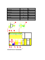
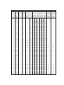
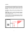
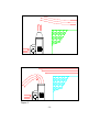
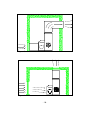
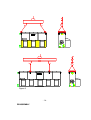
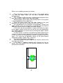
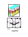
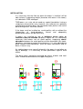
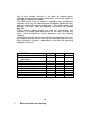
Cooling towers
series TMR
Service manual n. MS 12 00 TMR/E
INDEX
Important safety information
Pag.
2
Description of the machine
Pag.
5
Location
Pag.
7
Reference to models
Pag.
11
Shipment
Pag.
12
Lifting
Pag.
13
Reassembly
Pag.
15
Installation
Pag.
18
Start-up
Pag.
21
Operation
Pag.
23
Maintenance
Pag.
24
Setting out of service and dismantling
Pag.
31
Thank you very much for purchasing our equipment and be sure to
carefully read this manual before using the machine.
The series TMR cooling towers models 09 - 450 comply with the
European Community rules n. 89/392/CEE, 91/368/CEE, 93/44/CEE and
93/68/CEE.
- 1IMPORTANT SAFETY INFORMATION
Caution
Please read carefully this manual before using the machine. You will find
important information to safely use the machine.
Caution
The machine must be grounded. For protection during a lightning storm or
when the unit is left unattended and not used for a long time, turn off the
power supply to the unit. This will prevent the unit from damage due to
lightning or power line surges.
Caution
After connecting the motors, check for the correct rotation of fans.
Caution
Do not approach the unit when it is operating. Beware of corners and
edges.
Danger
Never introduce hands of foreign matters in the air inlet and outlet of the
machine.
Danger
Never open inspection doors when the machine is in operation.
Danger
The maintenance operations should never be accomplished when the unit
is in operation. Be sure that the machine has been disconnected before
entering the dangerous area or inside the machine.
Caution
The hot and humid ambient may favour the growth of micro-organism. For
specific recommendations consult a specialised water treatment supplier.
Caution
The recirculating water system may contain chemicals or biological
contaminants, which could be harmful if inhaled or ingested. Accordingly,
personnel who may be exposed directly to discharge airstream and
associated drift, mists generated during operation of the water distribution
system and/or compressed air should these be used to clean portions or
components of the recirculating water system, should wear respiratory
protection equipment approved for such use by local occupational health
and safety authorities.
Location
-2-
Each cooling tower should be located and positioned to prevent the
introduction of discharge air into the ventilation system of the building on
which the tower is located and of adjacent buildings.
Biological control
Blow down with or without chemical treatment for scale and corrosion
control is not adequate for control of biological contamination. The growth
of algae, slimes and other micro-organisms, if unchecked, will reduce
system efficiency and may contribute to the growth of potentially harmful
micro-organisms, in the recirculating water system. Accordingly, a biocide
treatment programme specifically designed to address biological control
should be initiated when the system is first filled with water and
administered on a regular basis thereafter in accordance with supplier's
instructions. For specific recommendations consult a competent water
treatment supplier.
-3Description
REFERENCE TABLE
Reference number
Material
Electric motor
Supports with bearings
Centrifugal fan
Float valve
Water filter
Make-up valve
Motor pulley
Transmission belt
Fan pulley
Secondary header
Drift eliminators
Wet deck fill
Gasket for header
Spraying nozzle
-4DESCRIPTION OF THE MACHINE
1
2
3
4
5
6
7
8
9
10
11
12
13
14
Metal
Metal
Metal
Polypropylene
Metal
Brass
Metal
Rubber
Metal
Polypropylene
Galvanised steel
PVC
Rubber
Rubber
The purpose of the series TMR cooling towers is to cool water by means
of the evaporative principle, that is rejecting heat by evaporating a small
percentage of the water itself.
The main components of the unit are essentially the water sump, inlet air
grills, evaporating fill, headers and nozzles for spraying water, drift
eliminators, centrifugal fans complete with transmission and electric
motor, casing.
The water is supplied to the tower by connecting it to a system with
circulating pumps, connected to the users. From the inlet header the water
is distributed through a spraying system to the upper part of the fill,
through it flows to the sump. At the same time the air blown by fans is
pushed in counter current through the fill upside; the air stream boosts the
evaporating process rejecting the heat from water. From the sump, the
water is exhausted in a closed circuit, going back to the users.
-5-
TECHNICAL DATA
Model
Air
Number
Number
Power
flow
of fans
of
each
motors
Ambient wet bulb temperature °C (2)
22°C
motor
26°c
inlet/outlet water °C
KW (1)
m3/s
24°c
35/29
45/30 35/30
45/30
35/30
KW
Power
Power
electric
electric
heater
heater
KW (3)
KW (4)
45/31
Pa 0- 50
Pa 100
KW
KW
KW
KW
09
2,19
1
1
0,75
1,5
101
171
90
149
70
KW
138
0,5
1
12
2,43
1
1
1,1
2,2
138
244
123
214
97
198
0,5
1
13
2,67
1
1
1,5
2,2
151
266
134
233
106
215
0,5
1
14
2,83
1
1
2,2
3
180
328
160
290
128
268
0,5
1
16
3,33
1
1
1,5
2,2
189
334
168
293
133
271
1
2
18
3,78
1
1
2,2
3
212
373
188
327
148
302
1
2
21
4
1
1
3
4
253
460
224
406
179
376
1
2
24
5
2
1
3
4
284
500
252
439
199
406
2
3
28
5,67
2
1
4
5,5
318
560
283
490
223
453
2
3
31
5,83
2
1
5,5
7,5
382
703
338
623
271
577
2
3
34
7,13
2
1
4
5,5
402
708
357
621
282
574
2
3
38
7,99
2
1
5,5
7,5
446
784
396
687
312
634
2
3
41
7,56
2
1
5,5
7,5
480
873
425
772
340
714
2
3
44
8,2
2
1
7,5
11
518
941
459
831
367
769
2
3
51
10,36
3
1
5,5
7,5
586
1033
521
906
411
837
3
4
56
11,33
3
1
7,5
11
635
1118
565
980
445
905
3
4
61
11
3
1
7,5
11
700
1275
620
1127
495
1043
3
4
66
11,67
3
1
11
15
739
1344
655
1187
523
1099
3
4
70
14,26
4
2
4+4
5,5+5,5
803
1416
715
1242
563
1147
3
4
76
15,98
4
2
5,5+5,5
7,5+7,5
891
1567
793
1373
624
1268
3
4
83
15,11
4
2
5,5+5,5
7,5+7,5
959
1746
850
1542
679
1428
3
4
88
16,42
4
2
7,5+7,5
11+11
1035
1882
918
1662
733
1538
3
4
94
19,33
5
2
5,5+7,5
7,5+11
1081
1902
962
1667
758
1540
2+2
3+3
103
18,56
5
2
5,5+7,5
7,5+11
1179
2147
1046
1898
835
1756
2+2
3+3
109
19,88
5
2
7,5+11
11+15
1256
2285
1114
2019
889
1868
2+2
3+3
122
22
6
2
7,5+7,5
11+11
1399
2549
1241
2252
991
2085
3+3
4+4
132
23,34
6
2
11+11
15+15
1478
2689
1311
2375
1046
2198
3+3
4+4
58
12,1
1
1
7,5
11
683
1206
608
1057
480
977
3
4
64
13,61
1
1
11
15
761
1339
677
1173
533
1084
3
4
74
13,99
1
1
15
18,5
884
1607
784
1420
626
1313
3
4
112
23,45
2
1
15
18,5
1328
2345
1182
2057
932
1901
4
5
125
24,95
2
1
18,5
22
1405
2478
1250
2173
986
2007
4
5
134
24,2
2
1
18,5
22
1545
2819
1370
2492
1094
2306
4
5
144
25,7
2
1
22
30
1634
2978
1449
2632
1157
2434
4
5
160
28,73
2
1
30
37
1811
3293
1607
2908
1282
2691
4
5
180
35,14
3
1
22
30
1991
3515
1771
3084
1397
2848
5
6
210
37,42
3
1
30
37
2384
4347
2114
3842
1688
3555
5
6
225
39,7
3
1
37
45
2518
4586
2233
4052
1783
3749
5
6
250
49,89
4
1
18,5+18,5
22+22
2811
4955
2500
4345
1971
4013
4+4
5+5
265
48,39
4
1
18,5+18,5
22+22
3089
5638
2740
4984
2189
4612
4+4
5+5
280
51,39
4
1
22+22
30+30
3267
5953
2897
5261
2314
4868
4+4
5+5
310
57,46
4
1
30+30
37+37
3623
6585
3214
5816
2564
5380
4+4
5+5
335
63,12
5
2
22+30
30+37
4017
7325
3563
6473
2846
5989
5+5
6+6
360
66,15
5
2
30+30
37+37
4196
7642
3722
6751
2971
6247
5+5
6+6
375
68,43
5
2
30+37
37+45
4330
7879
3841
6960
3065
6439
5+5
6+6
415
74,84
6
2
30+30
37+37
4767
8694
4228
7684
3377
7110
5+5
6+6
450
79,39
6
2
37+37
45+45
5036
9171
4467
8103
3566
7497
5+5
6+6
LOCATION
TMR cooling towers offer maximum flexibility of installation. Vertical
air discharge ensures that the operation of tower is not affected by
wind strength and direction for outdoor installation while the high
static pressure capacity of centrifugal fans makes it possible to install
TMR towers inside closed spaces with ducted air intake and/or
discharge.
It is necessary, however, to keep in mind some basic installation
rules which, if not observed, will impair correct operation of the
cooling tower.
No matter where the tower is installed, it will be necessary to leave
enough space around the tower for maintenance operation;
maximum accessibility is specially needed at the water connections
and at the inspection manhole.
In outdoor installations it is extremely important that the air intakes to
the fans are not obstructed; the tower should be placed so that walls
or other obstacles are at a distance from the intake grilles at least
equal to the grille eight (see Fig. 1).
Figure 1
-7-
A cooling tower should not be installed close to walls or obstacles
higher than the tower itself as in certain weather conditions this could
cause recirculation of the discharged air. If this is absolutely
necessary, a discharge air hood should be installed to increase the
discharge air velocity (see Fig. 2).
On the water connections side, or on the opposite side, it will be
necessary to leave a space equal to the length of the fan shaft so
that, if necessary, the shaft can be extracted for replacement of
bearings or fan wheels.
In installations with ducted air, sufficiently large inspection openings
on air intake and discharge ducts are necessary for easily reaching
the inside tower. The access to discharge ducts is for reaching spray
nozzles, after removing drift eliminator, and the one to intake ducts
for periodical checks of the fans (see Fig. 3-4).
Ducts should be so constructed as to give a minimum pressure drop,
with a low number of wide radius curves.
Horizontal stretches of ducts should be slightly sloping towards the
tower so that any water droplets, which might escape the drift
eliminator, will flow back to the tower.
If the air intake and discharge openings are to be ducted, care must
be taken to place the openings of the inlet and outlet ducts as far as
possible from each other to avoid any recirculation of moist air; a
good solution would be to place these openings on different walls.
In most cases it will be convenient to use only discharge ducts, air
intake being made through sufficiently large openings in the walls of
the room where the tower is installed, bearing in mind the previous
remarks about relative location of air inlet and outlet.
-8-
Figure 2
-9-
Figure 3
Figure 4
- 10 -
REFERENCE TO MODELS
In the following pages we give instructions related to different
typologies of the models of the series TMR.
To make the instructions easier, we will refer to the following model
groups:
A
= 09 12 13 14
B
= 16 18 21 28 28 31 34 38 41 44 51 56 61 66 70 76 83
88 94 103 109 122 132
C
= 58 64 74 112 125 134 144 160 180 210 225 250 265
280 310 335 360 375 415 450
- 11 -
SHIPMENT
TMR cooling towers - groups A and B models - are normally shipped
completely assembled to facilitate transportation and installation.
The models of group C are normally shipped divided horizontally in
two sections: the upper section includes the wet deck fill, the water
distribution system and the drift eliminator; the lower section includes
the water basin with the relative connections and the fan section.
The reassembly operations at the site shall be carried out at Buyer's
care and expense, following our instructions. Any accessory
equipment, such as silencers, marine ladders, railing, etc., shall be
always shipped disassembled and also their reassembly at the site
shall be carried out at Buyer's care and expense.
Shipment in one section of these towers must be especially
requested when placing order.
The towers divided in two sections are delivered along with a
sufficient special gasket and the bolts necessary for the reassembly.
- 12 LIFTING
Group A and B models
These models can not be divided and are equipped with 4 or 6 lifting
devices in the upper part of the unit, which allow to lift the all unit
(see Fig. 8 and 8/A).
Group C models
These models are equipped with two sets of lifting devices, one in
the upper part of the unit and another one inside the lower section.
The first one must be used to lift the all unit and the second one to
lift the lower section only, when this is separately shipped.
In both cases lifting should regard only small movements or the final
positioning, while for extended lifts, such as from ground to the top of
buildings, a suitable platform under the unit should be used (see
Fig. 5)
- 13 -
Figure 5
- 14 REASSEMBLY
When re-assembling, proceed as follows :
a)
b)
c)
d)
e)
f)
g)
Place the lower section of the unit on a flat surface, being
sure that the upper edge has not been damaged during
transportation.
Cut a suitable length of gasket, remove paper protection from
one side and press gasket onto base top flange.
Remove paper on the other side and drill holes in the gasket
in correspondence of the edge holes.
Place the bead sealer over the tape sealer in the area
between the holes and the inside of the unit (see Fig. 6).
Lift (according to the instructions of paragraph "Lifting") the
upper section of the unit and place it in position with the help of
metal pins into the holes of upper and lower flanges.
If the holes do not correspond, it means that either the lower
or the upper section of the unit are not flat; this may depend by
the support platform or by the way of hoisting the upper section
while assembling it.
In some cases, if it proves to be difficult to obtain perfectly flat
surfaces, it may be more convenient to re-drill some of the holes.
In this case be sure to previously remove the gasket from the
holes. It is necessary to perfectly centre all the holes before
lowering the upper section (Fig. 7 and 7/A).
Push bolts into position, and tighten.
Connect the plastic by-pass pipe to the manual valve on the
over-flow connection.
If the tower is supplied complete with silencers on the air
outlet, their reassembly must be effected following the above
mentioned instructions.
Figure 6
- 15 -
Figure 7
Figure 7/A
1) Guide pin
3) Flat gasket
2) Round gasket
Use 2 pins for each corner
- 16 -
Leakage sealing
During transportation and lifting the units can be submitted to
stresses that damage the sealing, which will result in water leakage
during operation.
Proceed as follows:
1)
Sealing must always be made from the inside part of joints.
2)
Seal only perfectly dryed surfaces.
3)
Remove previous sealants.
4)
Accurately degrease.
5)
Do not seal only the area where a leakage is taking place, but
largely exceed at the two sides.
6)
Apply the sealant in a sufficient quantity, but not excessive,
and as uniformly as possible.
7)
If necessary, slightly press the sealant to allow the
penetration between the surfaces.
8)
Do not use the unit for at least 24 hours. If the sump has
been sealed, it is advisable to protect the unit with plastic sheets
to avoid rain to get inside the unit.
Of course, use only suitable and good quality sealant.
Our Engineering Department will be glad to give you all the
suggestions you may need.
- 17 -
INSTALLATION
It is necessary that the floor on which the tower is installed will be
able to bear its operating weight (therefore with water in the tower),
as indicated in TMR catalogue.
TMR towers, as a rule, do not need any special foundation, having a
sturdy base frame which must, however, rest uniformly on a perfectly
levelled and horizontal base. For foundation bolts please refer to the
base drilling of our Technical Bulletin.
If the tower must be installed on metal profiles, with or without the
interposition of shock-absorbers, closed and adequately
dimensioned frames will be necessary.
If towers are installed on top of buildings where noise or
vibrations must be avoided (hospitals, hotels, etc.) it is absolutely
necessary that towers rest on metal profiles, employing shockabsorbers between the metal profiles and the foundation (for shockabsorbers size please contact manufacturers). It is also advisable to
place suitable shock-absorbing joints on water connections and air
ducts, if there is any.
As cooling towers are normally placed in the open air and often on
top of buildings, it is necessary to take precautions against wind
action.
The base frame should be anchored by means of bolts and steel
wires should be connected to the upper lifting ears.
Mod. A
Mod. B
- 18 -
Mod. C
As far as water connections are concerned, they depend mainly on
the particular installation and general rules cannot therefore apply.
We suggest however as follows:
Caution
-
-
While welding the flanges to water inlet and outlet joints,
care must be taken not to damage panels painting and sealing,
wet deck fill and nozzles. For this put wet rags at joints base.
The tower must be placed on the highest point of the water
circuit to avoid emptying the system when the pump is stopped. If
this is not possible, a check valve on the water outlet and an air
relief valve must be fitted.
Water circulating pumps must always be placed at a lower
level than the water one.
Water pipes must be properly sized and installed so that they
can normally expand.
In installations with two or more towers, care must be taken
to balance pressure drops in the various pipe branches and level
equalisation pipes must be connected to sumps.
Make-up pressure drop must be at maximum of 2 Bar.
Maximum operating pressure at water inlet connection
must be 0,8 Bar. Higher pressure values may seriously
damage internal distribution system of the machine.
Before to tighten the bolts and nuts of the flanged
connection, test the alignment and the flatness of the flanges.
It is also advisable to put shut-off valves before each tower to
enable separate maintenance of each tower; these valves are
also useful to even out differences in water flow to each tower.
As far as electrical connections are concerned, the following rules
apply:
a)
Fan motors up to 7,5 kW size are suitable for electrical
connection with direct start. For bigger size fan motors, soft
start systems as delta/star must be foreseen to prevent
excessive wear of the motors and of the transmission
system (if any). If two speed motors Dahlander type are
installed, motors must be started at low speed and switched
at high speed immediately after.
b)
If the motor of the cooling tower is remotely controlled by a
centralised control panel, it is advisable to install an isolating
switch in the immediate vicinity of the tower for the complete
safety of any maintenance operation.
c)
For winter operations it is advisable to install electric heaters
(with safety thermostat) in the tower sump in order to be sure that
all the water contained in the sump cannot freeze. Separate
electric wiring from the motor is necessary.
- 19 -
Sump heater must be controlled by an independent
thermostat (not included in our supply), follow-up linked to the
pump remote control switch and adequately protected against
short-circuiting. The bulb of the heater thermostat must be placed
in the water sump, as far as possible from the electric heaters
and near the sump bottom.
d)
Motors connection.
The electric motors installed on our evaporative cooling
equipment are normally insulated in class F with IP55 protection.
This high protection grade is the best guarantee of good and long
lasting operation in the humid ambient where normally the
motors are installed.
However it is important that while connecting the motor,
a particular care is given to the tight fastening of the cablepresser of the terminal box and to the fastening of the cover
of the same terminal box.
A bad fastening of the cablepresser and/or of the cover of the terminal box, would make
the motor subject to water infiltration, which would seriously
damage the bearings and the windings.
Even if the following are only general rules of good
technique, we wish to remind that after having connected the
motor, it is important to check that:
1) the connection is in accordance with the electric
characteristics with which the motor should operate and the
rotation is correct;
2) the cable-presser is perfectly tightened preventing any
water infiltration;
3) in case the connecting box has a number of holes for
wires, the ones that are not used should be tightly closed with
an hermetic plug;
4) while reassembling the cover of the terminal box, the
gasket should be correctly placed so as to ensure perfect
tightness.
Do not operate the unit if the above conditions are not
accomplished.
e)
All electrical connections must be effected according to
local regulations.
Caution
If the fan motor is controlled by an inverter (frequency variator),
please pay attention on its programming, to avoid the operation at
“critical” speeds.
START-UP
- 20 -
Each unit is tested at the factory before shipment, however the
following items should be checked prior to initial start-up:
-
if the float valve has been secured for shipment, free it;
-
check that the fans are free to rotate in the right direction;
-
if the drift eliminators are of the metal type, and they have
been removed for any reason during transportation and
installation, check that they are replaced with the air outlet edge
oriented opposite to the fan section (see Fig. 8):
Figure 8
- 21 -
The float valve on the make-up water connection is adjusted at the
factory, but it may be necessary to check for proper operation. The
float valve should be completely closed when the level in sump is
approximately 20 mm. below the overflow connection.
Conversely the water level should not be too low, as this should
enable air to be drawn into the pump, which would cause rapid wear
of the impeller. Moreover the insufficient water sprayed over the fill
would cause reduced efficiency and rapid scaling.
During the initial period of operation, foreign matter deposited in the
sump may reach the nozzles. It is therefore advisable to frequently
clean the nozzles during the initial period of operation as irregular or
reduced sprays may reduce the efficiency and increase scaling.
- 22 OPERATION
It is important that attention is given to quality of water to avoid build
up of scale, which reduces the heat exchange and consequently the
equipment efficiency.
As water is sprayed over the fill, a portion of it evaporates, thus
increasing the salts concentration in the remaining portion.
A purge connection is supplied with each unit, which allows to
increase the quantity of fresh water coming into the sump. This
dilutes the salts reducing the scaling effect of water. The purge pipe
is complete with a valve that should be regulated in accordance with
the water hardness.
As the quality of water is so important for the operation of an
evaporative cooling unit, we strongly recommend to contact a
specialised company asking for a suitable water treatment.
Reputable water treatment companies are perfectly aware of the
problems connected with evaporative cooling equipment and will
suggest the proper treatment.
Please note that the warranty for TMR units is valid only for
operation with water of very good quality.
- 23 MAINTENANCE
Due to their location, normally in the open air, cooling towers
although being relatively simple machineries, are usually subject to
very adverse operating conditions.
The TMR towers have an excellent protection from atmospheric
corrosion since they are fabricated from hot dipped galvanised steel
and then coated with baked-on epoxy paint. The electric motors and
bearings are water tight and specially constructed for outdoor
operation.
These features reduce greatly the need for maintenance, but
inevitably, to extend good performance of the tower through the
years, some maintenance service operations must be effected
regularly.
Listed below you will find the main maintenance operations that must
be regularly effected. Please note that the indicated frequency may
have substantial variations depending on the particular operating
conditions of the unit.
OPERATION
1) Sump and water filter flushing
2) Water level and valve
adjustment
3) Nozzles inspection
4) Fill check
5) Belt tensioning
6) Check bleed water
7) Check vibrations
8) Periodical fan operation
9) Bearings
10) Painting
11) Sump draining
Monthly
X
- 24 1)
Basin and water filter flushing
X
X
X
X
6 months
Annual
X
X
X
X
X
X
Empty the basin so as to eliminate every impurities. Clean
the water filter removing it if necessary.
2)
Valve and water level check
Check the ball valve to make sure that its operation is correct.
Tighten the bolts if necessary.
3)
Nozzles inspection
Inspect nozzles to be sure that all of them give a full and
continuous spray and are not obstructed or scaled by foreign
matters.
If necessary, remove the nozzles; this operation can be
accomplished without any tool as the nozzles are in rubber and
can be disassembled by pulling them gently with alternate
rotations. The reassembly operation can be made easier wetting
the connecting collar.
4)
Check fill surface
As scaling would build up because of improper water
treatment and/or irregular sprays, a frequent check of the fill may
save considerable damage to the unit. Uniform scaling would
mean that water treatment is not correct, while localised scaling
means that one or more nozzles are not properly spraying.
5)
Belt tensioning
Belt tensioning is needed the first time after about 12 hours of
operation, and monthly after that.
Electric motors are installed over platforms fastened by bolts
that must be loosened for tensioning belts.
The correct tension can be checked by depressing each belt
at the central point between the pulleys; the deflection should be
between 10 and 15 mm., depending on the distance between
pulleys and applying a moderate effort.
If the unit has a seasonal operation, at the end of the
season it is advisable to completely loosen the belts, which
will increase their life. If belt replacement is necessary,
purchase spares according with the type of belt stamped on the
nameplate of the unit.
Caution
Over-tensioning of belts may damage the motor and fan
bearings, while loose belts will slip, reducing equipment efficiency
and increasing belt wear.
6)
7)
Check bleed water
The bleed water pipe is complete with a valve that should be
regulated according with the conditions of water.
Check vibrations
- 25 -
Any fault with the fan, both centrifugal and axial, and/or
electric motor, will result in vibrations of the unit. If this occurs,
immediately stop the unit and check the reasons of vibrations.
This may save serious damage to the unit. Also the water
recirculating pump should be checked for vibrations.
8)
Periodical fan operation
If the unit is not operating for long periods of time, it is
necessary to foresee the periodical start-up of fan(s), in order to
prevent the excessive drying of bearings and gaskets.
9)
Bearings
Some of the bearings used for the shaft of centrifugal fans
are life lubricated and do not require additional lubrication under
normal conditions. If the bearings have a lubrication connection,
proceed as follows:
Initial start-up: normally no lubrication is required since the
bearings have been lubricated at the factory prior to shipment.
However, if the unit has been stored at the jobsite for more than
one year, bearings should be purged with new grease before
initial operation
Seasonal start-up: purge the bearings with new grease
prior to start-up.
Operation: lubricate bearings after every 2.000 hours of
operation or once every six months, whichever comes first.
Seasonal shut down: purge bearings with new grease prior to
any prolonged storage or downtime.
When lubricating, purge the old grease from the bearing by
gradually adding grease until a bread of new grease appears at
the seal on the underside of the bearing. We suggest to use
grease with the following characteristics:
- field of temperatures: from -20°C to + 110°C
- kinematics viscosity of the base oil: 190 mm2/s
- consistency (NLGI): 2
If the bearings are noisy, or vibrate or reach high
temperatures, they should be serviced or replaced.
10)
Painting
Thoroughly check all the painted parts of the unit to detect
possible areas where rust or corrosion has occurred. In this case,
clean the part with a metal brush and apply a rust treatment
product, such as Ferox of Arexons, Noverox, etc. . These
products will convert rust into inert salts (follow manufacturer
instructions).
- 26 -
After two or three days, remove product residue, if any, and
apply good quality enamels compatible with the existing one.
Normal protection units have a final coating with epoxy enamel,
while Decsaprot double protection units have a final poliuretanic
coating.
11)
Sump draining
Units with seasonal operation should be drained at the end of
the season to avoid freezing. If the unit is shut down during the
winter season, it is advisable to protect it with a water-tight
covering.
IDENTIFICATION DATA
TMR units have a nameplate indicating the model and the serial
number. For any information or spare parts requirements it is
necessary to refer to them.
- 27 -
FAILURE
CAUSE
The fans do not run.
No tension to the motor.
The motor is blocked.
The fan is blocked.
The transmission is without
belts.
The fans vibrate.
Unbalanced fan impeller.
Loosened keying.
The fans operate, but blow Backward rotation.
insufficient air.
Clanging fans.
The impeller strikes against the
casing.
Loosened keying.
The motor is noisy.
Damaged ball bearings. If the
noise is magnetic, faulty motor.
One phase is missing.
The motor is superheated.
Faulty motor.
Electric supply not correct.
Overload.
The belts slide at start-up or Insufficient tensioning.
during operation.
One or more nozzles do not Clogging.
spray.
One or more nozzles spray Partial scaling or clogging.
irregularly.
The evaporating fill is uniformly The circulating water is scaling.
scaled.
The evaporating fill is scaled in The water distribution is not
some areas.
uniform.
The
water
cooling
is Probable scaling of the fill, or
insufficient.
reduced air flow from the fans.
REMEDY
Fix the electric connections.
Clear the motor.
Clear the fan.
Balance the impeller.
Fix the keying on the shaft.
Fix the electric connection so
as to obtain the correct rotation.
Repair the casing or the
impeller.
Fix the keying.
Repair the motor.
Check the connection.
Repair the motor.
Check the electric supply.
Check the transmission.
Replace belt tensioning.
Remove the clogging.
Clean the nozzles.
Treat the water.
Check the nozzles to obtain a
uniform water distribution.
Totally or partially replace the
fill.
Check the fans.
Water carryover at the drift Excessive air flow.
Reduce the air flow.
eliminators.
Eliminators incorrectly placed.
Check the drift eliminators.
Water leakage along the Damage to sealing during Replace water tightness in
panels connections.
transportation
and/or accordance to the instructions
installation.
at page 19
Excessive water bleeding from Make-up ball valve too opened. Check the ball valve.
overflow.
The water level in the sump is Make-up ball valve too closed. Check the ball valve.
much lower than the overflow.
The water intake in the sump Too low water level.
Check the ball valve.
drags air (cavitation).
- 28 -
COMPONENTS LIST
Models TMR
Electricmotor
Complete fan 15/1
Complete fan 15/2
Centrifugal impeller 18/25
Centrifugal impeller 18/40
Fan pulley
Motor pulley
Impellers shaft 25
Impellers shaft 40/2
Impellers shaft 40/3
Supports with bearings 25
Supports with bearings 40
Transmission belts
Secondary header 85
Secondary header 115
Secondary header 175
Secondary header 235
Secondary header 295
Secondary header 355
Gasket for header
Nozzles type 20
Wet deck fill 900
Wet deck fill 1200
Drift eliminators 450
Drift eliminators 600
Water filter
Make-up ball valve
Gasket for inspection door
Inspection door
Door hand-wheel
U.M
n.
n.
n.
n.
n.
n.
n.
n.
n.
n.
n.
n.
n.
n.
n.
n.
n.
n.
n.
n.
n.
n.
n.
n.
n.
n.
n.
n.
n.
n.
09
1
1
1
1
1
3
3
9
3
2
1
1
1
1
4
12
1
1
1
1
1
3
3
9
6
2
1
1
1
1
4
13
1
1
1
1
1
3
3
9
6
2
1
1
1
1
4
14
1
1
1
1
1
3
3
9
9
2
1
1
1
1
4
16
1
1
1
1
1
2
2
3
3
12
4
3
2
1
1
1
1
4
18
1
1
1
1
1
2
2
3
3
12
4
3
2
1
1
1
1
4
21
1
1
1
1
1
2
2
3
3
12
8
3
2
1
1
1
1
4
24
1
1
1
1
2
3
3
18
12
3
1
1
1
1
4
28
1
1
1
1
2
3
3
18
12
3
1
1
1
1
4
31
1
1
1
1
2
3
3
18
18
3
1
1
1
1
4
34
1
2
1
1
1
2
3
3
3
24
8
6
4
1
1
1
1
4
38
1
2
1
1
1
2
3
3
3
24
8
6
4
1
1
1
1
4
41
1
2
1
1
1
2
3
3
3
24
16
6
4
1
1
1
1
4
44
1
2
1
1
1
2
3
3
3
24
16
6
4
1
1
1
1
4
51
1
3
1
1
1
2
3
3
3
36
12
9
6
1
1
1
1
4
56
1
3
1
1
1
2
3
3
3
36
12
9
6
1
1
1
1
4
61
1
3
1
1
1
2
3
3
3
36
24
9
6
1
1
1
1
4
66
1
3
1
1
1
2
1
3
3
36
24
9
6
1
1
1
1
4
70
2
4
2
2
2
4
2
6
6
48
16
12
8
1
1
2
2
8
76
2
4
2
2
2
4
2
6
6
48
16
12
8
1
1
2
2
8
83
2
4
2
2
2
4
2
6
6
48
32
12
8
1
1
2
2
8
88
2
4
2
2
2
4
2
6
6
48
32
12
8
1
1
2
2
8
94 103 109 122 132
2
2
2
2
2
5
5
5
6
6
2
2
2
2
2
2
2
2
2
2
1
1
1
1
1
1
2
2
4
4
4
4
4
4
4
4
6
6
6
6
6
6
6
6
6
6
6
6
60 60
60
72
72
20 40
40
48
48
15 15
15
18
18
10 10
10
12
12
1
1
1
1
1
1
1
1
1
1
2
2
2
2
2
2
2
2
2
2
8
8
8
8
8
COMPONENTS LIST
Models TMR
Electric motor
Centrifugal impeller 28/45
Centrifugal impeller 28/114
Fan pulley
Motor pulley
Impellers shaft P45/1
Impellers shaft P45/2
Impellers shaft C114
Supports with bearings 45
Transmission belts
Secondary header 175
Secondary header 265
Gasket for header
Nozzles type 20
Wet deck fill 900
Wet deck fill 1200
Drift eliminators 1045
Water filter
Make-up ball valve
Gasket for inspection door
Inspection door
Door hand wheel
U.M
n.
n.
n.
n.
n.
n.
n.
n.
n.
n.
n.
n.
n.
n.
n.
n.
n.
n.
n.
n.
n.
n.
5
1
1
1
1
1
2
3
5
5
4
2
6
6
1
1
1
1
4
6 74 112 125
1 1
1
1
1 1
2
2
- 1 1
1
1
1 1
1
1
1 1
- 1
1
- 2 2
2
2
3 3
4
4
5 5 10
10
- 5 5 10
10
4 45 90
90
2 34 12
12
6 6 33
33
6 6 12
12
1 1
1
1
1 1
1
1
1 1
1
1
1 1
1
1
4 4
4
4
134
1
2
1
1
1
2
4
10
10
90
12
54
12
1
1
1
1
4
144
1
2
1
1
1
2
3
10
10
90
12
54
12
1
1
1
1
4
160
1
2
1
1
1
2
4
10
10
90
12
54
12
1
1
1
1
4
180
1
3
1
1
1
2
3
10
10
140
32
39
18
1
1
1
1
4
210
1
3
1
1
1
2
3
10
10
140
44
60
18
1
1
1
1
4
225
1
3
1
1
1
2
3
10
10
140
44
60
18
1
1
1
1
4
250 265
2
2
4
4
2
2
2
2
2
2
4
4
4
8
20 20
20 20
185 185
24 24
66 108
24 24
1
1
1
1
2
2
2
2
8
8
280 310 335
2
2
2
4
4
2
3
2
2
2
2
2
2
2
2
1
1
4
4
4
6
6
8
20
20
10
10
20
20
20
185 185 230
24
24
58
108 108 114
24
24
30
2
2
2
1
1
1
2
2
2
2
2
2
8
8
8
360
2
2
3
2
2
1
1
4
8
10
10
20
230
58
114
30
2
1
2
2
8
375 415
2
2
2
3
6
2
2
2
2
1
1
2
4
4
8
8
10
10
20
20
20
230 280
58
36
114 162
30
36
2
2
1
1
2
2
2
2
8
8
450
2
6
2
2
2
4
8
20
20
280
36
162
36
2
1
2
2
8
SETTING OUT OF SERVICE AND DISMANTLING
In case the unit, for wear, irreparable damage or other reasons, must
be set out of service and dismantled, it will be advisable to separate
the non-metal parts like rubber, plastic, etc. before sending it to
scrapping.
The non-metal parts are mainly the heat exchange fill in PVC, the
water distribution headers, water nozzles, transmission belts and the
float valve of the water make-up valve.
Electric motors of fans have the winding in copper wire, for which it is
advisable a separate scrapping.
- 31 -