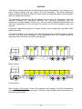
1
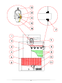
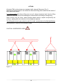
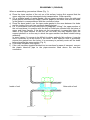
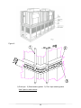
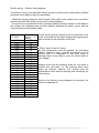
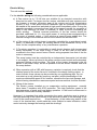
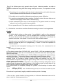
TMA series
Cooling Towers
Service Manual no. MS 02 11 TMA/E
Rev. 3
INDEX
Introduction and general safety information
Page 4
Standards and important safety information
Page 5
Description of the machine/unit
Page 9
Location
Page 14
Shipment
Page 17
Lifting
Page 18
Reassembly
Page 19
Installation
Page 21
Electric wiring
Page 24
Start-up
Page 26
Operation / Running
Page 30
Maintenance
Page 32
Trouble-shooting guide
Page 36
Spare parts
Page 38
Decommissioning, dismantling and disposal
Page 42
Appendix I : Characteristics
Appendix II : User’s or operator’s notes
Appendix III : Electric wiring diagrams for the connection of the fan motors
Appendix IV : Identification data
1
2
Thank you very much for purchasing our equipment and be sure to carefully read this
manual before using the machine.
The series TMA cooling towers models 08-55 ÷ 39-866 comply with the European
Community directive no. 98/37/CEE.
3
INTRODUCTION AND GENERAL SAFETY INFORMATION
Care / Caution
The objective of this manual is to make available to the purchasers, to the operators
and to the maintenance personnel all the indications necessary for the installation, the
start-up, the running, the maintenance and the resolution of eventual faults of TMA
series cooling towers. Please read carefully this manual before using the unit. You will
find information important for the safe usage of TMA series cooling towers.
The residual risks and the related precautions are indicated in each chapter of
instructions.
To minimize the risks, it is essential that these instructions are carried out by technically
competent personnel to ensure safe and reliable installation and running of the
equipment. Moreover it is important that the contractor, the maintenance technician and
the user assure themselves that all the personnel assigned to, or responsible for, the
installation, the operation and/or the maintenance of the TMA cooling tower have
received training based also on this manual, with particular reference to chapters 2 and
3 and to those relevant to their job and/or to their work on the equipment and that this
occurs prior to the start-up of the cooling tower. The instructions in the manual must be
scrupulously respected and followed. Many accidents are due to an incorrect usage of
the equipment.
In the event of any difficulty in interpreting these instructions, it is essential to consult
Decsa for help and advice.
The plant must NOT be put into operation prior to having
clarified all possible doubts.
4
STANDARDS AND IMPORTANT SAFETY INFORMATION
The reference standards for the design and the construction of these units and for the
related instructions for the user are as follows :EN 418
EN 292/1
EN 292/2
EN 294
EN 953 for the design of the protective screens
EN 60204/1
EN 60335/1
EN 60439/1
ISO 7000 for symbols of danger, forbidden actions, usage + info
ISO 3874 for lifting
EN 563
For the installation, the adjustment,, the maintenance and the eventual demolition of the
unit, safety at work procedures in accordance with the following directives must be
respected :
89/391/CEE
89/394/CEE
89/654/CEE
89/655/CEE
89/686/CEE
89/695/CEE and eventual subsequent modifications
In general terms it should be remembered that the personnel assigned to the works
must employ the usual personal protection equipment and overalls, always avoiding the
use of loose clothing, jewellery and covering long hair.
PERMITTED USES : the cooling tower is foreseen exclusively for the cooling of water
as per the description of the unit and in accordance with the selection data of the
quotation and of the related order. Respect at all times the maximum temperature for
the heat exchange surface = 55°C . Other temperatures and/or applications are not
admissible if not previously agreed with the manufacturer in the design and quotation
phase. Decsa Srl will not accept any responsibility for injury to persons and/or damage
to other objects due to a non-respect of these limitations.
The unit must be earthed. For protection during a thunder storm or when the unit is left
unattended and unused for a long time, turn off the power supply to the unit. This will
prevent damage to the unit due to lightning or power line surges. Provided that the
cooling tower is connected-up with standard-compliant components, installed in
accordance with the standards, there will be no further electrical risk due to the cooling
tower.. In any case a differential line-breaker must be provided for all the electrical
equipment of the cooling tower.
After connecting the motors, check for the correct direction of rotation of fans.
Shut-off Device (by others) – to be provided and installed near the cooling tower for the
operations of adjustment, maintenance and replacement of components. According to
the EN 60204-1 standard, an emergency stop must be such that the rearming of the
shut-off device, with which the tower is equipped, does not permit a new start.
Consequently the eventual use of the said device for emergency stops will require the
presence of another switch, to be connected, in series with the switch of the shut-off
5
device itself, to the central control panel in such a way that the electric current is shut-off
also at the central panel when the shut-off device is activated.
RESIDUAL RISKS AND RELATED PRECAUTIONS
Do not approach the unit when it is operating. Beware of corners and edges.
Characteristics of the mechanical protection devices
The protection devices (screens) are robust, do not introduce further risks, are external
to the danger zones and do not obstruct the field of vision. The installation work does
not require the removal of these protective screens but the maintenance operations
could require it. Such removal does however necessitate the use of suitable tools (and
in any case the cooling tower should be fitted with a shut-off device, by others, to be
employed at the time of such operations).
The protective mesh screens on the air discharge are well anchored in position and held
by nuts and bolts, hence requiring tools (2 spanners) for their removal.
CAUTION : owing to the “wedge-in” system of the angled screens at the top of the
cooling tower, these remain in place even without their fixings (whereas the flat screens
do not remain in place by themselves). The presence of the related nuts and bolts
must be ensured after every operation or work intervention.
Further Mechanical Protection Devices
In the case of installation of the cooling tower in an area accessible to exposed persons,
the end-user must provide a standards-compliant enclosure since the area around the
cooling tower is to be considered a potential danger zone and, without an enclosure,
third-party outsiders could possibly remove a protective screen equipping the tower,
creating in consequence greater risks for other exposed persons (and/or domestic
animals)
Access to the upper area of the cooling tower
Employ a suitable standards-compliant ladder. In the case of more prolonged and
complex intervention on the motor-fan sets the use of a state-of-the-art scaffolding,
compliant to current safety standards, is recommended. The tower is equipped with
access doors to the droplet eliminators inside. After installation of the unit, one could
eventually fit (by others) the access doors with safety micro-switches. The dangers to
be avoided by the operators and other exposed persons are twofold: access to the fans,
possibly running and close contact with the flow of humid air, entraining droplets of
chemically treated water. The disadvantage of employing a safety device would be the
possible shut-down of the fans, with the consequent reduction in cooling capacity at
some moment when the cooling requirement is highest, in the case of mistaken opening
or non-programmed entry into the unit.
The hot and humid ambient may favour the growth of micro-organisms. For specific
recommendations consult a specialised water treatment supplier.
Protection against Biological Risks
The recirculating water system of a cooling tower may contain chemicals or biological
contaminants, which could be harmful if inhaled or ingested. Accordingly, personnel
who may be exposed directly to discharge airstream and associated drift, mists
generated during operation of the water distribution system and/or compressed air,
should this be used to clean portions or components of the recirculating water system,
should wear respiratory protection equipment approved for such use by local
occupational health and safety authorities.
6
Prevention of Biological Risks
Location Each cooling tower should be located and positioned to prevent the
introduction of discharge air into the ventilation system of the building on which the
tower is located and of adjacent buildings.
Biological control
Blow down with or without chemical treatment for scale and corrosion control is not
adequate for control of biological contamination. The growth of algae, slimes and other
micro-organisms, if unchecked, will reduce system efficiency and may contribute to the
growth of potentially harmful micro-organisms, in the recirculating water system.
Accordingly, a biocide treatment programme specifically designed to address biological
control should be initiated when the system is first filled with water and administered on
a regular basis thereafter in accordance with supplier's instructions. For specific
recommendations consult a competent water treatment supplier.
Note : It is recommended that operators and maintenance technicians refer also to
the Eurovent guide 9-5 (2° Ed. 2002) for the prevention of biological contamination
in evaporative cooling systems.
Dangers of mechanical origin
Never place hands or introduce foreign bodies in the air inlet and outlet of the unit.
Never open inspection doors when the unit is in operation (rotating machinery).
Maintenance operations should never be performed when the unit is in operation. Be
sure that the unit has been disconnected before entering the dangerous area or inside
the unit itself (rotating machinery inside).
.
Warning signs and indications about the residual risks present on the unit
CAUTION DANGEROUS EQUIPMENT:
read carefully this manual of instructions for use before
performing any operation of the unit.
CAUTION DANGER OF ELECTROCUTION :
do not manipulate electrically live items without having
previously disconnected the unit from the mains electricity
supply . Work on the electrical installation should only be
performed by very expert personnel, qualified in such
matters.
IT IS FORBIDDEN TO CLEAN, LUBRICATE or WORK ON
THE UNIT DURING ITS OPERATION :
It is forbidden to perform lubrication or cleaning works with
the unit in operation.
CAUTION: IT IS FORMALLY FORBIDDEN TO WORK ON
OR PERFORM WORKS OF ANY KIND NEAR TO THE
COOLING TOWER WHEN IT IS IN OPERATION.
7
FURTHER APPLICATION NOTES:
Cut-out devices linked to vibration (“vibro-switch” type) can be supplied on request for
critical situations (and would be for connection to the electrical control panel).
Alarm devices are NOT envisaged.
Information systems are NOT envisaged. The health and safety of exposed persons
could be put at risk by the malfunction of a unit that operates unsupervised only if, for
example, a cooling tower were to no longer cool a process which as a consequence
would become dangerous ( of the “thermal runaway” type ). Such a usage of the
cooling tower represents a danger linked to the plant itself and it is advisable to fit such
a user circuit with an audible or visible alarm device.
Motors and other electrical accessories for use in explosive atmospheres are available
on request. The standard electrical equipment is not explosion-proof.
FURTHER RESIDUAL RISKS:
Only for the larger and higher capacity TMA cooling powers, close to the motor-fan set :
Danger for the sense of hearing (take into account the sound pressure levels in the
design phase).
Only for the eventual scale-removal washing (with inhibited sulphamic acid) from the
heat exchange surface : possible danger due to the presence of corrosive fluids.
8
DESCRIPTION OF THE UNIT
TMA series cooling towers are machines of relatively simple design and operation: their
purpose is the cooling of water by means of the evaporative principle, that is rejecting
heat by evaporating a small percentage of the water itself.
The main components of the unit are essentially the water sump, inlet air grills,
evaporative wet deck fill fill, headers and nozzles for spraying water, drift eliminators,
axial fans complete with electric motors, casing.
The water is supplied to the tower by connecting it to a system with circulating pumps,
connected to the users. From the inlet header the water is distributed through a
spraying system to the upper part of the fill, through which it flows to the sump. At the
same time the air induced by fans is drawn upwards in counter current through the fill;
the air stream boosts the evaporating process rejecting the heat from water. From the
sump, the water is pumped, in a closed circuit, back to the user items being cooled.
The quantity of water evaporating varies as a function of the actual heat load on the
cooling tower at a given moment. Moreover it diminishes when the outside ambient
temperature decreases in the winter / low season since the effect of the sensible heat
exchange between the hot water to be cooled and the induced draught of air becomes
significant. The temperature of the water leaving the cooling tower is determined by
the design wet bulb temperature of the intake air : its value will in any case ( for a
reasonable selection ) be 3 – 4°C above the summer design wet bulb temperature.
TMA units are selected and quoted on a “job-to-job” basis for each project and are
normally foreseen for usage at the summer operating conditions shown in the
quotation.
It should be remembered that, when designing a cooling plant to include a TMA
evaporative cooling tower, it is necessary to consider several important aspects:
* Layout / Location
* Piping
* Antifreeze protection
* Water treatment
* Sound level limitations - with respect also to capacity control [ i.e. the type and/or the
control of the fan motors ]
The characteristics of the TMA models are listed in an appropriate table in appendix I
9
REFERENCE TABLE . DIRECT-DRIVE MODELS
Description
Reference no.
Material
Axial fan
1
Metal
Drift eliminator
2
PVC
Inspection door
3
Fibreglass
Side panel
4
Metal
Air inlet grilles
5
Polypropylene
Float ball
6
PVC
Electric motor
7
Metal
Secondary header for nozzles
8
Polypropylene
Wet deck (heat exchange) fill
9
PVC
Make-up valve
10
Brass
Water filter
11
Stainless steel
Fixing collar with pommel
12
Stainless steel
Tapered connection
13
PVC
Nozzle gasket
14
Rubber
Nozzle impeller
15
Moplen
Main body of nozzle
16
Moplen
Header gasket
17
EPDM (rubber)
10
11
REFERENCE TABLE - MODELS WITH MECHANICAL DRIVE SYSTEM
Description
Reference no.
Material
Axial fan
1
Steel + Aluminium
Drift eliminator
2
PVC
Inspection door
3
Fibreglass
Side panel
4
Galvanised steel
Air inlet grilles
5
Polypropylene
Float ball
6
PVC
Electric motor
7
Metal
Secondary header for nozzles
8
Polypropylene
Wet deck (heat exchange) fill
9
PVC
Make-up valve
10
Brass
Water filter
11
Stainless steel
Fixing collar with pommel
12
Stainless steel
Tapered connection
13
PVC
Nozzle gasket
14
Rubber
Nozzle impeller
15
Polypropylene
Main body of nozzle
16
moplen
Header gasket
17
EPDM (rubber)
Orthogonal gearbox
18
Cast iron + Steel
Drive transmission shaft
19
Steel
Lamellar joint
20
Stainless steel
12
13
LOCATION
Consult the related detailed guidelines of Decsa Srl both for the general aspects of
correct location of cooling towers and for the aspects specific to the installation to be
built.
TMA cooling towers offer maximum flexibility of outside installation. The vertical air
discharge ensures that the operation of the tower is not affected by wind strength and
direction.
It is necessary, however, to keep in mind some basic installation rules which, if not
observed, will impair correct operation of the cooling tower.
It is important that the air intakes to the cooling tower are not obstructed. Exact values
for the distances to be respected between tower and full walls are based upon the
velocity of the drawn air in the corridors created between them: this matter is covered in
detail in our layout guidelines.
Avoid air recirculation. In choosing the site of installation it is important that this aspect
is duly taken account of.
The warm, saturated air discharged from the cooling tower must be able to freely
disperse into the surrounding atmosphere; if a part of this saturated air is recirculated
back through the tower, the latter’s efficiency is compromised.
A cooling tower should thus not be installed close to walls or obstacles higher than the
tower itself which impede the easy dispersion of the discharged air to the surroundings.
Do not obstruct the air intake and discharge.
The air is the means by which the heat of the water is rejected to the surrounding
atmosphere. Good air circulation is thus fundamental to obtain the best results from
your cooling tower.
Ensure therefore that all the air intakes are free of obstacles and that the air can be
freely discharged in the correct manner.
Protective roofing is not admissible.
14
Multiple TMA cooling towers in a row
When installing several TMA cooling towers in a row, or as a group, one must ensure
that the operation of each single tower does not affect the operation of the others; for
the minimum layout distances to be respected please contact our engineering dept..
When installing three or more towers, particular care should be taken to avoid the
danger of air recirculation, above all for the towers in the central position.
TMA Cooling towers without basin/sump
When installing one or more cooling tower (supplied less basin/sump) above a concrete
sump, apart from the aspects previously described, verify that the cross-section
available for airflow is sufficiently large.
Free area to be respected
Taking account of all the aspects previously cited, it will be necessary to leave enough
space around the tower for maintenance operations; in particular maximum accessibility
is needed at the side where the main water connections are located, at the inspection
manholes/doors, for access to and maintenance of the inside of the unit and at the side
where the pan connections are located.
It can be observed that the rules and suggestions presented here are of a general
nature. Given the great variety of practical cases it is difficult to provide definite
indications but our layout guidelines do provide more specific indications for various
types of tower location; our engineering dept. can be contacted to obtain any further
information necessary. .
The dimension “B” is to be found in the TMA series technical catalogue
15
16
SHIPPING
TMA series cooling towers are normally shipped divided horizontally in two sections: the
upper section includes the fan section, the drift eliminators, the water distribution
system and the wet deck fill whilst the lower section includes the water collecting basin
(with the related connections).
The reassembly operations at the site shall be carried out at the Purchaser's care and
expense, following our instructions provided. Any accessory equipment, such as
marine-style access ladders, railings, etc., shall be always shipped disassembled and
also their reassembly at the site shall be carried out at the Purchaser's care and
expense.
Completely assembled shipment of these towers must be especially requested when
placing the order.
The towers divided in two sections are delivered along with a sufficient special gasket
and the (nuts and) bolts necessary for the reassembly: this kit is placed inside the
inspection door and there is a label to indicate this.
Upper section
Lower section
Upon receipt of the goods, ensure the presence and integrity of all the components,
communicating any apparent anomaly to Decsa Srl with suitable notes made directly on
the delivery documents.
17
LIFTING
All series TMA cooling towers are equipped with external lifting ears (Fig. 3).
Whereas the pans/sumps of the towers are fitted with lifting ears located on the inside of
their uppermost flange.
It is indispensable that these lifting ears are all, always tensioned and that the lifting
cables act vertically and avoid breakages or deformations and danger during lifting.
When moving only the lower, water-collecting basin section, respect scrupulously the
scheme, paying particular attention to the slings and spacers.
The lifting ears must in any case be used for small movements or for final positioning,
whereas for extended lifts (such as from ground to the top of a building,) a suitable
robust platform under the unit should be used .
CAUTION: SUSPENDED LOADS
Figure 3
18
REASSEMBLY (RIGGING)
When re-assembling, proceed as follows (Fig. 1):
a) Place the lower section of the unit on a flat surface, having first ensured that the
upper edge has not been damaged during transportation. Clean carefully.
b) Cut a suitable length of sealer-gasket, remove paper protection from one side and
press gasket onto base top flange. Remove paper on the other side and drill holes
in the gasket in correspondence with the connection holes.
c) Place the bead sealer over the tape sealer-gasket in the area between the holes
and the inside of the unit (see sectional drawing below).
d) Lift, in accordance with the instructions of paragraph "Lifting", the upper section of
the unit and place it in position with the help of metal pins inserted into the holes of
upper and lower flanges. If the holes do not correspond, it means that either the
lower or the upper section of the unit are not level; this may depend upon the
support platform or on the way in which the upper section has been hoisted during
assembly.
In some cases, if it proves to be difficult to obtain perfectly flat surfaces, it may be
more convenient to re-drill some of the holes. In this case be sure to previously
remove the gasket from the holes. It is necessary to perfectly centre all the holes
before lowering the upper section (Fig. 2)
e) Push bolts into place, and tighten.
f) If the unit has been supplied divided into two sections for ease of transport, connect
the plastic bleed-off pipe to the pipe-connector fitted above the over-flow
connection.
Inside of unit
Outer side of unit
19
Figure 2
1) Guide pin 2) Bead sealer-gasket 3) Flat / tape sealer-gasket
Use 2 pins in each corner
20
INSTALLATION
Over and above the indications provided in the chapter on “Location” it is necessary to
ensure beforehand that the supporting surface on which the tower is installed will be
able to bear its operating weight (therefore with water in the tower), as indicated in the
TMA catalogue. TMA series cooling towers do not normally require additional support
structures.
TMA cooling towers must rest uniformly on a perfectly level and horizontal base. If the
cooling tower must for some reason be installed on metal profiles, with or without the
interposition of vibration isolators, apart from the lateral beams, one or two central
support beams must also be provided.
As cooling towers are normally placed in the open air and often on top of buildings, it is
necessary to take precautions against effects from wind action: the base frame should
be anchored by means of bolts and steel wires should be connected to the upper lifting
ears.
Generally speaking, the indications given above must also be taken into account when
installing a TMA tower less sump/basin (above a concrete sump).
As far as water connections are concerned, given their dependence mainly on the
particular installation, general rules cannot apply. We suggest do however suggest the
following:
Caution
While welding the flanges to water inlet and outlet connections, care must be
taken not to damage surface finish of the paintwork and panel sealing, wet deck fill and
nozzles. For this purpose wet rags should be inserted at the base of the connections.
- The piping must be supported independently of the cooling tower and
not impose any load upon it.
The tower must be placed on the highest point of the water circuit to avoid
emptying the system when the pump is stopped. If this is not possible, a check valve on
the water outlet and an air relief valve must be fitted.
Water circulating pumps must always be placed at a lower level than that of the
water level in the tower.
Water pipes must be properly sized and installed so that normal expansion and
contraction is possible.
In installations with two or more towers, care must be taken to balance
pressure drops in the various pipe branches and level equalisation pipes must be
connected to sumps.
Make-up pressure head must be at maximum of 2 bar.
Maximum operating pressure at water inlet connection must be 0,8 bar.
Higher pressure values may seriously damage the water distribution system
inside the unit.
Before tightening the bolts and nuts of the flanged connection, check the
alignment of the flanges themselves and that they are in parallel planes.
- It is also advisable to install shut-off valves on each tower to enable separate
maintenance of each; these valves are also useful to even out differences in water
flow to each tower. Whereas the possibility of this shut-off is convenient,
the possibility of adjustment to balance the flows is very important.
21
Sealing of Leakages
During transportation and lifting the units can be submitted to stresses that damage the
sealing, which will result in water leakage during operation.
To eliminate these leakages it is essential to proceed as follows:
1) Sealing must always be made from the inner side of joints.
2) Seal only perfectly dried surfaces.
3) Remove previous sealants.
4) Accurately degrease.
5) Do not seal only the area where a leakage is taking place, but rather seal an excess
length at both ends.
6) Apply the sealant (with the extruder for that purpose) in a sufficient, but not
excessive quantity, and as uniformly as possible.
7) If necessary, slightly press the sealant to allow the penetration between the
surfaces.
8) Do not use the unit for at least 24 hours. If the sump has been sealed, it is advisable
to protect the unit with plastic sheets to avoid rain reaching the recently sealed area.
Naturally only suitable and good quality sealant must be used (single-component,
non-acetic silicon).
Our Engineering Department will be glad to provide you with any further advice you may
need.
22
Electric wiring – Electric wiring diagram
The electric wiring is an operation which should be performed by particularly qualified
personnel (even better if they are specialists)
- Check the integrity along the whole length of the cable to be used for the connection
and then proceed with wiring-up as per the wiring diagrams.
- The minimum cross-section of the connecting cables should be chosen on the basis of
the voltage, the installed power and the distance between the power source and the
user point as per the following table:
Motor power Cable crosssection
“S”
“P” [kW]
2
[mm ]
0,09
1,5
0,12
1,5
0,18
1,5
0,25
1,5
0,37
1,5
0,55
1,5
0,75
1,5
0,9
1,5
1,1
1,5
1,5
1,5
1,8
1,5
2,2
1,5
3
2,5
4
2,5
5,5
4
7,5
4
9
6
11
6
15
10
18,5
10
22
16
30
25
37
25
45
35
55
35
Check that the primary electricity line to which the unit is
to be connected has the same voltage and frequency as
that foreseen for the operation of the unit .
- Effect “state of the art” wiring.
All live components must be earthed. All connecting
cables – phases + earth – must be connected in such a
manner that it is impossible to tear them away or
damage them in any fashion (even for those items at
low voltage).
Always check that the earthing wires are not those to
neutral and vice-versa; i.e. the earthing wires must
make an effective earthing. The neutral must be
employed as such and the earthing wire exclusively for
that purpose.
Refer to the electric wiring diagrams for wiring-up the
motors in appendix III
23
Electric Wiring
The unit must be earthed
For the electric wiring the following considerations are applicable:
a) A Fan motors up to 7,5 kW size are suitable for an electrical connection with
direct-on-line start. For larger size fan motors, star/delta soft start systems must
be foreseen to prevent excessive wear of the motors and of the transmission
system (if any). If two speed motors Dahlander type are installed, motors must
be started at low speed and switched at high speed immediately after. During the
opposite procedure (commuting from high to low speed) provide for a system of
delay in the switching (at least 15 seconds) in order to avoid overloading the
motor winding.
Thermal overload protection of the fan motors should be
provided, calibrated for 1,1 x the motor power. A cooling tower equipped with a
fan motor of nominal output > 3 kW requires a second power supply line. The
nominal voltage of the electrical control circuit should not exceed 250V
b) s If the motor of the cooling tower is remotely controlled by a centralised control
panel, it is advisable to install an isolating switch in the immediate vicinity of the
tower for the complete safety of any maintenance operation.
c) C For winter operation it is advisable to install electric heaters (with incorporated
safety thermostat) in the tower sump in order to be sure that all the water
contained in the sump cannot freeze. Electric wiring separate from that of the fan
motor is necessary.
The sump heater must be controlled by an independent thermostat (not included
in our supply), follow-up linked to the pump remote control switch and adequately
protected against short-circuiting. The bulb of the heater thermostat must be
placed in the water sump, as far as possible from the electric heaters and near
the sump bottom.
d) When operation with a VSD with frequency variation is required, check that the
rotation speed of the motor-fan set is included in the design limiting values; in
case of doubt, these values can be provided by our engineering dept. Do not
ever start-up a unit (piloted by frequency variation) without knowledge of the
maximum admissible speed of fan rotation, otherwise the fans risk damage, and
without having checked the resonance speed and ensured that it will be avoided.
e) Wiring of the motors.
The electric motors installed on our evaporative cooling equipment normally
have class F insulation with IP55 protection. This high protection grade is the
best guarantee of good and long lasting operation in the humid environment in
which the motors are normally installed.
However it is important that while connecting the motor, particular care is given to
the tight fastening of the cable-entries of the terminal box and to the fastening of the
cover of the same terminal box.
A bad fastening of the cable-entry and/or of the
cover of the terminal box, would make the motor subject to water infiltration, which
would seriously damage the bearings and the windings.
24
Even if the following are only general rules of good technical practice, we wish to
remind
whoever installs the wiring that after having wired-up the motor, it is important to check
that:
1) the wiring is in accordance with the electric characteristics with which the motor
should operate and that the direction of rotation is correct;
2) the cable-entry is perfectly tightened preventing any water infiltration;
3) in case the connecting box has a number of holes for wires, the ones that are not
used should be tightly closed with an hermetic plug;
4) while reassembling the cover of the terminal box, the gasket should be correctly
placed so as to ensure perfect impermeability.
Do not operate the unit if the above conditions are not attained.
f)
All electrical connections must be effected according to current local regulations.
Caution
-
To effect electric wiring or other works it is prohibited to walk on the uppermost
surface of the cooling tower if it is not equipped with a walkway for that purpose.
To access the motors it will therefore be necessary to protect the zone where the
operator must pass with planks of wood or with other suitable means.
-
If the fan motor is controlled by an inverter (VSD with frequency variation), particular
attention should be paid to its programming, in order to avoid the operation at
“critical” speeds.
In order to avoid unexpected wearing out of the motor, it is recommend to not
exceed
the ceiling of 5 starts per hour..
g) The electric motors from 0,55 kW (L80) up to 22 kW (L180) are equipped with prelubricated bearings, which do not necessitate any lubrication and their operating life is
about 30.000 hours.
The motors from 30 kW (L200)m up to 45 kW (L250) are equipped with open bearings,
requiring lubrication . The bearings have an automatic grease discharge device.
The bearing chambers are to be pre-filled with grease to not more than half of their
capacity, since an excessive grease quantity makes the bearings run hot. It is
recommended to refill the bearings with grease every 1500 hours of motor operation, or
at least once every 6 months.
Lithium grease must be used for lubrication. The refilling of bearings with grease can be
made through the greasing nipple fastened in the bearing cover on both sides of the
motor. Before refilling the grease nipple must be cleaned.
It is recommended to completely change the grease in the bearings of motors with
speed:
1500 rpm (50 Hz)
up to
1800 rpm (60 Hz) after 10.000 working hours, but not later than after 2 years
Precautions for particularly lengthy installation and/or periods of storage
- If the unit is to remain inactive for long periods, or if site work becomes drawn out it is
wise to take the following precautions:
25
- the electric motors are designed and built to work in a humid air flow, however these
components are not perfectly water-tight; some manufactures in fact adopt condensate
drain holes, to permit the motor to expel (whilst running) the residual humidity l inside
the stator.
- Such refinements are designed to serve their purpose during the normal usage of the
motor and, in the particular case of long shut-downs, these holes can be the cause of
water infiltration and give rise to blockage of the rotating parts.
- The bearings at the two ends of the rotor are of a self-lubricating type and, as
described for the condensate drain holes, serve their purpose correctly during normal
motor usage; a long period of inactivity can give rise to wear of these elements for lack
of lubrication.
To avoid running into the above-listed problems a regular, periodic operation of the
motors must be programmed,: if that were not possible it is recommend to remove the
electric motor and any gearbox and to store it in a dry area not subject to sudden
variations in temperature.
START-UP
Fan control (by others) must be such that the fan motor is activated only after start-up of
the cooling water pump.
Before initial start-up verify the alignment of all the section of the unit and the correct
emplacement of the various components. Check that all the air discharge screens are
in place and that the related fixings are tightened. Ensure that all the installation work,
adjustments and connections have been completed.
Protection against Biological Risks
The recirculating water system of a cooling tower may contain chemicals or biological
contaminants, which could be harmful if inhaled or ingested. Accordingly, personnel
who may be exposed directly to discharge airstream and associated drift, mists
generated during operation of the water distribution system and/or compressed air,
should this be used to clean portions or components of the recirculating water system,
should wear respiratory protection equipment approved for such use by local
occupational health and safety authorities.
Each TMA unit is tested at the factory before shipment, however the following items
should be checked prior to initial start-up:
if the float valve has been secured for shipment, free it. The float valve on the make-up
water connection is adjusted at the factory, but it may be necessary to check for proper
operation. The float valve should be completely closed when the level in sump is
approximately 20 mm. below the overflow connection. Conversely the water level
should not be too low, as this should enable air to be drawn into the pump, which would
cause rapid wear of the impeller. Moreover the insufficient water sprayed over the fill
would cause reduced efficiency and rapid scaling. This defect becomes apparent from
an intermittent noise of water discharge from the spray nozzles during tower operation.
This phenomenon is on the other hand quite normal at the initial start-up of the cooling
tower, up until the complete purging of air from the piping. The fine adjustment of the
float ball is made by loosening the nut which fixes the float ball to the lever arm and
moving the float ball vertically. In some models it is also possible to adjust the angle of
the lever arm with an appropriate nut. Whereas movement of the float ball away from
the float valve, along the lever arm, further contrasts the make-up water pressure .
-
check that the fans are free to rotate and in the right direction.
In the case of anomalous vibrations of moving parts, shut-off immediately the unit
and contact our Engineering Dept. (refer also to the Trouble Shooting / Faults Guide)
26
- If the drive system is of a mechanical type with orthogonal gearbox, the correctness
of the alignment of the drive shaft must be checked after about 12 hours of operation,
using the calibrated key supplied, for that purpose, together with the unit (see the
schematic drawing shown below):
1 - electric motor
2 – drive shaft
3 - orthogonal
gearbox
4 – axial fan
(*) Insert the key in
the
6
positions
indicated
without
rotating the shaft.
During the initial period of operation, foreign matter deposited in the sump may reach
the nozzles. It is therefore advisable to frequently clean the nozzles during the initial
period of operation as irregular or reduced spraying may reduce the efficiency and
increase scaling.
When the water level in the pan/sump descends, air is drawn in by the pump
suction and cavitation is induced. Maintaining the correct water level is therefore
important.
The fan system can be started only after the set-up and stabilisation of the water
circulation and only when the latter is operational.
List of Tools required:
series of spanners; 1 adjustable spanner; series of Allen screwdrivers ; air compressor
equipped with flexible tube for removal of dirt / residues ( and eventually a paint pistol
for touch-ups ).
Caution: do not leave tools inside the tower after a start-up or shut-down operation
27
INITIAL AND SEASONAL START-UP
OPERATION
RESIDUAL RISKS
PRECAUTIONS
1
Inspection of the conditions of
Mechanical
the unit in general (possible
Biological
cleaning and/or touch-up of
(chemical)
galvanised components)
2
Cleaning and washing of inlet Biological
grilles, pan/sump and water chemical
filter
treatment)
(and
from
possibly
water
3
Biological
Adjustment of float valve and
chemical
water level
treatment)
(and
from
possibly
water
4
Biological
(and
possibly
chemical
from
water
Inspection of nozzles for
treatment)
absence of deposits or scale
Mechanical (raising the drift
eliminators)
5
Inspection of fill pack/heat Biological
exchange surface for absence chemical
of deposits or scale
treatment)
(and
from
possibly
water
6
Biological
Check on and adjustment of
chemical
bleed-off water
treatment)
(and
from
possibly
water
7
Check for unusual vibration
Mechanical (rotating parts)
and/or noise
8
Verification of voltage and
Mechanical (rotating parts)
absorbed current
Check drive system
(where
applicable)
Check tightness of motor
10 fixing bolts and fan screen
fixings
Periodic running check of fans
and verification of correct
11
direction of rotation and of
unobstructed operation
Check oil level of orthogonal
12
gearbox (where applicable)
9
(rotating
parts)
Mechanical (rotating parts)
Use shut-off device
Use
regulation
personal protection
and
safety
equipment
(follow
instructions
for
usage of zinc spray)
Use
regulation
personal protection
and
safety
equipment
Use
regulation
personal protection
and
safety
equipment
Use
regulation
personal protection
and
safety
equipment
Use shut-off device
Use
regulation
personal protection
and
safety
equipment
Use
regulation
personal protection
and
safety
equipment
Do not access the
zone
of
rotating
machinery
without
having first activated
the shut-off device
Effect measurements
at the control panel
and not at the motor
Use shut-off device
Use shut-off device
Mechanical (rotating parts)
Mechanical (rotating parts
Mechanical (rotating parts)
28
Visual
inspection
with fan screens
fixed in place.
Use shut-off device
29
AFTER 24 HOURS
of operation with normal heat load:-
OPERATION
1
Check water
pan/sump
RESIDUAL RISKS
level
in
the
Biological
chemical
treatment)
2
3
Inspection of fill pack/heat
Biological
exchange surface for absence
chemical
of deposits freed by the water
treatment)
flow
5
6
possibly Use regulation personal
protection and safety
water equipment
Use shut-off device
Biological (and possibly chemical
from
water
treatment)
Mechanical
(raising
the
drift
eliminators)
Inspection of nozzles for
absence of deposits liberated
by the flow of water
4
(and
from
PRECAUTIONS
(and
from
Use
regulation
personal protection
and
safety
equipment
Use
regulation
possibly personal
protection
water and safety equipment
Do not access the zone
of rotating machinery
without
first
having
activated the shut-off
device
Check for unusual vibration
Mechanical (rotating parts
and/or noise
Recheck of mechanical drive
Mechanical (rotating parts)
system (where applicable)
Recheck tightness of motor
fixing bolts and fan screen Mechanical (rotating parts)
fixings
Use shut-off device
Use shut-off device
SEASONAL SHUT-DOWN
OPERATION
RESIDUAL RISKS
PRECAUTIONS
1
Inspection of the conditions of
Mechanical
the unit in general (possible
Biological
cleaning and/or touch-up of
(chemical)
galvanised components)
2
If the cooling season < 6 months
make a running check of fans
and verify correct direction of Mechanical (rotating parts
rotation and of unobstructed
operation
3
Cleaning and washing of inlet Biological
grilles, pan/sump and water filter chemical
and then drainage of pan/sump
treatment)
(and
from
4
Biological
Close the make-up valve and
chemical
drain the associated piping
treatment)
(and
from
5
If the cooling season < 6
months, change of oil in the Mechanical (rotating parts)
orthogonal gearbox
(where
applicable)
29
(rotating
parts)
Use shut-off device
Use regulation personal
protection
and
safety
equipment
(follow
instructions for usage of
zinc spray)
Visual
inspection
with fan screens
fixed in place.
Use
regulation
possibly
personal protection
water
and
safety
equipment
Use
regulation
possibly
personal protection
water
and
safety
equipment
Use shut-off device
OPERATION / RUNNING
PERMITTED USES : the cooling tower is foreseen exclusively for the cooling of water as
per the description of the unit and in accordance with the selection data of the quotation
and of the related order. Respect at all times the maximum temperature for the heat
exchange surface = 55°C. Other temperatures and/or applications are not admissible if not
previously agreed with the manufacturer in the design and quotation phase. Decsa Srl will
not accept any responsibility for injury to persons and/or damage to other objects due to a
non-respect of these limitations.
Protection against Biological Risks
The recirculating water system of a cooling tower may contain chemicals or biological
contaminants, which could be harmful if inhaled or ingested. Accordingly, personnel who
may be exposed directly to discharge airstream and associated drift, mists generated
during operation of the water distribution system and/or compressed air, should this be
used to clean portions or components of the recirculating water system, should wear
respiratory protection equipment approved for such use by local occupational health and
safety authorities.
Biological control
Blow down with or without chemical treatment for scale and corrosion control is not
adequate for control of biological contamination. The growth of algae, slimes and other
micro-organisms, if unchecked, will reduce system efficiency and may contribute to the
growth of potentially harmful micro-organisms, in the recirculating water system.
Accordingly, a biocide treatment programme specifically designed to address biological
control should be initiated when the system is first filled with water and administered on a
regular basis thereafter in accordance with supplier's instructions. For specific
recommendations consult a competent water treatment supplier.
Note : It is recommended that operators and maintenance technicians refer
also to the Eurovent guide 9-5 (2° Ed. 2002) for the prevention of
biological contamination in evaporative cooling systems.
When the water level in the pan/sump descends, air is drawn in by the pump suction
and cavitation is induced. Maintaining the correct water level is therefore important.
The fan system can be started only when the water circulation is operational.
It is important that attention is given to quality of water to avoid build up of scale, which
reduces the heat exchange and consequently the thermal efficiency of the equipment.
As water is sprayed over the fill, a portion of it evaporates, thus increasing the
concentration of salts in the remaining circulating water. A bleed-off connection is supplied
with each unit: this allows an increase in the quantity of fresh water coming into the sump,
thus diluting the salts and reducing the scaling effect of water. The bleed-off tube is
complete with a tap that should be adjusted according to the hardness of the water.
As the quality of water is extremely important for the operation of an evaporative cooling
unit, we strongly recommend to contact a specialised company to request a suitable water
treatment. Reputable water treatment companies are perfectly aware of the problems
connected with evaporative cooling equipment and will suggest the most suitable
treatment programme.
Please note that the warranty for TMA units is valid only for operation with water of very
good quality. The recommended parameters for the circulating cooling water are as
follows:30
Appearance
pH
Conductivity
Total hardness
Calcium hardness
possibly clean and colourless. Absence of sand, suspended
solids < 50 ppm
7 - 9,5 (in any case the pH is related to the equipment present in
the system)
max. 6000 µS/cm
< 2000 ppm CaCo3 if the total alkalinity tends to zero; otherwise
in relation to the total alkalinity
related
to
the
chemical
treatment
applied.
In any case < 1500 ppm CaCo3 if the total alkalinity tends to
zero
Total alkalinity
related
to
the
chemical
In any case < 1000 ppm CaCo3
treatment
applied.
Chlorides
< 1500 ppm Cl-. If in presence ofi AISI 304 < 300 ppm Cl-
Iron
< 3 ppm Fe
In case of excessive or strange noise and/or vibration, refer to the trouble-shooting and
faults guide.
Several towers in parallel: if the plant includes more than one tower operating in parallel in
the same circuit, the pans/basin must be connected with equalizing lines with related valve
to avoid differences in water level and water loss (see the chapter concerning installation)
Antifreeze protection: in the absence of a remote sump or of electric pan heaters, drain the
pan/sump and the related piping at the end of the cooling season and keep everything dry
until the next period of employment.
When operation with a VSD with frequency variation is required, check that the rotation
speed of the motor-fan set is included in the design limiting values; in case of doubt, these
values can be provided by our engineering dept. Do not ever start-up a unit (piloted by
frequency variation) without knowledge of the maximum admissible speed of fan rotation,
otherwise the fans risk damage, and without having checked the resonance speed and
ensured that it will be avoided.
A correct air flow is important for the proper operation of the cooling tower – see the
chapter concerning location.
Check systematically that all the air discharge screens are in place and that the related
fixings have been tightened.
31
MAINTENANCE
Although cooling towers are relatively simple machines, they are usually subject to very
adverse operating conditions. The need for maintenance of the TMA series cooling towers
are very limited, but inevitably, to extend good performance of the tower over the years,
some maintenance service operations must be effected regularly. Listed below are to be
found the main maintenance operations that must be regularly effected. Please note that
the indicated frequency may have substantial variations depending on the actual
operating conditions of a given unit.
RESIDUAL RISKS AND RELATED PRECAUTIONS AS PER THE TABLES OF
INSTRUCTIONS IN THE CHAPTER ON START-UP
Caution
2
Inspection of the conditions of the unit in general
(possible touch-up of galvanised components)
Cleaning and Washing of pan/sump and filter
X
3
Adjustment of make-up valve and water level
X
4
Inspection of nozzles
X
X
5
Inspection of fill pack / heat exchange surface
X
X
6
7
8
9
Inspection of drift eliminators
Inspection of inlet grilles/louvers
Check and adjustment of bleed-off
Check on vibrations and/or unusual noise
X
X
X
X
X
X
1
10 Check voltage and absorbed current
X
(where applicable)
of
oil
in
orthogonal
Annually
X
X
X
X
X
X
11 Check drive system (where applicable)
X
Periodic fan operation and check on their direction
12
X
of rotation and unobstructed operation
13 Check of oil level in orthogonal gearbox X
14 Change
6 monthly
Monthly
OPERATION
Weekly
First
Start-up
As already emphasized in the chapter on "Installation", it is prohibited to walk on the uppermost
surface of the cooling tower if it is not equipped with a walkway for that purpose.
X
X
X
X
gearbox
(where applicable)
15 Draining of pan/sump
X
X
At the end of every maintenance operation check that all the air discharge screens are in
place and that the related fixings have been tightened.
List of Tools required:
series of spanners; 1 adjustable spanner; series of Allen screwdrivers ; air compressor
equipped with flexible tube for removal of dirt / residues ( and eventually a paint pistol for
touch-ups )
Caution: do not leave tools inside the tower after a maintenance operation
32
1) Painting
Thoroughly check all the painted parts of the unit to detect possible areas where rust
or corrosion has occurred. In this case, clean the part with a metal brush and apply a
rust treatment product, such as Ferox of Arexons, Noverox, etc. . These products will
convert rust into inert salts (follow the manufacturer’s instructions). After two or three
days, remove any excess product and apply good quality paint compatible with the
existing one.
The external standard paint protection of Decsa units is ensured by an epoxy primer
coating layer and a Polyurethanic final layer, colour code RAL 5014. The Decsaprot
execution includes an extra internal protection against corrosion by epoxy primer
and bitumastic coating . The Decsaprot execution is an option supplied on requested.
For any touch-up or repair of galvanised components, follow the instructions provided
by the manufacturer of the cold zinc spray.
2) Basin and water filter flushing
Empty the basin so as to eliminate all impurities. Wash the water filter, removing it if
necessary.
3) Make-up valve and water level check
Check the float valve of the make-up to ensure correct operation. Tighten the bolts if
necessary.
4) Inspection of nozzles
Inspect nozzles to be sure that all of them give a full and continuous spray and are not
obstructed or scaled by foreign matter.
If necessary, remove the nozzles; this operation can be accomplished without any tool
as the nozzles are in rubber and can be removed by pulling them gently with alternate
rotations. The reassembly operation can be facilitated by wetting the connecting collar.
5) Check on fill pack / heat exchange surface
As scaling builds up because of improper water treatment and/or irregular spraying, a
frequent check of the fill may save considerable damage to the unit. Uniform scaling
would mean that water treatment is inefficient, whereas localised scaling means that
one or more nozzles are not spraying correctly.
6) Check on drift eliminators
Check the correct positioning and integrity.
7) Check on inlet grilles/louvers
Check the correct positioning and absence of dirt inside.
8) Check bleed-off water
The bleed water pipe is complete with a tap that should be regulated according to the
water conditions. Based upon experience and regular checks, the bleed-off tap should
be suitably adjusted to avoid scaling and simultaneously save water.
9)
Check vibrations
Any fault with the fan and/or electric motor, can cause vibrations of the unit. If this
occurs, immediately stop the unit and check the reasons of vibrations. Serious damage
to the unit can thus be spared. The water circulating pump should also be checked for
vibrations.
10)
Check voltage and absorbed current of the motors – measurements to be made at
the control panel and not directly on the motors themselves
33
11)
Check of the drive system
For those units equipped with gearbox drive it is best to verify on a regular basis the
alignment, the fixing bolts and the good condition of the whole. Such a check must be
effected every six months. Within the scope of this overall check it is appropriate to
recheck the correctness of the alignment of the drive shaft, making use of the calibrated
key supplied for that purpose with the unit (see schematic drawing in the chapter on Startup).
12) Regular fan operation
If the unit is not operating for long periods of time, it is necessary to programme regular
start-up of fan(s), in order to prevent the excessive drying of bearings and gaskets.
13)
Check on oil level in the orthogonal gearbox
For those models fitted with a mechanical (gearbox) drive, it is recommended to check
weekly the oil level via the spy-hole fitted for that purpose, topping up if necessary. If oil
losses are apparent or if there is abnormal noise or vibration at the gearbox, shut-down the
cooling tower and search for the causes of the anomaly. Special precautionary measures
are necessary during periods of inactivity, since the internal components are not then
protected by the oil as they are during operation, and are thus exposed to oxidation and
corrosion. We suggest that the gearbox should be operated for five minutes once a week,
in order to distribute the oil over the gear cogs and the other internal components. If the
gearbox is to remain inactive for long periods, it is recommended to fill it completely with
oil, through the air vent located in the upper part, readjusting the level before the restart of
operation.
14)
Change of oil in the orthogonal gearbox
Use only oil for gearboxes and gear cogwheels, with oxidation inhibitor, compliant with
AGMA (American Gear Manufacturers Association) standard no. 250.04. The AGMA no.
and the viscosity are indicated below.
For start-up temperatures below -7°C, an oil heater is necessary: this can be supplied with
the gearbox or added later.
LUBRICANT
- AGMA No. : 5
- Viscosity (cSt) at 40°C
- Quantity
: 4l
: 198-242
The following indications are simply examples:
- Esso Terrestic 220
- Gulf Harmony 220
- Mobil DTE Oil BB
- Shell Turbo 220
- Texaco Regal 220 R&O
The original oil must be replaced after four weeks of operation.
34
It is recommended to drain the existing oil when it is at the operating temperature, and to
refill the gearbox with oil of the type and in the quantity indicated. Normally speaking the oil
should be replaced after 2500 hours of operation or every six months, whichever is
sooner. For operation under particularly harsh conditions, increase the frequency of the oil
changes. The horizontal and vertical shafts are fitted with greased holding-seals which do
not require further greasing.
15) Draining of pan/sump
Units with seasonal operation should be drained at the end of the cooling season to
avoid freezing. If the unit is shut down during the winter season, it is advisable to
protect it with a water-tight covering.
35
TROUBLE-SHOOTING AND FAULT GUIDE
FAULT
The fans do not operate.
The fans vibrate.
The fans operate, but draw
insufficient air.
“Clanging” (metallic noise)
of fans.
The motor is noisy.
Other
noise
vibrations
and/or
CAUSE
No electric power to the motor.
The motor is blocked.
The fan is blocked.
The mechanical drive system
(where applicable) is not
completely connected up.
REMEDY
Repair
the
electrical
connections.
Free the motor.
Free the fan(s).
Verify and complete the
connection of the drive
system (where applicable)
Unbalanced fan impeller(s).
Balance the impeller(s).
Loosened keying.
Tighten the keying on the
shaft.
Backward rotation.
Interchange the electrical
connections so as to
obtain the correct direction
of rotation.
One or more impeller(s) is/are Repair the casing or the
striking against the casing.
impeller(s).
Loosened keying.
Foreign bodies or tools in the Tighten the keying.
transmission or fans
Remove objects or tools
Damaged ball bearings. If the Repair or replace the
noise is magnetic, faulty motor. motor.
One phase is missing.
Check the connection.
Unbalanced fan impeller(s).
Check
and
balance
Worn belts
impeller(s).
Foreign bodies, dirt or scale in Replace belts
the water distribution system
Inspection and clean the
water distribution system
Clogging.
Remove the clogging
items.
Partial scaling or clogging
Clean or descale the
nozzles.
The circulating water is scaling. Treat the water.
One or more nozzles do not
spray.
One or more nozzles spray
irregularly.
The fill pack is uniformly
scaled.
The fill pack is scaled in The water distribution is not Check the nozzles to
some areas.
uniform.
obtain
a uniform
water distribution.
The water cooling is Water flow less than design Adjust the water flowrate
insufficient.
value
Totally or partially replace
(effect demonstrated by an Probable scaling of the fill pack the fill.
increase in inlet and outlet Reduced air flow from the fans Check the fans and drive
temp.)
system (where applicable)
Recirculation of wet discharge Check
downward
air
air
velocity
Intake of hot air from other Install deflectors/barriers
sources/units
36
Water carry-over at the drift Excessive air flow.
eliminators
(droplet Eliminators
incorrectly
entrainment)
positioned.
Partial scaling or clogging of
eliminators
Reduce the air flow.
Reposition
the
drift
eliminators.
Replace those eliminators
which are scaled or
clogged
Restore water tightness in
accordance
with
the
instructions in this manual
Lower the float ball.
Effect the equalization of
the pans/sumps
Water leakage along the Damage to sealing during
joints between panels.
transportation
and/or
installation.
Excessive water loss via Make-up float valve open too
overflow.
far
Lack of equalizing line between
towers in parallel in the same
circuit
The water level in the sump Make-up
float
valve Raise the float ball.
is much lower than the insufficiently open
overflow.
The water suction into the Water level too low
Adjust the float valve.
sump
entrains
air
Raise the float ball
(cavitation).
37
no.
no.
Axial fan diam. 1250 mm
no.
no.
no.
Nozzle gasket
Nozzle body
Nozzle impeller
set
no.
no.
Inlet grilles
Make-up float valve
Water filter in AISI 304
no.
no.
Tapered linkage for nozzle
Plastic bolt for inspection door
no.
Spring collar of nozzle
no.
30
no.
Nozzle 20A / 20B / 20C
Inspection door
-
Header (carrying nozzles) L=2.9 m no.
no.
-
Header (carrying nozzles) L=2.4 m no.
set
-
Header (carrying nozzles) L=2.1 m no.
Decsapack
5
HeadeR(carrying nozzles) L=1,8 m no.
Gasket for secondary header
1
set
Drift eliminators
-
Axial fan diam. 1800 mm
1
1
1
12
4
1
5
-
-
-
-
-
-
no.
no.
Axial fan diam. 1600 mm
1
1
1
1
1
12
4
1
5
-
-
-
-
-
30
-
-
-
5
1
-
-
1
1
1
1
1
12
4
1
5
-
-
-
-
-
30
-
-
-
5
1
-
-
1
1
08-67
Electric motor
08-58
U.M.
Description
08-55
SPARES PARTS
TMA models
COMPONENTS LIST
1
1
1
12
4
1
6
-
-
-
-
-
36
-
-
-
6
1
-
-
1
1
08-76
1
1
1
12
4
1
6
-
-
-
-
-
36
-
-
-
6
1
-
-
1
1
08-84
1
1
1
12
4
1
6
-
-
-
-
-
36
-
-
-
6
1
-
-
1
1
08-90
1
1
1
12
4
1
5
15
15
15
15
15
-
-
-
-
5
1
-
1
-
1
08-96
38
1
1
1
12
4
1
5
15
15
15
15
15
-
-
-
-
5
1
-
1
-
1
1
1
1
12
4
1
5
15
15
15
15
15
-
-
-
-
5
1
-
1
-
1
1
1
1
12
4
1
7
28
28
28
28
28
-
-
-
7
-
1
1
-
-
1
1
1
1
12
4
1
7
28
28
28
28
28
-
-
-
7
-
1
1
-
-
1
1
1
1
12
4
1
7
28
28
28
28
28
-
-
-
7
-
1
1
-
-
1
2
1
1
18
6
1
10
30
30
30
30
30
-
-
-
-
10
1
-
2
-
2
2
1
1
18
6
1
10
30
30
30
30
30
-
-
-
-
10
1
-
2
-
2
2
1
1
18
6
1
10
30
30
30
30
30
-
-
-
-
10
1
-
2
-
2
2
1
1
18
6
1
14
56
56
56
56
56
-
-
-
14
-
1
2
-
-
2
2
1
1
18
6
1
14
56
56
56
56
56
-
-
-
14
-
1
2
-
-
2
2
1
1
18
6
1
14
56
56
56
56
56
-
-
-
14
-
1
2
-
-
2
2
3
1
24
8
1
21
84
84
84
84
84
-
-
21
-
-
1
3
-
-
3
08-103 08-109 11-131 11-145 11-153 20-191 20-207 20-219 21-161 21-276 21-291 31-392
no.
no.
no.
no.
no.
no.
no.
no.
no.
set
no.
Header (carrying nozzles) L=2.4 m
Header (carrying nozzles) L=2.9 m
Nozzle 20A / 20B / 20C
Spring collar of nozzle
Tapered linkage for nozzle
Nozzle gasket
Nozzle body
Nozzle impeller
Gasket for secondary header
Decsapack
Inspection door
no.
no.
Header (carrying nozzles) L=2.1 m
Water filter in AISI 304
no.
Header (carrying nozzles) L=1,8 m
no.
set
Drift eliminators
Make-up float valve
no.
Axial fan diam. 1800 mm
no.
no.
Axial fan diam. 1600 mm
set
no.
Axial fan diam. 1250 mm
Inlet grilles
no.
Electric motor
Plastic bolt for inspection door
U.M.
Description
3
2
1
24
8
1
21
84
84
84
84
84
-
-
21
-
-
1
3
-
-
3
31-435
TMA models
COMPONENTS LIST
31-458
3
2
1
24
8
1
21
84
84
84
84
84
-
-
21
-
-
1
3
-
-
3
14-166
1
1
1
12
4
1
8
32
32
32
32
32
-
-
8
-
-
1
1
-
-
1
1
1
1
12
4
1
8
32
32
32
32
32
-
-
8
-
-
1
1
-
-
39
14-179
1
24-331
2
1
1
18
6
1
16
64
64
64
64
64
-
-
16
-
-
1
2
-
-
2
24-358
2
1
1
18
6
1
16
64
64
64
64
64
-
-
16
-
-
1
2
-
-
2
34-497
3
2
1
24
8
1
24
96
96
96
96
96
-
-
24
-
-
1
3
-
-
3
34-537
3
2
1
24
8
1
24
96
96
96
96
96
-
-
24
-
-
1
3
-
-
3
19-195
1
1
1
16
4
1
8
40
40
40
40
40
-
8
-
-
-
1
1
-
-
1
19-211
1
1
1
16
4
1
8
40
40
40
40
40
-
8
-
-
-
1
1
-
-
1
29-390
2
2
1
24
6
1
16
80
80
80
80
80
-
16
-
-
-
1
2
-
-
2
29-422
2
2
1
24
6
1
16
80
80
80
80
80
-
16
-
-
-
1
2
-
-
2
U.M.
no.
no.
no.
n.
set
no.
no.
no.
no.
no.
no.
no.
no.
set
no.
no.
set
no.
no.
Description
Electric motor
Axial fan diam. 2600 mm
Axial fan diam. 2100 mm
shaft
Drift eliminators
Header (carrying nozzles) L=2.4 m
Header (carrying nozzles) L=2.9 m
Spring collar of nozzle
Tapered linkage for nozzle
Nozzle gasket
Nozzle body
Nozzle impeller
Gasket for secondary header
Decsapack
Inspection door
Plastic bolt for inspection door
Inlet grilles
Make-up float valve
Water filter in AISI 304
1
1
1
12
4
1
8
32
32
32
32
32
-
8
1
1
1
-
1
1
1
1
12
4
1
80
32
32
32
32
32
-
8
1
1
1
-
1
2
1
1
24
6
1
16
64
64
64
64
64
-
16
1
2
2
-
2
2
1
1
24
6
1
16
64
64
64
64
64
-
16
1
2
2
-
2
3
2
1
32
8
1
24
96
96
96
96
96
-
24
1
3
3
-
3
3
2
1
32
8
1
24
96
96
96
96
96
-
24
1
3
3
-
3
40
1
1
1
16
4
1
8
40
40
40
40
40
8
-
1
1
1
-
1
2
2
1
24
6
1
16
80
80
80
80
80
16
-
1
2
2
-
2
1
1
1
16
4
1
10
50
50
50
50
50
10
-
1
1
-
1
1
1
1
1
16
4
1
10
50
50
50
50
50
10
-
1
1
-
1
1
14-145S 14-179S 24-289S 24-358S 34-434S 34-537S 19-211S 29-422S 19-189S 19-248
TMA models
COMPONENTS LIST
1
1
1
16
4
1
10
50
50
50
50
50
10
-
1
1
-
1
1
19-260
1
1
1
16
4
1
10
50
50
50
50
50
10
-
1
1
-
1
1
19-288
2
2
1
24
6
1
20
100
100
100
100
100
20
-
1
2
-
2
2
29-498
2
2
1
24
6
1
20
100
100
100
100
100
20
-
1
2
-
2
2
29-520
2
1
1
24
6
1
20
100
100
100
100
100
20
-
1
2
-
2
2
29-577
1
1
1
16
4
1
12
60
60
60
60
60
12
-
1
1
-
1
1
19-218S
COMPONENTS LIST
TMA models
Description
U.M.
19-262S
19300
19-316
29-525S
29-600
29-633
39-746
39-780
39-866
Electric motor
no.
1
1
1
2
2
2
3
3
3
Axial fan diam. 2600 mm
no.
1
1
1
2
2
2
3
3
3
Axial fan diam. 2100 mm
no.
-
-
-
-
-
-
-
-
-
shaft
n.
1
1
1
2
2
2
3
3
3
Drift eliminators L=500
set
1
1
1
1
1
1
1
1
1
Drift eliminators L=1200
set
1
1
1
1
1
1
1
1
1
(carrying
no.
-
-
-
-
-
-
-
-
-
(carrying
no.
12
12
12
24
24
24
30
30
30
no.
60
60
60
120
120
120
150
150
150
Tapered linkage for nozzle
no.
60
60
60
120
120
120
150
150
150
Nozzle gasket
no.
60
60
60
120
120
120
150
150
150
Secondary Header
nozzles) L=2.4 m
Secondary Header
nozzles) L=2.9 m
Spring collar of nozzle
Nozzle body
no.
60
60
60
120
120
120
150
150
150
Nozzle impeller
no.
60
60
60
120
120
120
150
150
150
Gasket for secondary header
no.
12
12
12
24
24
24
30
30
30
Decsapack
set
1
1
1
1
1
1
1
1
1
Inspection door
no.
4
4
4
6
6
6
8
8
8
Plastic bolt for inspection door
no.
16
16
16
24
24
24
32
32
32
Inlet grilles
set
1
1
1
1
1
1
1
1
1
Make-up float valve
no.
1
1
1
2
2
2
2
2
2
Water filter in AISI 304
no.
1
1
1
2
2
2
3
3
3
41
At the end of every parts change operation check that all the air discharge screens are in place
and that the related fixings have been tightened.
List of Tools required:
series of spanners; 1 adjustable spanner; series of Allen screwdrivers ; air compressor
equipped with flexible tube for removal of dirt / residues ( and eventually a paint pistol for touchups )
Caution: do not leave tools inside the tower after a parts replacement operation
DECOMMISSIONING, DISMANTLING AND DISPOSAL
If the unit, whether it be for wear, irreparable damage or other reasons, must be
decommissioned and dismantled, it will be advisable to separate the non-metal parts such as
rubber, plastic, etc. before sending it for disposal/ scrapping.
The non-metal parts are mainly the heat exchange fill in PVC, the water distribution headers,
water nozzles and the float ball of the water make-up valve.
Protection against Biological Risks
All those components which have been in contact with the recirculating water of the cooling
tower, i.e. fill pack, drift eliminators, water distribution system and the spray nozzles, may still
contain chemicals or biological contaminants at the time of disposal, hence the exposed
personnel should wear respiratory protection equipment approved for such use by local
occupational health and safety authorities.
Electric motors of fans have the winding in copper wire, for which a separate disposal is
recommended.
All electrical components and accessories are in any case “special waste” and must be
disposed of as such.
42
Appendix I
Characteristics/Engineering Data
TMA Model
08-55
08-58
08-67
08-76
08-84
08-90
08-96
08-103
08-109
11-131
11-145
11-153
20-191/CT
20-207/CT
20-219/CT
21-261/CT
20-276/CT
21-291/CT
31-392/CT
31-435/CT
31-458/CT
14-145S
14-166
14-179
14-179S
24-289S
24-331
24-358
24-358S
Thermal
Capacity
kW (*)
547
580
673
756
840
897
955
1036
1092
1309
1450
1529
1910
2072
2184
2618
2762
2912
3927
4350
4586
1448
1657
1792
1792
2896
3314
3584
3584
Air
flowrate No. of fans and motors Power rating of
m3/s
– T= transmission/drive each motor kW
10.36
10.36
11.25
13.33
15
15.56
17.78
19.44
19.44
26.39
27.22
27.22
35.56
38.89
38.89
52.78
54.44
54.44
79.17
81.67
81.67
29.44
31.11
31.94
31.94
58.89
62.22
63.89
63.89
1
1
1
1
1
1
1
1
1
1
1
1
2
2
2
2
2
2
3
3
3
1T
1
1
1T
2T
2
2
2T
4
4
5.5
5.5
7.5
11
7.5
11
11
11
15
15
2 x 7.5
2 x 11
2 x 11
2 x 11
2 x 15
2 x 15
3 x 11
3 x 15
3 x 15
11
15
18.5
18.5
2 x 11
2 x 15
2 x 18.5
2 x 18.5
The maximum water temperature in the standard towers is 55°C.
(*) Nominal thermal capacity / heat rejected at the following conditions: w.b. 24°C
– water inlet/outlet temp. 35°/30°C.
The models whose no. is followed by the designation “CT” are compatible with container
shipment, but are not necessarily the most economical.
The models whose no. is followed by the designation “S” are “silenced”/lower noise
compared to others of equal capacity, but are more costly.
43
Characteristics/Engineering Data
TMA Model
34-434S
34-497
34-537
34-537S
19-195
19-211
19-211S
29-390
29-442
29-442S
19-189S
19-248
19-260
19-288
29-498
29-520
29-577
19-218S
19-262S
19-300
19-316
29-525S
29-600
29-633
39-746
39-780
39-866
Thermal
Capacity
kW (*)
4344
4971
5376
5376
1951
2112
2112
3902
4224
4224
1895
2488
2600
2888
4976
5200
5776
2187
2625
3004
3167
5250
6008
6334
7464
7800
8664
Air
flowrate No. of fans and motors Power rating of
m3/s
– T= transmission/drive each motor kW
88.33
93.33
95.83
95.83
36.39
37.50
37.50
72.78
75
75
47.22
50.14
48.75
51.50
100.28
97.50
103
53.33
53.33
56.39
56.39
106.67
112.78
112.78
150.42
146.25
169.27
3T
3
3
3T
1
1
1T
2
2
2T
1T
1T
1T
1T
2T
2T
2T
1T
1T
1T
1T
2T
2T
2T
3T
3T
3T
3 x 11
3 x 15
3 x 18.5
3 x 18.5
18.5
22
18.5
2 x 18.5
2 x 22
2 x 18.5
15
22
22
30
2 x 22
2 x 22
2 x 30
18.5
22
30
30
2 x 22
2 x 30
2 x 30
3 x 22
3 x 30
3 x 30
The maximum water temperature in the standard towers is 55°C.
(*) Nominal thermal capacity / heat rejected at the following conditions: w.b. 24°C
– water inlet/outlet temp. 35°/30°C.
The models whose no. is followed by the designation “CT” are compatible with container
shipment, but are not necessarily the most economical.
The models whose no. is followed by the designation “S” are “silenced”/lower noise
compared to others of equal capacity, but are more costly.
44
Appendix II :
User’s or operator’s notes:
45
Appendix III : Electric Wiring Diagrams for the connection of the fan motors
Motor with direct on line start
1-SUPPLY LINE IN
2-MAIN CONTROL PANEL
3-SUPPLY TO PANEL
4-FAN
6-HEATER RESISTANCE
ELEMENTS
KEY BR = REMOTE CONTROL SWITCH FOR HEATER R = HEATER MV = FAN MOTOIR F = FUSES
BB = REMOTE CONTROL SWITCH FOR FAN BP = REMOTE CONTROL SWITCH FOR PUMP --------- = LIMIT OF SUPPLY
46
Motor with star / delta start
KEY BA1 = COMMON REMOTE CONTROL SWITCH
BA2 = REMOTE CONTROL SWITCH FOR STAR
BA3 = REMOTE CONTROL SWITCH FOR DELTA
47
Two speed Dahlander motor
KEY BB1 = REMOTE CONTROL SWITCH FOR LOW SPEED
BA1, BA2 = REMOTE CONTROL SWITCHS FOR HIGH SPEED
48
Appendix IV
IDENTIFICATION DATA
The TMA series units have a name-plate which indicates the model no. and the serial no.. For
any information whatsoever or for a spare part one must make reference to these indications.
Example:
49
DECSA SRL
Via Cappelletta,1
27058 – Voghera (PV) Italy
Tel +39 0383 69411
Fax +39 0383 62244
E-mail: [email protected]
WWW.decsa.it
50