1
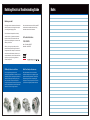
Charging & Starting System Testing Overview
Rotating Electrical Troubleshooting Guide
Key components to be tested
before removing the starter motor
Check connections
and cables.
Check drive belt condition,
tension, automatic belt tensioner.
Battery and
connections
Relay
Belt
Test the battery: right group
size, state of charge, load test.
Check operation of dash light
indicator or dash voltmeter.
Solenoid
Battery cables
Check for excessive
parasitic draw.
Check charging voltage
and amp output.
Battery
Switches
Identify and understand the key components
to the starting and charging system.
Need
Assistance?
Alternator
Tech Support: 800-854-0076
Email: [email protected]
Monday thru Friday 8AM – 8PM EST
Saturday 8AM – 4:30PM EST
Starter Motor
Remy International, Inc.
600 Corporation Drive
Pendleton, IN 46064 USA
remyinc.com
©2012 Remy International. Inc. I5-121
Rotating Electrical Troubleshooting Guide
Before you start
Each page contains information and instructions
that are important in assisting with the repair of
your starting and charging system.
Our technical assistance team at Remy are ASE
certified and have available the latest wiring
schematics and technical information.
Due to the electrical complexities of today’s
modern vehicles, it is important to determine
why the unit failed. This manual will be most
helpful in correctly finding the root cause of the
difficulty, the first time.
For Technical Assistance
At Remy, it is our goal to provide you with a
product that has passed the most severe and
stringent tests in the industry. To insure that the
starter motor and/or alternator perform to your
complete satisfaction, we have taken the necessary steps to provide you the guidelines to
achieve that objective.
1-800-854-0076
Mon - Fri: 8AM – 8PM EST
Sat: 8AM – 4:30PM EST
OEM Quality Alternators and Starters
World Class Quality and Engineering
Our vast engineering experience and
manufacturing capabilities are carried over to our
aftermarket products, providing the professional
installer with the highest industry quality in fit,
form, and function. Every unit must pass a
stringent computerized load test that monitors key
functions and parameters to simulate the actual
demands of “real life” driving conditions.
Remy differentiates itself from aftermarket
competitors through in-house engineering and
global manufacturing capabilities. World-Class
manufacturing processes incorporating ISO,
Six-Sigma and Lean principles insure each unit
is produced to the highest possible standards.
Notes
Contents
Electrical Essentials
1
2
Starter Motor
11
Belts, belt tensioner .................................... 2
Cranking circuit components .............................11
Battery ........................................................2
Aftermarket vs OE .............................................11
Battery, cables, connections .......................3
Starters: Where to begin? ..................................12
Excessive resistance & OHM’s Law ...........4
Does starter require a shim(s)?.....................13 -14
Connections .......................................................15
Alternator5
Cranking voltage at 2 locations ..........................15
Alternators: Where to begin?.......................5
Does starter have a good ground? ....................15
The Do’s & Don’ts .......................................6
Amp draw specs ................................................16
OE vs Aftermarket ......................................6
Analyze cranking voltage & amp draw ...............16
Amperage test ............................................7
Weak battery? Battery too small? ......................17
Alternator tests ...........................................7
Testing for excessive resistance (+) side ...........17
Not charging? Excessive resistance? .........8
Pinpoint tests on (+) side ...................................18
External voltage regulator test ....................9
Testing for excessive resistance (–) side ...........19
Causes of & testing for AC Ripple ..............10
Pinpoint tests on (–) side ...................................20
Overview .............................................. back cover
Tech Support: 800-854-0076
Belts
2
The alternator is only as good as the belt.
With the engine running, if dash indicator light stays
on or flashes erratically, check the following:
Are the belts:
1.Can pulley or fan be turned by hand due to loose or glazed belt? Belt will slip resulting in low output; dash light may stay on or flicker.
• Oil soaked?
2.Is the belt cracked or contaminated with oil, ATF,
coolant, etc?
3.Check for excessive noise from alternator. Could
be a loose, worn belt, or pulleys not aligned.
• Glazed/shiny?
• Correct tension?
• Cracked?
• Misaligned?
• Squealing?
Belt Tensioner
Automatic belt tensioners and idler pulleys do fail.
Belt tensioner:
Is the spring tension too tight? Too loose?
Belt stretched?
Check gauge on tensioner.
Battery
The battery is the heart of the system.
Starter motor “draws”
power from the battery.
Rotating Electrical Troubleshooting Guide
Alternator “generates”
electric current to replace
power lost and supply
vehicle electrical system.
Battery Testing
3
There are two key tests to determine condition of battery.
Battery condition:
State of charge test
The battery voltage
must be at least
12.4 volts before
load test.
Corrosion
12.6 v = 100%
12.4 v = 75%
12.2 v = 50%
12.0 v = 25%
11.8 v = 0%
State of Charge
State of Charge
State of Charge
State of Charge
State of Charge
Crack
Electrolyte
1. Plates covered with water?
3. Top of battery clean?
Load test
Load test simulates
the electrical demands
placed on the battery.
2. Is battery secure in tray?
4. Correct size for vehicle?
If load tester is not
available, have your
alternator/battery
supplier test the battery.
Battery Cables
Cables connect your alternator
and starter to the battery.
Lower gauge number allows for greater amperage flow.
Which cable will carry more power to the battery?
Carefully inspect cables for:
2 GA.
1. Signs of cracked insulation.
2. Too long or short. While attempting to crank engine, do battery cables
feel warm to the touch? If warm to the touch, cable gauge may be too small.
8 GA.
✔
✘
There are some cables sold with thick insulation and very little
copper. Look for gauge size printed on cable insulation.
Caution!
✘
Tech Support: 800-854-0076
Connections
4
Critically important.
Often overlooked, battery terminal ends and all cable connections are extremely vital
Temporary ends can dramatically shorten life of an
alternator or starter. How?
Temporary ends
Bare strands of copper wire under steel plates,
bolted to lead terminal ends, and exposed to
humidity equal corrosion.
•Apply correct terminal protection product.
Top post
•Far better to use molded/crimped style terminals.
•It is important that NO bare copper wire is exposed to the environment.
Clean connections?
Side terminal
Excessive Resistance
The starter and alternator are only as good as the connections.
Until you completely eliminate excessive resistance, your starter
and alternator will not function properly.
All connections should be metal to metal, clean and tight.
4 possibilities for resistance
PRESSURE
E
I R
N
LO
TA
RE
TF
Ohms
NC
CUR
Amps
E
Volts
W
RES
IS
Rotating Electrical Troubleshooting Guide
Alternators: Where to Begin
5
Symptoms
Possible Cause
Action Needed
No output from alternator
•Drive belt broken or loose
• Replace or tighten belt.
Dashboard indicator light
illuminates when key on,
engine off.
•Voltage not present at alternator B+ terminal
• Check fusible links and wire going to B+ terminal.
Dash board charging
indicator does not light
while key on, engine off.
•Blown fuse or fusible link
• Check and replace fuses as needed.
•Light bulb burned out
• Replace charging indicator light bulb.
•Corroded or loose connections
• Clean and tighten connections and perform voltage drop test.
Battery condition good
Low voltage output from
alternator
•No voltage signal to field through regulator plug
•Drive belt slipping
•Belt tensioner weak
• Check regulator plug for corrosion or melting. Replace pigtail if necessary.
• Use test gauge on belt to determine if replacement is needed.
• Check tensioner alignment marks for weakness.
•Cables corroded
•Improper body ground
Lights dim at idle while all
accessories are off.
•Drive belt slipping or tensioner is weak
•Improper engine rpm’s at idle
•Weak or defective battery
• Clean and tighten connections and perform volt drop test.
• Clean and tighten body ground.
• Check belt and tensioner for excessive wear.
• Refer to manufacturer’s specifications and repair if needed.
• Test battery and replace as needed.
Tech Support: 800-854-0076
B+ Terminal
6
Is battery voltage available at B+ terminal?
Insulator
1. Connection must be clean and tight at B+ terminal.
2. Do not over tighten and crack insulator.
3. Be careful not to strip threads.
4. Does wire from B+ terminal bolt connect to a fusible link at starter solenoid? If so, make sure the fusible link is clean
and tight.
B+ terminal
5. All brackets to alternator connections should be clean
metal-to-metal.
Note: Before removing alternator, make sure battery (–) cable is disconnected.
Removing either battery cable with engine
running will create a damaging voltage spike.
This was never a valid test for an alternator.
Voltage spikes and arcing are poison to the
electrical system.
Alternator and system management computers
may be damaged and or destroyed.
OE vs Aftermarket
Why doesn’t the replacement
alternator last as long as the
OE unit?
Answer:
Poor connections and excessive
voltage drop
Clean and tight connections insure
electrical system functions as designed.
Metal
chassis
Rotating Electrical Troubleshooting Guide
Engine
block
Amperage Test
7
Testing the alternator for AMP capacity.
1. Place AMP inductive clamp on heavy gauge wire(s) coming from back half of alternator.
AMPS
VOLTS
90
13.0
2. With engine at normal operating temp, and at high RPM’s, load engine down by turning up the load on the carbon pile tester amperage reading.
3. The unit is good if AMP output is within 80–100% rated output.
4. If AMP reading is low, it could be a bad alternator or excessive resistance may be in the charging circuit.
Note: Battery must
be fully charged
Alternator Tests
Voltage test.
This procedure does not apply to computer controlled
charging systems.
1. With voltmeter connected to battery, key and engine off, record “base” voltage reading:
________ volts.
Note: Battery should have minimum
of 12.4 volts.
2. Start engine and bring to normal operating temperature.
3. With engine at 1500 to 2000 RPM, turn on all electrical loads (lights, blower fan, A/C, etc.)
record volts: _________volts.
4. Charging voltage should be at least 0.5 volt
above base voltage reading. If not, excessive resistance could be present.
Tech Support: 800-854-0076
Voltage at the Alternator
8
Check charging voltage at alternator
(illustration to left) and then again
at battery (below test). This test
will determine if there is a problem
between the alternator and battery.
With engine running, 1500 to 2000 rpm, loads on:
1. Measure charging voltage at alternator, and
record: _______volts.
2. Measure open circuit voltage at battery, and
record: _______volts.
Engine block
3. If the difference is greater than 1 volt, there is a problem.
Voltage
Not charging?
Looking for excessive resistance on the (+) side:
•Voltmeter (+) test lead to alternator B+ terminal
•Voltmeter (–) test lead to battery (+) post
•Set voltmeter on lowest DC volt scale
•With engine running at 1500 to 2000 rpm, all loads on, measure and record voltage drop________.
Note: Should not exceed 0.5 volt drop. If voltage drop
exceeds 0.5 volt, check for:
• Corrosion
• Loose connections
• Frayed strands of wire
• Battery cable gauge too small
Rotating Electrical Troubleshooting Guide
Still Not Charging?
9
There is resistance in the charging circuit somewhere.
Couldn’t find the excessive resistance on the
(+) side? Let’s check the (–) side:
• Voltmeter (+) test lead to battery (–) post
.03
• Voltmeter (–) test lead to alternator case
• Set voltmeter on lowest DC volt scale.
• With engine running at 1500 to 2000 rpm,
all loads on, measure and record voltage drop:_______.
Note: Should not exceed 0.3 volt drop
If voltage drop exceeds 0.3 volt, check for:
• Corrosion
• Battery cable gauge too small
• Loose connections
• Frayed strands of wire
External Voltage Regulator
All alternators with external voltage regulators.
Regulator must have a good ground (
for alternator to function.
) in order
To determine if external voltage regulator is
properly grounded, follow these simple steps:
1. Engine running, no loads on
2. DVOM (+) lead to the regulator metal housing
3. DVOM (–) lead to battery (–) post
4. Set DVOM on lowest DC volt scale.
5. If reading is 0.1 volt (or 100mv) DC or above, the regulator does not have a
good ground.
6. Clean and retest for a good ground.
External voltage regulator
Tech Support: 800-854-0076
AC Ripple Voltage
10
What is AC voltage ripple and how does it
cause problems?
AC Voltage ripple is alternating current riding
on top of DC current
• Causes poor voltage source to modules:
ABS, ECU, PCM, etc.
• Modules need quality DC voltage source to make
accurate decisions, on the (+) side and (–) side.
• Changing amplitude of AC voltage ripple on top
of linear DC voltage can cause module to lose its
place in the engine run program.
Corrosion acts like a semi-conductor
causing DC voltage to fluctuate
• This results in:
• Erratic spark timing
• Missing fuel injector pulses
• Significant driveability problems
Excessive AC ripple caused by:
• Alternator: bad diodes or stator
• Corrosion at the battery or any connection
• Sulfated battery
AC Ripple Tests
What is the most accurate tester to measure for AC ripple?
Many have used an “Averaging” voltmeter. Some have graduated to an
“RMS” voltmeter.
However, due to changes in alternator
design technology, such as amount
of current produced, rotor shaft RPM,
stator windings, it is far more accurate
to use a Lab Scope.
Usage of a voltmeter, due to
the slow refresh rate, is not
an accurate test.
A scope will provide an actual
“footprint” of the AC Ripple, not just a voltage number.
Rotating Electrical Troubleshooting Guide
Lab Scope
Cranking Circuit
11
The following components have a profound effect on the starter and its ability to
crank the engine:
• Battery • Battery cables
• Relay/solenoid
• Neutral safety switch
• Alarm system
• Ignition switch
Connections
Why doesn’t the aftermarket starter motor last as long as OE?
Answer: Poor connections and excessive voltage drop
Potential
Problems
Note: the starter motor is
only as good as each one
of these connections.
Metal
chassis
Engine
block
Tech Support: 800-854-0076
Starters: Where to Begin
12
Symptoms
Possible Cause
Action Needed
•Dead battery
•Check battery state-of-charge.
•Loose connections
•Clean and tighten connections.
•Defective solenoid/mag switch, relay, neutral start switch or clutch switch
•Check and replace as needed.
•Defective fusible link
Engine will not crank.
Engine cranks too slow.
Starter keeps running.
Starter spins, but engine will
not crank.
Starter does not engage or
disengage properly.
•Defective ignition switch
•Replace fusible link.
•Check switch operation, replace as needed.
•Check engine.
•Mechanical problem in engine
•Problem in vehicle anti-theft system
•Check service manual for system tests.
•Weak battery
•Check battery state of charge.
•Defective starter motor
•Test starter.
•Mechanical problem with engine
•Diagnose engine problem and repair.
•Damaged pinion or ring gear
•Check gears for wear or damage.
•Defective ignition switch or control circuit
•Check switch and circuit components.
•Defective drive clutch
•Defective starting motor
•Rotate pinion by hand, it should not go both ways.
•Defective solenoid/mag switch
•Bench test starter, if passes check external switches / control circuit.
•Loose or corroded connections
•Defective starter or magnetic switch
•Damaged or worn pinion gear or ring gear
Rotating Electrical Troubleshooting Guide
•Clean and tighten connections.
•Test starter, and Magnetic switch.
•Test motor and verify drive extension.
•Check teeth on both drive and ring gear.
Starter Shims
13
Noisy, grinding starter “To shim or not to shim”.
In order for starter to operate efficiently and quietly, shimming
may be required, even if shims were not used on original
installation.
On some applications, you will have to either add shim(s) or
remove shim(s) to achieve correct “gap” (clearance).
Proper clearance between starter drive pinion gear and flywheel
ring gear is critical for correct operation of starter (See Fig. 1).
Fig. 1
To achieve correct gap between ring gear and starter drive,
usage of one or more shims may be required on certain GM
engines (See Fig. 2).
Fig. 2
Does your starter motor require a shim(s)?
Use your ears to listen for problem sounds.
Do you hear a high pitched whine or clanging sound while
cranking, before engine starts?
Gap too loose?
Problem: excessive clearance
Starter must be shimmed closer (into) ring gear to reduce gap
(clearance).
Remove any existing shims.
Start with one .015” shim cut in half on outboard bolt only
(the bolt on outside of starter motor away from engine)
See Fig. 3.
Engine Block
Half shim
GAP
This will move starter closer into the ring gear.
Outboard bolt
Fig. 3
Tech Support: 800-854-0076
Starter Shims
14
Does your starter motor require a shim(s)?
Gap too tight?
Use your ears to listen for problem sounds.
Engine Block
Do you hear a high pitched whine after engine starts, as key
is being released?
Problem: not enough clearance.
Starter must be shimmed away from ring gear to increase
gap (clearance).
Shim
GAP
Install one .015” shim across both bolt holes to increase
gap (See Fig. 4)
Fig. 4
OR
Install one .015” shim cut in half or a substitute shim on
inboard bolt only; the bolt on inside of starter motor closest
to engine (See Fig. 5).
Outboard bolt
Engine Block
Usage of one shim on inboard bolt only, will provide
greater clearance.
Half shim
Note: Do not use more than 3 shims on either side.
GAP
When installing replacement starter motor
DO NOT use an impact gun or breaker bar to tighten bolts! Nose
cones are made of aluminum and are very easy to distort or crack by
over tightening.
Fig. 5
Inboard bolt
• Always reinstall any existing heat shields and rear support brackets.
• Make sure all connections at solenoid are clean and tight.
• Add or remove shims one at a time to avoid damage.
Providing the proper gap will award you with a quiet starter and a longer life
Rotating Electrical Troubleshooting Guide
Cables and Connections
Too hot to handle?
15
Check connections
While cranking, if either battery cable
feels hot, gauge of cable may be too
small or too long or possibly a short
within the starter. When replacing
battery cables, always use shortest,
heaviest gauge cables possible.
Right
Terminal end is pressed down
completely over battery post.
Wrong
Terminal end is not
properly seated.
Cranking Voltage
At two locations?
While Cranking:
10.7 volts
– 9.2 volts
1.5 volts
If the difference is greater than 1 volt,
excessive resistance is present.
Excessive resistance could be on the
+ or – side or the side of the cranking
circuit.
To prevent engine from starting, some
vehicles may not start with (WOT)
See manufacturer’s service manual.
PROBLEM!
Good Ground?
The starter motor is grounded to engine block.
Engine must have a good ground through the
battery cable back to battery (–) terminal in
order to crank.
•To prevent engine from starting, some vehicles may not start with (WOT). See manufacturer’s service manual
•With voltmeter test leads as shown, measure and record voltage while cranking: ________ volt.
•If voltage exceeds 0.2 volt, there is a poor ground in
(–) cable or connections.
Tech Support: 800-854-0076
Amp Draw Specs
16
“Approximate” amp draw specifications.
Engine Size
Amp Draw
Cubic Inches
Liters
100 to 200
1.6 to 3.2
100 to 200
200 to 350
3.2 to 5.6
125 to 250
350 to 500
5.6 to 8.0
150 to 300
There is no fixed amperage draw for every engine
Why?
• Engine size
• Compression
•Weight (viscosity) of oil
• Mechanical condition of engine
• Carbon buildup • Design of starter motor
• High torque, low torque, gear reduction, etc.
All have an impact on amperage draw.
Analyze Cranking Voltage & Amperage
Problem: high mechanical resistance, resulting in high amp draw.
Amps
High
Volts
Low
• Carbon build up on top of pistons
• Wrong weight oil
• Cable that is shorted to ground
• Bad starter
Possible causes:
Problem: high electrical resistance,
resulting in low amp draw.
Volts
Normal
Amps
Low
Possible causes:
• Loose connections
• Frayed cables, etc.
• Corrosion
• Cable gauge too small resulting in high resistance
• Binding engine
Problem:
Amps
High
A weak or undersized battery resulting in:
• Low cranking voltage
• Destroyed starter
• Slower spinning armature causing
starter to draw excessive amps
Rotating Electrical Troubleshooting Guide
Volts
Low
Weak Battery?
17
A weak or undersized battery will cause high amp draw.
Weak battery
• Voltage drops to 9.5 volts while cranking
• Example: starter motor needs 2095 watts
• Volts x AMPS = watts
• How many amps will this starter motor now need in order to crank?
• 2095 watts
Weak battery
9.5 volts = 220 AMPS
Strong battery
• Voltage drops to 11.2 volts while cranking
• Example: starter motor needs 2095 watts
• How many AMPS will this starter motor now need in order to crank?
• 2095 watts
11.2 volts = 187 AMPS
Strong battery
Testing (+) Side
Testing for excessive resistance on the (+) side.
1. Must have fully charged battery
2. To prevent engine from starting, some vehicles may not start with (WOT). See manufacturer’s service manual.
3. Set DVOM on lowest volt scale.
4. DVOM (+) lead to battery (+) post
5. DVOM (–) lead to battery terminal stud on starter
6. While cranking engine over, record ________voltage drop (excessive resistance).
7. If voltage drop exceeds 0.5 volt, clean all connections between battery & starter.
Metal
chassis
Engine
block
Tech Support: 800-854-0076
Positive Side (+)
18
Starter motor pinpoint tests on positive side.
1.Must have fully charged battery
2.To prevent engine from starting, some vehicles may not start with (WOT).
See manufacturer’s service manual.
3.Set DVOM on 2 volt scale or lowest volt scale.
4.Engine at normal operating temp
5.The following pinpoint tests will show you exactly where the excessive voltage drop is located.
___________Maximum v/drop 0.00
___________Maximum v/drop 0.20
___________Maximum v/drop 0.20
___________Maximum v/drop 0.20 Rotating Electrical Troubleshooting Guide
Amperage
19
Amperage must flow in a complete circuit.
Why test for excessive resistance on the (–) side?
Ohm’s Law states: Amperage out, amperage in
Bolted to engine block
All amps that reach the starter motor, must return to battery (–) post.
Excessive resistance could be anywhere within the (–) path.
The starter motor is grounded through the nose housing to engine block.
This connection must be clean and tight.
Testing (–) Side
Testing for excessive resistance on the (–) side.
1. Must have fully charged battery
2. To prevent engine from starting, some vehicles may not start with (WOT).
See manufacturer’s service manual.
3. Set DVOM on lowest volt scale.
4. DVOM (+) lead to clean metal spot on starter
5. DVOM (–) lead to battery (–) terminal
6. While cranking engine over, record ________voltage drop (excessive resistance).
7. If voltage drop exceeds 0.3 volt, clean all connections between battery and starter.
Tech Support: 800-854-0076
Negative Side (–)
20
Starter motor pinpoint tests on negative side.
1.Must have fully charged battery.
2.To prevent engine from starting, some vehicles may not start with (WOT).
See manufacturer’s service manual.
3.Set DVOM on 2 volt scale or lowest volt scale.
4.Engine at normal operating temp.
5.The following pinpoint tests will show you exactly where the excessive voltage drop is located.
Junction:
solenoid or relay
___________Maximum v/drop 0.30
Rotating Electrical Troubleshooting Guide
Starter
terminal
Engine block
___________Maximum v/drop 0.20
___________Maximum v/drop 0.00
Before You Start
Please read carefully for maximum results from this manual
Each page contains information and instructions
that are most important in assisting with the
repair of your cranking and/or charging problem.
Due to the electrical complexities of today’s
modern vehicles, it is important to determine
Why the previous unit failed. This manual and
the implementation of the procedures described
therein, will be most helpful in correctly finding
the root cause of the difficulty, the first time.
At Remy, it is our goal to provide you with a
product that has passed the most severe and
stringent tests in the industry. To insure that the
starter motor and/or alternator perform to your
complete satisfaction, we have taken the
necessary steps to provide you the guide lines to
achieve that objective. In addition, we have
provided below our technical assistance contact
information to further help you troubleshoot your
cranking or charging problem.
Our technical assistance team at Remy are ASE
certified. They have available the latest wiring
schematics and technical information.
For Technical Assistance
1-800-854-0076
Mon - Fri: 7AM – 7PM CST
Sat: 7AM – 3:30PM CST
OEM Quality Alternators and Starters
World Class Quality and Engineering
Our vast engineering experience and
manufacturing capabilities are carried over to our
aftermarket products, providing the professional
installer with the highest industry quality in fit,
form, and function. Every unit must pass a
stringent computerized load test that monitors key
functions and parameters to simulate the actual
demands of “real life” driving conditions.
Remy differentiates itself from aftermarket
competitors through in-house engineering and
global manufacturing capabilities. World-Class
manufacturing processes incorporating ISO,
Six-Sigma and Lean principles insure each unit
is produced to the highest possible standards.
Notes
Charging & Starting System Testing Overview
Rotating Electrical Troubleshooting Guide
Key components to be tested
before removing the starter motor
Check connections
and cables.
Check drive belt condition,
tension, automatic belt tensioner.
Battery and
connections
Relay
Belt
Test the battery: right group
size, state of charge, load test.
Check operation of dash light
indicator or dash voltmeter.
Solenoid
Battery cables
Check for excessive
parasitic draw.
Check charging voltage
and amp output.
Battery
Switches
Identify and understand the key components
to the starting and charging system.
Need
Assistance?
Alternator
Tech Support: 800-854-0076
Email: [email protected]
Monday thru Friday 8AM – 8PM EST
Saturday 8AM – 4:30PM EST
Starter Motor
Remy International, Inc.
600 Corporation Drive
Pendleton, IN 46064 USA
remyinc.com
©2012 Remy International. Inc. I5-121