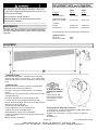
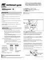
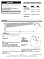
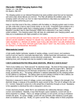
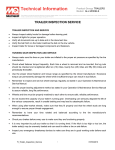
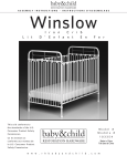
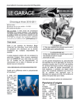
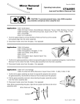
1
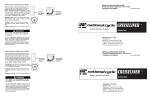
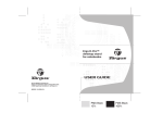
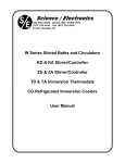
INSTALLATION AND OWNER’S MANUAL
N928 or N928E (European) LIGHT BAR for
Suzuki® VS800 Intruder Pages 1 and 2
Suzuki® VZ800 Marauder Pages 3 and 4
PARTS LIST
Description
Lightbar Assembly, N928 or N928E
Connectors, Scotchlok
Screwdriver, #2 Phillips
Hex Key, 5mm
Socket, 10mm, and Ratchet Wrench
Pliers, Slip Joint
Plus tools required for removal of Upper Triple
Clamp
Qty.
1
6
PREPARATION
1. Make certain the motorcycle is securely positioned for this
installation. Cover the front fender with a protective cloth to avoid
scratches.
2. Remove Headlight from Headlight Shell (Screwdriver). Set
aside.
NOTE: this installation for the VS800 Intruder requires removal
and reinstallation of the upper Triple Clamp. Refer to your Service
Manual for the proper tools and procedure.
NOTE: right and left on the motorcycle are determined from
the rider’s position.
3. Unplug Turn signal wires and pull them out of the Headlight
Shell.
4. Loosen clamping screws on Turn signal mounting clamps (Hex
Key, 5mm).
5. Remove Upper Triple Clamp, Refer to Service Manual
6. Slide Turnsignals up fork tubes and remove. Set aside, they
will not be reused.
Position light bar
assembly between
the lower triple
clamp and the head
light shell mounting
bracket.
7. Reinstall Upper Triple Clamp per Service Manual.
INSTALLATION
1. Mount the Light Bar Assembly:
A. Cover the front fender to protect it from damage.
B. Remove the nuts from the Headlight Shell mounting
screws (10mm Socket), set aside. Let the Horn hang
from its wires.
C. Lift the Headlight Shell until the mounting screws are
removed from the lower Triple Clamp.
D. Hold the Light Bar assembly in place on the lower
Triple Clamp and reinstall the Headlight Shell and Horn.
Tighten the nuts to manufacturer's specified torque.
2. Wire the Light Bar Assembly:
A. Route the Light Bar Assembly wires over the lower
TripleClamp and into the Headlight Shell.
B. Attach the Light Bar Assembly wires per the following
list;
NOTE: Grounding is through the frame.
Light Bar
Motorcycle
Turnsignal, Left
Short Red
Light Green
Turnsignal, Right
Short Red
Black
Running Light, Left
Short Black
Grey
Running Light, Right
Short Black
Grey
Passing Lamps
Long Blue
White (High Beam)
Ground
Note, Light Bar Wiring Helpful Hints:
The long Blue wire is the main power wire for the spotlights on
the light bar. Connect that to the main power source from the
headlight. Either the High Beam wire or the Low Beam wire.
The choice is your preference. Turn on bike and Check.
The two short RED wires are for the turn signals. One RED wire
for the Left side turn signal and one for the Right side turn signal. Turn on bike and check.
The two short BLACK wires are for the running lights. One
BLACK wire for the Left side running light and one for the Right
side running light. Turn on bike and check.
The Light Bar attached to the front fork of the motorcycle serves
as the ground in most cases. A precautionary step to insure
proper grounding is to take one of the Green Ground wires from
the existing turn signals and ground that between the Light Bar
Mount and the Triple Tree Bracket.
Always start by doing one side at a time. Preferably the right
side or high side of the bike first.
Black/White
11. Reinstall the headlight and rim
Wire From Light Bar
Insert To Stop.
NOTE: Check local regulations for proper passing lamp
operation. Some states require passing lamps be lit only
with hi-beam.
Through Wire
Page 1 of 4
10-110728-000 Rev. A 04/02
REPLACEMENT PARTS and ACCESSORIES
Order parts through your local dealer or contact National Cycle.
After wiring the light bar check for clearance. Make sure
the wires can not get pinched when the fork is turned to a
full fork lock left and right.
Description
N928
Part No.
N928E
Part No.
Check all lights for proper operation.
Light Head Assembly
90-910501-000
90-910501-000
Lamp Assembly E13/DOT
Reflector, Lens and Bulb
90-901011-000
90-901011-000
Turn Signal
Assembly
90-930921-000
90-930921-000
Turn Signal Lens
90-930213-000
90-930213-000
Check the tightness of all fasterners that have been
involved in this installation.
MAINTENANCE
The high quality chrome finish of your National Cycle light
bar can be maintained with any quality chrome cleaner and
/or polish.
Turn Signal Bulb Only: Bulb 1157 Available at Most Auto Parts Stores.
Light Bar Accessories
Chrome Visor
Alternate Thumb Switch
N9005
N9001
ADJUSTMENT
1. HORIZONTAL AIM
A.To adjust the Spotlights or Turnsignals right or left gently
rotate the lamp into the correct position. In the event that the
lamps become loose, refer to the procedure for vertical adjustment.
2. VERTICAL AIM
A. Disconnect wire connections inside the Headlight Shell.
B. Pull the wires out of the Light Bar tube.
C. Turn the Turn signal to provide access to the mounting
screws.
D. Unscrew the Turn signal mounting screws and remove the
Turnsignal (Hex Key).
E. Push the Spotlight wire up into the Spotlight Shell.
F. Loosen the nut on the Spotlight stud (Deep Socket).
G. Now, adjust the Spotlight. Reconnect the spotlight wire and
illuminate to verify its projection.
H. Push wire into the Spotlight Shell.
I. Firmly retighten the nut on the Spotlight stud.
J. Pull the wire out of the Spotlight Shell.
K. Reassemble in reverse order of disassembly.
L. Adjust the Spotlights and Turn signals horizontally by rotating into position.
M.Verify operation of the lights.
E
To adjust vertical aim you
will need these additional
tools:
Hex Key, 5/32" or 4mm
Deep Socket and Socket,
9/16" (14mm) or a 9/16”
Slotted Socket.
Installing optional N9005 Light Head Visor.
1. Loosen the rim of the light head assembly. (Phillips Screw Driver).
2. Slip taps of Visor under rim. Item E.
3. Shape Visor / Visor Tabs to conform to contours of light head
assembly.
4. Retighten rim.
Page 2 of 4
10-110728-000 Rev. A 04/02
©2001 National Cycle, Inc. PO Box 158, Maywood, IL 60153-0158 USA
708-343-0400 / Fax: 708-343-0625 / www.nationalcycle.com / e mail: [email protected]
INSTALLATION AND OWNER’S MANUAL
N928 or N928E (European) LIGHT BAR for
Suzuki® VZ800 Marauder Pages 3 and 4
PARTS LIST
Description
Lightbar Assembly, N928 or N928E
Connectors, Scotchlok
Screwdriver, #2 Phillips
Screwdriver, #3 Phillips
Socket, 10mm, and Ratchet Wrench
Pliers, Slip Joint
Qty.
1
6
PREPARATION
1. Make certain the motorcycle is securely positioned for this
installation. Cover the front fender with a protective cloth to avoid
scratches.
NOTE: right and left on the motorcycle are determined from
the rider’s position.
2. Remove Headlight from Headlight Shell (Screwdriver). Set
aside.
3. Unplug Turn signal wires and pull them out of the Headlight
Shell.
4. Loosen clamping screws on Turn signal mounting clamps (Hex
Key, 5mm).
5. Remove Upper Triple Clamp, Refer to Service Manual
6. Slide Turnsignals up fork tubes and remove. Set aside, they
will not be reused.
Position light bar
assembly between
the lower triple
clamp and the head
light shell mounting
bracket.
7. Reinstall Upper Triple Clamp per Service Manual.
INSTALLATION
1. Mount the Light Bar Assembly:
A. Cover the front fender to protect it from damage.
B. Remove the nuts from the Headlight Shell mounting
screws (10mm Socket), set aside. Let the Horn hang
from its wires.
C. Lift the Headlight Shell until the mounting screws are
removed from the lower Triple Clamp.
D. Hold the Light Bar assembly in place on the lower
Triple Clamp and reinstall the Headlight Shell and Horn.
Tighten the nuts to manufacturer's specified torque.
2. Wire the Light Bar Assembly:
A. Route the Light Bar Assembly wires over the lower
TripleClamp and into the Headlight Shell.
B. Attach the Light Bar Assembly wires per the following
list;
NOTE: Grounding is through the frame.
Light Bar
Motorcycle
Turnsignal, Left
Short Red
Light Green
Turnsignal, Right
Short Red
Black
Running Light, Left
Short Black
Grey
Running Light, Right
Short Black
Grey
Passing Lamps
Long Blue
White (High Beam)
Ground
Note, Light Bar Wiring Helpful Hints:
The long Blue wire is the main power wire for the spotlights on
the light bar. Connect that to the main power source from the
headlight. Either the High Beam wire or the Low Beam wire.
The choice is your preference. Turn on bike and Check.
The two short RED wires are for the turn signals. One RED wire
for the Left side turn signal and one for the Right side turn signal. Turn on bike and check.
The two short BLACK wires are for the running lights. One
BLACK wire for the Left side running light and one for the Right
side running light. Turn on bike and check.
The Light Bar attached to the front fork of the motorcycle serves
as the ground in most cases. A precautionary step to insure
proper grounding is to take one of the Green Ground wires from
the existing turn signals and ground that between the Light Bar
Mount and the Triple Tree Bracket.
Always start by doing one side at a time. Preferably the right
side or high side of the bike first.
Black/White
11. Reinstall the headlight and rim
NOTE: Check local regulations for proper passing lamp
operation. Some states require passing lamps be lit only
with hi-beam.
Wire From Light Bar
Insert To Stop.
Through Wire
Page 3 of 4
10-110728-000 Rev. A 04/02
REPLACEMENT PARTS and ACCESSORIES
Order parts through your local dealer or contact National Cycle.
After wiring the light bar check for clearance. Make sure
the wires can not get pinched when the fork is turned to a
full fork lock left and right.
Description
N928
Part No.
N928E
Part No.
Check all lights for proper operation.
Light Head Assembly
90-910501-000
90-910501-000
Check the tightness of all fasterners that have been
involved in this installation.
Lamp Assembly E13/DOT
Reflector, Lens and Bulb
90-901011-000
90-901011-000
MAINTENANCE
Turn Signal
Assembly
90-930921-000
90-930921-000
Turn Signal Lens
90-930213-000
90-930213-000
The high quality chrome finish of your National Cycle light
bar can be maintained with any quality chrome cleaner and
/or polish.
Turn Signal Bulb Only: Bulb 1157 Available at Most Auto Parts Stores.
Light Bar Accessories
Chrome Visor
Alternate Thumb Switch
N9005
N9001
ADJUSTMENT
1. HORIZONTAL AIM
A.To adjust the Spotlights or Turnsignals right or left gently
rotate the lamp into the correct position. In the event that the
lamps become loose, refer to the procedure for vertical adjustment.
2. VERTICAL AIM
A. Disconnect wire connections inside the Headlight Shell.
B. Pull the wires out of the Light Bar tube.
C. Turn the Turn signal to provide access to the mounting
screws.
D. Unscrew the Turn signal mounting screws and remove the
Turnsignal (Hex Key).
E. Push the Spotlight wire up into the Spotlight Shell.
F. Loosen the nut on the Spotlight stud (Deep Socket).
G. Now, adjust the Spotlight. Reconnect the spotlight wire and
illuminate to verify its projection.
H. Push wire into the Spotlight Shell.
I. Firmly retighten the nut on the Spotlight stud.
J. Pull the wire out of the Spotlight Shell.
K. Reassemble in reverse order of disassembly.
L. Adjust the Spotlights and Turn signals horizontally by rotating into position.
M.Verify operation of the lights.
E
To adjust vertical aim you
will need these additional
tools:
Hex Key, 5/32" or 4mm
Deep Socket and Socket,
9/16" (14mm) or a 9/16”
Slotted Socket.
Installing optional N9005 Light Head Visor.
1. Loosen the rim of the light head assembly. (Phillips Screw Driver).
2. Slip taps of Visor under rim. Item E.
3. Shape Visor / Visor Tabs to conform to contours of light head
assembly.
4. Retighten rim.
Page 4 of 4
10-110728-000 Rev A. 04/02
04/02©2001 National Cycle, Inc. PO Box 158, Maywood, IL 60153-0158 USA
708-343-0400 / Fax: 708-343-0625 / www.nationalcycle.com / e mail: [email protected]