1
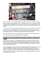
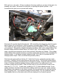
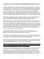
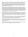
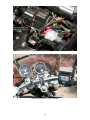
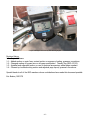
Marauder VZ800 Charging System FAQ
Version 1.4 – July 2008
Eric Boehm, MIG 379
The charging system on our beloved Marauders has some problem areas that can be improved,
and some areas where failures are common. This FAQ will address the problem areas in the
charging system and show you how to make improvements to help keep your battery and
electrical system performing up to par.
Keep in mind that most of the time, problems with the battery or charging system seem to show
up with a bike that is hard to start (cranks slowly or not at all). Frequently these problems are a
starting system problem rather than a charging system or battery problem. Please read over
Boydster’s excellent Hard to Start Marauder VZ800 FAQ to determine if you have a starting
system problem. This charging system FAQ will help you understand your charging system, and
help you to troubleshoot and repair problems in the system.
USE CAUTION AROUND ELECTRICAL CIRCUITS. YOU WILL BE DEALING WITH BATTERY POWER,
WHICH CAN BE POWERFUL ENOUGH TO INJURE YOU, DAMAGE YOUR BIKE OR START A FIRE IF
USED INCORRECTLY. BEWARE OF WHERE YOUR TOOLS ARE AND WHAT YOU ARE WORKING ON
AT ALL TIMES. IF YOU HAVE FURTHER QUESTIONS ABOUT WHAT YOU ARE DOING, ASK ON MIG
OR CONSULT A PROFESSIONAL MECHANIC.
What tools do I need?
A high quality digital multimeter capable of reading voltage, current (amps), and resistance
(ohms) is all you need for most tests described here. Simple hand tools (screwdrivers, wrenches,
sockets, allens, etc.) are needed to access electrical components. Wire cutters, strippers,
soldering irons, and crimping tools may be needed to make repairs.
I don’t understand the first thing about electricity. What do I need to know?
Think of your battery as a “bank account” for electrical charge. The level of that charge (account
balance) is measured as the voltage on the battery terminals (with the engine OFF). Electrical
energy is used (withdrawn) by the electrical components on the bike (lights, ignition, fan, fuel
pump, accessories, etc.). The energy withdrawn is replaced (deposited) by the charging system
so that balance is maintained. The battery-bank account analogy is limited in that a battery can
only hold so much charge and after it is “full” cannot accept any more.
Electricity is measured in terms of voltage, current, and resistance. Voltage is the strength of an
electrical charge, a measure of its potential to cause current to flow. The unit of voltage is the volt
(V). Current, measured in amps (A), is the actual flow of electricity through a circuit. Resistance
is the opposition to electrical flow and is measured in ohms (Ω).
A basic electrical principle, called Ohm’s Law establishes the relationship between voltage,
current, and resistance. Basically, it says that through a given resistance, current will vary in
direct proportion to voltage. That is, as voltage increases, so will current, as long as resistance
remains the same. At a given voltage, current will vary inversely with resistance (current goes
down as resistance goes up). Finally, at a given current flow, voltage varies in direct proportion
-1-
with resistance (as resistance goes up, voltage goes up). Ohms law is expressed mathematically
as E (voltage) = I (current) X R (resistance). Rearranging to solve for whatever is needed, we
get E=I x R, I = E/R, and R = E/I.
A simple understanding of the concepts of power and energy will also be helpful here. Power is
the ability of electricity to do work (e.g., light your headlight) and is measured in watts. It is a
function of voltage and current and is expressed mathematically as P (power) = E x I.
Energy can be thought of as power consumed over a period of time. The basic unit of energy is
the joule. This is equal to one watt over one second of time and is sometimes called a wattsecond. The unit of energy used on your electric bill at home is the kilowatt-hour, equivalent to
1000W used for 1 hour. If your headlight is a 60W model, then at a voltage of 12V, it should
have 5A of current flowing (12V x 5A = 60W). In one hour of use, it should consume 60 watthours of energy.
Batteries have three ratings commonly associated with them. First is the voltage. Most bike and
car batteries are nominally rated at 12V, fully charged (it will actually be between 12.2V and
12.6V depending on the battery). Next is the Amp-Hour (Ah) rating and the third is Cold Cranking
Amps (CCA). The Amp-Hour rating is a measure of how much charge the battery can store. The
Marauder’s battery is specified at 12V 10Ah (12 volts, 10 amp-hours), which means that one could
theoretically supply a load drawing 10A at 12V for one hour. Your 60W headlight drawing 5A
should run down the battery in 2 hours. The CCA is the number of amps of current the battery is
capable of instantly supplying when cold and is a measure of how much current it could
theoretically supply to the starter.
What are the parts of the charging system?
There are three major components in the charging system: The generator (stator and rotor), the
regulator/rectifier module, and the battery. The generator (alternator) converts the engine’s
mechanical energy into alternating current (AC) electrical energy. The regulator/rectifier converts
the AC energy from the generator into direct current (DC) used in the rest of the bike’s electrical
system and regulates the voltage of that energy, providing power to charge the battery and
supply the bike’s other electrical needs. Regulation is necessary to avoid overcharging the battery
and damaging electrical components. The battery stores energy to start the bike and to provide
power when the generator’s output falls below the bike’s requirements.
Where are the charging system components located? How are they connected
together?
The generator (alternator) on the Marauder is located inside the left-hand (LH) side of the engine.
It consists of a rotor – a set of magnets on an arm at the end of the engine’s crankshaft that
rotates as the engine turns – and a stator – a set of electrical coils that are mounted to the inside
of the left engine case. The coils of the stator are connected to the electrical system via three
yellow wires that exit from the engine case. These wires are routed to a connector under the LH
side cover. They then go to a connector under the right-hand (RH) side cover where they plug
into the lead to the regulator/rectifier.
-2-
The regulator/rectifier is a sealed unit mounted to a tab under the bike, ahead of the rear wheel.
Its wiring is routed to the area under the RH side cover where it connects to the wires coming
from the generator and the rest of the electrical system.
DC power from the regulator/rectifier is carried back to the wiring harness on a red (R) wire,
which is the positive side, and a black with white tracer (B/W) wire, which is the negative or
ground side. These wires connect to the bike’s wiring harness at a connector under the RH side
cover.
On 1997 and 1998 models, the red wire from the regulator/rectifier connector joins the red main
power wire on the bike in the wiring harness where it is simply spliced together with a clamp.
The red main power wire then goes to the key switch (and ultimately to the rest of the electrical
system) and to a connector on the starter relay under the LH side cover. On the 1999 and later
models, the red wire from the regulator/rectifier connector is also routed to the starter relay
connector where it joins the main power wire (the connection is made on a U shaped pin inside
the starter relay socket). Therefore, on 1997 & 1998 models, there will be one red wire going to
the connector on the starter relay. On 1999 and later models, there will be two red wires (main
power lead and lead from the regulator/rectifier). There are also a yellow/black (Y/B) wire and a
black/white (B/W) wire at this connector. These are part of the starting circuit.
The connection from the red wire(s) is routed through the starter relay housing to the 30A main
fuse (located under the green or white cover) and then to the heavy red positive cable coming
from the battery. It should be noted here that the starter relay serves no purpose in the charging
circuit other than a convenient place to tie the main power wire through the main fuse to the
battery.
Power from the regulator/rectifier and power from the battery are combined together on the main
red power wire. The 30A main fuse protects all of the bike’s wiring from an overload on this wire.
The battery is located under the tool tray beneath the rider’s seat. It is accessed by removing the
seat and the tool tray. Most of the tests in this FAQ can be done with the battery installed.
How does the charging system work?
Energy used to start the bike is stored in the battery. Some of that energy is borrowed from the
battery to crank the starter and get the engine running. Once the engine is running, the
generator (stator) provides energy to replace the charge borrowed from the battery and to power
the bike’s electrical system and accessories.
With the engine running, the crankshaft rotates and the rotor magnets pass over the stator coils,
generating an alternating electrical voltage (AC). The faster the engine turns, the stronger (and
higher in frequency) the voltage gets. There are three coils on the stator located 120 degrees
apart. The stator generates three AC voltages separated in phase by 120 degrees. The three
phases of AC are carried out of the engine case on a set of three yellow wires. This AC voltage is
carried to the regulator/rectifier where it is converted to DC (rectified) and regulated to the
correct voltage.
-3-
When the engine is idling, the rectifier portion of the regulator/rectifier converts the AC coming
from the stator into DC and passes it directly to the battery and the rest of the electrical system
without regulating it. If the bike’s electrical loads are low (cooling fan not running, accessories
such as spot lights & heated grips/clothes are turned off), this idling power can charge the battery
if needed. If the electrical loads are high, energy will be borrowed from the battery, as this
unregulated power will not be enough to meet all of the needs of the bike. Thus, when idling, the
battery may be drained by heavy electrical loads.
As the engine speed increases, the voltage to the battery will increase until it reaches a preset
point (about 13.5V-13.8V). At this time, the regulator will turn on and prevent the voltage from
going higher. If the battery is not fully charged, current will flow into the battery and energy
“borrowed” from the battery will be replaced. It is important to understand that if the battery is
very low on charge level, it will place a high load on the output of the charging system and the
terminal voltage (voltage measured from the battery + to – terminals) will be lower than the
13.5V-13.8V setting on the regulator, even with the engine turning at high RPM. As the battery
nears a fully charged state, the terminal voltage will approach the cut-off point on the regulator
and should then remain at or near the 13.8V mark.
How much accessory load can my bike handle? Can I run spot lights or heated
clothes?
It is important to understand that the charging system has a limited amount of power that it can
produce. This is the maximum “wattage” of the system. Assuming a fully charged battery, there
is some spare power available to run things like accessory lights, heated grips, electric gloves, etc.
If the maximum output of the charging system is exceeded, current will be drawn from the
battery to power the bike for as long as the battery lasts. If the system is severely overloaded,
damage to the regulator/rectifier or generator stator could occur.
The Marauder service manual specifies the output of the stator as 250W at 5000RPM. Adding up
the wattage of all stock lighting that runs constantly (headlight 60W, running lights 10W, tail light
5W, and speedo light at about 2W) gives about 77W. The power used by the fuel pump and
ignition are not specified, but I have measured the total current draw from the battery at about
12-13A with the engine running and the stator disconnected. That works out to about 150W total
power. Subtract the 77W for lighting means that the ignition and fuel pump consume about 75W
total.
Subtracting 150W of total power demand on the stock bike from the 250W max stator output
leaves about 100W of “spare” capacity at 5000RPM (which works out to 78MPH with stock
gearing, faster with 16 or 17 tooth front sprockets). Remember, there will be considerably less
extra power at lower RPM. Keep in mind that the radiator fan, brake light and turn signals will
add additional power demands when they are on.
To determine if you can run a particular accessory or accessories, add up the wattage rating of all
accessories you plan to run. If that number is less than 100W, you should be fine with highway
riding (e.g., 2 spotlights at 35W each = 70W). If you plan on doing a lot of riding at lower
speeds, such as parade duty, it would be best to avoid running high wattage accessories.
Electronics like GPS, radios, etc., only draw a few watts and can be used even when idling for
long periods.
-4-
I run an electric heated jacket liner and gloves in the wintertime. Their total draw runs about
104W (liner 77W, gloves 27W). In more moderate temperatures, I’ll use only the liner without
the gloves. I use a variable controller, which pulses the power to the clothes on and off to keep
the temperature comfortable. The controller limits the amount of power used over time, but the
“on” time power consumption is still right at max.
When riding on the highway using both liner and gloves, I do notice the slightest drop in battery
voltage each time the controller pulses on. At slower speeds, the drop is pretty sharp, but of
course, with the lower wind speed, I can turn it down and still be comfortable. When running the
liner without the gloves, I really don’t notice much voltage drop except at idle.
It is important to note here that if your charging system is not working well, high load accessories
like lighting and heated clothes will make the problem much worse. You could wind up stuck with
a dead battery out on the road. Be sure your charging system is working well before running
high draw accessories.
My battery is weak; my bike is hard to start or won’t start. What’s the problem?
First, you need to be sure that your battery really is weak. Slow cranking can be a sign of a weak
or poorly charged battery, but it can easily be a problem with the starting circuit as well. Even if
the bike starts quickly when jumping the battery from a car, this doesn’t rule out starter circuit
troubles. See Boydster’s Hard to Start Marauder VZ800 FAQ for more information.
The first thing we need to do is make sure the battery is fully charged. If you have a battery
charger, now would be the time to hook it up. You really need to use a charger capable of at
least 2 amps of charging current. A 10-amp charger would be a better choice. For
troubleshooting purposes, avoid the small wall-wart type trickle chargers like the Battery Tender
Jr. They are great for storing batteries, but take far too long to charge a discharged battery.
Remember that the Marauder uses a 10Ah battery, so expect to spend about 5 hours charging
with a 2-amp charger. A 10-amp charger requires a little over an hour for a full charge.
OK, my battery charger has been on for XX hours, the light is green, the meter on the
charger says full, etc. It still cranks weakly. Now what?
Disconnect the charger before making any further tests. If your lights shine brightly when the
key is on, your battery has at least some charge (it’s not dead). Remove your seat and tool tray.
Flip up the little red plastic cover over the positive (+) terminal on the battery. With the key in
the OFF position, set your multimeter to VDC (DC Volts). Place the red lead on the positive
terminal of the battery and the black lead on the negative (see photo below). The voltage should
read at least 12.2V – 12.6V. If the voltage reading is lower than this, double check that the key is
off (this is a no-load test). If the key is off and the battery voltage is still low, disconnect the
negative cable from the battery and check the voltage again. If it is still low, your battery
probably has a bad cell and should be replaced.
-5-
Battery Connections (with accessories)
Next, turn the key on. The headlight should shine brightly. Measure the voltage on the battery
again. It should not be less than about 11.9V. Keep the key on for about 3-5 minutes and check
the voltage again. It should still be in the range of 11.8-11.9V (this is a simple load test). If the
voltage drops significantly after only a few minutes, the battery is probably weak and should be
replaced.
You may also want to consider having the battery load tested. Many auto parts stores will do this
for you for free. Just bring the battery in. They will connect it to a tester that places a much
greater current load on the battery (similar to starting the engine) and determines if the battery
can still maintain voltage. If it fails the load test, the battery should be replaced.
If the battery tests good, your slow cranking problem is probably related to the starting system.
See the Hard to Start Marauder VZ800 FAQ for more information.
My battery fails to hold a charge (dies by itself) after a day or two. Could it be a bad
battery?
Sometimes yes, sometimes no. As batteries age, they do not maintain their charge as long as
they do when new. One sure sign of a failing battery is finding it dead or very weak a day or so
after it was fully charged. Before you decide to replace the battery in this situation, we need to
rule out a leakage problem on the bike. Leakage is current flowing from the battery even when
everything on the bike is shut off.
To test for leakage, we need to use the current measuring function on the multimeter. Make sure
that the key is OFF and all accessories are turned off or unplugged. Disconnect the black
negative (-) cable from the battery. Set the meter to the DC milliamps setting (mA DC, 20mA
scale if not automatic). Connect the meter’s red positive lead to the disconnected cable and the
black negative lead to the battery’s negative terminal. The reading should be near zero, and no
more than 1mA (1/1000 amp).
-6-
If the current reading is greater than 1mA, it indicates that there is a short in the wiring harness
that is causing current to flow from the battery. Carefully inspect the harness for worn, abraded
(rubbed through) insulation on wires, especially where they pass over frame members or between
the frame and the tank or rear fender. You may be able to isolate the problem area by
unplugging various connectors (one at a time) until the current reading goes to zero.
If the leakage test shows zero leakage current, then the battery is probably going bad and should
be replaced.
What if I decide my battery should be replaced?
Replace the battery with a new one. I’m not going to recommend any one brand. Just purchase
the correct battery for the bike according to the manufacturer’s list. I’ve purchased batteries at
Wal-Mart and had good results. Your mileage may vary. Before installing the new battery,
carefully follow the directions for adding acid to the battery and charging it. Do not install the
battery without first fully charging it.
My bike died on the road and now the battery is dead. What happened?
First things first, you have to make sure that the battery really is dead. Sometimes, a sudden loss
of electrical power (no lights, no start, nothing) is due to a blown main fuse. Turn the key OFF.
Remove the LH side cover and the green or white cover over the starter relay. Remove the 30A
main fuse (the one closer to the battery). If it is blown, replace it with the spare, located on the
other side of the starter relay. If everything fires up, head for home. Plan on spending some
time inspecting your wiring harness for worn-through wires. If the fuse blows immediately upon
replacement, there is a problem along the red wire between the starter relay, ignition key, and
regulator/rectifier. If the fuse blows when you turn the key on, the problem is probably
downstream from the key switch (which includes a lot of the harness).
If the main fuse is good and the battery is truly run down to the point that the engine won’t run
(dim lights, weak or no cranking, less that 12V at the terminals), this is likely to be a charging
system problem. The problem can be found in several areas and caused by several different
components. What causes the battery to run down while riding is partial or complete failure of
the charging system to provide power for the bike’s electrical needs. When this happens, the bike
runs the lighting, ignition, fuel pump, and so on, from the battery until the battery no longer has
enough energy to keep the engine running. For a short-term fix to get home, you can hook the
bike up to a charger and recharge the battery. Bear in mind that your range will be limited to the
charge that you are able to put on the battery.
Troubleshooting the Non-Charging or Poorly Charging Battery
First, remove the RH and LH side covers and the seat. Connect a charger, fully recharge the
battery, and then disconnect the charger. Inspect and clean the connections at the battery
terminals. Under the RH side cover, disconnect the 2 cable connectors going to the
regulator/rectifier (one with 3 yellows, one with a red and a B/W). Make sure that these
connectors are clean and free of corrosion. Under the LH side cover, disconnect the generator
connector (3 yellows) and make sure it is clean and free of corrosion. Unplug and carefully
inspect the connector at the back of the starter relay (three or four wires depending on year, Y/B,
-7-
B/W, and one or two reds). If there is evidence of burning, melting or corrosion at this spot, it is
probably your culprit. See below for instructions of repairing this specific problem. If all
connections look good, we can proceed with testing.
Left-Hand Side Connections (after modification)
Disconnect all non-stock electrical accessories. With everything else plugged in, start the engine.
Have a helper roll the throttle on so that the engine is running at about 3500RPM. (No tach?
This is about the same speed the engine would be turning at 55-65MPH in 5th gear, depending on
your sprockets.) Measure the voltage at the battery terminals. With a fully charged battery, the
terminal voltage should be between about 13.2 and 14 volts. If the voltage is in the correct
range, reconnect any accessories one at a time and see if this makes any change. If the voltage
drops suddenly with a specific accessory connected, suspect that accessory to be overloading the
charging system. If the battery terminal voltage is below 13.2V, there is a problem with the
charging system output. Next, we will test the generator (stator).
Shut down the engine and turn the key off. Under the LH cover, unplug the generator stator
connector (3 yellows) from the wiring harness (see photo above). The first test verifies that all
three coils are conducting correctly and are not shorted to ground. Using the meter’s resistance
(ohms, Ω) setting, check the resistance between all three pins of the yellow wires in the
connector coming from the stator. Place one test probe on one pin and check to each of the
other two (1-2, 1-3, 2-3). In each case, a reading of 0.5-1.5 ohms indicates normal. A zero
reading would be a shorted coil and an infinity reading would be an open coil. Lastly, measure
the resistance from each pin on the stator connector to a ground point on the bike (such as the
battery negative post). The resistance reading should be infinity. Any low resistance reading
here indicates that one of the stator coils or the wire leading to it is shorted to ground.
-8-
The second test is a no-load output test of the generator’s stator coils. Start the engine and have
a helper hold the throttle at about 5000 RPM (about 75-85MPH in 5th gear). Set your meter to AC
V and measure the AC voltage between each of the three yellow wires (1-2, 1-3, 2-3). Each
reading should be at least 75VAC but could be as high as 150VAC. If any coil shows a
significantly reduced voltage from the others or there is no output at all, the stator must be
replaced. If the stator checks good with no load, plug the connector back in and move on.
Right-Hand Side Connections
With a good stator verified, the next suspect is the regulator/rectifier. This can be tested by using
the diode check function on your meter. The diode check measures the voltage drop across the
internal components of the regulator/rectifier. Under the RH side cover, disconnect both
connectors leading to the regulator/rectifier. One connector has three yellow wires, the other a
red wire and a black with white tracer. The following table from the Marauder service manual
shows the readings you should see with the probes in the positions indicated:
Keep in mind that not all meters are calibrated the same way and the readings may vary
considerably. To obtain the most accurate readings, make sure your meter battery is fresh. If
-9-
the numbers vary from those shown above, don’t immediately assume the unit is bad. However,
any reading of 0 (zero) or open (same as probes disconnected) probably indicates a bad unit.
If both the regulator/rectifier and generator stator check out good, the problem is probably a poor
or broken connection. In order to test the connections in the charging circuit, we will be using
the resistance (ohms, Ω) setting on the meter. It is important to make sure that no voltages are
present anywhere in the circuits under test or the meter could be permanently damaged (and
erroneous readings will result). Take the following steps to make sure than no voltages are
present: First, make certain the key is OFF. Take it out of the ignition switch and put it in your
pocket. Next, disconnect the negative cable from the battery. Then, remove the green or white
cover from the starter relay and pull out BOTH 30A fuses (one is a spare, but why take chances?).
With resistance measurements, we are looking for low values – near zero, typically less than 2-3
ohms. If any unusually high readings are obtained, you must trace the circuit to find the
problem. Certain circuits are common problem areas and will be pointed out below.
Start with both plugs to the regulator/rectifier disconnected as they were in the previous test. Go
to the LH side and disconnect the plug coming from the generator stator. Back on the RH side,
find the two-pin connector that the regulator/rectifier plugs into. Place one probe of the meter in
the connector with the B/W wire and read the resistance between this point and the disconnected
end of the ground cable from the battery. Move the probe to the red wire in this connector. Put
the meter’s other probe into the rear-end (ooh!) of the main fuse holder on the starter relay on
the LH side of the bike. Again, the reading should be near zero. If a high reading comes up
here, see instructions below for repairing this circuit.
On the RH side, move one probe to the connector with the 3 yellow wires that the
regulator/rectifier plugs into. Find the opposite end connector on the LH side. Check the
resistance of each of the 3 yellow wires from connector to connector.
This completes the troubleshooting steps. Be sure to reconnect all plugs that were disconnected
above. Also, reconnect the negative wire to the battery if you are planning to use the bike. If
you are going to perform the mods below right away, leave it disconnected.
If you have not found the problem yet, the most likely culprit is a weak or intermittent connection
on the red wire that supplies power from the regulator/rectifier to the whole rest of the electrical
system. Immediately following are instructions for resolving this problem.
I have a burned/melted/corroded connector where the red wire(s) go into the starter
relay. Or I have a high resistance reading on the red wire. Or everything else checks
out but I still have poor charging. How do I fix this problem?
The consensus on the MIG forum seems to be that most charging system problems come down to
this red wire. On the ’97-’98 models, there were two main problem areas – the connection
between the red wire from the regulator/rectifier and the main red wire (a crimp splice in the
wiring harness), and the connection of the red wire(s) at the starter relay plug. In ’99, Suzuki
eliminated one problem area (the crimp splice), but the main one remained: The connector at the
starter relay tends to develop corrosion, which causes a high-resistance connection. This bad
- 10 -
connection tends to heat up and melt or burn the contacts where the red wire(s) come into the
connector.
I made a modification to my bike (a ’99) to solve this problem and it has worked perfectly for me.
I do not recommend modifying the electrical system on your bike in any way unless you are
comfortable doing so. You assume all risks for taking any of the following steps. This will, of
course, void your warranty.
OK, with that out of the way, what we are going to do depends on what year your bike is. For all
model years, the fix is to eliminate the connection(s) of the red wire(s) at the starter relay plug.
A heavy-duty inline fuse holder will be connected to the red wire(s) and then to the screw
terminal for the battery side of the starter relay. This essentially bypasses the fuse holder and
connector on the starter relay and provides a more robust, lower resistance connection between
the main power lead for the bike and the battery. On the ’97-’98 models, we will also bypass the
crimp splice in the wiring harness by running a wire from the RH side connector red wire to the
lead coming from the new fuse holder. This functionally duplicates what Suzuki did on the ’99
and up models.
Before proceeding, make sure that the negative cable (black) is disconnected from the
negative battery terminal and both 30A fuses are pulled from the starter relay.
1997-1998 Bypass Procedure
You will need a length of 12 or 14 gauge wire, preferably red, enough to route from the RH to LH
side of the bike. On the RH side of the bike, locate the connector with the red and black/white
wires that plugs into the regulator/rectifier. Make sure you have the connector on the wiring
harness side, not the one on the cable from the regulator/rectifier itself. Leaving yourself as
much room to work as possible, cut the red wire a few inches back from the connector. Strip
some insulation from both cut ends and some from the wire that you are adding for the bypass.
Securely connect the three stripped ends together and solder the connection. Insulate the splice
with heat shrink tubing and/or high-quality electrical tape. Following the wiring harness bundle,
route the new wire over to the LH side, ending near the starter relay. Be careful to locate the
wire where it will not chafe on the frame or be pinched or damaged. Leave the end on the LH
side free. This will be used in the all-years bypass procedure below.
All-Years Bypass Procedure
You will need the following: A heavy-duty inline fuse holder rated at least 30 amps (RadioShack
catalog #270-1237 or 270-1234), a heavy-duty ring terminal, a 30A fuse to fit the fuse holder (if
you use the 270-1234, the existing 30A fuse from the bike will fit).
If you have not done so already, disconnect the black negative (-) cable from the battery. Unplug
the connector from the starter relay. If it is burned or melted, make sure that the yellow/black
and black/white wires are still secure. Clean up any debris inside the plug and the socket. On my
bike, the pins going to the red wires were badly corroded, so I cut them off inside the socket on
the relay itself – this step is optional. Cut the RED wire(s) from the connector, cutting flush with
the top of the connector and leaving no red wire hanging from the connector. I only had to cut
off one red wire; the other had pulled out of the connector on its own. Strip a small amount of
- 11 -
insulation from each of the red wires (including the 1997-1998 bypass wire if applicable). Strip a
small amount of insulation from each end of the fuse holder leads. On one end of the fuse
holder, crimp and solder a ring terminal. Insulate as much of shank of the terminal as possible
with heat shrink tubing or high quality electrical tape. Splice the other end of the fuse holder
securely together with the two red wires. Solder the connection and insulate with heat shrink
tubing and/or high quality electrical tape.
Make sure that there is no fuse in the new fuse holder until you are instructed to install one.
Remove the screw from the terminal at the battery side of the starter relay (the heavy red cable
from the battery positive terminal connects here). Connect the ring terminal here together with
the cable to the battery and replace the screw. Bend the ring terminal shank down and route the
wire to the fuse holder down so that it parallels the battery cable. You should have just enough
room to replace the cover on the starter relay so that the new wire to the fuse holder runs out
along the cable to the battery. See photos below for details.
Install a 30A fuse in the new fuse holder. Plug the connector that now has only yellow/black and
black/white wires back into the starter relay. Reconnect the generator stator connector on the LH
side. On the RH side, reconnect both plugs to the regulator/rectifier. Reconnect the battery
negative cable. Route and dress all wires that were added or modified to prevent any chafing or
pinching.
If your battery was not fully charged previously, connect a charger and fully charge the battery.
Start the bike up and bring the engine RPM up to highway speed (3500RPM). Check the DC
voltage at the battery terminals. You should have at least 13.2V-13.8V.
Consider installing a volt/ammeter like the Kisan ChargeGuard. This will help you keep an eye on
your charging system’s performance. I have one on my bike and can tell at all times what my
charging system is doing.
Below are some photos of my modifications. I used the smaller RadioShack fuse holder (holds
mini-blade fuses) since I thought it would fit better than the larger one.
- 12 -
Detail of All Years Bypass Modification
Starter Relay Cover in Place Showing Routing of Fuse Lead
- 13 -
Completed Modification Ready for Cover
Charging System Voltage (13.8V) at 1800RPM
- 14 -
5 Amps of Charge Current Shortly After Starting Engine
Revision History
1.0 – Original Release
1.1 – Added section on main fuse, revised section on accessory loading, grammar corrections.
1.2 – Changed routing of bypass wire on all-years modification. Thanks, Ray (MIG #7015).
1.3 – Updated and expanded section on use of electrical accessories, added page numbers.
1.4 – Cleaned up troubleshooting section and adjusted page layout, grammar corrections.
Special thanks to all of the MIG members whose contributions have made this document possible.
Eric Boehm, MIG 379
- 15 -