1
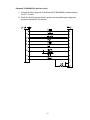
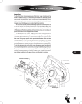
Quick Response Alarm
Version 1.00
Printings
Version 1.00: 01/07/2005
TABLE OF CONTENTS
SPECIFICATIONS ........................................................................................................................ 1
1.0 GENERAL DESCRIPTION .................................................................................................... 2
1.1 Description ................................................................................................................. 2
1.2 Capabilities and Features .......................................................................................... 2
1.3 Operation ................................................................................................................... 2
2.0 INSTALLATION AND SETUP ............................................................................................... 3
2.1 Inspection ................................................................................................................... 3
2.2 Disassembly and Reassembly ................................................................................... 3
2.3 Setup Procedure ........................................................................................................ 3
2.4 Radio Connection ....................................................................................................... 3
2.5 Computer Connection ................................................................................................ 5
2.6 Alarm Input Connections ............................................................................................ 6
2.7 Alarm Output Connections ......................................................................................... 6
2.8 Audio .......................................................................................................................... 6
2.9 Jumper Settings ......................................................................................................... 7
2.10 Quick Response Alarm Programmer........................................................................ 7
3.0 ALIGNMENT .......................................................................................................................... 7
4.0 CIRCUIT DESCRIPTION ....................................................................................................... 7
4.1 Power Supply ............................................................................................................. 7
4.2 Transmit Audio ........................................................................................................... 8
4.3 Receive Audio ............................................................................................................ 8
4.4 PTT ............................................................................................................................ 9
4.5 Inputs ......................................................................................................................... 9
4.6 Outputs ....................................................................................................................... 9
4.7 Programming Cable ................................................................................................... 9
APPENDIX A – RADIO INTERFACES....................................................................................... 10
Kenwood TK-880/980/981 Interface ............................................................................... 10
Kenwood TK-840/940/941 Interface ............................................................................... 12
Uniden SMU 4525KT/SMH 1525DT Interface................................................................. 16
Tekk NT-10/80/90 Interface ............................................................................................ 19
APPENDIX B – EXAMPLE ALARM INPUTS ............................................................................. 20
BRK Electronics Smoke Alarm (Model 4120B) ............................................................... 20
Glass Break Detector ...................................................................................................... 20
PARTS LIST ............................................................................................................................... 21
SCHEMATIC ............................................................................................................................... 24
SPECIFICATIONS
Input Voltage
with PTT relay and for programming
7 to 16 VDC
Input Voltage
without PTT relay
5 to 16 VDC
Standby current @ 13.8 Vdc
30 mA
Maximum current @ 13.8 Vdc
100 mA
Temperature range
0 to +70° C
RX input level
30 mVrms – 1 Vrms
TX output level
30 mVrms – 1 Vrms
DTMF
30 mVrms – 0.8 Vrms
Two tone
range
accuracy
distortion
30 mVrms – 1 Vrms
300 – 4000 Hz
1%
> 3% when f > 500 Hz
> 5% when 300 < f < 500 Hz
Weight
0.86 lb.
Dimensions
7” x 3.5” x 1.5”
1
1.0 GENERAL DESCRIPTION
1.1 Description
The Quick Response Alarm provides programmable notifications from programmable
inputs. Single tones, DTMF tones, and speech notifications can be programmed to
transmit a radio when an input is triggered. There are 12 programmable inputs that can
be triggered by various devices, such as smoke alarms in case of fire, or glass break
detectors in case of intrusion. There are also three outputs on the Quick Response
Alarm, which can be activated and deactivated by DTMF tones received by the
connected radio.
The Quick Response Alarm is designed for use on 150 MHz, 450 MHz, 800 MHz,
shared or dedicated, trunked or conventional radio systems. The Quick Response
Alarm is capable of interfacing with many radio systems including fire and police radios.
If power fails, the battery of the radio or an external UPS can power the circuit for
several hours. If the voltage falls below the operational voltage of the unit, then the unit
will stay in discharged mode until power returns without going into a distressed mode.
This eliminates unnecessary false positives.
1.2 Capabilities and Features
•
•
•
•
•
•
•
•
PC programmable
Non-volatile memory
12 programmable inputs
3 programmable outputs
Single tone, DTMF, and speech encoding
Low power consumption
Broad input voltage range of 7 to 16 VDC (5 to 16 VDC if PTT relay is not used)
Flexible radio interface
1.3 Operation
The Quick Response Alarm provides emergency notifications from programmable
inputs. To avoid false positives, the inputs must remain active for the programmable
debounce time before triggering an alarm. When an alarm is triggered, the Quick
Response Alarm will check the RX and TX indicators to monitor radio traffic. After a
programmable amount of time of no traffic, the Quick Response Alarm will broadcast its
message. The message can consist of single tones, DTMF tones, and speech
(converted from text). The unit will turn the LED off and pulse it on every 4 seconds to
indicate an alarm. Pushing the reset button near the LED will reset the unit. After
pushing the reset button the LED will be on (solid).
If the operational values stored in the Quick Response Alarm are invalid, the LED will
flash quickly. The unit will not monitor any of the inputs in this mode and should be
reprogrammed with valid operational values. When the unit is being programmed, the
LED will flash, indicating that the operational values are being stored in the unit.
2
2.0 INSTALLATION AND SETUP
2.1 Inspection
Please refer to the checklist packed with the Quick Response Alarm in order to become
familiar with the unit and to insure that everything ordered has been received. In the
event a part is missing from the checklist, please call the Customer Services Department
at 1-800-627-4432.
This unit was thoroughly inspected before leaving the factory. If the outer package
appears damaged, please inspect the unit for possible damage immediately. Any dents,
scratches, or marks suggest rough handling in shipping. Please notify the shipper if you
find any indications of mishandling. If there are any concerns about the condition of the
Quick Response Alarm when it is received, please don’t hesitate to call the Customer
Services Department.
2.2 Disassembly and Reassembly
When performing the alignment procedure or making changes to the jumpers on the
Quick Response Alarm, it is necessary to remove the printed circuit board from the case.
This is accomplished by removing the two black screws from the front of the Quick
Response Alarm and removing the front panel. Remove the top cover by sliding it off
the Quick Response Alarm. Since the printed circuit board contains sensitive circuitry,
be sure to take the necessary precautions against static discharge.
To reassemble the Quick Response Alarm, replace the top cover and the front panel
making sure the front and back panels are seated properly with the case. Replace the
two black screws but do not over tighten them.
2.3 Setup Procedure
The first step to install a Quick Response Alarm is to perform a bench test. The purpose
of the bench test is to set up the Quick Response Alarm to operate with the radio to
which it will be connected. Refer to section 2.4 Radio Connection or Appendix A –
Radio Interfaces, if your radio is listed, to determine your radio connection. Connect
the provided serial cable to the computer and to the Quick Response Alarm. Connect
the radio to provide power to the Quick Response Alarm. Then use the QRA
Programmer to program the Quick Response Alarm. Refer to section 2.10 Quick
Response Alarm Programmer for information on editing the settings.
The Quick Response Alarm along with the radio can now be installed. Refer to the
radio’s manual for instructions on installing the radio. The Quick Response Alarm
should be installed in close proximity to the radio.
NOTE: The Quick Response Alarm can key the radio at any time. Because of this the
radio should be connected to an antenna or a dummy load at all times. This will
prevent damage to the radio caused by transmitting without a load.
2.4 Radio Connection
The radio connector, J1, is used to interface the Quick Response Alarm to a radio to
provide the signals required for the Quick Response Alarm to control the radio and send
alarms through the radio system.
3
1. Receive audio pin. Various tones are decoded from the audio present on this pin.
For trunking or conventional systems, this pin should be connected to some point
after the radio’s squelch gate so that the Quick Response Alarm will only receive
audio that is being sent to the radio’s speaker. This will prevent the Quick Response
Alarm from receiving transmissions that are being sent to mobiles with a different ID.
For trunking systems, it is also possible to connect the receive audio pin to some
point before the radio's squelch gate (such as the discriminator output) but only if the
receive indicator pin is connected to a point in the radio that goes active when the
radio is receiving a transmission (audio is being passed to the speaker). This is to
ensure that the Quick Response Alarm does not receive transmissions that are being
sent to mobiles with a different ID.
NOTE: The point in the radio where the receive audio is obtained should not be
affected by the radio's volume control.
2. Transmit audio pin. This pin should be connected to some point in the radio that will
allow the audio on this pin to be transmitted when the Quick Response Alarm
activates the radio’s PTT. The transmit audio pin can be set up as either a low or
high impedance output.
3. Transmit indicator pin. This pin is used by the Quick Response Alarm to determine
when the radio is keyed. It should be connected to some point that goes active when
the radio is keyed (such as the transmit LED). For trunking systems, it could instead
be connected to a point that goes active when the system has been successfully
accessed. The transmit indicator pin can be programmed as either an active high or
active low input or be ignored/disabled.
4. Receive indicator pin. This pin is used by the Quick Response Alarm to determine
when the radio is receiving a transmission. The Quick Response Alarm will not
attempt to key the radio while this pin is in an active state. The receive indicator pin
can be programmed as either an active high or active low input or be
ignored/disabled.
For trunking systems, this pin should be connected to a point in the radio that goes
active when a transmission is being received by the radio but does not go active
when other traffic occurs on the channel (for example, the control line that enables
audio to the radio's speaker). This is to ensure that the Quick Response Alarm does
not receive transmissions that are being sent to mobiles with a different ID.
For conventional systems, this pin should be connected to a point in the radio that
goes active when a carrier is detected by the radio (such as the output of the squelch
detect circuit). This is to ensure that the Quick Response Alarm will not attempt to
transmit while the radio channel is being used by other users.
5. PTT relay normally closed contact.
6. Ground pin. It should be connected to the radio’s ground.
7. No connect.
4
8. Supply power for the Quick Response Alarm. It should be connected to a point in the
radio that will provide DC power to the Quick Response Alarm. It is recommended
that the radio’s power switch control power to the Quick Response Alarm as well.
9. Ground pin. It should be connected to the radio’s ground.
10. PTT output pin. The Quick Response Alarm keys the radio by activating this pin. This
pin should be connected to some point in the radio that will cause the radio to key up
when this pin is activated. The PTT output pin can be programmed as either an
active high or active low output. This pin may be set as the PTT relay normally open
contact by shorting JP1, pins 1-2.
11. Auxiliary PTT relay common contact.
12. Auxiliary PTT relay normally closed contact.
13. Auxiliary PTT relay normally open contact.
14. PTT relay common contact.
15. No connect.
2.5 Computer Connection
A computer must be connected to the Quick Response Alarm in order to program setup
data into it. To connect the computer to the Quick Response Alarm, the modular plug
end of the programming cable should be plugged into the modular jack labeled “SERIAL”
on the front of the Quick Response Alarm. The DB-25 end of the programming cable
should be plugged into the serial port of the computer. If the computer has a DB-9 serial
port, the DB-25 to DB-9 adapter will need to be used.
Quick Response Alarm
J2 – Serial Connector
1 – +5 VDC
2 – Serial In
7 – Serial Out
8 – Ground
Computer
DB – 25
2 – TX
3 – RX
7 – GND
5
2.6 Alarm Input Connections
The alarm connectors, J4, J5, and J6, provide 12 inputs to the Quick Response Alarm.
The Quick Response Alarm uses these inputs to determine the state of external devices.
Alarms can be generated by the Quick Response Alarm when the states of the external
devices change to the active state. The inputs are de-bounced and any new input level
must be held for a programmable amount of time to be recognized. The inputs can be
programmed as either active high or active low. The connections on J4, J5, and J6
alternate between inputs and ground.
Quick Response Alarm Inputs
J4
J5
1 – Input 1
1 – Input 5
2 – Ground
2 – Ground
3 – Input 2
3 – Input 6
4 – Ground
4 – Ground
5 – Input 3
5 – Input 7
6 – Ground
6 – Ground
7 – Input 4
7 – Input 8
8 – Ground
8 – Ground
J6
1 – Input 9
2 – Ground
3 – Input 10
4 – Ground
5 – Input 11
6 – Ground
7 – Input 12
8 – Ground
2.7 Alarm Output Connections
The external output connector, J7, provides three external outputs to allow control of
external devices by DTMF tones. The connections on J7 alternate between outputs and
ground. The outputs are open collectors without a pull-up.
Quick Response Alarm Outputs
J7
1 – Output 1
2 – Ground
3 – Output 2
4 – Ground
5 – Output 3
6 – Ground
2.8 Audio
The Quick Response Alarm has 12 programmable audible alarms that can consist of
single tones, DTMF burst tones, DTMF timed tones, and speech assigned to each of the
alarm inputs. Each alarm component is programmable for frequency, message,
duration, timing, and order.
6
2.9 Jumper Settings
JP1 – This jumper selects whether or not to use the relay for PTT.
1-2: The relay will be used for PTT.
2-3: The PTT output pin will be open collector, and the relay will not be used.
JP2 – Audio High Impedance Jumper
Open for high impedance audio output.
JP3 – This jumper determines if the received audio will be de-emphasized.
1-2: The received audio will not be de-emphasized.
2-3: The received audio will be de-emphasized.
JP4 – RX Detect Jumper
Short to enable the RX detection circuit from the RX input line.
2.10 Quick Response Alarm Programmer
The QRA Programmer allows parameters to be changed to interface with the radio and
control the Quick Response Alarm.
The input settings can be found under the three input tabs. The output settings can be
found under the Configuration tab, along with the radio interface settings. A convenient
interface can be used to change the settings and each parameter is described in the
help script.
3.0 ALIGNMENT
The Quick Response Alarm should require minimal adjustment. If an adjustment to the
main transmit audio is needed, R25 can be adjusted. If a single signal source is out of
alignment, the gain for that source can be adjusted independently. Adjust R19 for single
tones, R20 for DTMF tones, and R21 for speech by turning it clockwise for more gain or
counterclockwise for less gain.
The gain of the DTMF decoding circuit is set at the factory to unity gain. If adjustments
to the gain are required, monitor TP3 while adjusting R60. The receive audio at TP3
should be in the range of 27.5 - 489 mVRMS with no clipping of the input signal.
4.0 CIRCUIT DESCRIPTION
4.1 Power Supply
The Quick Response is powered from a 7 to 16 VDC (5 to 16 VDC if relay is not used)
supply across pins 8 and 9 on the radio connector (J1). The supply is fed into voltage
regulators U1 and U8. U1 is a 3.3 VDC regulator that provides power for most of the
board. U8 is a 5 VDC regulator that provides power for serial communication to program
the Quick Response and the PTT relay, if used.
7
4.2 Transmit Audio
The Quick Response TX audio and TX indicator lines are pins 2 and 3 respectively on
the radio connector (J1). The TX audio can be adjusted with R25, which is the feed
back for the summing operation of the audio output sources. Each audio source has an
adjustable impedance to control the output.
a. Text to Speech
Spoken messages are generated by the Text-to-Speech IC (U7). The Text-toSpeech IC receives text strings from the microcontroller (U4) and converts them into
speech. The Text-to-Speech output is adjusted with R21.
b. DTMF Tones
DTMF tones are generated by the integrated DTMF transceiver (U6). DTMF Tone
output can be adjusted with R20.
c. Single Tones
Single tones are generated by the active filter (U2) with signals provided by the
microcontroller (U4). The microcontroller sends the active filter the frequency and a
clock of 200 times the frequency, to set the corner frequency. The resulting output is
a sinusoid at the desired frequency. Single Tone output can be adjusted with R19.
4.3 Receive Audio
The RX audio and RX indicator lines are pins 1 and 4, respectively, on the radio
connector (J1). The jumper JP3 can also be set to 1-2 and the RX audio will not be deemphasized or set to 2-3 and the RX audio will be de-emphasized.
a. DTMF Decode
DTMF tones are detected by the integrated DTMF transceiver (U6) and sent to the
microcontroller (U4). The input level can be adjusted at R60.
b.
RX Detect
RX detect is driven by the op-amp U11A and isolated by the op-amp U11B. If the
interfaced unit does not have a RX indicator, JP4 can be shorted to use the RX
detect circuit.
8
4.4 PTT
The PTT output can be set to either a relayed output by shorting pins 1-2 on JP1, or an
open collector output by shorting pins 2-3 on JP1. When the relay is being used, the
active state of the PTT output should be programmed as active low, which will energize
the relay on PTT. The common, normally closed, and normally open lines for the relay
are pins 14, 5, and 10 on the radio connector (J1), respectively. There are also auxiliary
connections for the relay, where the common, normally closed, and normally open lines
are pins 11, 13, and 12 on the radio connector.
When PTT output is set as an open collector output, pin 10 on the radio connector (J1)
is set to the active state on PTT. External pull-ups may be required for active high
configurations.
4.5 Inputs
The inputs can be programmed as active high or active low. The inputs are fed into an
IO expander (U5) where the microcontroller can read their state.
4.6 Outputs
The outputs are open collector without pull-ups. The outputs come from the IO
expander (U5) which is controlled by the microcontroller (U4).
4.7 Programming Cable
The programming cable is used for programming the desired configuration into the Quick
Response Alarm. One end of the cable is an eight position modular connector that plugs
into J2 on the Quick Response Alarm. The other end is a DB-25 connector that
connects to the serial port of the computer. Inside the housing of the DB25 connector is
a TTL to RS232 converter. Four wires are used between the Quick Response Alarm
and the converter. These are 5 VDC, ground, RX data, and TX data. If the computer
has a DB-9 serial port the DB-25 to DB-9 adapter will need to be used.
9
APPENDIX A – RADIO INTERFACES
This appendix contains instructions for interfacing the Quick Response Alarm to selected
radios. If modifications to the radio are required the steps necessary are given.
Kenwood TK-880/980/981 Interface
The following items are included in the Kenwood TK-880/980/981 cable interface kit:
1. Kenwood TK-880/980/981 interface cable assembly.
2. Instruction sheet.
The following steps outline the procedure for interfacing the Kenwood TK-880/980/981
radio to the Quick Response Alarm.
1. The enclosed interface cable needs to have one pin installed in the appropriate
location. This cable can be used for a variety of applications. For the Quick
Response Alarm the loose pin can be inserted into Pin 15 of the molex
connector.
2. Set the Quick Response Alarm up for a bench test and use the QRA
Programmer to set the following operating constants to the indicated value:
Transmit indicator active:
Receive indicator active:
PTT output active:
Low
Low
Low
3. Configure the following jumpers as indicated:
JP1
JP2
JP3
JP4
2-3
Removed
2-3
Removed
4. Program the Kenwood TK-880/980/981 Optional Features for the following:
Com 2
Logic Signaling :
Squelch Logic Type
Squelch Logic Signal
Access Logic Type
Access Logic Signal
(AuxHook / PTT)
Active Low
TOR
Active Low
Continuous
5. Install the Accessory Cable KCT-19 in the Kenwood TK-880/980/981.
Insert the cable connectors in CN1, CN2, and CN3.
** R17 in the Kenwood TK-880/980/981 may need to be removed if the radio is an
“early” version. (This needs to be done if the external PTT does not work.)
6. Connect the DB-15 end of the Kenwood TK-880/980/981 interface cable to the
DB-15 connector on the back of the Quick Response Alarm.
10
Kenwood TK-880/980/981 Interface (cont.)
7. Connect the Molex plug end of the Kenwood TK-880/980/981 interface cable to
the KCT-19 cable.
8. Check the Quick Response Alarm’s audio levels by performing the alignment
procedure described in this manual.
11
Kenwood TK-840/940/941 Interface
The following items are included in the Kenwood TK-840/940/941 interface kit:
1.
2.
3.
4.
TK-840/940/941 interface cable assembly.
3 short pieces of wire.
3 short pieces of heat shrink tubing.
Instruction sheet.
The following steps outline the procedure for interfacing the Kenwood TK-840/940/941
radio to the Quick Response Alarm. The Kenwood TK-840/940/941 radio can operate in
either trunking or conventional mode but the interface will depend upon the mode
selected as detailed in the following steps.
1. Set the Quick Response Alarm up for a bench test and use the QRA
Programmer to set the following operating constants to the indicated value:
Trunking
Transmit indicator active:
Receive indicator active:
PTT output active:
Low
High
Low
Conventional
Transmit indicator active:
Receive indicator active:
PTT output active:
High
High
Low
2. Configure the following jumpers as indicated:
Trunking
JP1 2-3
JP2 Installed
JP3 2-3
JP4 Removed
Conventional
JP1 2-3
JP2 Installed
JP3 1-2
JP4 Removed
3. Install the KCT-19 accessory connection cable into the TK-840/940/941 radio by
following the instructions in the TK-840/940/941 service manual. The cable
connectors should be connected to the TX-RX unit as follows:
Cable
B
C
D
E
TX-RX unit
CN4
No connection
CN1
CN2
4. Place the speaker and speaker holder off to the side and remove the shield cover
located beneath the speaker.
5. Locate capacitor C93 and solder a piece of wire to the side of C93 that is
connected to Q20 as shown in the following diagram.
12
Kenwood TK-840/940/941 Interface (cont.)
6. Trunking only: Locate capacitor C92 and solder a piece of wire to the side of
C92 that is connected to the hole labeled "AC" as shown in the following
diagram.
Conventional only: Locate capacitor C75 and solder a piece of wire to the side
of C75 that is connected to pin 7 of IC9 as shown in the following diagram.
7. Cut the brown wire going to pin 1 of connector B (the larger 3 position connector)
on the KCT-19 cable. Place a piece of heat shrink tubing on this wire and solder
this wire to the wire that was soldered to C93.
8. Trunking only: Cut the gray wire going to pin 8 of connector D (the 8 position
connector) on the KCT-19 cable. Place a piece of heat shrink tubing on this wire
and solder this wire to the wire that was soldered to C92.
Conventional only: Cut the brown wire going to pin 1 of connector D (the 8
position connector) on the KCT-19 cable. Place a piece of heat shrink tubing on
this wire and solder this wire to the wire that was soldered to C75.
9. Move the heat shrink tubing into place and shrink it.
10. Replace the shield cover making sure the wires pass through slots in the cover
without being pinched.
11. Conventional only: On the bottom side of the radio, locate transistor Q12 and
solder a piece of wire to Q12 as indicated in the following diagram. Pass this wire
through a hole in the PC board to the top side of the radio.
13
Kenwood TK-840/940/941 Interface (cont.)
12. Conventional only: Cut the white wire going to pin 1 of connector E (the smaller
3 position connector) on the KCT-19 cable. Place a piece of heat shrink tubing on
this wire and solder this wire to the wire that was soldered to Q12 in the previous
step. Move the heat shrink tubing into place and shrink it.
13. Replace the speaker holder, speaker, and the radio covers.
14. Connect the DB-15 end of the TK-840/940/941 interface cable to the DB-15
connector on the back of the Quick Response Alarm.
15. Connect the Molex plug end of the TK-840/940/941 interface cable to the KCT-19
cable.
16. Check the Quick Response Alarm’s audio levels by performing the alignment
procedure described in this manual.
14
Kenwood TK-840/940/941 Interface (cont.)
TK-840/940/941 Interface Cable
15
Uniden SMU 4525KT/SMH 1525DT Interface
The following items are included in the Uniden SMU 4525KT/SMH 1525DT interface kit:
1.
2.
3.
4.
5.
SMU 4525KT/SMH 1525DT interface cable assembly.
7 lengths of wire with Molex pins.
2 short pieces of heat shrink tubing.
2M ohm resistor.
Instruction sheet.
The following steps outline the procedure for interfacing the Uniden SMU 4525KT/SMH
1525DT to the Quick Response Alarm.
1. Set the Quick Response Alarm up for a bench test and use the QRA
Programmer to set the following operating constants to the indicated value:
Transmit indicator active:
Receive indicator active:
PTT output active:
High
Low
Low
2. Configure the following jumpers as indicated:
JP1
JP2
JP3
JP4
2-3
Removed
2-3
Removed
3. On the Quick Response Alarm board, remove JP2 and replace it with a 2M ohm
resistor. Remove R49 and remove C25.
4. Remove top and bottom covers of the radio and un-snap the faceplate from the
main body of the radio.
5. Remove the radio’s power connector from the rear of the radio for easier access
to the accessory jack. Re-install the power connector when all connections to
the accessory jack are complete.
6. Install the wires with Molex pins into the accessory connector from the inside of
the radio as follows:
Pin #
4
5
6
7
8
9
10
Wire
Red
Blue
Brown
Orange
Yellow
White
Gray
7. Locate the wire connected to pin 4 of J401 which is labeled as “MIC”. Cut this
wire at the center of its length.
16
Uniden SMU 4525KT/SMH 1525DT Interface (cont.)
8. Place a piece of heat shrink tubing onto both the yellow and gray wires that were
installed into the accessory connector.
9. Solder the yellow wire to the side of the cut wire that goes to the main board and
solder the gray wire to the side of the cut wire that goes to the faceplate.
10. Move the heat shrink tubing into place on both wires and shrink it.
11. Connect the remaining wires that were installed into the accessory connector to
the following points in the radio as shown in the diagram that follows:
Red
Blue
Brown
Orange
White
positive side of C405 (on main board)
J603 pin 3
WA603 pin 1
J601 pin 3
J604 pin 3
12. Position the wires through the slot with the existing wires and replace the
faceplate and the radio covers.
13. Connect the Molex plug end of the SMU 4525KT/SMH 1525DT interface cable to
the 12 pin accessory jack on the back of the radio.
14. Connect the DB-15 end of the SMU 4525KT/SMH 1525DT interface cable to the
DB-15 connector on the back of the Quick Response Alarm.
15. Check the Quick Response Alarm’s audio levels by performing the alignment
procedure described in this manual.
17
Uniden SMU 4525KT/SMH 1525DT Interface (cont.)
SMU 4525KT/SMH 1525DT Interface Cable
18
Tekk NT-10/80/90 Interface
The following items are included in the Tekk NT-10/80/90 interface kit:
1. NT-10/80/90 interface cable assembly.
2. 2 short pieces of heat shrink tubing
3. Instruction sheet.
The following procedure interfaces the Tekk NT-10/80/90 with the Quick Response
Alarm.
1. Setup and program the Quick Response Alarm EEPROM
2. Configure the following jumpers as indicated.
3. Configure the following jumpers as indicated:
JP1
JP2
JP3
JP4
1-2
Removed
1-2
Inserted
3. Adjust audio gains. Set line to TX gain (R25) to about 20%.
4. Remove the battery and solder the Quick Response power connector on the
NT-10/80/90 interface cable to the correct battery connectors on the Tekk
NT-10/80/90.
5. Connect the wall charger cable to the charging connector on the NT-10/80/90
interface cable. Cut the end connector off of the NT-10/80/90’s wall charger
cable. Separate and strip the two wires. Place a short piece of the heat
shrink tubing over each of the wires. Solder the wires from the wall charger
to the NT-10/80/90 interface cables charging leads. The wall charger’s
positive lead will be unmarked. The negative lead will have a white dashed
line running the length of it.
6. Replace the battery.
7. Connect power to the wall charger.
8. Connect the NT-10/80/90 interface to the Quick Response Alarm.
9. Connect the NT-10/80/90 interface cable to the options jack on the radio.
19
APPENDIX B – EXAMPLE ALARM INPUTS
BRK Electronics Smoke Alarm (Model 4120B)
The BRK Electronics smoke alarm
Glass Break Detector
Glass break detector.
20
PARTS LIST
Quick Response Alarm
101-QRA-REVB
Item
Reference
Description
Part No.
Qty.
1
C1,4,5,6,8,9,11,12,13,15,18, CAP, .1UF X7R 16V
19,20,22,23,44,45,47,48,51,
52,53,55
375-2104R
23
2
3
4
5
6
7
C2,14
CAP, A ELEC 47UF 6.3
381-0470R
C3
CAP, A ELEC 47UF 16V 381-2470R
C7
CAP, 47000PF X7R 25V 375-3473R
C10
CAP, A ELEC 4.7UF 25
381-3475R
C16,17
CAP, 16PF C0G 100V
375-7160R
C21,24,25,26,27,28,29,30,3 CAP, .01UF X7R 10%50 375-5103R
1,
32,33,34,35,36,37,38,39,42,
43,46,49,50
C40
CAP, .33UF X5R 16V
375-2334R
C41,54
CAP, 2.2UF X5R 6.3V
375-0225R
C56
CAP MONO .1UF 5% 50V 362-0001
D1,4,5,6,7,8,9,10,11,12,13,1 DIODE, 4148 SMT
110-0018R
4, 15,16,17
D2
DIODE, MMBZ5226 SMT 110-2102R
D3
LED, T-1 3/4 GRN
112-0002
D3
DIODE, 4148 SMT
110-0018R
D18,19
LED GUIDE R/A
113-0101
F1
FUSE,.75A 13.2V REST
290-1001
J1
CONN DB15 FEM R/A PC 231-0031
J2
JACK UNIVRSL 8TO6 OB 231-0007
J3
NOT INSTALLED
000-0002
J4,6
HEADER 8POS RA
231-1631
J5
HEADER 8POS RA OPEN 231-1632
J7
HEADER 6POS RA
231-1630
J1
HEX NUT 4-40
199-0010
J1
WASHER, STAR #4
199-2001
J1
SCREW, 4-40X3/8 PHLP 199-3056
JP1,3
CONN 3 POS GOLD POST 231-1003
JP2,4
CONN 2 POS GOLD POST 231-1002
JP1,2,3,4
SHORTING JUMPER
234-0046
K1
RELAY, TQ2SA-5V
700-1000
L1
FERRITE, 150 OHM 800 306-2001R
Q1,2,3,4,5,6,7,8,9,10,11,12, TRNSTR, MMUN2211LT1 180-0040
13,14,15,16,17,18,19
R1,17
RES, 39K 5% 1/10W
323-1393R
R2,4
RES, 390K 5% 1/10W
323-1394R
R3,14,57
RES, 100K 5% 1/10W
323-1104R
R5,6
RES, 0 5% 1/10W
323-0000R
2
1
1
1
2
22
8
9
10
11
12
13
14
15
16
17
18
19
20
21
22
23
24
25
26
27
28
29
30
31
32
33
34
35
21
1
2
1
15
1
1
1
2
1
1
1
1
2
1
1
1
1
1
2
2
4
1
1
19
2
2
3
2
36
37
38
39
40
41
42
43
44
45
46
47
48
49
50
51
52
53
54
55
56
57
58
59
60
61
62
323-1103R
R7,13,18,22,23,26,27,28,29, RES, 10K 5% 1/10W
30,31,32,33,34,35,36,37,38,
39,40,41,42,43,44,45,46,47,
48,49,53,54,55,56,58,59,61,
62,63,64,65,66,67,68,73
R8,9,11,12,15,69,70
RES, 33K 5% 1/10W
323-1333R
R16
RES, 18K 5% 1/10W
323-1180R
R10
RES, 4.7K 5% 1/10W
323-1472R
R19,20,21,25
POT 100K 1 Turn
351-1104
R24
RES, 240 5% 1/10W
323-1241R
R50,51
RES, 100 1% 1/16W
322-1000R
R52
RES, 470 5% 1/10W
323-1471R
R60
POT 50K 1 Turn
351-0010
R71
RES, 50K 5% 1/10W
323-1510R
R72
RES, 1K 5% 1/10W
323-1102R
R74
RES, 1M 1% 1/16W
322-1004R
S1
MOM SWITCH RA 3.85MM 611-0057
TP1,2,3,4
TEST POINT PC MOUNT 200-0013
U1
IC, LM1117MP-3.3
131-5006
U2
IC, MAX7404
131-1082
U3
IC, 25AA320
131-1079
U4
IC, MICRO P89LPC932
131-1065
U5
IC, MAX7301
131-1084
U6
IC, MT88L89
131-1083
U7
IC, WTS701
131-1085
U8
IC, LM78L05ACM
131-1080
U9,11
IC, LMV324
131-1081
U10
IC, 74HC125
131-1054
X1
CRYS 24.576MHZ LOPRO 305-0107
X2
CR 3.579545MHZ LOPRO 305-0106
Quick Response PCB
900-0302
QUICK RESPONSE ALARM CABINET
103-0277
Item
1
2
3
4
5
Description
Part No.
S/N LBL IDA PRODUCT
NUT, PEM 6-32 FLUSH
CAB, QUICK ALARM
FACEPLATE, QK ALARM
BACKPLATE, QA SCREEN
199-6009
200-0056
900-5065
900-5066S
900-5067S
Qty.
1
4
1
1
1
QUICK RESPONSE ALARM BRACKET KIT
103-5025
Item
1
2
3
4
Description
Part No.
SCW, #10 X 3/4 SHEET MET.
SCW, #6-32 X 3/16 PHILLIPS
WASHER, STAR #6
BRACKET, TRAKIT ANOD.
199-1009
199-3068
199-2002
900-5025A
22
Qty.
4
4
4
1
44
7
1
1
4
1
2
1
1
1
1
1
1
4
1
1
1
1
1
1
1
1
2
1
1
1
1
QUICK RESPONSE ALARM PROGRAMMING CABLE
431-RBC-003
Item
1
2
3
4
5
6
7
Reference
Description
Part No.
Qty.
C1,2,3,4
J1
J2
U1
10uF TANT CAP
IDC PC MOUNT PIN
DB25 W/FEMALE PIN
MAX232, IC
DB25 HOOD COVER
CABLE ASSEMBLY
PROGRAMMING CABLE PCB
390-9106
231-0041
231-0022
130-0235
231-0046
800-2027
900-0215
4
4
1
1
1
1
1
23
SCHEMATIC
(Insert schematic here.)
24