1
®
Part No. 17-00590-3
Published August 1996
EDGE ROUTER MODULE
INSTALLATION GUIDE
FOR ETHERNET
3Com Corporation ■ 5400 Bayfront Plaza
California ■ 95052-8145
■
Santa Clara,
©3Com Corporation, 1996. All rights reserved. No part of this
documentation may be reproduced in any form or by any means or
used to make any derivative work (such as translation,
transformation, or adaptation) without permission from
3Com Corporation.
3Com Corporation reserves the right to revise this documentation,
and to make changes in content from time to time, without
obligation on the part of 3Com Corporation to provide notification of
such revision or change.
3Com Corporation provides this documentation without warranty
of any kind, either implied or expressed, including, but not
limited to, the implied warranties of merchantability and fitness
for a particular purpose. 3Com may make improvements or
changes in the products and the programs described in this
documentation at any time.
UNITED STATES GOVERNMENT LEGENDS:
If you are a United States government agency, then this
documentation and the software described herein are provided to
you subject to the following restricted rights:
Canadian Emissions Requirements
This Class A digital apparatus meets all requirements of the Canadian
Interference-Causing Equipment Regulations.
Cet appareil numérique de la classe A respecte toutes les exigences
du Règlement sur le matériel brouilleur du Canada.
EMC Directive Compliance
This equipment was tested and conforms to the Council
Directive 89/336/EEC for electromagnetic compatibility. Conformity
with this directive is based upon compliance with the following
harmonized standards:
EN 55022 – Limits and Methods of Measurement of
Radio Interference
EN 50082-1 – Electromagnetic Compatibility Generic Immunity
Standard: Residential, Commercial, and Light Industry
Warning: This is a Class A product. In a domestic environment, this
product may cause radio interference, in which case you may be
required to take adequate measures.
Compliance with this directive depends on the use of shielded
cables. [optional shielded cables statement]
VCCI Class 1 Compliance
For units of the Department of Defense:
Restricted Rights Legend: Use, duplication, or disclosure by the
Government is subject to restrictions as set forth in subparagraph (c)
(1) (ii) of the Restricted Rights in Technical Data and Computer
Software clause at 48 C.F.R. 52.227-7013. 3Com Corporation.
For civilian agencies:
Restricted Rights Legend: Use, reproduction, or disclosure is subject to
restrictions set forth in subparagraphs (a) through (d) of the
Commercial Computer Software - Restricted Rights clause at
48 C.F.R. 52.227-19 and the limitations set forth in
3Com Corporation’s standard commercial agreement for the
software. Unpublished rights reserved under the copyright laws of
the United States.
This equipment is in the 1st Class category (information equipment
to be used in commercial or industrial areas) and conforms to the
standards set by the Voluntary Control Council for Interference by
Information Technology Equipment aimed at preventing radio
interference in commercial or industrial areas.
If there is any software on removable media described in this
documentation, it is furnished under a license agreement included
with the product as a separate document, in the hard-copy
documentation, or on the removable media in a directory file
named LICENSE.TXT. If you are unable to locate a copy, please
contact 3Com and a copy will be provided to you.
Read the instructions for correct handling.
Federal Communications Commission Notice
This equipment was tested and found to comply with the limits for a
Class A digital device, pursuant to Part 15 of the FCC Rules. These
limits are designed to provide reasonable protection against harmful
interference when the equipment is operated in a commercial
environment. This equipment generates, uses, and can radiate radio
frequency energy and, if not installed and used in accordance with
the instruction manual, may cause harmful interference to radio
communications. Operation of this equipment in a residential area is
likely to cause harmful interference, in which case you must correct
the interference at your own expense.
ii
Consequently, when the equipment is used in a residential area or in
an adjacent area, radio interference may be caused to radio and TV
receivers, and so on.
Fiber Cable Classification Notice
Use this equipment only with fiber cable classified by Underwriters
Laboratories as to fire and smoke characteristics in accordance with
Section 770-2(b) and Section 725-2(b) of the National Electrical Code.
UK General Approval Statement
The ONcore Switching Hub, ONline System Concentrator, and
ONsemble StackSystem Hub are manufactured to the International
Safety Standard EN 60950 and are approved in the UK under the
General Approval Number NS/G/12345/J/100003 for indirect
connection to the public telecommunication network.
Trademarks
Unless otherwise indicated, 3Com registered trademarks are
registered in the United States and may or may not be registered in
other countries.
3Com, Boundary Routing, CardBoard, CardFacts, EtherDisk, EtherLink,
EtherLink II, LANplex, LANsentry, LinkBuilder, NETBuilder,
NETBuilder II, NetFacts, ONcore, ONsemble, ORnet, Parallel Tasking,
SmartAgent, TokenLink, Transcend, TriChannel, and ViewBuilder are
registered trademarks of 3Com Corporation.
3Com Laser Library, 3Com OpenHub, 3TECH, FDDILink, FMS,
MultiProbe, NetProbe, ONdemand, ONline, PowerRing, StackJack,
StackWay, and SwitchCentral are trademarks of 3Com Corporation.
3ComFacts and Ask3Com are service marks of 3Com Corporation.
The 3Com Multichannel Architecture Communications System is
registered under U.S. Patent Number 5,301,303.
AT&T is a registered trademark of American Telephone and Telegraph
Company.
AppleTalk is a registered trademark of Apple Computer, Inc.
Sun Microsystems, Inc.
SPARCstation and SPARCompiler are licensed exclusively to Sun
Microsystems, Inc.
OPEN LOOK is a registered trademark of UNIX System Laboratories,
Inc.
UNIX is a registered trademark in the United States and other
countries, licensed exclusively through X/Open Company, Ltd.
Xerox is a registered trademark of Xerox Corporation.
Xe rox N et wo r k Sys tem, a nd X N S a re tr a de ma r ks o f Xe rox
Corporation.
Other brand and product names may be registered trademarks or
trademarks of their respective holders.
Guide written by John Doherty. Edited by Jill Angel. Production by
Tracey Taylor.
Apollo and Apollo Domain are registered trademarks of Apollo
Computer, Inc.
Banyan and VINES are registered trademarks of Banyan Systems, Inc.
Cisco and Cisco Systems are registered trademarks of Cisco Systems,
Inc.
AGS+, ASM, IGRP, Internetworking Operating System, IOS, MGS, and
UniverCD are trademarks of Cisco Systems, Inc.
CompuServe is a registered trademark of CompuServe, Inc.
ProComm is a registered trademark of DATASTORM TECHNOLOGIES,
INC.
DATASTORM is a trademark of DATASTORM TECHNOLOGIES, INC.
DEC, DECnet, DELNI, POLYCENTER, VAX, VT100, VT220, and the Digital
logo are trademarks of Digital Equipment Corporation.
Hayes is a registered trademark of Hayes Microcomputer Products.
OpenView is a registered trademark of Hewlett-Packard Company.
Intel is a registered trademark of Intel Corporation.
AIX, IBM, and NetView are registered trademarks of International
Business Machines Corporation.
Microsoft, MS-DOS, and Windows are registered trademarks of
Microsoft Corp.
Motorola is a registered trademark of Motorola Corporation.
V30 is a trademark of NEC Corporation.
NetWare and Novell are registered trademarks of Novell,
Incorporated.
IPX is a trademark of Novell, Incorporated.
OSF and OSF/Motif are registered trademarks of Open Software
Foundation, Inc.
Retix is a registered trademark of Retix.
ROUTERXchange is a trademark of Retix.
Solaris, SPARCengine, Sun, Sun Microsystems, and SunSoft are
registered trademarks of Sun Microsystems, Inc.
ONC, OpenWindows, SunNet Manager, and SunOS are trademarks of
iii
CONTENTS
ABOUT THIS GUIDE
Introduction 9
Audience 9
How to Use This Guide 9
Conventions 10
Related Documents 12
3Com Documents 12
Cisco Documents 13
Reference Documents 13
1
INTRODUCTION
Product Overview 1-1
Edge Router Module Operation 1-1
Edge Router Module Architecture 1-3
Edge Router Module Features 1-5
Software Options 1-5
Topology Switching 1-7
Network Reliability 1-7
IOS Router Software Updates 1-8
Memory Upgrades 1-9
2
INSTALLING THE EDGE ROUTER MODULE
Installation Flowchart 2-2
Precautionary Procedures 2-3
Quick Installation 2-3
Quick Installation for Unmanaged Hubs 2-4
Quick Installation for Managed Hubs 2-5
Unpacking Procedures 2-6
Verifying Jumper Plug Positions 2-7
v
Configuring DIP Switches 2-8
Configuring the ONline Carrier DIP Switches 2-8
Selecting a Network 2-9
Isolating the ONline Edge Router Module 2-9
Configuring the ONcore Carrier DIP Switches 2-9
Enabling or Disabling NVRAM Configuration 2-10
Selecting a Network 2-11
Installing the ONline Edge Router Module 2-12
Installing the ONcore Edge Router Module 2-13
3
CONFIGURING THE EDGE ROUTER MODULE
Managed Configuration Overview 3-2
3Com Management Modules 3-2
Using Management Commands 3-2
Using ONdemand NCS 3-3
Carrier Configuration Tasks 3-3
Attaching a Management Terminal 3-3
Configuring the Carrier in a Managed ONline Hub 3-4
Selecting a Network 3-4
Saving the Configuration 3-4
Configuring the Carrier in a Managed ONcore Hub 3-5
ONcore Carrier Configuration Sources 3-5
DMM Settings 3-5
Carrier NVRAM Settings 3-6
Carrier DIP Switch Settings 3-6
Carrier Default Settings 3-6
Hot Swapping an ONcore Module 3-7
Determining the Configuration Source 3-8
Selecting a Network 3-8
Saving the Configuration 3-9
Configuring the Edge Router Engine 3-9
Attaching a Terminal to the Console Port 3-9
Using the Terminal to Configure the Edge Router Engine
vi
3-11
4
MONITORING EDGE ROUTER MODULE OPERATION
Monitoring Edge Router Module Operation 4-1
Showing Module Configuration and Status 4-3
Using the SHOW MODULE Command 4-4
Using the SHOW PORT Command 4-6
5
TROUBLESHOOTING
Troubleshooting Startup Problems 5-2
Troubleshooting Router-Specific Problems 5-2
Troubleshooting Mailbox Interface Problems 5-2
Troubleshooting 3Com Carrier Problems 5-2
Troubleshooting Network Connectivity Problems 5-3
Troubleshooting WAN Connectivity Problems 5-4
Correcting Operating Malfunctions 5-5
A
SPECIFICATIONS
General Specifications A-2
Electrical Specifications A-2
Environmental Specifications A-3
Mechanical Specifications A-3
Hub Capacities A-4
ONline Hub Capacities A-4
ONcore Hub Capacities A-4
Cable Pinouts A-5
Console Port Pinouts A-6
DTE Console Port A-6
Mini-DIN to DB-25 Modem Cable A-7
Auxiliary Port Pinouts A-8
Mini-DIN to DB-25 Modem Cable A-8
DB-25 Null Modem Cable A-9
Serial Port Pinouts A-9
EIA-530 DTE Synchronous Serial Cable Pinouts A-10
RS-232 DTE and DCE Serial Cable Pinouts A-11
RS-449 DTE and DCE Serial Cable Pinouts A-12
V.35 DTE and DCE Serial Cable Pinouts A-13
X.21 DTE and DCE Serial Cable Pinouts A-14
vii
B
TECHNICAL SUPPORT
Online Technical Services B-1
3Com Bulletin Board Service B-1
Access by Analog Modem B-2
Access by Digital Modem B-2
World Wide Web Site B-3
3ComForum on CompuServe B-3
3ComFacts Automated Fax Service B-3
Support From Your Network Supplier B-4
Support From 3Com Corporation B-5
Returning Products for Repair B-5
Accessing the 3Com ISD MIB B-6
Contacting 3Com ISD Technical Publications
INDEX
LIMITED WARRANTY
viii
B-6
ABOUT THIS GUIDE
Introduction
This guide describes how to install and configure a 3Com® ONline™ or
ONcore® Edge Router module into the 3Com ONline System Concentrator
or ONcore Switching Hub. In addition, this guide provides troubleshooting
suggestions in case a problem arises with the module.
If the information in the release notes shipped with your product differs from
the information in this guide, follow the release note instructions.
Audience
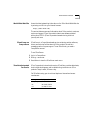
How to Use This
Guide
This guide is intended for the following people at your site:
■
Network manager or administrator
■
Trained hardware installer or service personnel
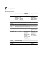
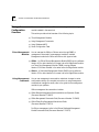
Table 1 shows the location of specific information.
Table 1 How to Use This Guide
If you are looking for:
Turn to:
General information about the Edge Router module
Chapter 1
Description of the module architecture
Typical applications of the Edge Router module
Features of the Edge Router module
An overview of the installation and configuration process
Chapter 2
Procedures for unpacking the Edge Router module
Procedures for preparing to install the Edge Router module
Procedures for installing the Edge Router module
An overview of the managed configuration process
Procedures for attaching a management terminal
Procedures for configuring Edge Router carrier parameters
Chapter 3
10
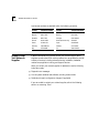
ABOUT THIS GUIDE
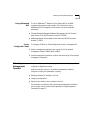
Table 1 How to Use This Guide (continued)
Procedures for configuring Edge Router engine parameters
Chapter 3
Information for monitoring Edge Router module LEDs
Chapter 4
Procedures for displaying module configuration and status
Conventions
Information on troubleshooting the Edge Router module
Chapter 5
Information not covered in the rest of the guide
Appendixes A-B
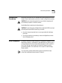
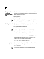
Table 2 and Table 3 list conventions used throughout this guide.
Table 2 Graphic Conventions
Icon
Type
Description
Information Note Information notes call attention to important features or
instructions.
Caution
Cautions alert you to personal safety risk, system
damage, or loss of data.
Warning
Warnings alert you to the risk of severe personal injury.
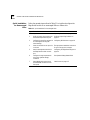
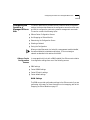
Table 3 Text Conventions
Convention
Description
“Enter” vs. “Type”
When the word “enter” is used in this guide, it means type
something, then press the Return or Enter key. Do not
press the Return or Enter key when an instruction simply
says “type.”
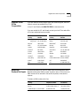
Conventions
11
Table 3 Text Conventions (continued)
Convention
Description
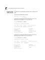
“Syntax” vs. “Command”
When the word “syntax” is used in this guide, it indicates
that the general form of a command syntax is provided.
You must evaluate the syntax and supply the appropriate
port, path, value, address, or string. For example:
Enable RIPIP by using the following syntax:
SETDefault !<port> -RIPIP CONTrol =
Listen
In this example, you must supply a port number for
!<port>.
When the word “command” is used in this guide, it
indicates that all variables in the command have been
supplied and you can enter the command as shown in
text. For example:
Remove the IP address by entering the following
command:
SETDefault !0 -IP NETaddr = 0.0.0.0
For consistency and clarity, the full-form syntax (upper- and
lowercase letters) is provided. However, you can enter the
abbreviated form of a command by typing only the uppercase
portion and supplying the appropriate port, path, address,
value, and so on. You can enter the command in either upperor lowercase letters at the prompt.
Text represented as
screen display
This typeface is used to represent displays that
appear on your terminal screen. For example:
NetLogin:
Text represented as
commands
This typeface is used to represent commands that
you enter. For example:
SETDefault !0 -IP NETaddr = 0.0.0.0
Keys
When specific keys are referred to in the text, they are
called out by their labels, such as “the Return key” or “the
Escape key,” or they may be shown as [Return] or [Esc].
If two or more keys are to be pressed simultaneously, the
keys are linked with a plus sign (+). For example:
Press [Ctrl]+[Alt]+[Del].
Italics
Italics are used to denote new terms or emphasis.
12
ABOUT THIS GUIDE
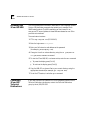
Related
Documents
3Com Documents
This section provides information on supporting documentation, including:
■
3Com Documents
■
Cisco Documents
■
Reference Documents
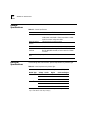
The following documents provide additional information on 3Com
products:
ONline System Concentrator Installation and Operation Guide — Provides
information on the installation, operation, and configuration of the ONline
System Concentrator. This guide also describes the principal features of the
ONline Fault-Tolerant Controller Module.
ONline Ethernet, Token Ring, or FDDI Management Module User’s Guide —
Provides information on the ONline Management Module’s operation,
installation, and configuration. This guide also describes the software
commands associated with the Management Module.
ONcore Switching Hub Installation and Operation Guide — Provides
information on the installation, operation, and configuration of the ONcore
Switching Hub. This guide also describes the principal features of the
ONcore Fault-Tolerant Controller Module.
ONcore Distributed Management Module User’s Guide — Provides
information on the ONcore Distributed Management Module’s operation,
installation, and configuration. This guide also describes the software
commands associated with the Distributed Management Module.
ONcore Distributed Management Module Commands Guide — Describes
each management command by providing details on command format,
use, and description.
For a complete list of 3Com documents, contact your 3Com representative.
Related Documents
Cisco Documents
Reference
Documents
13
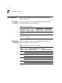
Cisco® CD-ROM documents describe commands and other software-related
information you need to operate the Edge Router module.
The following documents supply related background information:
Case, J., Fedor, M., Scoffstall, M., and J. Davin, The Simple Network
Management Protocol, RFC 1157, University of Tennessee at Knoxville,
Performance Systems International and the MIT Laboratory for Computer
Science, May 1990.
Rose, M., and K. McCloghrie, Structure and Identification of Management
Information for TCP/IP-based Internets, RFC 1155, Performance Systems
International and Hughes LAN Systems, May 1990.
1
INTRODUCTION
This chapter provides an introduction to the 3Com® Edge Router module.
This chapter contains the following sections:
■
Product Overview
■
Edge Router Module Features
Product Overview
The Edge Router module is a serial port-to-Ethernet LAN interconnect
module jointly developed by 3Com and Cisco Systems Inc.
This section provides information on the following topics:
■
Edge Router Module Operation
■
Edge Router Module Architecture
Edge Router
Module Operation
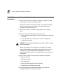
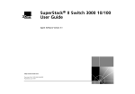
The Edge Router module (Figure 1-1) is designed to:
■
Connect corporate networks and increase wide area connectivity.
■
Support both synchronous and asynchronous routing over serial links using
one local area network (LAN) and up to three wide area network (WAN)
connections.
■
Provide flexible networking connections in multiprotocol environments.
■
Sit at the network’s logical and physical edge, either at a remote site or
central facility.
1-2
C HAPTER 1: INTRODUCTION
Edge Router Module
Console Port
Auxiliary
Port
Network
Backplane
Ethernet
LAN
High Speed
WAN Port
High Speed
WAN Port
Figure 1-1 Typical Edge Router Module Connections
The router module runs Cisco standard software and fully interoperates with
the:
■
3Com ONline Ethernet Router Module
■
Cisco local and remote router servers, such as the AGS+, MGS, and the
Cisco 3000, 4000, 4500, and 7000 series routers.
Product Overview
Edge Router
Module
Architecture
1-3
Each Edge Router module consists of the following components:
■
Carrier – Provides connections to one of three 3Com switching hub
products.
■
Engine – Provides Ethernet-to-WAN port connections.
■
Interface Connector – Connects the carrier to the engine. Both the carrier
and the engine have an interface connector.
The engine mounts to one of three carrier types to form an Edge Router
module for the ONline or ONcore hub products.
The ONline Edge Router module can also be installed in an ONcore
Switching Hub. For detailed information on installing ONline modules in
ONcore switching hubs, refer to the ONcore Switching Hub Installation and
Operation Guide (Document Number 17-00362).
1-4
C HAPTER 1: INTRODUCTION
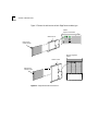
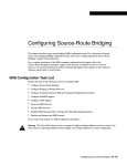
Figure 1-2 shows the architecture of each Edge Router module type.
ONline
System Concentrator
ONline carrier
Edge Router
module engine
ONcore Integrated
System
ONcore carrier
Edge Router
module engine
Figure 1-2 Edge Router Module Architecture
Edge Router Module Features
Edge Router
Module Features
1-5
This section describes the major features of the Edge Router module,
including:
■
Software Options
■
Topology Switching
■
Network Reliability
■
IOS Router Software Updates
■
Memory Upgrades
Software Options
The Edge Router module is available with one of the following software
feature sets:
■
IP/IPX
■
Desktop
■
Desktop plus IBM®
■
Enterprise
The components that make up each software feature set are listed in
Table 1-1.
1-6
C HAPTER 1: INTRODUCTION
Table 1-1 Software Feature Sets
Feature Set
Feature
Category
IP/IPX
Desktop
LAN Support
IP, Bridging,
LAN Extension
Host Software,
Novell® IPX™
Includes
Same as Desktop
IP/IPX
features plus:
DECnet™ IV,
AppleTalk®
Phase 1 and 2
WAN Serial
Support
Dual Synchronous Ports, and Single Asynchronous Auxiliary Port
WAN Services
HDLC, PPP, X.25, Frame Relay, ISDN, SMDS
WAN
Optimization
Header and link compression, dial-on-demand, dial backup, bandwidth-on-demand,
custom and priority queuing, access lists, access security
IP Routing
RIP, IGRP, Enhanced IGRP™, OSPF, BGP, EGP, PIM
Includes standard
features plus: ES-IS and
IS-IS
IBM Support
N/A
Remote source-route
bridging, proxy,
explorer, local
acknowledgement,
SNA local LU address
prioritization,
administrative filtering,
NETBIOS name
caching, NETBIOS
access control filtering
Includes Desktop plus
IBM features plus: serial
tunneling for SDLC
Transport, SDLC
link-level support,
SDLLC, TG/COS, QLLC
Network
Management
Autoinstall, SNMP, TELNET
Protocol
Translation
N/A
N/A
TELNET, LAT, rlogin,
TN3270, X.25
N/A
N/A
Desktop plus IBM
Enterprise
Includes Desktop plus
IBM features plus:
DECnet V, XNS, Banyan
VINES®, OSI, Apollo®
Domain
Edge Router Module Features
Topology Switching
1-7
Using topology switching you can:
■
Switch the ONline Edge Router module among any of three Ethernet
networks (channels) on the hub backplane
■
Switch the ONcore Edge Router module among any of eight Ethernet
networks (channels) on the hub backplane
You perform topology switching using:
■
Network management module commands
■
Simple Network Management Protocol (SNMP)
You do not have to swap cables or move the Edge Router module to move
the routing or bridging functions to a different network within an ONline or
ONcore hub. You can enter a command through one of the 3Com
management modules and the network change is made automatically.
Network Reliability
The Edge Router module lets you implement several levels of reliability in
your network as follows:
■
By routing the Edge Router module’s serial and auxiliary ports in parallel,
you can create up to three redundant links.
■
If the primary link fails, you can have up to two backup links in place to
ensure application availability.
These links can also implement load-balancing to enhance network
performance. An example of a reliable network configuration is shown in
Figure 1-3.
1-8
C HAPTER 1: INTRODUCTION
Ethernet LAN
Edge Router Module
Console Aux
Port
Port
WAN Port
WAN Port
Remote Site
Public
Switched
Telephone
Network
Dial-Up
Link
Primary
Link
Secondary
Link
Main Site
Main Site Router
Main Site Network Connections
Figure 1-3 Network Reliability Configuration
IOS Router
Software Updates
The IOS software in the Edge Router module engine can be updated by
purchasing field-upgradeable software distribution kits. Update your
module to the latest 3Com release of IOS software by downloading new
code to flash memory on the module. New updates are shipped
automatically as part of the 3Com 1-year Router Software Subscription
Service or you can purchase it from 3Com as a single unit update.
Edge Router Module Features
1-9
You can also purchase an upgrade kit to upgrade your IP/IPX, Desktop, or
Desktop plus IBM software to a version with an enhanced feature set.
Contact your 3Com reseller or 3Com Customer Support for more
information and part numbers.
Memory Upgrades
The Edge Router module provides the capability to increase memory to
meet the requirements of large routing table configurations.
Memory is configured on the Edge Router module to match the
requirements of the selected IOS software feature set. Table 1-2 lists the
base memory configurations for each software feature set.
Table 1-2 Memory Configurations
Feature Set
Memory Type
IP/IPX
Desktop
IOS (Flash EPROM)
4 MB (expandable to 8 MB)
Data (DRAM)
4 MB (expandable to 16 MB)
Desktop
plus IBM
Enterprise
8 MB
6 MB
(expandable to
18 MB)
INSTALLING THE EDGE ROUTER
MODULE
2
This chapter contains the following sections:
■
Installation Flowchart
■
Precautionary Procedures
■
Quick Installation
■
Unpacking Procedures
■
Verifying Jumper Plug Positions
■
Configuring DIP Switches
■
Installing the ONline Edge Router Module
■
Installing the ONcore Edge Router Module
2-2
C HAPTER 2: INSTALLING THE EDGE ROUTER M ODULE
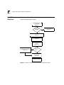
Installation
Flowchart
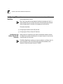
The flowchart in Figure 2-1 identifies the steps required to install and
configure the Edge Router module.
Read Precautionary
Procedures
(page 2-3)
Experienced
installer?
Yes
Go to Quick Installation
(page 2-3)
No
Unpack the Edge Router module
(page 2-6)
Configure DIP switches
(page 2-8)
Install the Edge Router
module
(page 2-12)
Configure the carrier using
management commands
(page 3-2)
Yes
Managed
Hub?
No
Configure the Edge
Router engine
(page 3-9)
Installation complete
Figure 2-1 Flowchart for Installing and Configuring the Edge Router Module
Precautionary Procedures
Precautionary
Procedures
2-3
Electrostatic discharge (ESD) can damage static-sensitive devices on circuit
boards. Follow these precautions when you handle an Edge Router module:
CAUTION: Do not remove the product from any antistatic wrapping until
you are ready to inspect or install the module.
Handle Edge Router modules by the faceplate only.
CAUTION: To avoid damaging the Edge Router module with ESD, use proper
grounding techniques. Before unpacking, you should:
■
■
Quick Installation
Use a foot strap and grounded mat, or wear a grounded static discharge
wrist strap.
Touch a grounded source just before you remove the Edge Router module
from the shipping carton.
This section outlines the steps necessary to complete the installation of the
Edge Router module in unmanaged or managed ONline or ONcore hubs. If
you are already familiar with the procedures required to install a module in
your 3Com hub type, use this table as a checklist. Otherwise, use the
procedures specified in the remainder of this chapter to install the Edge
Router module.
If you encounter problems while following the quick installation steps,
consult the troubleshooting techniques in Chapter 5.
2-4
C HAPTER 2: INSTALLING THE EDGE ROUTER M ODULE
Quick Installation
for Unmanaged
Hubs
Follow the general steps outlined in Table 2-1 to install and configure the
Edge Router module in an unmanaged ONline or ONcore hub.
Table 2-1 Quick Installation for Unmanaged Hubs
Step
Procedure
Refer to:
1
Unpack the module.
Unpacking Procedures on page 2-6
2
Verify the jumper plug positions on
the base and expansion engines.
Verifying Jumper Plug Positions on
page 2-7
3
Configure the carrier for operation in Configuring DIP Switches on page 2-8
an unmanaged hub using DIP
switch settings.
4
Insert the module into an open slot
in the hub.
The appropriate installation instructions
for your hub type in this chapter
5
Attach a management terminal to
the Edge Router module console
port.
Configuring the Edge Router Engine on
page 3-9
6
Configure the engine parameters
using Cisco Systems setup
command.
Cisco Systems Getting Started Guide
7
Attach WAN cables to the 60-pin
universal WAN connectors on the
front panel.
Cable Pinouts on page A-5
Quick Installation
Quick Installation
for Managed Hubs
2-5
Follow the general steps outlined in Table 2-2 to install and configure the
Edge Router module in a managed ONline or ONcore hub.
Table 2-2 Quick Installation for Managed Hubs
Step
Procedure
Refer to:
1
Unpack the module.
Unpacking Procedures on page 2-6
2
Verify the jumper plug positions on
the base and expansion engines
Verifying Jumper Plug Positions on
page 2-7
3
Insert the module into an open slot in The appropriate installation
the hub.
instructions for your hub type in this
chapter
4
Configure the carrier for possible
operation in an unmanaged hub.
5
Attach a management terminal to the Configuring the Edge Router Engine
Edge Router console port.
on page 3-9
6
Configure the carrier using network
management commands.
Configuring the Carrier in a Managed
ONline Hub on page 3-4
or
Configuring the Carrier in a Managed
ONcore Hub on page 3-5
7
Configure the engine parameters
using Cisco Systems setup
command.
Cisco Systems Getting Started Guide
8
Attach WAN cables to the 60-pin
universal WAN connectors on the
front panel.
Cable Pinouts on page A-5
Configuring DIP Switches on page 2-8
2-6
C HAPTER 2: INSTALLING THE EDGE ROUTER M ODULE
Unpacking
Procedures
To unpack the Edge Router module:
1 Verify that the module is the model you ordered by checking the model
number listed on the side of the shipping carton.
Note that the product model number printed on the shipping box differs
from the model number on the product. The model number on the
shipping box contains the prefix 3C9.
2 Remove the module, in its antistatic shielding bag, from the shipping
carton.
3 When you unpack the Edge Router module, you should:
■
■
Use a foot strap and grounded mat, or wear a grounded static discharge
wrist strap.
Touch a grounded source just before you remove the Edge Router
module from the carton.
CAUTION: To avoid damaging the Edge Router module with ESD, use proper
grounding techniques.
Remove the module from the antistatic bag and inspect it for damage.
Always handle modules by the faceplate, being careful not to touch the
components. If the module appears to be damaged, return it to the
antistatic shielding bag, repack it in the shipping carton, and contact your
local supplier.
4 Verify that the contents of the shipment are complete. The shipment
contents are as follows:
■
Edge Router module
■
Rack-mounting kit
■
Edge Router Module Installation Guide for Ethernet
■
Release Notes for the Edge Router module
5 Store the shipping cartons and antistatic wrapping so that you can
repackage the product for storage or shipment.
Verifying Jumper Plug Positions
Verifying Jumper
Plug Positions
2-7
Verify the jumper plug positions on the ONline or ONcore Edge Router
module before proceeding with the installation procedure.
The Edge Router module is equipped with several jumper plugs. The
jumpers are factory-set to the appropriate settings. Do not modify the
jumper settings, except to restore the settings to the required positions.
CAUTION: If you modify any of the factory-set jumper positions, the Edge
Router module may not operate properly.
Table 2-3 lists the default jumper plug positions for the Edge Router
module. If you suspect that any of the jumper positions have been changed,
verify the plug positions using Table 2-3.
.
Table 2-3 Default Jumper Plug Settings
Jumper
Jumper Plug Position
J1
ETH INT
J2
Removed
J4
Inserted
J5
Removed
J9
Removed
J10
WAN 0 EXT
J12
WAN 1 EXT
J13
Removed
J14
Inserted
J15
Removed
J16
Inserted
J17
Inserted
2-8
C HAPTER 2: INSTALLING THE EDGE ROUTER M ODULE
Configuring DIP
Switches
DIP switches let you select the backplane network used by an ONline or
ONcore Edge Router module.
Even if you use a network management module to manage your hub, it is
recommended that you configure the carrier DIP switches to ensure proper
network assignments in the event of management module failure.
This section describes:
Configuring the
ONline Carrier DIP
Switches
■
Configuring the ONline Carrier DIP Switches
■
Configuring the ONcore Carrier DIP Switches
ONline carrier DIP switches let you select the backplane network used by
the Edge Router module. Modules set to the same network in the hub can
communicate with each other.
The ONline Edge Router module can also be installed in an ONcore hub. For
more information, refer to the ONcore Switching Hub Installation and
Operation Guide (Document Number 17-00362).
Configuring DIP Switches
2-9
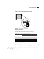
Figure 2-2 shows the ONline carrier DIP switch location.
ON
1
2
3
4
Figure 2-2 ONline Carrier DIP Switch Location
Selecting a Network
Use Table 2-4 to select a network by using the DIP switches.
Table 2-4 ONline Network Selection DIP Switch Settings
Switch Settings
Network Selection
Switch 1
Switch 2
Switch 3
Switch 4
Ethernet_1 (default)
ON
ON
ON
ON
Ethernet_2
ON
OFF
ON
ON
Ethernet_3
OFF
ON
ON
ON
Isolated
OFF
OFF
ON
ON
Isolating the ONline Edge Router Module
To isolate the Edge Router module from all backplane networks, set the DIP
switches to the Isolated position as defined in Table 2-4.
Configuring the
ONcore Carrier DIP
Switches
ONcore carrier DIP switches allow you to set the following configuration
parameters:
2-10
C HAPTER 2: INSTALLING THE EDGE ROUTER M ODULE
■
Enabling or Disabling NVRAM Configuration
■
Selecting a Network
Figure 2-3 shows the ONcore carrier DIP switch location.
ENG 1
ENG 2
CH SEL 0
CH SEL 1
CH SEL 2
CH SEL 3
NV SEL
CH SEL 0
CH SEL 1
CH SEL 2
CH SEL 3
NV SEL
OFF ON
0
1
2
3
4
5
6
7
8
9
Figure 2-3 ONcore Carrier DIP Switch Location
Enabling or Disabling NVRAM Configuration
Two NV SEL DIP switches control whether the ONcore Edge Router module
uses configuration settings stored in NVRAM (non-volatile memory).
■
Switch 4 provides the NVRAM selection for engine bay 1 (top).
■
Switch 9 provides the NVRAM selection for engine bay 2 (bottom).
Configuring DIP Switches
2-11
If the NV SEL DIP switch is:
■
ON (enabled) – The Edge Router module uses configuration settings
stored in its NVRAM. If NVRAM does not contain configuration settings, the
Edge Router modules are assigned to the Isolate_1 network.
■
OFF (disabled) – The Edge Router module uses DIP switch settings.
Selecting a Network
In an unmanaged ONcore hub, the DIP switches determine the network
setting (unless NVRAM configuration settings are enabled).
1 To select a network:
Set the switches according to Table 2-5.
Table 2-5 ONcore Network Selection DIP Switch Settings
Switch Settings
Network
Selection
CH SEL 0
CH SEL 1
CH SEL 2
CH SEL 3
Ethernet_1
(default)
ON
ON
ON
ON
Ethernet_2
OFF
ON
ON
ON
Ethernet_3
ON
OFF
ON
ON
Ethernet_4
OFF
OFF
ON
ON
Ethernet_5
ON
ON
OFF
ON
Ethernet_6
OFF
ON
OFF
ON
Ethernet_7
ON
OFF
OFF
ON
Ethernet_8
OFF
OFF
OFF
ON
Isolate_1
ON
ON
ON
OFF
Isolate_2
OFF
ON
ON
OFF
Isolate_3
ON
OFF
ON
OFF
Isolate_4
OFF
OFF
ON
OFF
Switch combinations not listed in Table 2-5 select Isolate_1.
2 Disable NVRAM by setting the NV SEL DIP switch to the off position.
2-12
C HAPTER 2: INSTALLING THE EDGE ROUTER M ODULE
Installing the
ONline Edge
Router Module
This section describes how to install the ONline Edge Router module in an
ONline hub.
If you are installing:
■
An ONcore Edge Router module, refer to Installing the ONcore Edge Router
Module on page 2-13.
■
An ONline Edge Router module in an ONcore hub, refer to the ONcore
Switching Hub Installation and Operation Guide (Document Number
17-00362)
You do not need to power off the ONline hub to install or remove the Edge
Router module. You can insert the module while the hub is operating (this
is called a hot swap).
To install the Edge Router module in an ONline hub:
1 Use one of the following proper grounding techniques when you install the
Edge Router module:
■
■
Properly ground yourself prior to handling the module.
Attach a static wrist guard to yourself or touch a grounded static mat
prior to handling the module.
2 Locate an open slot in the ONline hub. If necessary, remove a blank panel
on the hub to expose a slot.
3 Insert the module into the slot’s board guides and slide it into the hub by
pressing firmly at the top and bottom of the faceplate. Make sure the
connectors are well-seated into the backplane of the hub.
Installing the ONcore Edge Router Module
2-13
4 Using your fingers, tighten the two spring-loaded screws on the front of the
module faceplate (Figure 2-4). Do not overtighten.
Board guide
Hub backplane
Screws
Board guide
Faceplate
Figure 2-4 Installing the Edge Router Module in an ONline Hub
Installing the
ONcore Edge
Router Module
You do not need to power off the ONcore hub to install or remove the
Edge Router module. You can insert the module while the hub is operating
(this is called a hot swap).
To install the Edge Router module in an ONcore hub:
1 Use one of the following proper grounding techniques when you install the
Edge Router module:
■
■
Properly ground yourself prior to handling the module.
Attach a static wrist guard to yourself or touch a grounded static mat
prior to handling the module.
If you already have a management terminal connected to your ONcore hub,
you can verify the hub has enough power for the new Edge Router module
by entering the SHOW POWER BUDGET command. Refer to Appendix A for
details on power requirements.
Refer to the ONcore Distributed Management Module Commands Guide for
information on the SHOW POWER BUDGET command.
2 Locate an open slot in the ONcore hub. If necessary, remove a blank panel
to expose a slot.
2-14
C HAPTER 2: INSTALLING THE EDGE ROUTER M ODULE
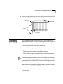
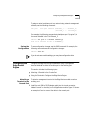
3 Insert the module into the board guides at the top and bottom of the slot
and slide it into the hub by pressing firmly at a point slightly below the
center of the faceplate (Figure 2-5).
Figure 2-5 Installing the Edge Router Module in an ONcore Hub
Installing the ONcore Edge Router Module
2-15
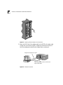
4 Close the ejectors (Figure 2-6).
Opened
ejector
Closed
ejector
Figure 2-6 Opened and Closed Module Ejectors
5 Using your fingers, tighten the two spring-loaded screws on the front of the
Edge Router module faceplate (do not overtighten).
CONFIGURING THE EDGE
ROUTER MODULE
3
This chapter contains the following sections:
■
Managed Configuration Overview
■
Attaching a Management Terminal
■
Configuring the Carrier in a Managed ONline Hub
■
Configuring the Carrier in a Managed ONcore Hub
■
Configuring the Edge Router Engine
If you are installing the Edge Router module in an unmanaged ONline or
ONcore hub, you must configure the carrier using DIP switches. Refer to
Configuring DIP Switches on page 2-8. When you finish setting the DIP
switches, go to Configuring the Edge Router Engine on page 3-9.
3-2
C HAPTER 3: CONFIGURING THE EDGE ROUTER M ODULE
Managed
Configuration
Overview
You can manage an ONline or ONcore carrier using a network management
module installed in the same hub.
This section provides a brief overview of the following topics:
■
3Com Management Modules
■
Using Management Commands
■
Using ONdemand NCS
■
Carrier Configuration Tasks
3Com Management
Modules
You can manage the ONline or ONcore carrier through SNMP or
management commands if a management module is installed.
Management modules for ONline and ONcore hub types include:
■
ONline – An ONline Ethernet Management Module (EMM) running software
Version v4.10 or later installed in the same hub as the Edge Router module
or a Token Ring Management Module (TRMM) running software
Version v3.30 or later installed in the same hub as the Edge Router module.
■
ONcore – A Distributed Management Module (DMM) running software
Version v2.30 or later installed in the same hub as the Edge Router module.
Using Management
Commands
You can use management commands to make basic changes to carrier
configuration settings. For complete instructions on using management
commands to manage the carrier, refer to the guide for the management
module for your platform.
ONline management documentation includes:
■
ONline Ethernet Management Module Installation and Operation Guide
(Document Number 17-00087)
■
ONline Management Commands Guide (Document Number 17-00403)
■
ONline Token Ring Management Module User’s Guide
(Document Number 17-00211)
For ONcore management, refer to the ONcore Distributed Management
Module Commands Guide (Document Number 17-00372)
Attaching a Management Terminal
3-3
The 3Com ONdemand™ Network Control System (NCS) is an SNMP
manager with a graphical user interface. For instructions on using
ONdemand NCS to manage the carrier, refer to one of the following
documents:
Using ONdemand
NCS
■
Transcend Enterprise Manager ONdemand Management for Multi-Function
Hubs, Version 4.0 for UNIX (Document Number 17-00320)
■
ONdemand Network Control System for Windows User’s Guide (Document
Number 17-00472)
Carrier
Configuration Tasks
To configure an ONline or ONcore Edge Router carrier in a managed hub:
1 Attach a management terminal to the console port of the network
management module (TRMM, DMM, or EMM).
2 Use the management terminal to configure the carrier using 3Com network
management commands.
Attaching a
Management
Terminal
Use a terminal (or workstation running a terminal emulation program) to
configure the Edge Router carrier.
Attach a terminal to a port on the network management module to
configure or modify hub parameters, including:
■
Selecting networks for modules in the hub
■
Changing configurations
■
Reporting the condition of any module in the hub
For information on attaching and configuring a management terminal for
your hub type, refer to the documents specified in Using Management
Commands on page 3-2.
3-4
C HAPTER 3: CONFIGURING THE EDGE ROUTER M ODULE
Configuring the
Carrier in a
Managed ONline
Hub
This section describes how to use network management commands to
configure ONline carriers installed in an ONline System Concentrator. This
section contains the following topics:
■
Selecting a Network
■
Saving the Configuration
When you install the carrier in a hub with a management module installed,
the network defaults to isolated mode (Isolate_1). You must assign a
network as described below.
Selecting a Network
The engine connects to the backplane through a carrier module port on the
ONline carrier. You can assign the carrier module port to:
■
One of three Ethernet backplane networks
■
Isolated mode
For details on backplane networks, refer to the ONline System Concentrator
Installation and Operation Guide (Document Number 17-00417).
To assign the carrier module ports to a network using the network
management software, use the following command:
ONline> set port slot.port network
{ethernet_1 ... _3}
{isolated_1}
For example, the following command sets port 1 in the ONline carrier
installed in slot 3 to the Ethernet 2 backplane network:
ONline> set port 3.1 network ethernet_2
Port 03.01 network id set to ETHERNET_2
Saving the
Configuration
To save configuration changes, use the SAVE command. For example, the
following command saves all configuration changes:
ONline> save all
If you do not save module settings, you may lose configuration data.
Configuring the Carrier in a Managed ONcore Hub
Configuring the
Carrier in a
Managed ONcore
Hub
3-5
This section describes the possible sources of ONcore carrier configuration
settings, the factors that determine the configuration source the carrier uses,
and how to configure the carrier using network management commands.
This section contains the following topics:
■
ONcore Carrier Configuration Sources
■
Hot Swapping an ONcore Module
■
Determining the Configuration Source
■
Selecting a Network
■
Saving the Configuration
When you install the carrier in a hub with a management module installed,
the network defaults to isolated mode (Isolate_1). You must assign a
network as described in the sections that follow.
ONcore Carrier
Configuration
Sources
In a managed hub (a hub with a DMM installed), the ONcore carrier obtains
its configuration settings from one of the following sources:
■
DMM settings
■
Carrier NVRAM settings
■
Carrier DIP switch settings
■
Carrier default settings
DMM Settings
The DMM can provide configuration settings to the ONcore carrier if you are
performing a hot swap. For more information on hot swapping, refer to Hot
Swapping an ONcore Module on page 3-7.
3-6
C HAPTER 3: CONFIGURING THE EDGE ROUTER M ODULE
Carrier NVRAM Settings
The ONcore carrier can store configuration settings in its NVRAM
(non-volatile random access memory), which it can use when powering on
in either a managed or unmanaged hub. Two NVRAM DIP switches control
whether or not the carrier uses NVRAM settings. For information on setting
the NVRAM DIP switches, refer to Enabling or Disabling NVRAM
Configuration on page 2-10.
When the ONcore carrier ships from the factory, the NVRAM does not
contain any configuration settings.
The carrier stores configuration settings in NVRAM when either of the
following occurs:
■
You use a DMM configuration command or an SNMP manager to change a
carrier configuration setting. For example, if you use the SET PORT
NETWORK command to change a carrier port network assignment, the
carrier stores the new network assignment in its NVRAM.
The carrier stores the new setting as soon as you issue the command. The
SAVE command does not affect the contents of NVRAM.
■
The DMM sends configuration settings to the carrier during a hot swap. For
a definition of hot swap, refer to Hot Swapping an ONcore Module on
page 3-7.
Carrier DIP Switch Settings
The carrier contains a DIP switch that you can use to configure network
assignments. For more information on DIP switch settings, refer to
Configuring the ONcore Carrier DIP Switches on page 2-9.
Carrier Default Settings
In some cases, the carrier uses default configuration settings contained in its
software. The default network assignment for the ONcore carrier is Isolate_1.
Configuring the Carrier in a Managed ONcore Hub
Hot Swapping an
ONcore Module
3-7
You can remove a module from the ONcore hub and install an identical
module in the same slot without powering off the hub. This is called a hot
swap. Whether or not you hot swap the Edge Router module affects which
configuration source the carrier uses.
When you perform a hot swap, the DMM transfers to the new carrier the
configuration used by the old carrier. The new carrier saves the settings in
its NVRAM.
The DMM transfers the configuration to the new carrier only if it has a saved
configuration for the old carrier installed in that slot. The DMM saves the
configuration when you perform one of the following:
■
Issue the SAVE command.
■
Use SNMP to make the configuration changes to the carrier. The DMM
automatically saves the changes.
■
Reset or power-cycle the DMM. The DMM automatically acquires and saves
the NVRAM configurations of all installed modules.
Swapping in a new carrier that contains a different engine from the old
carrier is still a hot swap. Only the carrier models must be the same.
3-8
C HAPTER 3: CONFIGURING THE EDGE ROUTER M ODULE
Determining the
Configuration
Source
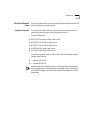
Table 3-1 shows how to determine the carrier configuration source
.
Table 3-1 Determining the Carrier Configuration Source
Hot Swap?
DMM DIP
Configuration*
NVRAM DIP
Switch
Carrier
Configuration Source
Yes
Disable
ON or OFF
DMM passes the old
configuration settings to the
new carrier.
Enable
ON
NVRAM settings†
OFF
DIP switch settings
ON
NVRAM settings†
OFF
Default settings
ON
NVRAM settings†
OFF
DIP switch settings
No‡
Disable
Enable
* Use the SHOW DEVICE command to view the DIP configuration setting. Use the SET DEVICE
DIP_CONFIGURATION command to change the DIP configuration setting.
† If the carrier does not have configuration settings stored in NVRAM, it uses default settings.
If the DMM detects a problem with the NVRAM configuration, it forces the carrier to use
default settings. For example, if you install the carrier with ports assigned to Ethernet_8 into an
ONcore hub model that does not support Ethernet_8. If the configuration problem is port
level, the DMM forces only the affected ports to use default settings.
‡ The DMM must be fully initialized when you install the carrier module.
Selecting a Network
The Edge Router engine connects to an Ethernet network through a
backplane port on the ONcore carrier. A base engine installed in ONcore
carrier engine bay 1 uses carrier backplane port 1. A base engine installed in
ONcore carrier engine bay 2 uses carrier backplane port 5.
You can assign a carrier backplane port to:
■
One of eight Ethernet backplane networks
■
One of four Isolated backplane networks
For details on backplane networks, refer to the ONcore Switching Hub
Installation and Operation Guide (Document Number 17-00362-5).
Configuring the Edge Router Engine
3-9
To assign a carrier backplane port to a network using network management
software, use the following command:
set port
slot.port network {ethernet_1 ... ethernet_8}
{isolated_1 ... isolated_4}
For example, the following command sets backplane port 1 (engine 1) in
the carrier installed in slot 3 to Ethernet_2:
ONcore> set port 3.1 network ethernet_2
Port 03.01 network id set to ETHERNET_2
Saving the
Configuration
To save configuration changes, use the SAVE command. For example, the
following command saves all configuration changes:
ONcore> save all
If you do not save module settings, you may lose configuration data.
Configuring the
Edge Router
Engine
Configure the Edge Router engine parameters using a management
terminal attached to either the console port or the auxiliary port.
This section includes the following topics:
Attaching a
Terminal to the
Console Port
■
Attaching a Terminal to the Console Port
■
Using the Terminal to Configure the Edge Router Engine
To attach a management terminal to the Edge Router module console or
auxiliary port:
1 Install the mini-DIN to DB-25 adapter cable into the circular connector
labeled “console” or “auxiliary” on the Edge Router module. Figure 3-1 shows
an example of how to connect the cable to the console port.
3-10
C HAPTER 3: CONFIGURING THE EDGE ROUTER M ODULE
Figure 3-1 Attaching a Terminal Cable to the Console Port
2 Attach the DB-25 end of the adapter cable to the RS-232 null modem cable
coming from your terminal. Figure 3-2 shows the terminal connections to
both the management module and the Edge Router console port.
• Configure LAN Access module
Configure the Edge Router engine
Assign Edge Router module to network and
report module
status module to network
• Configure
• Report module status
Figure 3-2 Terminal Connections
Configuring the Edge Router Engine
3-11
Console and auxiliary port specifications are provided in Table 3-2 and
Table 3-3, respectively.
Table 3-2 Console Port Information
Interface
Connector
Transmission
Type
RS-232
8-pin mini-DIN
DTE
Protocol
Asynchronous, 9600, 8-bit data,
1 stop bit, no parity, XON/XOFF
Table 3-3 Auxiliary Port Information
Interface
Connector
Transmission
Type
RS-232
8-pin mini-DIN
DTE
Protocol
Asynchronous or synchronous, 9600,
8-bit data, 1 stop bit, no parity,
XON/XOFF
Mini-DIN connector pinouts are provided in Appendix A.
The Edge Router module is shipped autoconfigured for connection to a
network running NetWare®. If you are not connected to a NetWare network,
you may see the following message:
The IPXNetwork for LocalPath ms_ethernet couldn’t be
learned.
Ignore this message and continue with the appropriate configuration.
Using the Terminal
to Configure the
Edge Router Engine
Edge Router engine documentation is included on the Cisco Systems
CD-ROM that is shipped with the Edge Router module.
Refer to the Cisco Router Products Configuration and Reference Guide for
information on configuring parameters for the Edge Router module.
MONITORING EDGE ROUTER
MODULE OPERATION
4
This chapter contains the following sections:
Monitoring Edge
Router Module
Operation
■
Monitoring Edge Router Module Operation
■
Showing Module Configuration and Status
The LEDs on the front panel of the Edge Router module allow you to
monitor the status of the module and ports. When you install the Edge
Router module in the hub:
1 The Router Status (RTR) LED is off if the router is booting (initializing).
2 The Router Status (RTR) LED illuminates once the router boot software is
running.
3 The Module Status (S) LED blinks while the module is attempting
communication with the carrier board.
4 The Module Status (S) LED stays illuminated once communication is
established with the carrier board.
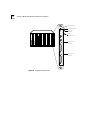
Figure 4-1 shows the LED locations. Each LED indicates the state of the
module or port as described in Table 4-1.
4-2
C HAPTER 4: MONITORING EDGE ROUTER MODULE OPERATION
Router Status
RTR
S
EO
Reset
CONSOLE
Module Status
Ethernet
Activity
Reset
Pushbutton
AUX
S0
ACT
S1
ACT
2103R-CS
Figure 4-1 Edge Router Module LEDs
Serial Port 0
Activity
Serial Port 1
Activity
Showing Module Configuration and Status
4-3
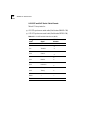
Each LED is described in Table 4-1.
Table 4-1 Module LED Interpretations
LED Name
Color
State
Indicates
S
Green
Blinking
The module is in boot mode
and is attempting
communication with the
carrier board.
On
Remains lit as long as there
is active communication
with the carrier board.
On
Router is functioning
properly.
Off or Blinking
Router is not functioning.
Replace the module.
Yellow
Blinking
Traffic is being passed.
Yellow
Blinking
Traffic is being passed on
serial port 0.
Yellow
Blinking
Traffic is being passed on
serial port 1.
(Module Status)
RTR
Green
(Router Status)
E0 Activity
(Ethernet Activity)
S0
(Serial Port 0 Activity)
S1
(Serial Port 1 Activity)
Showing Module
Configuration
and Status
This section describes NMM commands that show module configuration
and status.
To show configuration and status for an Edge Router module, use the
following network management module commands:
■
SHOW MODULE
■
SHOW PORT
4-4
C HAPTER 4: MONITORING EDGE ROUTER MODULE OPERATION
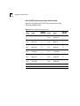
Using the SHOW
MODULE Command
The SHOW MODULE command displays information about a specific
module.
The syntax for the SHOW MODULE command is:
SHOW MODULE slot
{verbose}
{no_verbose}
The following command displays verbose information for an Edge Router
module installed in slot 1 of an ONcore hub:
ONcore> show module 1.1 verbose
Slot
Module
Version Network
----- --------- ------- ------01.01 6102M-SDEK v1.00
PER_PORT
General Information
---------------2103R-CSDI
6102M-SDEK: ONcore ONdeck Ethernet Carrier Module
Boot Version:
v1.00
ENGINE 1 Model Number:
Description:
Expansion Module Model Number:
Native Software Version:
Native Boot Software Version:
IP Default Gateway:
Mailbox Version:
No. Backplane Ports:
No. Front Ports:
Engine Status: OKAY
NVRAM Dip Switch State:
Module Capabilities:
2103R-CSDI
Edge Rtr DIBMSW
ENGINE 2 Model Number:
Description:
Expansion Module Model Number:
Native Software Version:
Native Boot Software Version:
IP Default Gateway:
Mailbox Version:
No. Backplane Ports:
No. Front Ports:
Engine Status:
NVRAM Dip Switch State:
Module Capabilities:
NOT INSTALLED
v10.03
v4.14
0.0.0.0
0.00.0
1
2
DISABLED
MACCFG;IPCFG;
0.0.0.0
0.00.0
4
0
NOT INSTALLED
DISABLED
-NONE-
Showing Module Configuration and Status
4-5
The following command displays verbose information for an Edge Router
module installed in slot 6 of an ONline hub:
ONline> show module 6 verbose
Slot Module
----- --------06
2103R-CSD
Version Network General Information
------ ------------------v1.07
PER_PORT Port(s) are up
5103R-CSD: Ethernet Edge Rtr DeskSW
Module Capabilities:
No. Front Panel Ports:
Boot Version:
Native Software Version:
Native Boot Software Version:
MACCFG;IPCFG;
2
v1.01
x10.00
x51.30
No_Verbose is the default option for the SHOW MODULE command. Use the
No_Verbose option to display summary information for the carrier. The
following command displays summary information for an Edge Router
module installed in slot 1 of an ONcore hub:
ONcore> show module 1.1
Slot Module
Version Network General Information
----- --------- ------ ------------------01.01 6102M-SDEK v1.00
PER_PORT 2103R-CSDI
4-6
C HAPTER 4: MONITORING EDGE ROUTER MODULE OPERATION
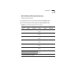
Using the SHOW
PORT Command
The SHOW PORT command displays information about a single port or all
ports.
The syntax for the SHOW PORT command is:
SHOW PORT slot.port {verbose}
{no_verbose}
The following command displays verbose information for port 1 on an
Edge Router module installed in slot 1 of an ONcore hub:
ONcore> show port 1.1 verbose
Port Display for Module 6102M-SDEK:
Port
Mode
Status
Network
General Information
----- ------ ------- ---------------------01.01 LOGICAL OKAY ETHERNET_4 2103R-CSDI
Port Connector:
IP Address:
Subnetwork Mask:
Station Address:
Dip Network Setting:
BACKPLANE
2.0.0.2
ff.00.00.00
00-00-0c-c0-3d-63
ETHERNET_4
The following command displays verbose information for port 1 on an
Edge Router module installed in slot 4 of an ONline hub:
ONline> show port 4.1 verbose
Port Display for Module 5103R-CSD:
Port Mode
Status Network
General Information
----- ----------------------------------04.01 LOGICAL
OKAY
ETHERNET_1
Port Connector:
IP Address:
Station Address:
Capabilities:
Native Port Number:
BACKPLANE
151.104.15.39
-NONE0
Showing Module Configuration and Status
4-7
No_Verbose is the default option for the SHOW PORT command. Use the
No_Verbose option to display summary information for the carrier ports. The
following command displays summary information for port 1 on an Edge
Router module installed in slot 1 of an ONcore hub:
ONcore> show port 1.1
Port Display for Module 6102M-SDEK:
Port
---01.01
Mode
Status
Network
General Information
---------------------------------LOGICAL OKAY
ETHERNET_4
2103R-CSDI
5
TROUBLESHOOTING
This chapter provides hardware troubleshooting information you can use if
the Edge Router module fails to operate correctly. If after reviewing the
information in this chapter, you cannot correct the problem, contact your
3Com representative for further assistance.
For software-related troubleshooting information, refer to the appropriate
Cisco Systems manual.
This chapter contains the following sections:
■
Troubleshooting Startup Problems
■
Troubleshooting Network Connectivity Problems
■
Troubleshooting WAN Connectivity Problems
■
Correcting Operating Malfunctions
5-2
C HAPTER 5: TROUBLESHOOTING
Troubleshooting
Startup Problems
This section describes how to troubleshoot startup problems by monitoring
the LEDs on the Edge Router module.
This section describes:
■
Troubleshooting Router-Specific Problems
■
Troubleshooting Mailbox Interface Problems
■
Troubleshooting 3Com Carrier Problems
Troubleshooting
Router-Specific
Problems
When you first install the Edge Router module in an ONline or ONcore hub
the Cisco engine runs a full set of hardware diagnostic tests. If the engine
fails diagnostics, the Router (RTR) LED does not illuminate or will flash. This
indicates a problem with the router hardware or software. Refer to the
appropriate Cisco Systems troubleshooting documentation for corrective
action.
Troubleshooting
Mailbox Interface
Problems
ONline and ONcore Edge Routers use a hardware mailbox interface that
allows the Cisco engine to communicate with the 3Com carrier board
during powerup. If the 3Com mailbox does not establish communication
with the engine, the following message is reported to the engine console
port:
%MAILBOX-3-INITFAIL:Mailbox initialization failure.
Not getting interrupts. Mailbox offline.
If you see this message, contact your 3Com representative for assistance.
Troubleshooting
3Com Carrier
Problems
Before mailbox communication is initialized and established between the
Cisco engine and the 3Com carrier, the Module Status (S) LED on the front
panel of the Edge Router module blinks slowly. If communication is
established successfully, the Status LED illuminates and stays on solid. If the
Status LED does not light, the 3Com carrier board has malfunctioned.
Contact your 3Com representative for assistance. Refer to Appendix B for
instructions on contacting Technical Support for you product.
Troubleshooting Network Connectivity Problems
Troubleshooting
Network
Connectivity
Problems
5-3
If the Edge Router module does not appear to be routing traffic properly on
the network, it may indicate that there is no connection to the network.
Try performing one or more of the following troubleshooting actions:
■
For ONline and ONcore Edge Router modules only, use the 3Com
management interface (for example, ONline management module) to verify
that the Edge Router module backplane port is set to the appropriate
backplane network (channel).
■
Using the Cisco terminal interface, verify that the following parameters are
set correctly:
■
IP address
■
Subnet mask
■
Default gateway
■
Use the ping utility to confirm that there is network connectivity.
■
Use the cisco>show interfaces ethernet 0 command to verify that
the interface is up and running. This command reports Ethernet statistics
that aid you in troubleshooting the network.
If the interface is down, you may need to use the Cisco configuration editor
to issue the no shutdown command. The no shutdown command
restarts a disabled interface.
■
Verify that your router configuration is valid. Refer to the Cisco Systems
Troubleshooting Internetworking Systems guide for more information.
5-4
C HAPTER 5: TROUBLESHOOTING
Troubleshooting
WAN
Connectivity
Problems
If you suspect that the Edge Router module has lost WAN connectivity,
perform one or more of the following troubleshooting actions:
■
Verify that you have the correct cable for your configuration. Refer to
Appendix A, Specifications, for a list of approved cables, cable
specifications, and pinouts.
■
If you are using a:
■
■
DCE cable — Verify that a clock rate is defined in the router WAN
interface configuration.
DTE cable — Verify that no clock rate is defined in the router WAN
interface configuration.
■
Verify that the cable’s 60-pin WAN connector is not plugged in backwards.
■
Ensure that the router configuration does not have a SHUTDOWN command
associated with the interface.
■
Verify that your router configuration is valid. Refer to the Cisco Systems
Troubleshooting Internetworking Systems guide for more information.
Correcting Operating Malfunctions
Correcting
Operating
Malfunctions
5-5
Table 5-1 lists the symptoms of operating malfunctions for the Edge Router
module and shows possible causes and corrective actions for these
malfunctions.
Table 5-1 Troubleshooting Malfunctions
Symptom
Possible Cause
Corrective Action
Module does not power
on.
Module is not fitted
correctly against
backplane.
Remove the module from the slot
and replace it in the slot to ensure
that the module is fitted correctly.
Place the module in a different slot
in the hub.
The hub is receiving
no electrical power.
Check that the hub is receiving
power.
Test for power at the wall outlet by
plugging in another device.
Select another outlet on a different
circuit if necessary.
Attached terminal does
not operate.
The terminal is
malfunctioning.
Follow the troubleshooting
procedures recommended by the
terminal manufacturer.
Cables are
unattached.
Make sure that the cable
connections at both ends are secure.
Cables are not the
correct type.
Make sure that the cable attached to
the terminal conforms to the
specification as described in
Appendix A.
The console or
auxiliary port is
configured
incorrectly.
Check the console port and auxiliary
port configurations.
You can make a TELNET connection
to the router to verify port
configurations.
Refer to the Cisco Router Products
Configuration and Reference
documentation for more
information. Verify that the port is
configured as 8-bit data, no parity,
1 stop bit, 9600 baud rate, with flow
control parameters set to Xon and
Xoff.
5-6
C HAPTER 5: TROUBLESHOOTING
Table 5-1 Troubleshooting Malfunctions (continued)
Symptom
Possible Cause
Corrective Action
The terminal fails to
The terminal is not
Power off the terminal, wait
respond to commands
receiving commands. 30 seconds, and then power it on
entered at the keyboard.
again.
The keyboard cable
is attached
incorrectly.
If the terminal still does not respond
to commands, power off the
terminal and disconnect the
keyboard cable. Then reattach the
keyboard cable and power on the
terminal.
The console port is
malfunctioning.
Check the state of the LEDs on the
front of the module as shown in
Table 4-1. If the LEDs indicate a
problem, contact your supplier for
assistance.
A
SPECIFICATIONS
This appendix contains the hardware specifications for the 3Com Edge
Router module in the following sections:
■
General Specifications
■
Electrical Specifications
■
Environmental Specifications
■
Mechanical Specifications
■
Hub Capacities
■
Cable Pinouts
A-2
APPENDIX A: SPECIFICATIONS
General
Specifications
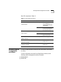
Table A-1 General Specifications
Processor
20 MHz Motorola® 68EC030
Memory
4 MB DRAM (expandable to 16 MB)
4 MB system code (PROM or Flash) (expandable to 8 MB)
32 KB non-volatile configuration RAM
Electrical
Specifications
Network Interface
Options
1 Ethernet and 2 synchronous serial
Ethernet Interface
Backplane connection
Synchronous Serial
Interfaces
RS-232, RS-449, V.35, X.21 (NRZ/NRZI and DTE/DCE),
EIA-530 (NRZ/NRZI and DTE). All serial cables use a DB-60
connector.
Console and Auxiliary
Ports
Asynchronous serial (mini-DIN)
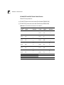
The following table lists the basic power requirements by module type.
Table A-2 Power Requirements by Module Type
Power Requirements (AMPs)
Module Type
Voltage Carrier
Engine
Carrier and Engine
ONline
+5
.40
2.60
3.00
+12
0
0.21
.21
-12
0
0.21
.21
+5
.60
2.60
3.20
+12
0
0.21
.21
-12
0
0.21
.21
*
ONcore
* ONcore power requirements are based on an Edge Router engine installed in
bay 1 of the ONcore carrier. Bay 2 is empty.
Environmental Specifications
A-3
Environmental
Specifications
Table A-3 Environmental Specifications
Operating Temperature
0° to 50° C (32° to 122° F)
Storage Temperature
-10° to 66° C (22° to 138° F)
Humidity
Less than 95%, noncondensing
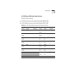
Table A-4 lists the BTU/hr calculations for the Edge Router module installed
in each hub type.
Table A-4 BTU/hr Calculations
Hub Type
BTU/hr
ONline
68.28
ONcore
68.28
Mechanical
Specifications
Table A-5 Mechanical Specifications
Hub Type
Dimensions
ONline
Width
1.0”
Length
10.275”
Height
8.5”
Weight
1.5 lbs
Width
1.0”
Length
10.275”
Height
14.37”
Weight
2.0 lbs
ONcore
A-4
APPENDIX A: SPECIFICATIONS
Hub Capacities
ONline Hub
Capacities
This section provides guidelines for installing Edge Router modules in
ONline or ONcore hubs.
Follow the guidelines in Table A-6 when installing ONline Edge Router
modules in an ONline System Concentrator.
.
Table A-6 ONline Module Restrictions
ONline System Model
Power
Concentrator
Numbers (Watts)
ONcore Hub
Capacities
Maximum Number
of Modules (both
serial ports in use)
Maximum Number
of Modules (one
serial port in use)
17-Slot
Concentrator
5017C
325
5
10
6-Slot
Concentrator
5006C
200
and
5006C-FT
3
6
Follow the guidelines in Table A-7 when installing ONcore Edge Router
modules in an ONcore 10-slot or 17-slot hub.
Table A-7 ONcore Hub Capacities for ONcore Modules
Number
of Power
Supplies
Maximum Number of
Slots
Maximum Number of Modules Modules
per Hub (fault-tolerant mode)
(non-fault-tolerant mode)
1
10-Slot
N/A
8
17-Slot
N/A
8
10-Slot
8
9
17-Slot
8
14
10-Slot
9
9
17-Slot
14
16
10-Slot
N/A
N/A
17-Slot
16
16
2
3
4
Cable Pinouts
A-5
Follow the guidelines in Table A-8 when installing ONline Edge Router
modules in an ONcore 10-slot or 17-slot hub.
.
Table A-8 ONcore Hub Capacities for ONline Modules
Number
of Power
Supplies
Slots per
Hub
Maximum Number of
Modules (both serial
ports in use)
Maximum Number of
Modules (one serial
port in use)
1
10-Slot
7
10
17-Slot
2
3
4
1
14
10-Slot
10
10
17-Slot
14
17
10-Slot
10
10
17-Slot
17
17
10-Slot
10
10
17-Slot
17
17
1 If hub is set to fault-tolerant mode, apply restrictions for 1 power supply.
Cable Pinouts
Use the information in this section to ensure that the cables and connecting
hardware meet requirements. For proper operation, use only approved
cables when you install all equipment.
The console and auxiliary ports on the Edge Router module require a
mini-DIN to DB-25 serial port adapter cable. You can use a cable that meets
the specifications described in this section or you can purchase the 3Com
OpenHub Management Cable (Part Number OHPMGT-CAB).
The OpenHub Management Cable has a:
■
Mini-DIN connector — Plugs into the console or auxiliary port on the Edge
Router module.
■
DB-25 connector — Plugs into the cable of the peripheral device.
To connect the mini-DIN to DB-25 cable to another DTE device, use a null
modem adapter.
A-6
APPENDIX A: SPECIFICATIONS
This section describes:
■
Console Port Pinouts
■
Auxiliary Port Pinouts
■
DB-25 Null Modem Cable
■
Serial Port Pinouts
Console Port
Pinouts
This section lists the cable pinouts for the:
■
DTE console port
■
Mini-DIN to DB-25 modem cable
DTE Console Port
Table A-9 lists pinouts for the console port on the Edge Router module.
Table A-9 Console Port Pinouts (DTE)
Pin
Signal
Input/Output
1
DTR
Output
2
Not Connected
3
TXD
4
GND
5
RXD
6
Not Connected
7
DCD
8
Not Connected
Output
Input
Input
Cable Pinouts
A-7
Figure A-1 identifies the pins that the 8-pin mini-DIN port uses.
6
7
3
8
4
1
5
2
Figure A-1 Mini-DIN Serial Port Pinouts
Mini-DIN to DB-25 Modem Cable
Table A-10 lists console port pinouts for the 3Com OpenHub™ Management
Cable (mini-DIN to DB-25 modem adapter cable).
Table A-10 Console Port Pinouts (Mini-DIN to DB-25 Modem Cable)
Mini-DIN
DB-25
Pin
Signal
Pin
Signal
Input/Output
1
DTR
20
DTR
Output
2
Not Connected
5
CTS
3
TXD
2
TXD
4
GND
7
GND
5
RXD
3
RXD
6
Not Connected
4
RTS
7
DCD
8
DCD
8
Not Connected
17
RTXC
Output
Input
Input
A-8
APPENDIX A: SPECIFICATIONS
Auxiliary Port
Pinouts
Table A-11 lists the cable pinouts for the auxiliary port on the Edge Router
module.
Table A-11 Auxiliary Port Pinouts (DTE)
Pin
Signal
Input/Output
1
DTR
Output
2
CTS
Input
3
TXD
Output
4
GND
5
RXD
Input
6
RTS
Output
7
DCD
Input
8
Not Connected
Mini-DIN to DB-25 Modem Cable
Table A-12 lists auxiliary port pinouts for the 3Com OpenHub Management
Cable (mini-DIN to DB-25 modem adapter cable).
Table A-12 Auxiliary Port Pinouts (Mini-DIN to DB-25 Modem Cable)
Mini-DIN
DB-25
Pin
Signal
Pin
Signal
Input/Output
1
DTR
20
DTR
Output
2
CTS
5
CTS
Input
3
TXD
2
TXD
Output
4
GND
7
GND
5
RXD
3
RXD
Input
6
RTS
4
RTS
Output
7
DCD
8
DCD
Input
8
Not Connected
17
RTXC
Cable Pinouts
A-9
DB-25 Null Modem
Cable
Use a null modem cable to connect the Edge Router module to another DTE
device (for example, a dumb terminal).
Serial Port Pinouts
This section lists cable pinouts for each type of synchronous serial cable
supported by the serial ports on the Edge Router module.
This section describes:
■
EIA-530 DTE Synchronous Serial Cable Pinouts
■
RS-232 DTE and DCE Serial Cable Pinouts
■
RS-449 DTE and DCE Serial Cable Pinouts
■
V.35 DTE and DCE Serial Cable Pinouts
■
X.21 DTE and DCE Serial Cable Pinouts
In the following tables, serial pinouts for DTE and DCE cables use arrows to
indicate signal direction:
■
→ indicates DTE to DCE
■
← indicates DCE to DTE
All serial cables have a DB-60 connector on the module end. The following
pinouts represent only the module ends of the cables. Due to the small pins
on the DB-60 connector, you should not attempt to manufacture or solder
these cables.
A-10
APPENDIX A: SPECIFICATIONS
EIA-530 DTE Synchronous Serial Cable Pinouts
Table A-13 lists pinouts for EIA-530 DTE synchronous serial cable
(Part Number ERM530-CAB).
Table A-13 EIA-530 DTE Cable Pinouts (DB-25)
25 Pin1
Signal
Direction
DTE DCE2
25 Pin
Signal
DTE DCE
Direction
J2-1
Shield
—
J2-8
CF(A), DCD+
←
—
—
—
J2-10
CF(B), DCD-
←
J2-2
BA(A), TxD+
→
J2-15
DB(A), TxC+
←
J2-14
BA(B), TxD-
→
J2-12
DB(B), TxC-
←
J2-3
BB(A), RxD+
←
J2-17
DD(A), RxC+
←
J2-16
BB(B), RxD-
←
J2-9
DD(B), RxC-
←
J2-4
CA(A), RTS+
→
J2-18
LL
→
J2-19
CA(B), RTS-
→
J2-7
Circuit GND
—
J2-5
CB(A), CTS+
←
J2-20
CD(A), DTR+
→
J2-13
CB(B), CTS-
←
J2-23
CD(B), DTR-
→
J2-6
CC(A), DSR+
←
J2-24
DA(A), TxCE+
→
J2-22
CC(B), DSR-
←
J2-11
DA(B), TxCE-
→
1 Any pin not referenced is not connected.
2 The EIA-530 interface cannot be operated in DCE mode. A DCE cable is not available for the EIA-530 interface.
Cable Pinouts
A-11
RS-232 DTE and DCE Serial Cable Pinouts
Table A-14 lists pinouts for:
■
RS-232 DTE synchronous serial cable (Part Number ERM232-CAB)
■
RS-232 DCE synchronous serial cable (Part Number ERF232-CAB)
)
Table A-14 RS-232 DTE and DCE Cable Pinouts (DB-25)
25 Pin1
Signal
DTE DCE
Direction
25 Pin
Signal
J2-1
Shield GND
—
J2-7
Circuit GND —
Shield
—
—
J2-2 Shield
J2-3 Shield
J2-4 Shield
J2-5 Shield
J2-6 Shield
TxD
→
J2-8
DCD
←
—
—
Shield
—
—
RxD
←
J2-15
TxC
←
—
—
Shield
—
—
RTS
→
J2-17
RxC
←
—
—
Shield
—
—
CTS
←
J2-18
LTST
→
—
—
Shield
—
—
DSR
←
J2-20
DTR
→
—
Shield
—
—
J2-24
TxCE
→
Shield
—
—
—
1
DTE DCE
Direction
Any pin not referenced is not connected.
A-12
APPENDIX A: SPECIFICATIONS
RS-449 DTE and DCE Serial Cable Pinouts
Table A-15 lists pinouts for:
■
RS-449 DTE synchronous serial cable (Part Number ERM449-CAB)
■
RS-449 DCE synchronous serial cable (Part Number ERF449-CAB)
Table A-15 RS-449 DTE and DCE Cable Pinouts (DB-37)
37 Pin1
Signal
DTE DCE
Direction
37 Pin
Signal
DTE DCE
Direction
J2-1
Shield GND
—
J2-9
CS+
→
J2-27
CS-
→
J2-4
SD+
←
J2-10
LL
→
J2-22
SD-
←
J2-37
SC
—
J2-5
ST+
→
J2-11
DM+
→
J2-23
ST-
→
J2-29
DM-
→
J2-6
RD+
→
J2-12
TR+
←
J2-24
RD-
→
J2-30
TR-
←
J2-7
RS+
←
J2-13
RR+
→
J2-25
RS-
←
J2-31
RR-
→
J2-8
RT+
→
J2-17
TT+
←
J2-26
RT-
→
J2-35
TT-
←
J2-19
SG
—
J2-20
RC
—
1
Any pin not referenced is not connected.
Cable Pinouts
A-13
V.35 DTE and DCE Serial Cable Pinouts
Table A-16 lists pinouts for:
■
V.35 DTE synchronous serial cable (Part Number ERMV35-CAB)
■
V.35 DCE synchronous serial cable (Part Number ERFV35-CAB)
Table A-16 V.35 DTE and DCE Cable Pinouts (Winchester-Type 34-Pin)
34 Pin1
Signal
DTE DCE
Direction
34 Pin
Signal
DTE DCE
Direction
J2-A
Frame GND
—
J2-H
DTR
→
Shield
—
—
J2-B
Circuit GND
—
J2-K
LT
→
Shield
—
—
Shield
—
—
J2-C
RTS
→
J2-P
SD+
→
Shield
—
—
J2-S
SD-
→
J2-D
CTS
←
J2-R
RD+
←
Shield
—
—
J2-T
RD-
←
J2-E
DSR
←
J2-U
SCTE+
→
Shield
—
—
J2-W
SCTE-
→
J2-F
RLSD
←
J2-V
SCR+
←
Shield
—
—
J2-X
SCR-
←
J2-Y
SCT+
←
J2-AA
SCT-
←
1
Any pin not referenced is not connected.
A-14
APPENDIX A: SPECIFICATIONS
X.21 DTE and DCE Serial Cable Pinouts
Table A-17 lists pinouts for:
■
X.21 DTE synchronous serial cable (Part Number ERMX21-CAB)
■
X-21 DCE synchronous serial cable (Part Number ERFX21-CAB)
Table A-17 X.21 DTE and DCE Cable Pinouts (DB-15)
15 Pin1
Signal
DTE DCE
Direction
J2-1
Shield GND
—
J2-2
Transmit+
→
J2-9
Transmit-
→
J2-3
Control+
→
J2-10
Control-
→
J2-4
Receive+
←
J2-11
Receive-
←
J2-5
Indication+
←
J2-12
Indication-
←
J2-6
Timing+
←
J2-13
Timing-
←
J2-8
Circuit GND
—
Shield
—
—
1
Any pin not referenced is not connected.
B
TECHNICAL SUPPORT
3Com provides easy access to technical support information through a
variety of services. This appendix contains the following sections:
■
Online Technical Services
■
Support From Your Network Supplier
■
Support From 3Com Corporation
■
Returning Products for Repair
■
Accessing the 3Com ISD MIB
■
Contacting 3Com ISD Technical Publications
Online Technical
Services
3Com Bulletin
Board Service
3Com offers worldwide product support 7 days a week, 24 hours a day,
through the following online systems:
■
3Com Bulletin Board Service (3ComBBS)
■
World Wide Web site
■
3ComForum on CompuServe®
■
3ComFactsSM automated fax service
3ComBBS contains patches, software, and drivers for all 3Com products, as
well as technical articles. This service is available through a modem or ISDN
7 days a week, 24 hours a day.
B-2
APPENDIX B: TECHNICAL SUPPORT
Access by Analog Modem
To reach the service by modem, set your modem to 8 data bits, no parity,
and 1 stop bit. Call the telephone number nearest you:
Country
Data Rate
Telephone Number
Australia
up to 14400 bps
Sydney (61) (2) 9937 5000
Melbourne (61) (3) 9653 9515
France
up to 14400 bps
(33) (1) 69 86 69 54
Germany
up to 9600 bps
(49) (89) 627 32 188 or (49) (89) 627 32 189
Hong Kong
up to 14400 bps
(852) 2501 1111
Italy (fee required)
up to 14400 bps
(39) (2) 273 00680
Japan
up to 14400 bps
(81) (3) 3345 7266
Singapore
up to 14400 bps
(65) 534 5693
Taiwan
up to 14400 bps
(886) (2) 377 5840
U.K.
up to 28800 bps
(44) (1442) 278278
U.S.
up to 28800 bps
(1) (408) 980 8204
Access by Digital Modem
ISDN users can call in to 3ComBBS using a digital modem for fast access up
to 56 Kbps. To access 3ComBBS using ISDN, call the following number:
(408) 654-2703
Online Technical Services
World Wide Web Site
B-3
Access the latest networking information on the 3Com World Wide Web site
by entering our URL into your Internet browser:
http://www.3Com.com/
This service features news and information about 3Com products, customer
service and support, 3Com Corporation’s latest news releases, selected
articles from 3TECH™ (3Com Corporation’s award-winning technical
journal), and more.
3ComForum on
CompuServe
3ComForum is a CompuServe-based service containing patches, software,
drivers, and technical articles about all 3Com products, as well as a
messaging section for peer support. To use 3ComForum, you need a
CompuServe account.
To use 3ComForum:
1 Log in to CompuServe.
2 Enter go threecom .
3 Press Return to view the 3ComForum main menu.
3ComFacts Automated
Fax Service
3Com Corporation’s interactive fax service, 3ComFacts, provides data sheets,
technical articles, diagrams, and troubleshooting instructions on 3Com
products 7 days a week, 24 hours a day.
Call 3ComFacts using your touch-tone telephone. International access
numbers are:
Country
Telephone Number
Hong Kong
(852) 2537 5610
U.K.
(44) (1442) 278279
U.S.
(1) (408) 727 7021
B-4
APPENDIX B: TECHNICAL SUPPORT
Local access numbers are available within the following countries:
Support From
Your Network
Supplier
Country
Telephone Number
Country
Telephone Number
Australia
800 123853
Netherlands
06 0228049
Belgium
0800 71279
Norway
800 11062
Denmark
800 17319
Portugal
0505 442607
Finland
98 001 4444
Russia (Moscow only)
956 0815
France
05 90 81 58
Spain
900 964445
Germany
0130 8180 63
Sweden
020 792954
Italy
1678 99085
U.K.
0800 626403
If additional assistance is required, contact your network supplier. Many
suppliers are authorized 3Com service partners who are qualified to provide
a variety of services, including network planning, installation, hardware
maintenance, application training, and support services.
When you contact your network supplier for assistance, have the following
information ready:
■
Diagnostic error messages
■
A list of system hardware and software, including revision levels
■
Details about recent configuration changes, if applicable
If you are unable to contact your network supplier, refer to the following
section on contacting 3Com.
Support From 3Com Corporation
Support From
3Com
Corporation
B-5
If you are unable to receive support from your network supplier, technical
support contracts are available from 3Com.
In the U.S. and Canada, call (800) 876-3266 for customer service.
If you are outside the U.S. and Canada, contact your local 3Com sales office
to find your authorized service provider:
Country
Telephone
Number
Australia (Sydney) (61) (2) 9937 5000
(Melbourne)
Country
Telephone
Number
Japan
(81) (3) 3345 7251
(61) (3) 9653 9515
Mexico
(525) 531 0591
Belgium*
0800 71429
Netherlands*
06 0227788
Brazil
(55) (11) 546 0869
Norway*
800 13376
Canada
(905) 882 9964
Singapore
(65) 538 9368
Denmark*
800 17309
South Africa
(27) (11) 803 7404
900 983125
Finland*
0800 113153
Spain*
France*
05 917959
Sweden*
120 795482
Germany*
0130 821502
Taiwan
(886) (2) 577 4352
Hong Kong
(852) 2501 1111
United Arab Emirates (971) (4) 349049
Ireland*
1 800 553117
U.K.*
0800 966197
Italy*
1678 79489
U.S.
(1) (408) 492 1790
* These numbers are toll-free.
Returning
Products for Repair
A product sent directly to 3Com for repair must first be assigned a Return
Materials Authorization (RMA) number. A product sent to 3Com without an
RMA number will be returned to the sender unopened, at the sender’s
expense.
To obtain an RMA number, call or fax:
Country
Telephone Number
Fax Number
U.S. and Canada
(800) 876 3266, option 2
(408) 764 7120
Europe
31 30 60 29900, option 5
(44) (1442) 275822
Outside Europe, U.S., and Canada
(1) (408) 492 1790
(1) (408) 764 7290
B-6
APPENDIX B: TECHNICAL SUPPORT
Accessing the
3Com ISD MIB
The 3Com Management Information Base (MIB) for the Integrated Systems
Division (ISD) describes commands that enable you to manage 3Com
SNMP-based products. The MIB is available over the Internet on an
anonymous FTP server. Updates to these MIBs are released as new 3Com
products are introduced.
To access Internet versions:
1 FTP to ftp.chipcom.com (151.104.9.65).
2 Enter the login name anonymous.
3 Enter your full Internet e-mail address as the password
(for example, [email protected]).
4 Change to the mib or schema directory using the cd /pub/mibs or
cd /pub/mibs/schemas command.
5 To view the 3Com MIB, OID, or schema entries, enter the dir command.
■
To pause the display, press [Ctrl+S].
■
To continue the display, press [Ctrl+Q].
6 Copy the MIB, OID, or schema files to your current directory using the
appropriate command (for example, get chipcom.mib).
7 To exit the FTP session, invoke the quit command.
Contacting
3Com ISD
Technical
Publications
If you have comments or questions on 3Com Integrated Systems Division
Technical Publications documents, contact the Technical Publications
group by fax at (508) 229-1551.
INDEX
INDEX
Numerics
3Com Bulletin Board Service (3ComBBS) B-1
3Com sales offices B-5
3ComFacts B-3
3ComForum B-3
A
Audience of Manual 9
Auxiliary port
pinouts A-8
specifications 3-11
troubleshooting 5-5
B
Backplane 2-13
Bulletin board service B-1
C
Cable pinouts
console port A-6 to A-7
EIA-530 DTE cable A-10
RS-232 DTE/DCE cable A-11
RS-449 DTE/DCE cable A-12
serial port A-9 to A-14
V.35 DTE/DCE cable A-13
X.21 DTE/DCE cable A-14
Carrier configuration
managed ONcore hub 3-5 to 3-9
managed ONline hub 3-4
ONcore NVRAM settings 2-10
ONline DIP switches 2-9
unmanaged ONcore hub 2-9 to 2-11
unmanaged ONline hub 2-8
Carrier problems
troubleshooting 5-2
Commands
SHOW MODULE 4-4
SHOW PORT 4-6
CompuServe B-3
Configuration
attaching terminal 3-3
managed hub overview 3-2
managed ONcore carrier 3-5 to 3-9
managed ONline carrier 3-4
management agents 3-2
NVRAM settings 2-10, 3-6
ONcore carrier default settings 3-6
ONcore carrier DIP switches 2-10
ONcore DMM settings 3-5
ONcore sources 3-5
ONline carrier DIP switches 2-9
unmanaged ONcore hub 2-9 to 2-11
unmanaged ONline hub 2-8
Console port 3-9
specifications 3-11
troubleshooting 5-5
conventions
text, About This Guide 10
E
Edge Router module
architecture 1-3
handling 2-3
hardware specifications A-2
installing 2-12 to 2-15
LEDs 4-1, 4-3
managed hub configuration 3-2 to 3-8
management agents 3-2
network reliability 1-7
ONcore installation 2-13 to 2-15
ONline installation 2-12 to 2-13
restrictions A-4
software options 1-5
supported protocols 1-5
topology switching 1-7
unmanaged hub configuration 2-7 to 2-8
EIA-530 DTE cable pinouts A-10
Electrostatic discharge (ESD)
precautionary procedures 2-3
1
2
INDEX
F
Faceplate 2-13
Fax service. See 3ComFacts
FCC notice ii
Firmware
upgrading 1-8
Flowchart
installation 2-2
Front panel
LEDs 4-1
H
Hardware specifications A-1
Hot swapping 2-13
I
Installation
flowchart 2-2
hot swapping 3-7
ONcore Edge Router module 2-13 to 2-15
ONline Edge Router module 2-12 to 2-13
quick 2-3
quick for managed hubs 2-5
J
Jumpers
default settings 2-7
L
LED operations 4-1
LEDs 4-3
M
Mailbox interface
troubleshooting 5-2
Managed configuration
management terminal connections 3-3
ONcore carrier 3-5 to 3-9
ONline carrier 3-4
Managed hub
configuration 3-2
management agents 3-2
quick installation 2-5
Management agents 3-2
Management terminal
attaching to engine 3-3
attaching to management module 3-3
Memory
upgrading 1-9
MIB B-6
Module LEDs
interpreting 4-3
Module Status (S) LED 5-2
N
Network connectivity problems
troubleshooting 5-3
Network reliability 1-7
Network selection
ONcore carrier DIP switches 2-11
ONcore management commands 3-8
ONline carrier DIP switches 2-9
ONline management commands 3-4
Network supplier support B-4
NVRAM 2-10
NVRAM settings
enabling or disabling 2-10, 3-6
O
ONcore
carrier configuration sources 3-8
carrier default settings 3-6
carrier DIP switches 2-10
configuring in managed hub 3-5 to 3-9
DMM settings 3-5
installing the Edge Router module 2-13 to 2-15
NVRAM settings 3-6
ONcore Multiprotocol Switching Hub
module restrictions A-5
ONline
carrier DIP switches 2-9
configuring in managed hub 3-4
configuring in unmanaged hub 2-8
installing the Edge Router module 2-12 to 2-13
module restrictions A-4
Online technical services B-1
OpenHub Management Cable A-5
Operating malfunctions 5-5 to 5-6
P
Power restrictions A-4
Precautions
electrostatic discharge (ESD) 2-3
INDEX
R
W
Returning products for repair B-5
Router (RTR) LED 5-2
Router problems
troubleshooting 5-2
Router Software Support Service 1-8
RS-232 DTE/DCE cable pinouts A-11
RS-449 DTE/DCE cable pinouts A-12
WAN connectivity problems
troubleshooting 5-4
S
SHOW MODULE command 4-4
SHOW PORT command 4-6
Simple Network Management Protocol (SNMP) 1-7
SNMP Commands B-6
Software
update kits 1-8
Specifications
hardware A-2
Status
showing 4-3
T
Technical support B-1
Topology switching 1-7
Troubleshooting
carrier problems 5-2
mailbox problems 5-2
network connectivity problems 5-3
operating malfunctions 5-5 to 5-6
router problems 5-2
startup problems 5-2
WAN connectivity problems 5-4
U
Unmanaged hub
ONcore carrier 2-9
ONline carrier 2-8
Unpacking 2-6
Update kits
software 1-8
Upgrading
firmware 1-8
memory 1-9
V
V.35 DTE/DCE cable pinouts A-13
X
X.21 DTE/DCE cable pinouts A-14
3
LIMITED WARRANTY
HARDWARE: 3Com warrants its hardware products to be free from defects in workmanship and materials, under normal use and service, for the
following lengths of time from the date of purchase from 3Com or its Authorized Reseller:
Internetworking products
Network adapters
Ethernet stackable hubs and
Unmanaged Ethernet fixed port repeaters
*Power supply and fans in these stackable hubs and unmanaged repeaters
Other hardware products
Spare parts and spares kits
1 year
Lifetime
Lifetime* (1 year if not registered)
1 year
1 year
90 days
If a product does not operate as warranted above during the applicable warranty period, 3Com shall, at its option and expense, repair the
defective product or part, deliver to Customer an equivalent product or part to replace the defective item, or refund to Customer the purchase
price paid for the defective product. All products that are replaced will become the property of 3Com. Replacement products may be new or
reconditioned. Any replaced or repaired product or part has a ninety (90) day warranty or the remainder of the initial warranty period,
whichever is longer.
3Com shall not be responsible for any software, firmware, information, or memory data of Customer contained in, stored on, or integrated with
any products returned to 3Com for repair, whether under warranty or not.
SOFTWARE: 3Com warrants that the software programs licensed from it will perform in substantial conformance to the program specifications
therefor for a period of ninety (90) days from the date of purchase from 3Com or its Authorized Reseller. 3Com warrants the media containing
software against failure during the warranty period. No updates are provided. 3Com's sole obligation with respect to this express warranty shall
be (at 3Com's discretion) to refund the purchase price paid by Customer for any defective software products, or to replace any defective media
with software which substantially conforms to 3Com's applicable published specifications. Customer assumes responsibility for the selection of
the appropriate applications program and associated reference materials. 3Com makes no warranty or representation that its software products
will work in combination with any hardware or applications software products provided by third parties, that the operation of the software
products will be uninterrupted or error-free, or that all defects in the software products will be corrected. For any third-party products listed in
the 3Com software product documentation or specifications as being compatible, 3Com will make reasonable efforts to provide compatibility,
except where the non-compatibility is caused by a "bug" or defect in the third party's product.
STANDARD WARRANTY SERVICE: Standard warranty service for hardware products may be obtained by delivering the defective product,
accompanied by a copy of the dated proof of purchase, to 3Com's Corporate Service Center or to an Authorized 3Com Service Center during
the applicable warranty period. Standard warranty service for software products may be obtained by telephoning 3Com's Corporate Service
Center or an Authorized 3Com Service Center, within the warranty period. Products returned to 3Com's Corporate Service Center must be
pre-authorized by 3Com with a Return Material Authorization (RMA) number marked on the outside of the package, and sent prepaid, insured,
and packaged appropriately for safe shipment. The repaired or replaced item will be shipped to Customer, at 3Com's expense, not later than
thirty (30) days after receipt of the defective product by 3Com.
WARRANTIES EXCLUSIVE: IF A 3COM PRODUCT DOES NOT OPERATE AS WARRANTED ABOVE, CUSTOMER'S SOLE REMEDY FOR BREACH OF
THAT WARRANTY SHALL BE REPAIR, REPLACEMENT, OR REFUND OF THE PURCHASE PRICE PAID, AT 3COM'S OPTION. TO THE FULL EXTENT
ALLOWED BY LAW, THE FOREGOING WARRANTIES AND REMEDIES ARE EXCLUSIVE AND ARE IN LIEU OF ALL OTHER WARRANTIES, TERMS, OR
CONDITIONS, EXPRESS OR IMPLIED, EITHER IN FACT OR BY OPERATION OF LAW, STATUTORY OR OTHERWISE, INCLUDING WARRANTIES, TERMS,
OR CONDITIONS OF MERCHANTABILITY, FITNESS FOR A PARTICULAR PURPOSE, AND SATISFACTORY QUALITY. 3COM NEITHER ASSUMES NOR
AUTHORIZES ANY OTHER PERSON TO ASSUME FOR IT ANY OTHER LIABILITY IN CONNECTION WITH THE SALE, INSTALLATION, MAINTENANCE, OR
USE OF ITS PRODUCTS.
3COM SHALL NOT BE LIABLE UNDER THIS WARRANTY IF ITS TESTING AND EXAMINATION DISCLOSE THAT THE ALLEGED DEFECT IN THE
PRODUCT DOES NOT EXIST OR WAS CAUSED BY CUSTOMER'S OR ANY THIRD PERSON'S MISUSE, NEGLECT, IMPROPER INSTALLATION OR
TESTING, UNAUTHORIZED ATTEMPTS TO REPAIR OR MODIFY, OR ANY OTHER CAUSE BEYOND THE RANGE OF THE INTENDED USE, OR BY
ACCIDENT, FIRE, LIGHTNING, OR OTHER HAZARD.
LIMITATION OF LIABILITY: TO THE FULL EXTENT ALLOWED BY LAW, 3COM ALSO EXCLUDES FOR ITSELF AND ITS SUPPLIERS ANY LIABILITY,
WHETHER BASED IN CONTRACT OR TORT (INCLUDING NEGLIGENCE), FOR INCIDENTAL, CONSEQUENTIAL, INDIRECT, SPECIAL, OR PUNITIVE
DAMAGES OF ANY KIND, OR FOR LOSS OF REVENUE OR PROFITS, LOSS OF BUSINESS, LOSS OF INFORMATION OR DATA, OR OTHER FINANCIAL
LOSS ARISING OUT OF OR IN CONNECTION WITH THE SALE, INSTALLATION, MAINTENANCE, USE, PERFORMANCE, FAILURE, OR INTERRUPTION OF
ITS PRODUCTS, EVEN IF 3COM OR ITS AUTHORIZED RESELLER HAS BEEN ADVISED OF THE POSSIIBILITY OF SUCH DAMAGES, AND LIMITS ITS
LIABILITY TO REPAIR, REPLACEMENT, OR REFUND OF THE PURCHASE PRICE PAID, AT 3COM'S OPTION. THIS DISCLAIMER OF LIABILITY FOR
DAMAGES WILL NOT BE AFFECTED IF ANY REMEDY PROVIDED HEREIN SHALL FAIL OF ITS ESSENTIAL PURPOSE.
Some countries, states, or provinces do not allow the exclusion or limitation of implied warranties or the limitation of incidental or
consequential damages for certain products supplied to consumers, so the above limitations and exclusions may be limited in their application
to you. This warranty gives you specific legal rights which may vary depending on local law.
GOVERNING LAW: This Limited Warranty shall be governed by the laws of the state of California.
3Com Corporation
5400 Bayfront Plaza
Santa Clara, CA 95052-8145
(408) 764-5000
3/18/96