1
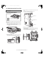
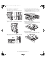
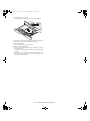
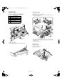
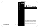
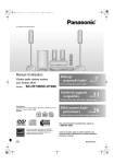
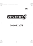
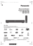
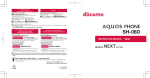
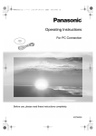
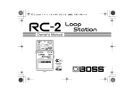
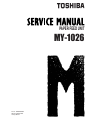
PAPER FEED UNIT
MY-1026
File No. SME04003800
R04122173900-TTEC
Ver00_2005-02
© 2005 TOSHIBA TEC CORPORATION
All rights reserved
Parts marked with “ ” are important for maintaining the safely of the machine. Be sure to replace these
parts with the replacement parts specified to maintain the safety and performance of the machine.
General Precautions for Installation/Servicing/Maintenance for the MY-1026
The installation and service should be done by a qualified service technician.
1. When installing the MY-1026 to the Equipment, be sure to follow the instructions
described in the "Unpacking/Set-Up Procedure for the MY-1026" booklet which comes
with each unit of the MY-1026.
2. The MY-1026 should be installed by an authorized/qualified person.
3. Before starting installation, servicing or maintenance work, be sure to turn OFF and
unplug the equipment first.
4. When servicing or maintaining the MY-1026, be careful about the rotating or operation
sections such as gears, pulleys, sprockets, cams, belts, etc.
5. When parts are disassembled, reassembly is basically the reverse of disassembly
unless otherwise noted in this manual or other related materials. Be careful not to
reassemble small parts such as screws, washers, pins, E-rings, toothed washers to the
wrong places.
6. Basically, the machine should not be operated with any parts removed or disassembled.
7. Delicate parts for preventing safety hazard problems (such as switches, sensors, etc. if
any) should be handled/installed/adjusted correctly.
8. Use suitable measuring instruments and tools.
9. During servicing or maintenance work, be sure to check the serial No. plate and other
cautionary labels (if any) to see if they are clean and firmly fixed. If not, take appropriate
actions.
10. The PC board must be stored in an anti-electrostatic bag and handled carefully using a
wristband, because the ICs on it may be damaged due to static electricity. Before using
the wrist band, pull out the power cord plug of the equipment and make sure that there
is no uninsulated charged objects in the vicinity.
11. For the recovery and disposal of used MY-1026, consumable parts and packing
materials, it is recommended that the relevant local regulations/rules should be
followed.
12. After completing installation, servicing and maintenance of the MY-1026, return the
MY-1026 to its original state, and check operation.
CONTENTS
[ 1 ] GENERAL ............................................................................................. 1 - 1
[ 2 ] UNPACKING AND INSTALLATION ....................................................... 2 - 1
[ 3 ] MY-1026 ................................................................................................ 3 - 1
01_GENER.fm
1 ページ
2004年12月6日 月曜日 午前10時31分
[1] GENERAL
1. Outline and specifications of each option
A. MY-1026 (250 - Sheet Paper Feed Unit)
The paper feed unit provides the convenience of increased paper
capacity for the copier and a greater choice of paper sizes readily
available for copying.
Part names
Side cover
Tray
Specifications
Copy paper size
5-1/2" × 8-1/2" to 8-1/2" × 14"
Paper weight
15 lbs. to 21 lbs.
Paper capacity
One paper tray with capacity for 250 sheets of
21 lb. bond paper
Weight
Approx. 6.6 lbs. (3 kg)
Dimensions
19.6" (W) × 15.6" (D) × 3.5" (H)
(498 mm (W) × 395 mm (D) × 88 mm (H))
Power supply
Drawn from the copier
MY-1026 GENERAL 1 - 1
02_UNPAC.fm
1 ページ
2005年1月25日 火曜日 午前10時51分
[2] UNPACKING AND INSTALLATION
The unpacking and set-up procedure shall be done by a qualified
service technician.
1. MY-1026 Installation Manual
3) Remove the OP gear cover and rubber feet from the bottom of the
copier.
Remove the screw and remove the OP gear cover.
Then, take off and remove the rubber feet.
• Parts included
Rubber foot
• Screws (M4 × 16), 4 pcs.
OP gear cover
Turn the main switch to the “OFF” position and removethe power plug
from the outlet.
1) Remove the DV cartridge and the drum cartridge from the copier.
Open the tray, the side door, and the front cabinet, and then
remove the DV cartridge and the drum cartridge.
Note: Be sure to carry out the operation in the order of (1), (2), (3),
and (4).
1
Rubber foot
4) Install the second cassette unit to the copier.
If the second cassette unit is aligned to the copier, it can be positioned automatically.
Hold the copier lightly to prevent it from toppling down and secure
the second cassette unit with four screws (M4 × 16).
4
3
2
2) Make the copier upright.
Close the front cover, side cover, and bypass tray, and then make
the copier upright in the orientation shown in the illustration.
MY-1026 UNPACKING AND INSTALLATION 2 - 1
02_UNPAC.fm
2 ページ
2004年12月6日 月曜日 午前10時31分
5) Remove the rear cover and connect the connector.
Remove the screw and remove the rear cover.
Then, connect the connector of the second cassette unit to that of
the copier.
8) Insert the drum cartridge and the DV cartridge into the copier.
Open the tray, the side door, and the front cabinet, insert the drum
cartridge and the DV cartridge, and then close the front cabinet,
the side door, and the tray.
Note: Be sure to carry out the operation in the order of (1), (2), (3),
and (4).
4
3
1
2
6) Attach the rear cover.
Attach the rear cover to its original position and secure it with the
screw (M4 × 12).
9) Remove the paper tray lock for packing.
Remove the paper tray lock for packing that secures the turning
plate in the paper tray by rotating it in the direction of the arrow and
store it in the specified position.
10) Set the paper tray side guide.
Squeeze the lever of the paper tray side guide to slide the guide to
the position for the paper size to be used.
7) Return the copier to the normal orientation.
When returning the copier to the normal orientation, gently return it
without giving a shock.
MY-1026 UNPACKING AND INSTALLATION 2 - 2
02_UNPAC.fm
3 ページ
2004年12月6日 月曜日 午前10時31分
11) Load paper into the paper tray.
When loading paper, do not exceed the maximum height line.
12) Insert the power plug into the outlet and turn the main switch to the
“ON” position. Then, perform the following procedure.
13) Perform SIM setting.
Execute simulation [26] - [3] and enter [1].
14) Check the center displacement.
Place an original on the document glass and make a copy using
the tray in the copier.
Then, make a copy using the tray in the installed optional paper
feed unit.
If the center of the copy from the optional paper feed unit is displaced from the copy from the tray in the copier, adjust the center
referring to the service manual.
MY-1026 UNPACKING AND INSTALLATION 2 - 3
03_ARD16.fm
1 ページ
2004年12月6日 月曜日 午前10時31分
[3] MY-1026
1) Open the right cabinet.
1. Disassembly and assembly
3) Remove one connector from MCU.
No.
A
2) Remove three screws.
4) While tilting down the 2nd connection arm A, pull and remove the
paper feed unit toward you.
Part name Ref.
Paper sensor
B
Cassette detection SW
C
Paper feed solenoid
D
Transport roller
E
Paper feed clutch
F
2nd paper feed roller
C
D
D
Paper feed unit removal
1)
1)
2
4
3
B
1
A
1)
2)
2
1)
* When installing, securely insert two bosses C on the machine side
and two bosses D on the paper feed unit side. Be sure to secure the
ground wire B.
* Insert the 2nd page feed.
1) Remove the screw.
2) Remove the rear cover.
*
When installing, engage the pawl and install the unit.
A. Paper sensor
1) Remove the pawl.
2) Remove the paper sensor.
3) Remove the harness.
2
3
2
1
A
1
MY-1026 3 - 1
03_ARD16.fm
2 ページ
2004年12月6日 月曜日 午前10時31分
B. Cassette detection switch
E. Paper feed clutch
1) Remove the pawl.
1) Remove the E-ring.
2) Remove the cassette detection switch.
2) Remove the paper feed clutch.
3) Remove the harness.
3) Remove the parts.
1
A
2
3
1
2
3
C. Paper feed solenoid
1) Remove the screw.
2) Remove the connector.
3) Remove the paper feed solenoid.
2
3
* When installing, fit the cut surface A.
F. 2nd paper feed roller
1) Remove the E-ring and the parts.
2) Remove the 2nd paper feed roller.
A
1
1
D. Transport roller
B
1) Remove two E-rings.
2) Remove the transport roller.
2
4
1
C
1
D
B
A
3
* When installing, hang the 2nd connection arm on the 2nd
connection arm Spring B. Be sure to install so that the earth spring
C is in contact under the bearing D.
2
* Install so that the earth spring A is brought into contact over bearing
B.
MY-1026 3 - 2
COVER4.fm
1 ページ
2004年12月6日 月曜日 午前10時32分
CAUTION FOR BATTERY DISPOSAL
(For USA,CANADA)
Contains lithium-ion battery. Must be disposed of properly.
Remove the battery from the product and contact
federal or state environmental
agencies for information on recycling and disposal options.
COVER4.fm
2 ページ
2004年12月6日 月曜日 午前10時32分
Trademark acknowledgments
Windows and Windows NT are trademarks of Microsoft Corporation in the U.S.A.
and other countries.
IBM and PC/AT are trademarks of International Business Machines Corporation.
PCL is a trademark of Hewlett-Packard Company.
Pentium is a registered trademark of Intel Corporation.
All other trademarks and copyrights are the property of their respective owners.
2-17-2, HIGASHIGOTANDA, SHINAGAWA-KU, TOKYO, 141-8664, JAPAN