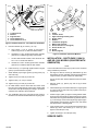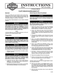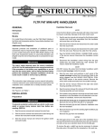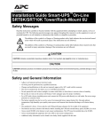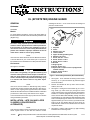
1
-J01290
REV. 2013-11-01
XL (SPORTSTER) ENGINE GUARD
Installing the 3/8-24 x 1-1/4 in. screws from kit will damage nut
plate and screw threads.
GENERAL
Kit Number
49018-88C
is08497
Models
4
For model fitment information, see the P&A retail catalog or
the Parts and Accessories section of www.harley-davidson.com
(English only).
3
5
1
2
The rider's safety depends upon the correct installation
of this kit. Use the appropriate service manual procedures.
If the procedure is not within your capabilities or you do
not have the correct tools, have a Harley-Davidson dealer
perform the installation. Improper installation of this kit
could result in death or serious injury. (00333a)
1.
2.
3.
4.
5.
6.
7.
8.
9.
10.
11.
12.
13.
Nut plate
Frame
Washer, 3/8 in. flat
Locknut, 3/8-24
Upper mounting bracket guard
Washer, 5/16 in. flat
Screw, 5/16-18 x 1-1/2 in
Screw, 3/8-24 x 1-1/4 in.
Screw, 3/8-16 x 1-3/4 in.
Bracket
Engine guard
Screw, 3/8-24 x 5 in.
Spacer, 3/4 x 1/8 (Do not use if equipped with
forward controls)
14. Screw, 3/8-24 x 5-1/2 in.
15. Motor mounts
NOTE
This instruction sheet references Service Manual information.
A Service Manual for your model motorcycle is required for
this installation and is available from a Harley-Davidson Dealer.
Kit Contents
See Figure 4 and Table 1.
Front and/or rear guard(s) can provide limited leg and
cosmetic vehicle protection under unique circumstances.
(Fall over while stopped, very slow speed slide.) It is not
made or intended to provide protection from bodily injury
in a collision with another vehicle or any other object.
(00022b)
NOTE
This kit can also be installed on 1982 through early 1984 XL
and XR-1000 models (equipped with generator) with the purchase of short engine guard support bracket, Part Number
49014-85. Part 49014-85 is not included with this kit. Installation
procedures for 1982 to early 1984 vehicles are on Page 2.
Figure 1. Disassembly/Installation (Alternator Models)
1.
See Figure 1. From underside of steering head remove
screws (7, 8, or 9) and flat washer (6). Discard original
screws and washer.
2.
Remove and discard the two top motor mount screws,
washers, and nuts.
3.
See Figure 1 and Figure 2. Place washer (3) on 5-1/2 in.
long screw (14). Insert screw (14) through one motor
mount, through spacer (13) (unless engine guard is being
installed on a vehicle equipped with forward controls, in
which case DO NOT USE SPACER), through the offset
end of bracket (10), and (with large offset toward jiffy stand
side of vehicle) through the other motor mount. Place kit
supplied washer (3) on end of screw (14) and secure with
locknut (4). Be sure bracket does not pinch wiring. On
1986 and later models be sure bracket does not contact
oil pressure switch.
4.
See Figure 1. Position engine guard (11) upper mounting
bracket under the steering head.
Cover front fender with a clean rag to protect it from scratches
during installation procedures.
INSTALLATION - LATE 1984 AND LATER
XL MODELS (EQUIPPED WITH
ALTERNATOR)
NOTE
Late 1994 and 1995 XL vehicle nut plates have 3/8-16 threads.
Reuse original screws on late 1994 and 1995 XL models.
-J01290
Many Harley-Davidson® Parts & Accessories are made of plastics and metals which can be recycled.
Please dispose of materials responsibly.
1 of 3
is08105
is08106
10
14
3
1
12
4
2
7
6
8
4
11
1.
2.
3.
4.
5.
11
Locknut, 3/8-24
Bracket
Engine Guard
Screw, 3/8-24 x 5 in.
Screw, 3/8-24 x 5 1/2 in.
1.
2.
3.
4.
5.
6.
7.
8.
9.
10.
11.
Figure 2. Hardware Positions - Late 1984 and Later Models
5.
Place flat washers (6) on screws (7, 8, or 9):
a.
Use 5/16-18 x 1-1/2 in. screws (7) and 5/16 in.
washers (6) from kit on 1985 and earlier models.
b.
Use 3/8-24 x 1-1/4 in. screws (8) and 5/16 in. washers
(6) from kit on 1986 through early 1994 models.
c.
On late 1994 and later models, reuse the stock 3/816 x 1-1/4 in. screws and washers.
d.
Use 3/8-16 x 1-3/4 in. screws (9) and 5/16 in. washers
(6) from kit on 1996 and later XL 883 models.
10
2
5
9
Frame
Locknut, 3/8-24
Upper mounting bracket guard
Engine guard
Bracket
Lockwasher (original)
Washer, flat (original)
Screw, 5/16-18 x 1-1/2 (original)
Screw, 3/8-24 x 5 in.
Spacer
Screw (original)
Figure 3. Installation (Generator Models)
INSTALLATION - 1982 TO EARLY 1984 XL
AND XR- 1000 MODELS (EQUIPPED WITH
GENERATOR)
NOTE
6.
Insert screws (7, 8, or 9) through upper bracket on engine
guard (11) and thread into nut plate.
Cover front fender with a clean rag to protect it from scratches
during installation procedures.
7.
Attach bracket (10) to engine guard (11) using screw (12)
and locknut (4).
1.
8.
Tighten nut (4) on screw (12) to 33 ft-lbs.
9.
Tighten screw (7, 8, or 9) to 19 ft-lbs.
See Figure 3. Remove screws (8), lockwashers (6), and
flat washers (6) from underside of steering head. Discard
original screws (7). Retain washers for reassembly.
Do not remove shim washers between frame and motor
bracket.
10. Tighten nut (4) on screw (14) to 33 ft-lbs.
2.
11. On 1986 models, remove clutch cable from clutch hand
lever and route cable through engine guard. Install cable
at hand lever and adjust freeplay according to procedure
outlined in the 1986 XLH Service Manual.
Remove screw (11), spacer (10), and nut (2) at frame
downtubes.
3.
Attach bracket (5), Part number 49014-85, to engine guard
(4) using screw (9) and locknut (2). Tighten screw (9) to
33 ft-lbs (44.7 Nm).
12. Turn handlebars fully to the right and left and check for
interference of clutch and brake cables from engine guard.
4.
Position engine guard (3) upper mounting bracket under
steering head, with bracket (4) aligned with holes in frame
downtube. Place original lockwashers (6) and flat washers
(7) on screws (8). Insert screws (8) through upper engine
guard bracket, through upper engine mount, and thread
into tapped holes in steering head.
5.
Insert original screw (11) through frame downtubes and
bracket (5). Place new locknut (2) on screw (11) and
tighten to 33 ft-lbs (44.7 Nm).
6.
Tighten screws (8) to 19 ft-lbs (25.7 Nm).
SERVICE PARTS
-J01290
2 of 3
is08107
2
1
8
9 10
7
3
6
5
4
Figure 4. Service Parts
Table 1. Service Parts
Item
Description (Quantity)
Part Number
1
Engine guard
2
Washer, 5/16 x 15/16 x 3/16 (2) 6336B
3
Screw, 3/8-24 x 5-1/2 in.
4413
4
Locknut, 3/8-24 x7/16 x 9/16
7775
5
Bracket
49014-86A
6
Screw, 3/8-24 x 5 in.
4333
7
Spacer, 3/4 x 1/8
5789
8
Screw, 5/16-18 x 1-1/2 in. (2)
4816A
9
Screw, 5/16-24 x 1-1/4 in. (2)
45999-81A
10
Screw, 3/8-16 x 1-3/4 in. (2)
3554
11
Washer, 3/8 x 13/16 x 5/32 (Not 6474
Shown)
-J01290
3 of 3