1
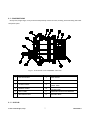
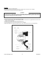
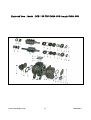
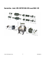
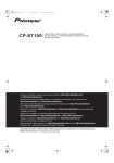
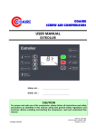
Authorized Distributor Only
ROTARY SCREW AIR-END
MAINTENANCE MANUAL AND PARTS LIST
MODEL
BCS-130 FOR CHSA-20/25/30
BCS-168 FOR CHSA-50/75/100
168 FOR CHSA-50/75/100
COAIRE TECHNOLOGIES, CORPORATION
All rights reserved
Printed in U.S.A.
For proper and safe use of the compressor, please follow all instructions and safety precautions as identified in
this manual, along with general safety regulations and practices.
SAFETY AND PRECAUTIONS
Before you install the air compressor you should take the time to carefully read all the instructions
contained in this manual. Electricity and compressed air have the potential to cause severe personal
injury or property damage. Before installing, wiring, starting, operating or making any adjustments,
identify the components of the air compressor using this manual as a guide. The operator should use
common sense and good working practices while operating and maintaining this unit. Follow all
procedures and piping accurately. Understand the starting and stopping sequences. Check the safety
devices in accordance with the following procedures contained in this manual. Maintenance should be
done by qualified personnel, accurately with proper tools. Follow the maintenance schedule as
outlined in the manual to ensure problem free operation after start up.
SAFETY PRECAUTIONS
BEFORE INSTALLING THE COMPRESSOR OR PERFORMING ANY MAINTENANCE READ THIS MANUAL
CAREFULLY.
WARNINGS
COMPRESSED AIR AND ELECTRICITY ARE DANGEROUS. BEFORE DOING ANY WORK ON THIS UNIT, BE SURE THE
ELECTRICAL SUPPLY HAS BEEN SHUT OFF(LOCKED AND TAGGED) AND THE ENTIRE COMPRESSOR SYSTEM HAS
BEEN VENTED OF ALL PRESSURE.
1. Do not remove the cover, loosen or remove any fittings, connections or devices when this unit is
operating or in operation. Hot liquid and air that are contained within this unit under pressure can cause
severe injury or death.
2. The compressor has high and dangerous voltage in the motor, the starter and control box. All
installations must be in accordance with recognized electrical procedure. Before working on the
electrical system, ensure that the system's power has been shut off by use of a manual disconnect
switch. A circuit breaker or fuse switch must be provided in the electrical supply line to be connected to
the compressor. The preparation work for installation of this unit must be done in suitable grounds,
maintenance clearance and lighting arrestors for all electrical components.
3. Do not operate the compressor at a higher discharge pressure than those specified on the compressor
nameplate. If so an overload will occur. This condition will result in electric motor compressor
shutdown.
4. Use only safety solvent for cleaning the compressor and auxiliary equipment.
5. Install a manual shut off valve(isolation type) in the discharge line for service work.
6. Whenever pressure is released through the safety valve during operation, it is due to excessive pressure
in the system. The cause of excessive pressure should be checked and immediately corrected.
7. Before doing any mechanical work on the compressor,
a) Shut down the unit.
b) Electrically isolate the compressor by use of the manual disconnect switch in the power line to the
unit. Lock and tag the switch so that it cannot be operated.
c) Release all compressed air within the system and isolate the unit from any other sources of air.
8. Allowing the unit lubricants to enter into the plant air system must be avoided at all times. Air line
separators, which are properly selected and installed, can reduce any liquid carry-over close to zero.
9. Before starting the compressor, the maintenance instructions should be thoroughly read and understood.
10. After maintenance work is completed, covers must be securely closed.
11. For questions contact your distributor before proceeding.
Coaire Technologies, Corp.
1
CHSA-M0211
STATEMENT OF WARRANTY TERMS & CONDITIONS
COAIRE’s screw air compressors are warranted to be free of defects in materials and workmanship under proper use,
installation, and application. This warranty shall be for a period of 15 months from date of shipment from our factory or other
stocking facilities or 12 months from date of installation. Proof of installation date will be required. All air compressors outside
the U.S. and Canada carry a parts only warranty.
ALL FREIGHT DAMAGE CLAIMS ARE NOT THE RESPONSIBILITY OF THE MANUFACTURER AND ARE NOT
COVERED UNDER WARRANTY AS ALL PRODUCTS ARE SHIPPED F.O.B. SHIPPER.
PLEASE DIRECT ALL FREIGHT CLAIMS TO THE SHIPPER IN QUESTION.
MAINTENANCE AND ADJUSTMENTS
ADJUSTMENTS TO THE HOT GAS AND MAINTENANCE OF FLOAT AND AUTOMATIC DRAINS AND CONDENSER
COILS ARE CONSIDERED TO BE ROUTINE MAINTENANCE AND THEREFORE NON-WARRANTABLE ITEMS AND
ARE THE SOLE RESPONSIBILITY OF THE END USER. CONSULT THE INSTALLATION, OPERATION AND
MAINTENANCE MANUAL FOR THE ADJUSTMENT AND MAINTENANCE PROCEDURES.
This warranty does not apply to any unit damaged by accident, modification, misuse, negligence, or misapplication. Damage
to heat exchangers by exposure to ammonia, any other corrosive substance or sub-freezing environment will be considered
misuse.
Any air compressors part or material found defective will be repaired, replaced or refunded, at the sellers option free of charge,
provided that COAIRE is notified within the above stated warranty period. All returns of allegedly defective equipment
must have prior written authorization. Said authorization may be obtained through our air compressor service department.
All air compressors, parts, materials must be returned freight prepaid to the Manufacturer’s factory within 30 days of return
authorization date. Any shipment returned to the factory collect will be refused.
If an item is found to be warrantable, the repaired item or replacement will be returned normal ground freight prepaid within the
continental United States and Canada. Expedited shipment costs are the responsibility of the requestor.
Any replacement part or material is warranted only to the extent of the remaining warranty period of the dryer or to the extent as
provided by the supplier, whichever is longer.
Identification Plate
The identification plate is located on the side of the air compressor and shows all the primary data of the machine. Upon
installation, fill in the table on the previous page with all the data shown on the identification plate. This data should always be
referred to when calling the manufacturer or distributor.
The removal or alteration of the identification plate will void the warranty rights.
DISCLAIMER
The warranty does not cover any responsibility or liability for direct or indirect damages to persons, or equipment caused by
improper usage or maintenance, and is limited to manufacturing defects only. Refer to COAIRE Warranty policy manual for
travel, mileage and special charge considerations. The warranty will be immediately voided if there are changes or alterations
to the dryer.
WHO TO CONTACT IF YOU HAVE A WARRANTY CLAIM:
COAIRE Technologies, Corporation
Phone
(562) 463-3935
Fax
(562) 463-4928
All freight damage claims should be filed within 15 working days and should be directed to the carrier.
Coaire Technologies, Corp.
2
CHSA-M0211
SAFETY AND PRECAUTIONS
STATEMENT OF WARRANTY TERMS AND CONDITIONS
TABLE OF CONTENTS
Chapter Ⅰ. General information
1-1.
Scope ......................................................................................................................
..................
1-2. Compression
process ............................................................................................................
1-3. Oil
flow ........................................................................................................................
............
1-4.
Features ...................................................................................................................
...............
Chapter Ⅱ. Functional descriptions
2-1.
Constructions .............................................................................................................
............
2-2.
Drive .......................................................................................................................
.................
2-3. Capacity
control ....................................................................................................................
Chapter Ⅲ. Scheduled maintenance
3-1. Maintenance
scheduled ........................................................................................................
3-2. Control of
lubrication ............................................................................................................
3-3. Standard overhaul
period .....................................................................................................
3-4. Component replacement
guide ..........................................................................................
3-5. Standard
specifications .........................................................................................................
Chapter Ⅳ. Disassembly
4-1. Preparation for
overhaul .......................................................................................................
4-2. Disassembly for
air-end ..........................................................................................................
4-3. Seal
cover .......................................................................................................................
..........
4-4. Outlet bearing
cover ..............................................................................................................
4-5. Outlet
casing ......................................................................................................................
......
4-6. Outlet casing and
bearings ....................................................................................................
4-7. Screw
rotor .......................................................................................................................
.......
4-8. Suction side
bearing ...............................................................................................................
4-9. Inner ring of roller
bearing ...................................................................................................
Coaire Technologies, Corp.
3
4
4
5
5
6
7
8
9
10
12
13
14
15
15
16
16
18
18
20
20
20
CHSA-M0211
Chapter Ⅴ. Reassembly
5-1.
Preparation ...............................................................................................................
...............
5-2.
Cleaning ...................................................................................................................
.................
5-3. Suction side
bearing ...............................................................................................................
5-2.
Cleaning ...................................................................................................................
.................
Appendix
A. Exploded view for
BCS-130 ........................................................................................................
B. Exploded view for
BCS-168.........................................................................................................
Coaire Technologies, Corp.
4
22
22
24
22
34
36
CHSA-M0211
CHAPTER Ⅰ. GENERAL INFORMATION
1-1. SCOPE
This manual shall be applied to air end models for COAIRE screw Air End as follows. ; BCS-130, BCS-168. Screw
Air End driven by an electric motor is the important part of screw air compressor unit. It is single stage, oil
injected, rotary screw type. Screw Air End have been developed to meet higher performance including high
efficiency, high reliability, low noise and low vibration, and have been introduced to the market since 1988 with
our long manufacturing experiences.
1-2. COMPRESSION PROCESS
Air flows through an air intake filter, intake silencer and suction control valve to the air end suction port. Air
then is compressed by the rotation of the male rotor, and oil is injected into the Air End during compression
process. The injected oil performs various functions, such as, sealing, cooling as well as lubricating. The air/oil
mixture leaves the air end through the discharge port.
Fig 1-1. Suction Process
Fig 1-2. Compression Process
Fig 1-3. Oil Injection Process
Fig 1-4. Discharge Process
1-2-1. SUCTION PROCESS.
Coaire Technologies, Corp.
5
CHSA-M0211
Along with the rotation of the rotor, air is admitted fully into the void of two rotors through the suction port.
The void is then isolated from the suction port with the casing wall, thereby completing the suction process.
1-2-2. COMPRESSION PROCESS.
The air in the void is compressed by meshes between the male rotor and the female rotor lobes and squeezes
the air against discharge cover.
1-2-3. OIL INJECTION PROCESS.
As pressure builds, oil is injected into the compression area and onto the bearings and shaft seal, serving to
lubricate, absorb compression heat and seal the rotors.
1-2-4. DISCHARGE PROCESS.
Compression continues as the rotor rotates. When the void comes to the discharge port provided in the
discharge chamber, the compressed air is discharged through the port. While this process is occurring with one
inter-lobe space, the other spaces are following the same cycle. Therefore air is continuously compressed.
1-3. OIL FLOW
The oil which is collected in the oil sump at the bottom of the oil separator is circulated through the lubrication
system by the pressure differential existing between the oil separator and the air end. Oil injected via the
internal oil hole is provided into the intermesh among male rotor, female rotor and the rotor casing, the shaft
seal, suction side and discharge side bearings.
1-4. FEATURES
1-4-1. Precision grind rotors provide close inter-lobe clearance. This minimizes leakage and increases
efficiency.
1-4-2. Long service life and high reliability of bearings achieved by application of 5+7 and 4+6 profile rotors. At
the discharge end of the Air End, double angular contact ball bearings for the male and female rotors are
located to support axial thrust loads and to position the rotor. Cylindrical roller bearings are also located to
support radial loads.
1-4-3. With a differential pressure lubrication system, the Air End can dispense with an oil pump, thus
dramatically simplifying the oil supply system.
1-4-4. The wedge construction of the secondary sealing element of the mechanical seal naturally eliminates
leakage. This seal is highly reliable and excellent performance.
CHAPTER Ⅱ. FUNCTIONAL DESCRIPTIONS
Coaire Technologies, Corp.
6
CHSA-M0211
2-1. CONSTRUCTIONS
Oil injected, single stage, rotary screw Air End primarily consists of rotors, housing, shaft seal along with other
component parts.
Fig 2-1. Cross Section of Air end(Model : BCS-130)
NO.
NAME
NO.
NAME
1
ROTOR HOUSING
7
MALE ROTOR
2
INLET CASING
8
FEMALE ROTOR
3
OUTLET CASING
9
4
BEARING COVER
10
5
SEAL COVER
11
ANGULAR CONTACT BALL BEARING
6
MECHANICAL SEAL
12
DISTANCE RING
CYLINDRICAL ROLLER BEARING
(INLET SIDE)
CYLINDRICAL ROLLER BEARING
(OUTLET SIDE)
2-1-1. ROTORS
Coaire Technologies, Corp.
7
CHSA-M0211
With high-precision and high-grade finishing rotors, mechanical vibration sources have been eliminated, thus
ensuring smooth and quiet operation. The lobe combinations are two types. In case of model BCS-130, the lobe
combinations of male and female rotors have 5+7 rotor profile. In case of model BCS-168, the lobe combinations
of male and female rotors have 5+7 profile.
Fig 2-2. Newly-Developed 5+7 Profile Screw Rotors
2-1-2. HOUSING
Screw air end incorporates the low noise design with double housing construction. With this design, the noisy
male rotor is located at the center of double housing minimizing the noise liable to occur during low
temperature operation. The cylindrical roller bearings support the radial loads, whereas the angular ball
bearings support the axial loads.
2-1-3. SHAFT SEAL
Mechanical seal is fitted on the male rotor shaft to prevent oil and air leakage.
2-1-4. BEARINGS
At the discharge end(the outlet casing) of the Air End, double angular contact ball bearings and a cylindrical
roller bearing for the male rotor and the female rotor are located to support axial thrust loads and radial
loads. Moreover, the springs for reducing the axial loads is located, assuring long life and high reliability. Oil
for lubrication is supplied to each bearing by the pressure difference without oil pump.
2-2. DRIVE
2-2-1. V-BELT DRIVE(Fig. 2-3)
Motor speed is increased by V-belt drive to the male rotor's driving speed.
2-2-2. COUPLING DRIVE(Fig. 2-4)
Motor speed is transferred by coupling drive to the male rotor's driving speed.
Coaire Technologies, Corp.
8
CHSA-M0211
Fig 2-3. V-Belt drive
Fig 2-4. Coupling drive
2-3. CAPACITY CONTROL.
All models provide capacity control, on-line/off-line control with upper range modulation. Internal pressure is
vented to atmosphere at partially loaded or unload conditions whereby the motor idles for power saving
features.
Coaire Technologies, Corp.
9
CHSA-M0211
CHAPTER Ⅲ. SCHEDULED MAINTENANCE
3-1. STANDARD MAINTENANCE SCHEDULE
The maintenance of the air compressor unit equipped with these screw air end should be performed based on the following
standard maintenance schedule. The intervals are a guide based on normal operating conditions. If operated in a severe
environment, necessary maintenance service should be performed on a more frequent basis. User should carry out the
maintenance work, based on either the running hours or the calendar time whichever comes first. Please be advised that
Items marked with ○ should be performed by a user while the other marked with ● should be maintained, by an authorized
distributor.
Part
Indication of control
panel
Condensation from oil
separator
Oil level
Action
taken
Check
Daily
Monthly
Maintenance Interval
6 Monthly
Annually
500 Hrs
3000 Hrs
6K HRS
2 yearly
12K HRS
Drain out
○
Check
○
1st check
only
○
Clean
○
Oil filter element
Replace
Oil scavenge filter
Clean
○
○
Oil(recommended
Replace
○
Oil scavenge filter
Clean
○
Oil level gauge
Clean
○
Mechanical seal
Check for
leak
○
Oil filter element
Replace
○
Oil scavenge filter
Replace
●
Suction throttle valve
Clean
●
Gasket(Suction control
valve)
Replace
●
V-belt/Coupling
Replace
●
Air-end gasket and
o-ring
Check &
Replace
●
Air end(Bearing &
Mech. Seal)
Replace
Suction filter
Remark
24K Hrs
○
Replace
Oil(recommended
brands)
4 yearly
Subsequent
brands)
replace
Coaire Technologies, Corp.
●
10
CHSA-M0211
3-2. CONTROL OF LUBRICATION
The control of lubrication is critical. Neglecting it may cause varnish or sludge deposits in the system, resulting
in severe damage or breakdown of the unit. The major causes of such deposits are :
⑴ Mixing of different types or brands of oil.
⑵ Use of unsuitable oil.
⑶ Failure to drain the condensation, which will result in an oil deterioration.
⑷ Failure to change oil within a scheduled maintenance interval.
WARNING
Use of inappropriate oil and/or improper maintenance may result in catastrophic
damage to the air compressor or may result in a oil separator element fire.
CONSULT YOUR DISTRIBUTOR FOR MAINTENANCE SERVICE AND COLUBE 68 COMPRESSOR
OIL.
3-2-1. FUNCTIONS OF OIL
Oil is an essential factor in the oil flooded rotary screw compressor. Use COAIRE COLUBE 68 only, which is
developed for pressurized circulation system, containing rust, foam, oxidation and wear inhibitors along with
effective water release characteristics. Oil performs the following functions :
① Lubrication : Oil lubricates the bearing and other internal components.
② Sealing : Oil seals the clearance between the two rotors and clearance between the rotors and inner wall of
casing. This prevents air leakage above the inter mesh during compression to increase compression process
efficiency.
③ Cooling : Oil is injected during compression process to remove the heat of compression.
WARNING
Never mix different brands or types of oils each other. Blending of oils may cause a
formation of varnish or sludge deposits in the system. If oils have been carelessly mixed or if
a certain brand of oil must be replaced with another, be sure to flush out the oil system first.
Consult your distributor for the procedures. We highly recommended the use of Genuine
COAIRE Screw Compressor Oil COAIRE-COLUBE 68.
3-2-2. OIL CHANGE
A practical way is to change the oil at the following intervals :
① First oil change : 500 hours after initial start-up.
② Second oil change : 1,500 hours after the first oil change.(4,000 hours after the initial start-up)
Coaire Technologies, Corp.
11
CHSA-M0211
③ Third and consequent oil changes : Every 4,000 hours after the previous oil change.
The above intervals are based on normal operating conditions. If condensation is not drained from the unit,
the oil will be deteriorated and required more frequent oil changes. Proceed as follows :
① Run the unit loaded mode long enough to have the oil warm up.
② Stop the unit, confirm that the pressure has been released completely, and close the isolation stop valve at
the discharge outlet and disconnect the main electrical.
③ Place a drain pan under the oil drain valve of the unit, and open the valve. Open the plug of oil filling port on
oil separator to speed up draining.
④ For draining the oil cooler, remove the plug at the drain outlet of the oil cooler to let the oil run down.
⑤ Drain the oil as completely as possible. Then, close the drain valve of oil separator and drain plug of oil cooler.
Return the plug to the drain outlet and tighten.
⑥ Fill with new oil through the oil filling port of oil separator. Refer to the specification table for appropriate
oil amount.
⑦ After securely tightening the plug at the oil filling port, run the unit to make sure there are no oil leaks.
3-2-3. DRAINING CONDENSATION
Moisture contained in intake air can be condensed into water during long unloading time or when the unit is
stopped, and this moisture is accumulates in the separator sump, Since the water in a compressor system can
cause deterioration of oil and internal rusting, do not neglect draining the condensation at least on a daily basis.
Draining should be performed before start-up since oil and condensation have been sufficiently separated from
each other. Open the drain valve at outlet of oil separator sump. Use a pan to store the condensation being
drained. Closely watch the draining condensation, and close the valve.
WARNING
Even if the unit is in 24 hour continuous service, it is still recommended to perform a draining
procedure. Normally in such an operation mode, an extra stand-by compressor has to be
installed at the same time to allow for better draining of condensation.
Coaire Technologies, Corp.
12
CHSA-M0211
NOTE
If a compressor operation can be suspended (for example, during lunch time), it is a wise
practice to drain the condensate once again after the suspension time. Thirty(30) minutes
may be enough for sufficient separation of oil from condensation.
CAUTION
LUBRICANT
Avoid prolonged breathing of vapors. Always use adequate ventilation, contact with eyes
should be avoided. Avoid prolonged periods of skin contact.
If excessive vapors are inhaled, remove person to fresh air area. In the event of contact
with eyes, flush with water and consult a physician if serious irritation persists.
In the event of contact with skin, wash contacted area with soap and water. Wash clothing
before reusing.
Contents will burn. Use water fog, foam, dry chemical or carbon dioxide to extinguish.
Avoid use of direct stream of water since product may float and reignite.
Dispose of oil by using an recycling service. Do not dump oil into drain or onto the ground.
Do not place oil or partially filled oil containers in trash. Keep out of sewers and water
systems
3-3. STANDARD OVERHAUL PERIOD
When the periodic checking and inspections mentioned on the previous page are appropriately performed and
the Air Ends have been operated under normal conditions, the Air Ends should be overhauled according to the
following guide :
Overhaul the screw Air Ends within the following years of operation hours which ever case first occurs :
⑴ Ever five years from the date of starting operation
⑵ Every 20,000 operation hours for applications to air-cooled units or every 30,000 operation hours for
applications of water-cooled units.
Note
The purpose of the overhauling is to exchange roller bearings and ball bearings with new ones. The exchange of
gaskets, O-rings and oil are also required.
3-4. COMPONENT REPLACEMENT GUIDE
Coaire Technologies, Corp.
13
CHSA-M0211
3-4-1. Components to be replaced
Securely replace the following components when the screw Air Ends are overhauled.
Name of Component
Item Number(BCS-130)
Item Number(BCS-168)
Cylindrical Roller Bearing
11, 12, 13
12, 13, 14
Angular Contact Ball Bearing
14
15
Adjusting Washer
9
10
Gasket
16, 17
17, 18, 19, 20
O-Ring
28
31
Wave Spring
8
9
Cup Spring
24
27
Washer
27
30
3-4-2. Inspection and Replacement of Components
Check the following components and exchange them with new ones, if required.
Name of Component
Item Number(BCS-130)
Item Number(BCS-168)
4
5
Male Rotor
Female Rotor
5
6
Mechanical Seal
15
16
3-4-3. Screw Rotors
Basically, it is not recommended that the male screw rotors and the female screw rotors be exchanged with
new ones. However, in order to maintain the screw compressor's performance including capacity, suppression of
noise and vibration, the replacement of the screw rotors can be performed according to the following guide.
A file or rough sand paper must not touch the surfaces of the screw rotors. However, the small scratches can be
required with an oilstone or #280 sand paper.
3-4-4. Mechanical Seal
Mechanical seal is located on the suction side of male rotor shaft. The contact surfaces are lubricated by oil
which is fed through a port in the oil seal housing. The drain tube for this oil is routed back to the air intake via
a check valve. This system must be inspected, cleaned or replaced if necessary every 3000 operating hours or
every 3 months whichever comes first. Oil seal wear may be monitored/tested. Maximum oil leakage 3 cc/h.
Consult your distributor.
Coaire Technologies, Corp.
14
CHSA-M0211
CAUTION
Do not install anything to block the drain tube, such as a stop valve. The drain tube should
be open to the atmosphere in order to check for the mount oil leak, in the event of such
incident.
3-5. STANDARD SPECIFICATIONS
Type
Unit
BCS-130
BCS-168
Power source size @ 125 psig
kW
15 - 29
35 – 89
Capacity @ 125 psig
scfm
72 - 160
195 - 495
Max. Operating Pressure
psig
190
190
Rotor speed @ 125 psig
RPM
2200 - 4400
1500 - 4000
Rotor Diameter
Male
mm
130
168.23
Female
mm
126.88
168.23
Rotor Length
mm
150
281
Center Distance
mm
104
132
-
1.154
1.670
L/Dm
Displacement Volume
cb.in./rev.
68.7
234.8
Lobe Combination, M/F
-
5/7
4/6
Driven By(rotor)
-
male
Male
Suction size, Bore
inch
3-9/64
7-7/8
Discharge size, Bore
inch
1-37/64
2-3/4
lbs
203
474
Weight
Coaire Technologies, Corp.
15
CHSA-M0211
CHAPTER IV. DISASSEMBLY
4.1. PREPARATION FOR OVERHAUL
Thoroughly perform the following preparation work before starting the overhauling work of the air-ends.
4.1.1. Air-ends
According to the procedures indicated in the instructions of the unit, remove the unit, remove the air-end to
be overhauled from the unit. Observe the following air-end handling rules:
① The air-end must not be left flange open for longer than 24 hours.
② If the air-end is required to be left open for longer than 24 hours, close the covers of the air-end to avoid rust
and dust accumulation, and dip the parts of the air-end in oil.
③ If the air-end is required to be left open for longer than one week before the next procedures into the air-end,
dehydrate the air-end.
④ Oil remains in the screw air-end.
⑤ The air-end has been placed on the workbench.
4.1.2. Location and Facility
The location where the overhauling work of the air-end is performed should be clean, clear, dry and be
provided with a wide service space. The necessary facilities for the overhauling work of the air-end are listed in
this manual.
4.1.3. General Tools, special Jigs and Replacement parts
Prepare general tools, special jigs, necessary spare parts and materials in accordance with the lists in this
service manual. The general tools, special tools and materials which are necessary for the overhauling work are
listed in this manual. The necessary spare parts are listed in this manual, maintenance guide.
4.1.4. Tightening Torque List
Tighten the bolts and nuts in the screw compressor, according to the following tightening torque standard.
Name
Socket Head Bolt
Lock Nut
M8
450
-
M10
800
-
M12
-
M14
-
M16
-
M35
2200
M45
2800
M50
3000
4.2. DISASSEMBLY FOR AIR END
All the parts of the air-end must be reassembled to the same locations of the air-end as before disassembly,
excluding consumption articles such as gaskets, oil and replacement parts which are indicated in the
maintenance guide. Therefore, in order to avoid confusion, all covers and casings must be marked with a
marking pen and all disassembled parts must be positioned on a clean sheet of paper or cloth in the order of
disassembly. This service manual has been complied for the overhauling work of screw air-end, model
CHSA-20S~30S. This air-end must be brought into the workshop. After pumping down or purging compressed air
from the receiver, remove the screw air-end from the unit according to the following procedures.
Coaire Technologies, Corp.
16
CHSA-M0211
① Check to ensure that the pressure in the screw air compressor unit is near to zero in gauge pressure, and then
purge compressed air from the receiver.
② Disconnect all electric wiring.
③ Loosen the suction and discharge piping connections and check to confirm that the pressure of the connection
part is zero in gauge pressure, then disconnect all the piping.
④ Remove the V-Belt from motor shaft and air end rotor shaft.
⑤ Lift the air end utilizing wire rope. The weight of the screw air end is shown in the below table.
Air End Model
BCS-130
BCS-168
Weight(kg)
90
208
4.3. SEALCOVER AND OIL SEAL
Required Tools : 8 mm Hexagon Wrench
2,500kg-cm Torque Wrench
Plastic Hammer
Procedure
① Loosen all M10 hexagon socket bolts(28) with 8mm hexagon wrench.
② Remove the bolts(28), the seal cover(1) and the gasket(27).
③ Remove the female suction sleeve(15) and the wave spring(14)
④ Remove the mechanical seal(16)
Fig 2-3. Oil seal
CAUTION
Be careful not to scratch or damage the air-end shaft.
Coaire Technologies, Corp.
17
CHSA-M0211
4.4. OUTLET BEARING COVER & LOCK NUT/WASHER
Required Tools : 8 mm Hexagon Wrench
Rotor Stopper Jig
Bearing Lock Nut Jig
2,500kg-cm Torque Wrench
Flat Head Screwdriver
Plastic Hammer
Procedure
① Loosen all M10 hexagon socket bolts(20) with 8mm hexagon wrench.
② Remove the bolts(20), the outlet bearing cover(6) and the gasket(17).
③ Remove the female and male cup springs(24)
④ Remove the bolts(18), the washers(27), sleeves(10) and spring pins(25) from the both sides of the male &
female screw rotors.
⑤ Release lock washers(23) from the both sides of the male and female screw rotors with a flat head screw
driver.
⑥ Remove lock washers(23).
⑦ Insert the rotor stopper jig to the shaft end of male screw rotor(4) and fix the screw rotors to prevent rotation
with M12 bolt.
⑧ Attach the bearing lock nut jig to the groove of lock nuts(22). Then, insert a 2,500 kg-cm torque wrench into
the square hole of the jig and loosen lock nuts(22).
⑨ Remove lock nuts(22) by hand.
⑩ Remove the rotor stopper jig.
Coaire Technologies, Corp.
18
CHSA-M0211
4.5. OUTLET CASING
Required Tools : Bearing Removal Jig 1
Bearing Removal Jig 2
Dowel Pin Removal Jig
14mm Hexagon Wrench 300mm Length
Adjustable Wrench 300mm Length
Procedure
① Loosen M10 hexagon socket bolts(21) with a 8mm hexagon wrench and remove the bolts by hand.
② Remove the dowel pins(26) with dowel pin removal jig.
③ Attach the jig 1 to outlet casing(3) at the location of removed bearing cover (5), utilizing six M10 bolts with
the length of 45mm. These bolts are included in the jig.
④ Attach the two special M24 bolts to the screw holes of the jig 1 and check to confirm that the points of these
special bolts lightly touch the end of the screw rotors through the jig 1 as shown in Fig. 2-5.
Fig. 2-5.
Note
The confirmation must be performed through the holes of the jig at the position under the special bolts. The
right hand side is for the male screw rotor and left hand side is for the female screw rotor.
⑥ Turn the special bolts slowly with an adjustable wrench of 300mm length.
Note
Turn the bolts, alternating with every two turns. Then, do not make the gap between the rotor
casing and the outlet casing greater than 100mm. If the gap becomes greater than 100mm, the
outlet casing can drop.
4.6. OUTLET CASING AND BEARINGS
⑴ Outlet casing with Bearings
Required Tools : None
Coaire Technologies, Corp.
19
CHSA-M0211
Caution
The disassembling work of outlet casing(2) with bearings requires two people, a chain block or lift for
suspending them.
Procedure
① Remove outlet casing(2), including the jig, together with bearings.
② Transport the outlet casing to a clean workbench.
Notes
① The weight of the outlet casing is as follows:
Compressor Model
BCS-130
BCS-168
Weight of Outlet Casing(kg)
25
50
② The inner rings of the roller bearings are fixed on the screw rotors. Therefore, the main bodies of roller
bearing(11) are removed together with the outlet casing, but inner rings of the roller bearings remain on the
screw rotor.
⑵ Male and Female Screw Rotor Bearings
Required Tools: Copper Tube 22mm O.D × 200mm Length.
Procedure
① Remove angular contact ball bearings(14), adjusting washer(9) from the outlet casing(2).
② Lightly knock roller bearing(11) from the rear side of the outlet casing(2), and remove roller
bearings(11).
Coaire Technologies, Corp.
20
CHSA-M0211
4.7. SCREW ROTOR
Required Tools : None
Procedure
① Rotate female screw rotor counter clockwise by holding the shaft portion of the female screw rotor, and
remove it from the rotor casing.
② Slowly rotate male screw rotor clockwise by holding the shaft portion of the male screw rotor, and remove it
from the rotor casing.
Caution
Rotate the screw rotor by hand while holding the shaft portion. Before drawing out the screw rotor from rotor
casing(1), hold the screw rotor with your hand by holding the lobe portion of the screw rotor.
Note
ⓐ The weights of the screw rotors are as follows :
Compressor Model
BCS-130
BCS-168
Male Rotor(kg)
12
15
Female Rotor(kg)
6
7
ⓑ The male rotor can be removed from the rotor casing together with the inner rings of roller bearing(11) and
the female rotor can be also removed together with the inner ring of roller bearings(11).
ⓒ The four inner rings of the roller bearings remain on the male and female rotors. Remove these inner rings
according to the instructions in section 9 of the chapter 4.
4.8. SUCTION SIDE BEARINGS
Required Tools : Copper Tube 22mm O.D. × 200mm Length
Procedure
① Lightly knock roller bearing(12) from the rear side of rotor casing(1), and remove roller bearing(12).
② Lightly knock roller bearing(13) from the rear side of rotor casing(1), and remove roller bearing(13) from
rotor casing.
4.9. Inner Ring of Roller Bearing
Required Tools : Acetylene-Oxygen Burner
Thick Gloves File
Procedure
① Remove the rising portions with a file.
② Hold the male screw rotor vertically on the workbench.
Note
In the case of the female screw rotor, hold the female screw rotor on the workbench, utilizing a small steel
piece, as shown in Fig. 2-9, in order that the inner ring can be removed easily.
Coaire Technologies, Corp.
21
CHSA-M0211
Fig. 2-9
Caution
① Heat one point of the ring. Do not move the flame of the burner.
② Do not heat the screw rotor, and do not heat the inner ring for longer than five seconds, because the wrap of
the screw can occur. Removing the inner ring in a short period of time is the important point regarding this
③ The same manner can be applied to the other inner rings of roller bearings(11), (12) and (13) on the male
screw rotor and female screw rotor.
Coaire Technologies, Corp.
22
CHSA-M0211
CHAPTER V. REASSEMBLY
Reassemble all the parts of the screw Air End, including replacement parts, at the same positions as before
disassembly, as already mentioned in chapter Ⅳ.
5.1. PREPARATION
Before starting reassembling work, thoroughly perform the following preparation work.
① Clean the working location before starting the reassembling work.
② Check and clean the required tools and facility.
③ Check to confirm the parts to be replaced according to the maintenance guide mentioned in chapter Ⅳ.
Especially, check to confirm the types and the sizes of bearings. Remove the inner rings of roller bearings
from the bearing bodies. The inner rings provide interchangeability among the bearings of the same size.
However, in order to avoid confusion, place the bearing bodies and the inner rings in sequence on a clean
sheet of paper or a cloth, prior to reassembly.
④ Clean all the parts with cleaning oil, spray cleaning oil and then dry the parts with compressed air.
⑤ After drying the parts, spread adequate oil on the surfaces of all the parts. Especially, in order to avoid air
leakage, spread oil on both of the surfaces of the gasket.
5.2. CLEANING
5.2.1. Rotor Casing
Required Tools :
Gasket Remover, Oilstone, Cleaning Oil, Oil Pan for Cleaning
Sponge, Wire Brush, Compressed Air, Waste Cloth
Procedure
① Remove gasket, which is stuck to the seal cover side surface of the rotor casing utilizing a gasket remover.
Then, finish the surface utilizing an oil stone.
② Finish the gasket surface of the suction side of the rotor casing in the same manner.
③ Finish the O-ring surface of the flange side of the outlet casing in the same manner.
④ Clean the rotor casing with a wire brush, if some adhesive material is detected.
⑤ Clean the inside of the rotor casing with cleaning oil and sponge. After the cleaning work, blow out foreign
materials and dry the rotor casing using compressed air.
Caution
The edge inside the rotor casing is sharp edge. Therefore, pay attention that your hand does not come into
contact with this edge.
5.2.2. Outlet Casing, Seal Cover and Other Covers
Required Tools :
Gasket Remover, Oilstone, Cleaning Oil, Oil Pan for Cleaning
Sponge, Wire Brush, Compressed Air, Waste Cloth
Procedure
Coaire Technologies, Corp.
23
CHSA-M0211
Remove the gaskets and finish the gasket surfaces of the following casing and covers.
① Outlet Bearing Cover
② Outlet Casing
③ Seal Cover
④ Discharge End Cover(Flange)
Note
All covers should be open for reassembling rotor set replacement.
The reassembling of the rotor set replacement goes forward the section as next step.
5.2.3. Male Rotor and Female Rotor
Required Tools :
Cleaning Oil, Oil Pan for Cleaning, Sponge, Sand Paper #280
Compressed Air, Waste Cloth
Procedure
① Clean male screw rotor with cleaning oil and sponge. After cleaning work, blow the male screw rotor with
compressed air.
② Clean female screw rotor with cleaning oil and sponge. After cleaning work, blow the female screw rotor
with compressed air.
③ Check and inspect the screw rotors surface according to the maintenance policy. If there are any sight
scratches, repair the screw rotor surface with a sheet of sand paper #280.
5.2.4. Other Internal Components
Required Tools :
Cleaning Oil, Oil Pan for Cleaning, Sponge, Sand Paper #280
Compressed Air, Waste Cloth
Procedure
Clean all other internal components with cleaning oil and sponge. After cleaning work, blow them with
compressed air.
Coaire Technologies, Corp.
24
CHSA-M0211
5.3. SUCTION SIDE BEARING
5.3.1. Inserting Roller Bearings without Inner Rings
Required Tools : Bearing Inserting Jig
Replacing Parts :
1 Cylindrical Roller Bearing without Inner Ring (Male rotor)
1 Cylindrical Roller Bearing without Inner Ring (Female rotor)
Procedure
① Insert new cylindrical roller bearing without inner ring into the male rotor hole of the rotor casing(for model
CHSA-20S, 25S, 30S) by grasping the inside of the bearing.
② Insert new roller bearing without an inner ring into the female rotor hole of the rotor casing in the same
manner.
③ Slightly tap the bearings to the correct place, with the roller bearing with roller bearing inserting jig and by
hand.
Note
Face the roller bearing surface, on which the bearing model number is denoted, towards the rotor casing.
Model
Male rotor side
Female rotor side
BCS-130
Suction side
Discharge side
Nu208
Nu209
Nu207
Nu209
BCS-168
Suction side
Discharge side
Nu212
Nu211
Nu2209
Nu211
5.3.2. Inserting Inner Rings of Roller Bearings
Required Tools :
Replacing Parts :
Steel Plate, Thermometer, Heater, Thick Glove
1 Inner Ring for Roller Bearing (Male rotor) - Suction side
1 Inner Ring for Roller Bearing (Female rotor) -Suction side
1 Inner Ring for Roller Bearing (Male rotor) - Discharge side
1 Inner Ring for Roller Bearing (Female rotor) - Discharge side
Procedure
① Place the new roller bearings on the steel plate. Then, heat the bearings to 80℃~90℃ with a heater.
Caution
Check the temperature of the refrigeration oil with a thermometer.
② Insert one of the hot inner rings of new roller bearing to the suction side of male screw rotor.
③ The same manner can be applied to the other inner rings as follows :
Inner ring of roller bearing for discharge side of male screw rotor.
Inner ring of roller bearing for suction side of female screw rotor.
Inner ring of roller bearing for discharge side of female screw rotor.
Caution
① The inner rings are interchangeable among the same models of roller bearings.
② Place the inner rings in the direction as shown in Fig. 3-3 so that the model numbers of the bearings can be
confirmed after the inner rings are inserted.
③ If the inner rings cannot be smoothly inserted into the screw rotor, repeat the entire procedure.
Coaire Technologies, Corp.
25
CHSA-M0211
Fig. 3-3
5.3.4. SCREW ROTOR
Required Tools: Refrigeration Oil with Oilier
Procedure
1) Adequately spread refrigeration oil on the surface of the inner rings of roller bearings(11, 13) on the female
screw rotor.
2) Adequately spread refrigeration oil on the surface of the inner rings of roller bearings(11, 12) on the male
screw rotor.
3) Insert male screw rotor(4) to the rotor casing, by supporting it by hand while rotating the male screw rotor
clockwise.
Coaire Technologies, Corp.
26
CHSA-M0211
Caution
The edge of the rotor casing is extremely sharp and dangerous like a razor. Pay careful attention that your
hands do not touch the edge.
4) Insert female screw rotor(5) into the rotor casing and slightly rotate the female screw rotor counterclockwise
which is combined with the male screw rotor.
5.3.5. OUTLET CASING
Required Tools : 2 M10 Stud Bolts, Steel Hammer, 8mm Hexagon Wrench,
Plastic Hammer, Liquid Gasket(Loctite No.573), O-ring
Procedure
① Attach two M10 stud bolts to the top position of the discharge side of the rotor casing.
② Insert O-ring(28) with grease.
③ Insert one of the outer rings of new roller bearings for male and female screw rotors in the outlet casing.
④ Adequately coat liquid gasket around O-ring(28) on the surface of the rotor casing(1) to be connected with
the outlet casing(2).
⑤ Attach the outlet casing(2) to the rotor casing along the two stud bolts. Insert two knock dowel pins(26) to
the knock pin holes of the outlet casing with the steel hammer.
⑥ Tighten the outlet casing to the rotor casing with the M10 bolts(21).
Coaire Technologies, Corp.
27
CHSA-M0211
5.3.6. DISCHARGE SIDE ROLLER BEARINGS
Required Tools : Roller Bearing Inserting Jig
Rotor Stopper Jig
Oil with Oilier
Plastic Hammer
Replacing Parts : 2 Roller Bearing(11) without Inner Ring
Procedure
① Fix male rotor with rotor stopper jig.
② Adequately spread refrigerant oil on roller bearing(11) and insert it into the male screw rotor of the outlet
casing.
③ Adequately spread refrigerant oil on roller bearing(11) and insert it into the female screw rotor of the outlet
casing.
④ Depress roller bearings(11) to the extreme interior with the roller bearing inserting jig. Face the roller
bearing surface, for which the bearing model number is denoted, towards you.
5.3.7. ADJUSTING WASHERS AND BALL BEARINGS, Etc.
This procedure is the most important when performing screw air end reassembling work, because the gap
between the screw rotors and the rotor casing in screw rotor shaft direction must be adjusted within a range of
0.05mm to 0.070mm for model BC-S201~S301 and within a range of 0.07mm to 0.10mm for model
BC-S501~S1001. The movement of the screw in the axial direction is supported with ball bearings. Accordingly,
the gap can be adjusted by changing the thicknesses of adjusting washers(9).
5.3.7.1. Thickness of Adjusting Washers
Required Tools : Ball Bearing Measuring Jig
Rotor Gap Measuring Jig
Micrometer with Measuring Range of 0mm to 25mm
Record Sheet for Gap Adjustment
Coaire Technologies, Corp.
28
CHSA-M0211
Replacing Parts :
Adjusting Washer(9) for Male Rotor
Adjusting Washer(9) for Female Rotor
Procedure
① Prepare a record sheet for gap adjustment.
② Measure the thickness of the adjusting washers with a micrometer and record the actual thicknesses in the
record sheet.
5.3.7.2. Total Gap
Required Tools : Dial Gauge with Magnet Base
Procedure
① Attach the magnet base of the dial gauge to the surface of the outlet casing, and contact the spindle of the
dial gauge with the end of the male screw rotor.
② Depress the male screw rotor to the discharge side and adjust the dial to the zero position.
⑤ Depress the male screw rotor to the suction side and read the dial. This reading T indicates the total gap
between the male screw rotor, the rotor casing and the outlet casing. Record T in the record sheet.
Fig. 5-2
Fig. 5-3
④ This procedure should also be performed for the female screw rotor to measure the total gap between the
female screw rotor, the rotor casing and outlet casing. Record T in the record sheet.
⑤ Insert adjusting washer(9) into the hole for male screw rotor of the outlet casing, after spreading
refrigeration oil on their surfaces and record actual thickness(T1) of the adjusting washer(9).
⑥ Insert ball bearing measuring jig into the hole for male rotor of the outlet casing.
⑦ Insert M12 bolt and nut into the hole of the rotor gap measuring jig. After inserting this jig into the hole for
male screw rotor of the outlet casing, insert M12 bolt to the end of the male rotor by hand and tighten nut .
⑧ Attach the magnet base of the dial gauge to the surface of the outlet casing and pull the jig towards you. And
then, depress the male rotor to the outlet side.
⑨ Attach the magnet base of the dial gauge to the surface of the outlet casing and adjust the dial to the zero
position.
Coaire Technologies, Corp.
29
CHSA-M0211
⑩ Depress the jig to the suction side and read the dial and record T1 in the record sheet.
Caution
Repeat the measurement with a dial gauge three or four times to confirm an accurate reading.
Coaire Technologies, Corp.
30
CHSA-M0211
5.3.7.3. Selection of Adjusting Washer
Required Tools : Oilstone
Procedure
① Calculate the difference between the recommended gap, that is, 0.05mm~0.07mm and actual gap to be
measured by the dial gauge as follows.
T2 - 0.05 = T3(Gap Difference)
Record T3 in the record sheet.
② Select one of the adjusting washer in consideration of the gap difference.
T4(Thickness of New Adjusting Washer)
= T1(Thickness of Initial Adjusting Washer) + T3(Gap Difference)
Example
If there are T1=6.1mm, T2=0.08mm,
T2(0.08) - 0.05 = T3(0.03)
T4 = T1(6.1) + T3(0.03) = 6.13mm
③ If an appropriate thickness of a new adjusting washer(9) is not available, reduce the thickness of a slightly
thicker adjusting washer by utilizing an oilstone until an appropriate thickness is achieved.
④ Exchange the final selected adjusting washer and measure the discharge side gap. If an adjusting washer
with an appropriate thickness is selected at this stage, the discharge gap will be correct.
5.3.7.4. Ball Bearings
Required Tools : Ball Bearing Inserting Jig
Rotor Stopper Jig
2,500 kg-cm Torque Wrench
Oil with Oilier
Heater with Oil Pan
Replacing Parts : Ball Bearing(14)
Procedure
① Insert new adjusting washer(9) and after spreading oil on their surfaces.
② Heat ball bearings(14) to a range of 60℃ to 80℃ with an oil pan, and insert it into the hole for the male rotor
of the outlet casing with ball bearing inserting jig.
Caution
Check the direction of the ball bearings as shown in Fig. 5-4.
③ Check to confirm that the ball bearings are inserted to the extreme interior, utilizing the ball bearing
inserting jig and slightly tapping with a hammer.
④ The same procedure can be performed for the female screw rotor as shown in Fig. 5-5.
Coaire Technologies, Corp.
31
CHSA-M0211
Fig. 5-4
Fig. 5-5.
⑤ Insert lock washers(23) and screw lock nuts(22) to the male screw rotor and the female screw rotor by hand
until they reach the surface of the ball bearings.
⑥ Attach rotor stopper jig to the motor side of the male screw rotor shaft, and fix it with M12 bolt.
⑦ Tighten lock nuts(22), by inserting the bearing lock-nut jig into the notch of the lock nut.
5.3.8. OUTLET BEARING COVER
Required Tools : 8 mm Hexagon Wrench
2,500kg-cm Torque Wrench
Oil with Oilier
Coaire Technologies, Corp.
32
CHSA-M0211
Replacing Parts : Gasket(17)
Procedure
① Insert spring pin(25) to sleeve(10) for male and female screw rotors.
② Insert sleeve(10) with spring pin(25) to both sides male and female screw rotors of outlet casing(2).
③ Insert cup spring(24) to the sleeve(10) of both sides male and female screw rotors.
④ Tighten bolts(18) with washers(27).
⑤ Attach the gasket(17) with refrigeration oil on the top position of outlet casing(2).
⑥ Tighten bolts(20) with 2,500 kg-cm torque wrench, after attach the outlet bearing cover(6) on the
gasket(17).
5.3.9. OIL SEAL AND SEAL COVER
Required Tools : 8 mm Hexagon Wrench
2,500kg-cm Torque Wrench
Oil with Oilier
Replacing Parts : Gasket(16)
Coaire Technologies, Corp.
33
CHSA-M0211
Procedure
① Thoroughly clean all remaining parts.
② Insert wave spring(14) and suction sleeve(15) to female screw rotor side of rotor casing(2).
③ Lubricate the new seal face with clean compressor oil.
CAUTION
Be careful not to scratch the seal face or mating ring, scratch or break the carbon ring of the seal
assembly. Wipe the lapped(mating) surfaces of the mating ring and carbon ring with a clean lint free
cloth before installing the seal retainer assembly.
④ Insert seal retainer to the male rotor shaft(18) securely.
⑤ Check retainer assembly to be inserted properly. Make sure that there is no gap between end face of the
bellows and bearing surface
⑥ Install the o-ring and mating ring in the bearing cover(1)
⑦ Attach gasket(27) with oil on the top position of rotor casing(2) .
⑧Tighten bolts(28) with 2,500 kg-cm torque wrench, after attach the seal cover(1) on the gasket(27).
Coaire Technologies, Corp.
34
CHSA-M0211
Exploded View - Model : BCS-130 FOR CHSA-20S through CHSA-30S
Coaire Technologies, Corp.
35
CHSA-M0211
NO.
1
2
3
4
5
6
7
8
9
10
11
12
13
14
15
16
17
18
19
20
21
22
23
24
25
26
27
28
29
30
31
32
33
34
35
Part Name
Seal Cover
Rotor Casing
Outlet Casing
Outlet Bearing Cover
Cup spring
Sleeve
Lock Nut
Lock Washer
Angular Contact Ball Brg.
Adjusting Washer
Cylindrical Roller Brg.
Female Rotor
Cylindrical Roller Brg.
Wave Spring
Female Suction Sleeve
Mechanical Seal
Cylindrical Roller Brg
Male Rotor
Spring Pin
Hex. Socket Bolt
Hex. Socket Bolt
Gasket(Outlet Brg. Cover)
Hex. Socket Bolt
O-Ring
Suction Flange
Hex. Socket Bolt
Gasket (Seal Cover)
Hex. Socket Bolt
Nipple
Dowel Pin
Discharge Flange Gasket
Discharge Flange
Hex. Socket Bolt
Suction Flange Gasket
Socket Plug
Coaire Technologies, Corp.
Specification
AC31246
AC10105
AC10163
AC20685
OD63xID31x61,8
AC30713
AN07(KSB-2004)
AW07(KSB-2005)
7307B EGAP
AC40581
NU209E TVP2
AC10110
NU207E TVP2
OD74xID64x10.5
AC41141-1
MG12/60 -G6(ASVGG),
BURGMANN
NU208E TVP2
AC10108
3xL10(KSB 1339)
M4xL6
M8xL30
TOMBO#1901, AC20687
M10xL30
3.5, Hs70 5
BC400005-01
S45C, M10XL30
TOMBO#1901, AC41142
M8xL20
Flare 1/4"
AC40582
AC410151
BC400006-02
M10XL30, S45C
BC400005-02
PT 3/4"
36
Part No.
BCS-130-01
BCS-130-02
BCS-130-03
BCS-130-04
BCS-130-05
BCS-130-06
BCS-130-07
BCS-130-08
BCS-130-09
BCS-130-10
BCS-130-11
BCS-130-12
BCS-130-13
BCS-130-14
BCS-130-15
(Q'ty/Unit)
1
1
1
1
2
2
2
2
4
2
2
1
1
1
1
BCS-130-16
BCS-130-17
BCS-130-18
BCS-130-19
BCS-130-20
BCS-130-21
BCS-130-22
BCS-130-23
BCS-130-24
BCS-130-25
BCS-130-26
BCS-130-27
BCS-130-28
BCS-130-29
BCS-130-30
BCS-130-31
BCS-130-32
BCS-130-33
BCS-130-34
BCS-130-35
1
1
1
2
2
10
1
8
1
1
4
1
10
1
2
1
1
4
1
1
CHSA-M0211
Exploded View - Model : BCS-168 FOR CHSA-50S through CHSA-100S
Coaire Technologies, Corp.
37
CHSA-M0211
NO.
1
1-1
2
2-2
3
4
5
6
7
8
9
10
11
12
13
14
15
16
17
18
19
20
21
22
23
24
25
26
27
27-1
28
29
30
31
32
33
34
35
36
Part Name
Seal Cover
Female Cover
Rotor Casing
Inlet Casing
Outlet Casing
Outlet Bearing Cover
Cup spring
Sleeve
Lock Nut
Lock Washer
Angular Contact Ball Brg.
Adjusting Washer
Cylindrical Roller Brg.
Female Rotor
Cylindrical Roller Brg.
Wave Spring
Female Suction Sleeve
Mechanical Seal
Cylindrical Roller Brg
Male Rotor
Spring Pin
Hex. Socket Bolt
Hex. Socket Bolt
Gasket(Outlet Brg. Cover)
Hex. Socket Bolt
O-Ring
Suction Flange
Hex. Socket Bolt
Gasket (Seal Cover)
Gasket(Female Cover)
Hex. Socket Bolt
Nipple
Dowel Pin
Discharge Flange Gasket
Discharge Flange
Hex. Socket Bolt
Suction Flange Gasket
Socket Plug
Gasket(Inlet Casing)
Coaire Technologies, Corp.
Specification
AC20809
AC41139
AC20800
AC10207
AC10221
AC31284
OD63xID31x61,8
KD16811-111
AN07(KSB-2004)
AW07(KSB-2005)
7309B EGAP
KD16812-112
NU211ECP
KD16811-109
NU207E TVP2
OD74xID64x10.5
AC41141-1
MG12/60 -G6(ASVGG), BURGMANN
NU208E TVP2
KD16811-108
3xL10(KSB 1339)
M4xL6
M8xL30
AC20688
M10xL30
3.5, Hs70 5
AC41166
S45C, M10XL30
AC41165
AC41140
M8xL20
Flare 1/4"
14xL33
AC41170
AC41167
M10XL30, S45C
AC41168
PT 1-1/2"
KD16811-151
38
Part No.
BCS-168-01
BCS-168-01-1
BCS-168-02
BCS-168-02-1
BCS-168-03
BCS-168-04
BCS-168-05
BCS-168-06
BCS-168-07
BCS-168-08
BCS-168-09
BCS-168-10
BCS-168-11
BCS-168-12
BCS-168-13
BCS-168-14
BCS-168-15
BCS-168-16
BCS-168-17
BCS-168-18
BCS-168-19
BCS-168-20
BCS-168-21
BCS-168-22
BCS-168-23
BCS-168-24
BCS-168-25
BCS-168-26
BCS-168-27
BCS-168-27-1
BCS-168-28
BCS-168-29
BCS-168-30
BCS-168-31
BCS-168-32
BCS-168-33
BCS-168-34
BCS-168-35
BCS-168-36
(Q'ty/Unit)
1
1
1
1
1
1
2
2
2
2
4
2
2
1
1
1
1
1
1
1
2
2
10
1
4
1
1
4
1
1
10
2
2
1
1
4
1
1
1
CHSA-M0211
MODEL
SERIAL NO.
RUN HOURS
WARRANTY CLAIM REPORT
DATE :
DISTRIBUTOR
ADDRESS
CHSAHrs.
/
/
PHONE
FAX
CUSTOMER
ADDRESS
PHONE
FAX
SYMPTOM:
FAULT DIAGNOSIS:
RESOLUTION:
PARTS REQUIRED
No. PART NAME/DESCRIPTIONS
1
2
3
LABOR COST
TRAVEL TIME
Hrs x
LABOR TIME
Hrs x
TOTAL COST
WRITTEN BY
Coaire Technologies, Corp.
Q'TY
$/Hr$
$/Hr$
$
SIGNATURE
39
X
CHSA-M0211
QUALITY AND RELIABILITY
WITHOUT COMPROMISE
WARRANTY
COAIRE compressors are thoroughly tested at the factory and warranted
against defects in workmanship and material for a period of 12 months.
The entire compressor package is warranted for a period of 12 months
from the date of installation or 18 months from the date of factory
shipment including parts and labor. The five(5) year air-end warranty
includes parts only. The requirements are the use of genuine COAIRE
maintenance fluid, replacement parts and annual oil sample sent to
COAIRE. The warranty is void, if the product is modified without
COAIRE's approval or use of maintenance fluids and parts other than
genuine COAIRE products.
TECHNOLOGIES CORP.
12226 COAST DRIVE, WHITTIER, CA 90601
TEL.(562)463-3935 ㆍ FAX(562)463-4928
COAIRE reserves the right to make changes, at any time without notice as
a result of our commitment to continuous improvement.
Coaire Technologies, Corp.
40
CHSA-M0211