1
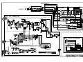
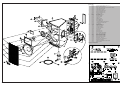
Index & Warnings
GENERALMUSIC S.p.a. Sales Division:47842 S.Giovanni in Marignano (RN) ITALY - Via delle Rose, 12 - tel. 0541/957404 - fax0541/957404 - http://www.generalmusic.com
SERVICE MANUAL
Notice
Service must be carried out by qualified personnel only. Any tampering carried out by unqualified personnel during the guarantee
period will forfeit the right to guarantee.
For a correct operation of the instrument, after having switched off, be careful to wait at least 3 seconds before switching on again.
To improve the device's specifications, the schematic diagrams may be subject to change without prior notice.
Schematic Diagrams
Schematic Notes
All components marked by this symbol have special safety characteristics, when replacing any of these components use only
manufacturer's specified parts.
The (µ) micro symbol of capacitance value is substituted by U. The (Ω) omega symbol of resistance value is substituted by E.
The electrolytic capacitors are 25Vdc rated voltage unless otherwise specified. All resistors are 1/4W unless otherwise specified.
All switches shown in the "OFF" position. All DC voltages measured to ground with a voltmeter 20KOhm/V.
CODE : 277322
Soldering point.
Supply voltage.
Male connector.
Logic supply ground.
Female connector.
Analog supply ground.
M/F faston connector.
Signal ground.
Test point.
Chassis ground.
ATTENTION
Observe precautions when handling
electrostatic sensitive devices
Flag joined with one or more flags with the same signal name inscribed.
1
r
r
2
+
-
-
+
3
r
r
4
5
r
Spare Parts
1
2
3
4
5
6
7
7
8
9
10
11
12
13
14
15
15
16
17
18
19
20
21
22
23
24
25
26
26
27
28
29
30
31
32
33
34
35
36
37
887074
768030
768126
768043
768042
768128
767987
768002
667613
667610
659027
717054
347287
347286
347187
237064
237065
229030
347283
227038
177476
177325
150591
141202
141184
140526
140212
130297
130283
120319
120125
120111
120108
120099
120098
110614
110297
110291
180637
177474
XLR MALE-FEMALE SIGNAL CABLE (mt. 1.5)
DISPLAY & SETTING BOARD
SIGNAL INPUTS CONTROLS & MIDI INTERFACE BOARD
POWER AMPLIFIER BOARD
POWER SUPPLY BOARD
CONVY PROCESSOR BOARD
MAINS FILTER BOARD (EU)
MAINS FILTER BOARD (US)
CONTROLS PANEL
METAL GRID
CYL. KNOB WHITE CAP
WOODEN CABINET
PLASTIC HANDLE
HANDLE SET
RUBBER HANDLE
TRANSFORMER (EU)
TRANSFORMER (US)
2" COMPRESSION DRIVER TWEETER
COMPRESSION DRIVER HORN
15" SPEAKER
AMPLIFIER HEAT SINK
STAND ADAPTOR
DISPLAY RED GLASS
XLR MALE SOCKET
XLR FEMALE SOCKET
GRAY BUTTON
DIN SOCKET
MAINS CORD (EU)
MAINS CORD (US)
WL 4x15 MAINS CORD SCREW
M5x35 MAINS CORD SCREW
M6x25 MAINS CORD SCREW
M5x30 MAINS CORD SCREW
M4x25 MAINS CORD SCREW
M4x20 MAINS CORD SCREW
MAINS INLET (EU)(US)
2 POLES 2 POS. SLIDE SWITCH
MAIN SWITCH (EU)(US)
ADHESIVE "GENERALMUSIC-LEM" BRAND
DRIVER HOLDER
Inputs Controls Panel
r
6
TOUR MASTER 15,2 ACTIVE - Technical Specification
SPEAKER SPECIFICATIONS
High
COMPONENTS
2" driver with controlled directivity horn
15" low frequency speaker
Low
HIGH section POWER HANDLING
W continuous
75
(EIA RS-426A)
W peak
240
LOW section POWER HANDLING
W continuous
800
(EIA RS-426A)
W peak
2400
ohm
8
High
IMPEDANCE (nominal)
Low
4
Cabinet: birch playwood
CONSTRUCTION
Finish: Black scratch-resistant paint
BIAS ADJUSTMENT
Instruments, materials and tools:
- Audio Generator
- Dual Trace Oscilloscope
- Digital Voltmeter (or Multimeter)
- 4Ω 500W and 8Ω 100W Resistors
- Temperature Meter
Setup:
-
Connect the Audio Generator to the input and set its output at 2KHz sinusoidal signal.
Insert the temperature sensor through the interstize between the heatsink and R93 (PTC).
Connect the 4Ω 500W resistor to the amplifier output instead of the woofer speaker and 8Ω 100W instead of tweeter speaker.
Connect the oscilloscope probes (setting 20V/div.,1ms/div.) on the loads.
Insert the voltmeter terminals on R107.
ADJUSTMENT PROCEDURE
Protection grille: metal grille
WEIGHT
DIMENSIONS
kg - lbs.
48,5 - 106,8
mm - in.
470x790x465 (LxAxP) - 185x311x183(WxHxD)
PROCESSOR SPECIFICATIONS
1)
2)
3)
4)
5)
6)
7)
Turn on the amplifier, pressing "UP" "DOWN" and "MIDI" simultaneously, check that the display shows "C".
Set the input signal to 0dB (0.775Vrms).
When the temperature has reaches about 45°C (109°F) set the signal input to minimum (0 or - ).
Adjust the trimmer R111 to read a voltage of 6mV ±0.1 on the multimeter.
Check that the voltage across the R108 resistor has the same value.
At the same temperature condition, adjust the VR1 trimmer to read 2.2mV ±0.1 at R24 resistor.
Check that the voltage on the R25 resitor has the same value.
Sensitivity
dB
0 (0.775Vrms)
Impedance
Kohm
30 (balanced) - 15 (unbalanced)
A/D converter
bit
18
D/A converter
bit
18
Veryfing:
Dynamic range
dB
105
Sampling rate
KHz
48
Frequency
Hz
1350
Slope
dB/oct.
24
1) Increase the input level to obtain an output voltage about of 0.5Vpp.
2) Check with the oscilloscope that the output signal is without a cross-talk distortion and eventually slightly
adjust the R111 or VR1 position until distortion disappears.
(Note: the voltage value across the R107 or R108 resistor must not exceed 10mV and the R24 or R25 resistor must
not exceed 4mV).
HIGH section POWER AMPLIFIER
W continuous
150
LOW section POWER AMPLIFIER
W continuous
650
AMPLIFIERS DISTORTION
THD +Noise
<0,02%
INPUT
CROSSOVER
VOLUME control
CONTROLS
LIMITER ADJUSTEMENT
1) Increase the input level to 10dB, adjust the trimmer VR1 until clipping distortion disappears.
2) Verify tha the led change colour from green to red.
3) Re-connect the speakers instead of the 4Ω and 8Ω resistors.
UP & DOWN selector buttons
MIDI button
Earth Lift
2-digit display
DISPLAY
SIGN/COMP LED
CONNECTORS
1 XLR-F +1 XLR-M (input + link)
MIDI in & MIDI THRU
POWER SUPPLY
230V ±15% 50/60Hz - 115V ±15% 50/60Hz
SYSTEM SPECIFICATIONS
Hz
FREQUENCY RESPONSE
SENSITIVITY
SPL 1W/1m dB
MAX SPL continuous
DISPERSION ANGLE
98
127
horizontal °
60 (±10)
vertical
40 (±7)
12
DIRECTIVITY Factor (Q)
DIRECTIVITY Index Di
50 ÷ 20000 (-10dB)
dB
11 (+2.8 , -4)
Note:the system specifications have been calculated using PRESET n.1 FLAT
7
r
SPARE PARTS LIST
ACCESSORIES
887074 XLR Female-Male Signal Cable (1.5mt)
277310 Owner’s Manual
ASSEMBLY
667613 Controls Panel
659027 Cyl. Knob White Cap
237064 Transformer (230V)
237065 Transformer (115V)
150591 Display Red Glass
110614 Mains Socket
110291 Power Switch
110037 T6.3A Fuse 6.3x32mm (US)
110035 T2.5A Fuse 6.3x32mm (US)
110034 T800mA Fuse 6.3x32mm (US)
110022 T8A Fuse 6.3x32mm (US)
110029 T4A Fuse 5x20mm (EU)
110023 T8A Fuse 5x20mm (EU)
110018 T6.3A Fuse 5x20mm (EU)
110015 T800mA Fuse 5x20mm (EU)
110014 T2.5A Fuse 5x20mm (EU)
667506 Left Side Bar
717054 Wooden Cabinet
667610 Metal Grid
347287 Plastic Handle
347286 Plastic Set
347283 2" Comprission Driver Horn
347187 Plastic Grip
229030 2" Compression Driver Tweeter
227038 15" Speaker
177474 Driver Holder
177325 Stand Adapter
130297 Mains Cord (EU Version)
130283 Mains Cord (US Version)
CONVY Processor Board
758128
230569
141059
141015
141013
141010
100943
100919
100737
100643
100642
100612
100061
100059
100058
080103
050494
050492
010722
010720
557026
105001
CONVY Processor Board (PCB#313020)
*
FL5R200PNT EMI Coil For Signal
*
Con V M 9 C Mini Mate Burndy
*
Con V F 14c P=1.27 Mmatch Amp
*
Con V F 10c P=1.27 Mmatch Amp
*
4 Contacts Vert Female Connector
*
MC33079 Quad Ln Op Amp
*
MC33078 Dual LN J-Fet Operational Amplifier
*
ADMOD79 2ch Ad Delta Modulator
*
AD1865N Dual 18bit Dac
*
TS93C46 1Kbit Eeprom Memory
*
74HC374 Octal D-Type Flip-Flop
*
TL072 Dual J-Fet Operational Amplifier
*
7805 +5V 1A Voltage Regulator
*
7905 -5V 1A Voltage Regulator
*
1N4148 100mA 75V Signal Diode
*
Resistor Array 10K X5 1/8w 5%
*
10Kx8 1/8w 5% Resistor Array
*
24.576MHz Quartz Resonator
*
12MHz Ceramic Resonator With Capacitors
*
AT89C55-12JC Programmed CPU
*
CONVY Dsp Convolver
768042
141060
141013
140081
140069
100060
100059
100049
080606
080168
030882
030881
030866
030858
030560
*
**
**
**
**
**
**
**
**
**
**
**
**
**
**
768126
757942
141202
141184
141064
Signal Input, Controls & MIDI Interface Board (PCB#313019)
*
Photores Coupler
*
Hor. Male XLR Socket (M21bc Nuova Asme)
*
Hor. Male XLR Socket (NC3FPRH Neutrik)
*
9 Contacts Hor. Male Connector
Power Supply Board
Power Supply Board (PCB#317191)
Con V M 12c Mini Mate Burndy
Con V F 10c P=1.27 Mmatch Amp
H 2c P=10 Terminal Block
H 3c P=10mm Terminal Block
7815 +15V 1A Voltage Regulator
7805 +5V 1A Voltage Regulator
7915 -15v 1a Voltage Regulator
GBU8D 8A Rectifier Diodes Bridge
W02M 1.5A Rectifier Diodes Bridge
10000uF 50V Snap-In Electrolytic Capacitor
10000uF 50V Snap-In Electrolytic Capacitor
4700uF 100V Snap-In Electrolytic Capacitor
4700uF 25V 20% Vert Electrolytic Capacitor
4700uF 80V 20% Snap-In Electrolytic Capacitor
Signal Input Controls & MIDI Interface Board
r
8
141010
140212
100602
100061
100035
090194
090183
080734
080245
080103
074570
070125
140526
*
*
*
*
*
*
*
*
*
*
*
*
*
4 Contacts Vert Female Connector
Horizontal Female 5 Poles Din Socket
74HC04 Hex Inverter
TL072 Dual J-Fet Operational Amplifier
6N138 Optocoupler
BC560 TO92 LN Pnp Transistor
BC550 To92 Ln Npn Transistor
Led 2.5x5mm Rect Diff Red-Grn LED
7V5 1W 5% Zener Diode
1N4148 100mA 75V Signal Diode
5K lin. 31 clicks Potentiometer
1K 20% Vertical Linear Trimmer
Gray Button
768030
141015
140526
080717
*
**
**
**
767987
768002
230565
140010
110113
110114
020493
010719
*
*
**
**
**
**
**
**
727524
768043
141059
141058
110316
110307
100084
100061
090920
090917
090916
090201
090200
090924
090923
090920
090919
090918
090917
090916
090863
090862
080282
080261
080245
080241
080171
080156
080103
070106
070082
080819
080607
080606
Power Amplifier Assenbly
*
Power Amplifier Board (PCB#319044)
** 9 Contacts Vert. Male Connector
** 6 Contacts Vert. Male Connector
**
Relay 24V / 1 Switch no 16A 250V
**
Relay 24V / 2 Switch 5A 250V
** TL074 Quad J-Fet Operational Amplifier
**
TL072 Dual J-Fet Operational Amplifier
** Mje803 TO126 Npn Darl Transistor
** MJE350 TO126 Pnp Transistor
** MJE340 TO126 Npn Transistor
**
2N5401 TO92 Pnp Transistor
** 2N5550 TO92 Npn Transistor
** MJL21194 NPN Transistor
**
MJL21193 PNP Transistor
** MJE802P PNP Transistor
** MJE15031 PNP Transistor
**
MJE15030 NPN Transistor
** MJE350 PNP Transistor
**
MJE340 NPN Transistor
**
TIP36C PNP Transistor
** TIP35C NPN Transistor
**
13V 1W 5% Zener Diode
**
10V1W 5% Zener Diode
** 7V5 1W 5% Zener Diode
** 5V6 1W 5% Zener Diode
**
FE6B 6A 100V Fast Recovery Diode
**
1N4002 1A 100V Rectifier Diode
**
1N4148 100mA 75V Signal Diode
**
470E 20% Horizontal Linear Trimmer
**
220E 20% Horizontal Linear Trimmer
*
PTC 70 Pth59f04bg222ts
*
KBPC25 25A 200V Bridge Rectifier Diode
*
GBU8D 8A Rectifier Diodes Bridge
Display & Setting Board
Display & Setting Board (PCB#319046)
Con V F 14c P=1.27 Mmatch Amp
Microswitch 100V 100ma 0.8mm
HDN1105 7 Segments Display
Mains Filter Board
Mains Filter Board (Pcb#315016) (EU)
Mains Filter Board (Pcb#315016) (US)
2.5mH 250V 3A AC Line Filter
3 Contacts P=10 Vert Terminal Block
Fuse Clip 5x20mm 6A max (EU)
Fuse Clip 6.3x32mm 10A Max (US)
100n 250Vac MKP EMI Capacitor “Siemens”
2n2 250Vac 7A 20% AC Line “Y” Filter “Murata”
Power Amplifier Assembly
Notes:
Each spare part is single quantity unless otherwise specified
Asterisk prefix explanation:
Omitted
= First level spare part.
One asterisk
= Second level, part of previous listed first level part.
Two asterisks
= Third level, part of previous listed second level part.
Three asterisk
=.......................
Any request for not above mentioned part must encompass specific description including:
1) Model name,
2) Section,
3) Module code,
4) Reference name,
5) Quantity number.