1
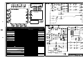
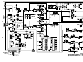
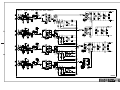
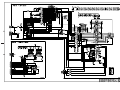
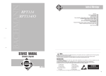
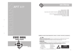
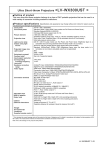
Index
4
5
6
7
8
9
10
3
11
12
Second Edition
Warnings
✔
✔
✔
SERVICE MANUAL
BLUES 8
Main Board (Master & Power Supply)
Main Board (1-4 Mono Channels)
Main Board (Stereo Channels)
BLUES 12
Main Board (Master & Power Supply)
Main Board (1-4 Mono Channels)
Main Board (5-8 Mono Channels)
Main Board (Stereo Channels)
BLUES 8 - 12
Wiring Connections, Functional Block Diagram, Level Diagram
DSP Board, Display Board
Spare Part List
Notice
Service must be carried out by qualified personnel only. Any tampering carried out by unqualified personnel during the guarantee period
will forfeit the right to guarantee.
For a correct operation of the instrument, after having switched off, be careful to wait at least 3 seconds before switching on again.
To improve the device's specifications, the schematic diagrams may be subject to change without prior notice.
All components marked by this symbol have special safety characteristics, when replacing any of these components use only
✔
✔
✔
✔
✔
✔
✔
✔
✔
manufacturer's specified parts.
The (µ) micro symbol of capacitance value is substituted by U.
The (Ω) omega symbol of resistance value is substituted by E.
The electrolytic capacitors are 25Vdc rated voltage unless otherwise specified.
All resistors are 1/8W unless otherwise specified.
All switches shown in the "OFF" position. All DC voltages measured to ground with a voltmeter 20KOhm/V.
Soldering point.
Supply voltage.
Logic supply ground.
Test point.
Analog supply ground.
Male connector.
Female connector.
M/F faston connector.
ATTENTION
Flag joined with one or more flags
with the same signal name inscribed.
Chassis ground.
Earth ground.
Observe precautions when handling electrostatic sensitive devices.
Address
CODE: 277316
✒
☎
GENERALMUSIC S.p.A. Sales Division: 47842 S.Giovanni in Marignano (RN) ITALY - Via delle Rose, 12
Phone +39(0)541/959511 - Fax +39(0)541/957404 - GENERALMUSIC on the NET: http://www.generalmusic.com
H
Opening Instructions
- To remove the front panel from the chassis unscrew the eleven screws that anchor the apparatus ( A).
- Remember to remove the earth screw ( B ) from the rear side too.
A
A
A
A
B
A
A
A
A
A
A
A
H - To remove the main board from the front panel unscrew the screws in sight (
- Moreover remove the sliders knobs (
), unscrew the joy-stick cap (
).
) and the jacks nut (
).
TECHNICAL SPECIFICATIONS
SECTION
MONO INPUT CHANNEL
MIC input
LINE input
Equalizer
STEREO INPUT CHANNEL
LINE input
PHONO input
Equalizer
MASTER SECTION
MASTER output level
MONITOR output level
AUX output level
TAPE IN input level
TAPE OUT output level
HEADPHONES output
GENERAL SPECIFICATIONS
TOTAL HARMONIC DISTORTION
CROSS-TALK
NOISE
WEIGHT
DIMENSIONS
POWER SUPPLY
Pow er supply
Weight
Dimensions
LEVELS & DATA
CONNECTORS
sensitivity
gain
impedence
sensitivity
gain
impedence
HI
LOW
from -45 to -15dB
30dB
1Kohms
from +10 to -20dB
30dB
10Kohms
±15 dB @ 10kHz
±15 dB @ 70Hz
Balanced XLR_F
sensitivity
impedence
sensitivity
impedence
HI
LOW
0dB
10Kohms
-45dB
47Kohms
±15 dB @ 10kHz
±15 dB @ 70Hz
2 Balanced JACKS
+4dB
+4dB
0dB
0dB
+4dB
Minimum impedance 30 ohms
2 x Balanced JACKS
2 x Balanced JACKS
Balanced JACK
2 x pin RCA
2 x pin RCA
Stereo JACK
STEREO separation
FADER
ON
(all fader closed)
(fader MIX nominal)
(fader MIX nominal +1ch.)
BLUES 8
BLUES 12
BLUES 8
BLUES 12
Balanced JACK
2 x pin RCA
<0,1% from 20Hz to 20KHz
>-80dB @ 1KHz, >-70dB @ 10KHz
>-90dB @ 1KHz, >-85dB @ 10KHz
>-100dB @ 1KHz, >-90dB @ 10KHz
-115 dB
-105 dB
-100 dB
3 kg
3,5 kg
324x310x58 mm (WxHxD)
340x310x58 mm (WxHxD)
see label on the apparatus
1kg
102x75x61,5mm (WxHxD)
! H
H "
# H
H $
% H
H &
' H
H H
SPARE PART LIST
RELEASE 2.0 updated July 23 1998
NOTE:
Starts from April 1998 the Blues mixers are manufactured in China, the spare parts are referred to these new and old versions.
You may recognize the version from the apparatus identifier plate:
951051, 951052, 951053 and 951054 are the old versions made in Italy
951112, 951113, 951114 and 951115 are the new verions made in China
All parts are replaceable between the two versions with the follow precautions:
1) The white connectors are different, so you could reuse the connectors of the older Board or order the appropriate connectors and cables
that you need.
2) The Jack and RCA sockets are different.
3) The Front Panels are different.
All the schematics are unchanged.
Legend
EU
US
Italy
China
Code
= Specify European Version (230Vac).
= Specify United States Version (115Vac).
= Manufactured in Italy, old version.
= Manufactured in China, new version.
Description
Accessories
951077
951078
277315
230V Ac/Ac Adapter PS30 (EU)
115V Ac/Ac Adapter PS30 (US)
Owner’s Manual
Assembly
667635
667634
PHC667005
667637
667636
PHC667006
347354
347343
347342
340754
340120
Chassis (Blues 8)
Front Panel (Blues 8) (Italy)
Front Panel (Blues 8) (China)
Chassis (Blues 12)
Front Panel (Blues 12) (Italy)
Front Panel (Blues 12) (China)
Gray/Yellow Slider Knob
Gray/White Slider Knob
Gray/Red Slider Knob
Rubber Foot
Plexiglass Display Screen
Dsp Board
768132
PHC768003
557028
141018
141011
140918
PHC145002
140872
PHC145004
105007
104019
104000
103025
103021
103016
103010
103003
081000
010735
DSP Board (PCB#319062) (Italy)
DSP Board (PCB#319062) (China)
*
Programmed Cpu
*
20 Contacts Vert Female Connector
*
6 Contacts Vert Female Connector
*
2 Contacts Hor Male Connector (Italy)
*
2 Contacts Hor Male Connector (China)
*
4 Contatcs Hor Male Connector (Italy)
*
4 Contatcs Hor Male Connector (China)
*
TMS57002 Dsp
*
ST24W02 Smd 2Kbit Serial Access EEprom
*
HM628128LFP7 SOP 1Mbit (128Kx8) Static Ram
*
74HC4040 12-Stage Binary Counter
*
TDA1309HN2 Bitstream Ad/Da Converter
*
74HC373DW SOIC Octal D-Type Latch
*
74HC04D SOIC Hex Inverter
*
74HC374DW Soic Octal D-Type Flip-Flop
*
PMLL4148 Smd 100mA 75V Signal Diode
*
8MHz Ceramic Resonator
Display Board
768131
PHC768002
110260
141013
140918
PHC145002
100613
080717
080705
Display Board (PCB#313018) (Italy)
Display Board (PCB#313018) (China)
*
9 Switches Compact Stick
*
10 Contacts Vert Female Connector
*
2 Contacts Hor Male Connector (Italy)
*
2 Contacts Hor Male Connector (China)
*
74HC4094 8 bit Sipo Latch Register
*
HDN1105 7 Segments Display
*
Led 3mm 60deg Diffused Red
Main Board
768130
768129
PHC768001
PHC768000
659129
347357
347356
347355
347353
H Main Board (PCB#313017) (Blues
Main Board (PCB#313016) (Blues
Main Board (PCB#313044) (Blues
Main Board (PCB#313043) (Blues
*
Gray Knob with Black Cover
*
Gray/Yellow Switch Button
*
Gray/White Switch Button
*
Gray/Red Switch Button
*
Gray/Yellow Knob
12) (Italy)
8) (Italy)
12) (China)
8) (China)
347348
347346
347345
347344
347334
347333
141188
141011
140918
PHC145002
140872
PHC145004
140397
140250
140236
PHC145001
140220
140212
110365
106004
106001
102007
100959
100923
100067
100066
100059
090183
080733
080731
080706
080705
080232
080168
080156
080103
075805
075802
075800
075699
075613
075590
075589
074761
074696
073596
073574
060378
042628
042475
042435
*
*
*
*
*
*
*
*
*
*
*
*
*
*
*
*
*
*
*
*
*
*
*
*
*
*
*
*
*
*
*
*
*
*
*
*
*
*
*
*
*
*
*
*
*
*
*
*
*
*
*
Gray/White Knob
Gray/Black Knob
Gray/Blu Knob
Gray/Red Knob
12 Leds Plastic Cover
12 Leds Plastic Support
XLR Female Connector
6 Contacts Vert Female Connector
2 Contacts Hor Male Connector (Italy)
2 Contacts Hor Male Connector (China)
4 Contatcs Hor Male Connector (Italy)
4 Contatcs Hor Male Connector (China)
2sw 2pos V Slider Switch
RCA Socket
Jack Vert Female Socket (Italy)
Jack Vert Female Socket (China)
Jack Slim Hor Female Socket
Horizontal Female 5 Poles Din Socket
2 ways - 4pos. Vertical Switch
LM393 Dual Voltage Comparator
MC33078P Smd Dual LN J-Fet Operational Amplifier
Hybrid 12 Led Level Meter
LM3171,2V-37V 0.1A Adjustable Regulator
NE5532A Dual LN Operational Amplifier
LM337 1.2-37V 1.5A Adjustable Regulator
LM317 1.2-37V 1.5A Adjustable Regulator
7805 +5V 1A Voltage Regulator
BC550 To92 Ln Npn Transistor
Led 2.5x5mm Rect Diffused Green
Led 2.5x5mm Rect Diffused Red
Led 3mm 60deg Diffused Green
Led 3mm 60deg Diffused Red
5V1 0.5W 5% Zener Diode
WL02 1.5A 200V Rectifier Diodes Bridge
1N4002 1A 100V Rectifier Diode
1N4148 100mA 75V Signal Diode
50K 14mm Vert Rotary MN Potentiometer w/Click (Aux/Mon)
2X50K 14mm Vert Rotary Log Potentiometer (Phones, Efx Return)
50K 14mm Vert Rotary LogC Potentiometer w/Click (Balance)
50K 9mm Vert Rotary Log Potentiometer (Efx)
2X10K 9mm Vert Rotary Log Potentiometer (Tape In)
10K 9mm Vert Rotary Log Potentiometer (Aux, Mon, Mono)
10K 9mm Vert Rotary Alog Potentiometer (Gain)
2X50K 14mm Vert Rotary Lin Potentiometer w/Click (High, Low S.)
50K 9mm Vert Lin Rotary Potentiometer w/Click (High, Low, Pan M.)
2x10K 60mm Log Slider Potentiometer (Stereo Fader)
10K 60mm Log Slider Potentiometer (Mono Fader)
100E 2W 10% Resistor
16K5 1/4W 1% Metalized Film Resistor
825E 1/4W 1% Metalized Film Resistor
432E 1/4W 1% Metalized Film Resistor
Wiring Connections
840768
841200
840803
840844
841199
841080
841201
841081
2 Wires 12.5cm Length Crimp Terminal Cable (Italy)
2 Wires 12.5cm Length Crimp Terminal Cable (China)
6 Wires 12.5cm Length Flat Cable
2 Wires 7.5cm Length Crimp Terminal Cable (Italy)
2 Wires 7.5cm Length Crimp Terminal Cable (China)
4 Wires 12.5cm Length Crimp Terminal Cable (Italy)
4 Wires 12.5cm Length Crimp Terminal Cable (China)
20/10+10 Wires 8cm Length Flat Cable
Notes:
Each spare part is single quantity unless otherwise specified
Asterisk prefix explanation:
Omitted
= First level spare part.
One asterisk = Second level, part of previous listed first level part.
Two asterisk = Third level, part of previous listed second level part.
Three asterisk =.......................
Any request for not above mentioned part must encompass specific description including:
1) Model name,
2) Section,
3) Module code,
4) Reference name,
5) Quantity number.