1
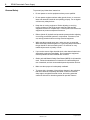
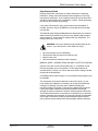
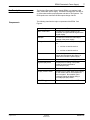
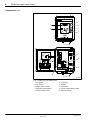
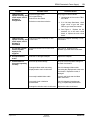
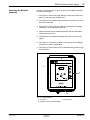
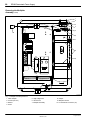
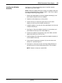
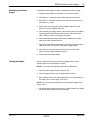
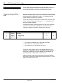
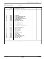
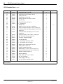
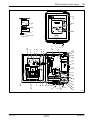
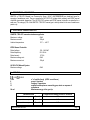
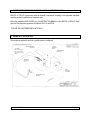
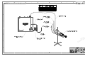
EPS6 Electrostatic
Power Supply
Customer Product Manual
Part 237381D
NORDSON CORPORATION D AMHERST, OHIO D USA
Nordson Corporation welcomes requests for information, comments and inquiries about its products. General information about Nordson can be
found on the Internet using the following address: http://www.nordson.com.
Address all correspondence to
Nordson Corporation
Attn: Customer Service
555 Jackson Street
Amherst, OH 44001
Notice
This is a Nordson Corporation publication which is protected by copyright. Original copyright date 1997. No part of
this document may be photocopied, reproduced, or translated to another language without the prior written consent
of Nordson Corporation. The information contained in this publication is subject to change without notice.
Trademarks
100 Plus, Blue Box, ChromaFlex, CleanSleeve, CleanSpray, Control Coat, Cross-Cut, Easy Coat, Econo-Coat,
Excel 2000, Flow Sentry, Isocoil, Isocore, Iso-Flo, Nordson, the Nordson logo, PRX, Pro-Flo, RBX, Ready-Coat,
Rhino, Select Coat, Select Cure, Shur-Lok, Smart Spray, System Sentry, Thread Coat, Tribomatic, and Versa-Spray
are registered trademarks of Nordson Corporation.
CPX, CanWorks, Excel 2000, PowderGrid, Pulse Spray, SCF, Versa-Coat, Versa Screen, Package of Values, and
Swirl Coat are trademarks of Nordson Corporation.
Manual 9-15
237381D
Issued 11/01
E 2001 Nordson Corporation
All rights reserved
Table of Contents
i
Table of Contents
1. Safety . . . . . . . . . . . . . . . . . . . . . . . . . . . . . . . . . . . . . . . . . . . . . . . . . . . . . 1
Qualified Personnel . . . . . . . . . . . . . . . . . . . . . . . . . . . . . . . . . . . . . . . 1
Intended Use . . . . . . . . . . . . . . . . . . . . . . . . . . . . . . . . . . . . . . . . . . . . 1
Regulations and Approvals . . . . . . . . . . . . . . . . . . . . . . . . . . . . . . . . . 1
Personal Safety . . . . . . . . . . . . . . . . . . . . . . . . . . . . . . . . . . . . . . . . . . 2
High-Pressure Fluids . . . . . . . . . . . . . . . . . . . . . . . . . . . . . . . . . . . 3
Fire Safety . . . . . . . . . . . . . . . . . . . . . . . . . . . . . . . . . . . . . . . . . . . . . . . 4
Halogenated Hydrocarbon Solvent Hazards . . . . . . . . . . . . . . . . 5
Action in the Event of a Malfunction . . . . . . . . . . . . . . . . . . . . . . . . . 5
Disposal . . . . . . . . . . . . . . . . . . . . . . . . . . . . . . . . . . . . . . . . . . . . . . . . . 5
Safety Labels . . . . . . . . . . . . . . . . . . . . . . . . . . . . . . . . . . . . . . . . . . . . 6
2. Description . . . . . . . . . . . . . . . . . . . . . . . . . . . . . . . . . . . . . . . . . . . . . . . . . 7
Components . . . . . . . . . . . . . . . . . . . . . . . . . . . . . . . . . . . . . . . . . . . . . 7
Features . . . . . . . . . . . . . . . . . . . . . . . . . . . . . . . . . . . . . . . . . . . . . . . . 9
Specifications . . . . . . . . . . . . . . . . . . . . . . . . . . . . . . . . . . . . . . . . . . . . 9
3. Installation . . . . . . . . . . . . . . . . . . . . . . . . . . . . . . . . . . . . . . . . . . . . . . . . 10
Installing the Power Supply . . . . . . . . . . . . . . . . . . . . . . . . . . . . . . . 10
Setting the Voltage . . . . . . . . . . . . . . . . . . . . . . . . . . . . . . . . . . . . . . . 11
Making Terminal Block Connections A–I and 1–4 . . . . . . . . . . . . . 12
Making Terminal Board Connections for PLC Interface . . . . . . . . 16
Installing the Electrostatic Cable . . . . . . . . . . . . . . . . . . . . . . . . . . . 18
Using the Microammeter . . . . . . . . . . . . . . . . . . . . . . . . . . . . . . . . . . 19
4. Operation . . . . . . . . . . . . . . . . . . . . . . . . . . . . . . . . . . . . . . . . . . . . . . . . . 19
Operating the EPS6 . . . . . . . . . . . . . . . . . . . . . . . . . . . . . . . . . . . . . . 19
5. Troubleshooting . . . . . . . . . . . . . . . . . . . . . . . . . . . . . . . . . . . . . . . . . . . 20
Troubleshooting Electrical Problems . . . . . . . . . . . . . . . . . . . . . . . . 20
Input Voltage Calibration . . . . . . . . . . . . . . . . . . . . . . . . . . . . . . . . . . 24
E 2001 Nordson Corporation
All rights reserved
237381D
Issued 11/01
Manual 9-15
ii
Table of Contents
6. Repair . . . . . . . . . . . . . . . . . . . . . . . . . . . . . . . . . . . . . . . . . . . . . . . . . . . . 25
Disassembling the Power Supply . . . . . . . . . . . . . . . . . . . . . . . . . . 25
Removing the Multiplier Assembly . . . . . . . . . . . . . . . . . . . . . . . . . 27
Installing the Multiplier Assembly . . . . . . . . . . . . . . . . . . . . . . . . . . . 29
Assembling the Power Supply . . . . . . . . . . . . . . . . . . . . . . . . . . . . . 31
Testing the Display . . . . . . . . . . . . . . . . . . . . . . . . . . . . . . . . . . . . . . . 31
7. Parts . . . . . . . . . . . . . . . . . . . . . . . . . . . . . . . . . . . . . . . . . . . . . . . . . . . . . 32
Using the Illustrated Parts List . . . . . . . . . . . . . . . . . . . . . . . . . . . . . 32
EPS6 Standard Parts . . . . . . . . . . . . . . . . . . . . . . . . . . . . . . . . . . . . 33
Cable Cleaning Kit . . . . . . . . . . . . . . . . . . . . . . . . . . . . . . . . . . . . . . . 36
Manual 9-15
237381D
Issued 11/01
E 2001 Nordson Corporation
All rights reserved
EPS6 Electrostatic Power Supply
1
EPS6 Electrostatic Power Supply
1. Safety
Read and follow these safety instructions. Task- and equipment-specific
warnings, cautions, and instructions are included in equipment
documentation where appropriate.
Make sure all equipment documentation, including these instructions, is
accessible to persons operating or servicing equipment.
Qualified Personnel
Equipment owners are responsible for making sure that Nordson
equipment is installed, operated, and serviced by qualified personnel.
Qualified personnel are those employees or contractors who are trained
to safely perform their assigned tasks. They are familiar with all relevant
safety rules and regulations and are physically capable of performing
their assigned tasks.
Intended Use
Use of Nordson equipment in ways other than those described in the
documentation supplied with the equipment may result in injury to
persons or damage to property.
Some examples of unintended use of equipment include
S
S
S
S
S
S
Regulations and Approvals
E 2001 Nordson Corporation
All rights reserved
using incompatible materials
making unauthorized modifications
removing or bypassing safety guards or interlocks
using incompatible or damaged parts
using unapproved auxiliary equipment
operating equipment in excess of maximum ratings
Make sure all equipment is rated and approved for the environment in
which it is used. Any approvals obtained for Nordson equipment will be
voided if instructions for installation, operation, and service are not
followed.
237381D
Issued 11/01
Manual 9-15
2
EPS6 Electrostatic Power Supply
Personal Safety
To prevent injury follow these instructions.
S Do not operate or service equipment unless you are qualified.
S Do not operate equipment unless safety guards, doors, or covers are
intact and automatic interlocks are operating properly. Do not bypass
or disarm any safety devices.
S Keep clear of moving equipment. Before adjusting or servicing
moving equipment, shut off the power supply and wait until the
equipment comes to a complete stop. Lock out power and secure the
equipment to prevent unexpected movement.
S Relieve (bleed off) hydraulic and pneumatic pressure before adjusting
or servicing pressurized systems or components. Disconnect, lock
out, and tag switches before servicing electrical equipment.
S While operating manual spray guns, make sure you are grounded.
Wear electrically conductive gloves or a grounding strap connected to
the gun handle or other true earth ground. Do not wear or carry
metallic objects such as jewelry or tools.
S If you receive even a slight electrical shock, shut down all electrical or
electrostatic equipment immediately. Do not restart the equipment
until the problem has been identified and corrected.
S Obtain and read Material Safety Data Sheets (MSDS) for all materials
used. Follow the manufacturer’s instructions for safe handling and
use of materials, and use recommended personal protection devices.
S Make sure the spray area is adequately ventilated.
S To prevent injury, be aware of less-obvious dangers in the workplace
that often cannot be completely eliminated, such as hot surfaces,
sharp edges, energized electrical circuits, and moving parts that
cannot be enclosed or otherwise guarded for practical reasons.
Manual 9-15
237381D
Issued 11/01
E 2001 Nordson Corporation
All rights reserved
EPS6 Electrostatic Power Supply
3
High-Pressure Fluids
High-pressure fluids, unless they are safely contained, are extremely
hazardous. Always relieve fluid pressure before adjusting or servicing
high pressure equipment. A jet of high-pressure fluid can cut like a knife
and cause serious bodily injury, amputation, or death. Fluids penetrating
the skin can also cause toxic poisoning.
If you suffer a fluid injection injury, seek medical care immediately. If
possible, provide a copy of the MSDS for the injected fluid to the health
care provider.
The National Spray Equipment Manufacturers Association has created a
wallet card that you should carry when you are operating high-pressure
spray equipment. These cards are supplied with your equipment. The
following is the text of this card:
WARNING: Any injury caused by high pressure liquid can be
serious. If you are injured or even suspect an injury:
S
S
S
S
Go to an emergency room immediately.
Tell the doctor that you suspect an injection injury.
Show him this card.
Tell him what kind of material you were spraying.
MEDICAL ALERT—AIRLESS SPRAY WOUNDS: NOTE TO PHYSICIAN
Injection in the skin is a serious traumatic injury. It is important to treat
the injury surgically as soon as possible. Do not delay treatment to
research toxicity. Toxicity is a concern with some exotic coatings injected
directly into the bloodstream.
Consultation with a plastic surgeon or a reconstructive hand surgeon may
be advisable.
The seriousness of the wound depends on where the injury is on the
body, whether the substance hit something on its way in and deflected
causing more damage, and many other variables including skin
microflora residing in the paint or gun which are blasted into the wound.
If the injected paint contains acrylic latex and titanium dioxide that
damage the tissue’s resistance to infection, bacterial growth will flourish.
The treatment that doctors recommend for an injection injury to the hand
includes immediate decompression of the closed vascular compartments
of the hand to release the underlying tissue distended by the injected
paint, judicious wound debridement, and immediate antibiotic treatment.
E 2001 Nordson Corporation
All rights reserved
237381D
Issued 11/01
Manual 9-15
4
EPS6 Electrostatic Power Supply
Fire Safety
To avoid a fire or explosion, follow these instructions.
S Ground all conductive equipment in the spray area. Use only
grounded air and fluid hoses. Check equipment and workpiece
grounding devices regularly. Resistance to ground must not exceed
one megohm.
S Shut down all equipment immediately if you notice static sparking or
arcing. Do not restart the equipment until the cause has been
identified and corrected.
S Do not smoke, weld, grind, or use open flames where flammable
materials are being used or stored.
S Do not heat materials to temperatures above those recommended by
the manufacturer. Make sure heat monitoring and limiting devices are
working properly.
S Provide adequate ventilation to prevent dangerous concentrations of
volatile particles or vapors. Refer to local codes or your material
MSDS for guidance.
S Do not disconnect live electrical circuits while working with flammable
materials. Shut off power at a disconnect switch first to prevent
sparking.
S Know where emergency stop buttons, shutoff valves, and fire
extinguishers are located. If a fire starts in a spray booth,
immediately shut off the spray system and exhaust fans.
S Shut off electrostatic power and ground the charging system before
adjusting, cleaning, or repairing electrostatic equipment.
S Clean, maintain, test, and repair equipment according to the
instructions in your equipment documentation.
S Use only replacement parts that are designed for use with original
equipment. Contact your Nordson representative for parts
information and advice.
Manual 9-15
237381D
Issued 11/01
E 2001 Nordson Corporation
All rights reserved
EPS6 Electrostatic Power Supply
5
Halogenated Hydrocarbon Solvent Hazards
Do not use halogenated hydrocarbon solvents in a pressurized system
that contains aluminum components. Under pressure, these solvents
can react with aluminum and explode, causing injury, death, or property
damage. Halogenated hydrocarbon solvents contain one or more of the
following elements:
Element
Fluorine
Chlorine
Bromine
Iodine
Symbol
F
Cl
Br
I
Prefix
“Fluoro-”
“Chloro-”
“Bromo-”
“Iodo-”
Check your material MSDS or contact your material supplier for more
information. If you must use halogenated hydrocarbon solvents, contact
your Nordson representative for information about compatible Nordson
components.
Action in the Event of a
Malfunction
If a system or any equipment in a system malfunctions, shut off the
system immediately and perform the following steps:
S Disconnect and lock out system electrical power. Close hydraulic and
pneumatic shutoff valves and relieve pressures.
S Identify the reason for the malfunction and correct it before restarting
the system.
Disposal
E 2001 Nordson Corporation
All rights reserved
Dispose of equipment and materials used in operation and servicing
according to local codes.
237381D
Issued 11/01
Manual 9-15
6
EPS6 Electrostatic Power Supply
Safety Labels
Table 1 contains the text of the safety labels on, or shipped with, the
Nordson Electrostatic Power Supply (EPS6). Figure 1 shows the location
of the labels that are described in the table below. Familiarize yourself
with the safety labels; they are provided to help you safely operate and
maintain your equipment.
Table 1 Safety Labels
Item
Part
Description
1.
------
WARNING: Electrical discharge can be dangerous. Turn off this unit.
Ground gun electrode and remove gun from spray area before performing
any servicing or cleaning.
2.
140 475
CAUTION: Input voltage on this unit can be adjusted for 115 Volts or 230
Volts. Failure to adjust this unit to proper input line voltage can cause
damage to this unit.
3.
184 258
WARNING: Do not locate this unit in an area classified as hazardous.
Install, operate, and service in accordance with all applicable safety codes
and Nordson instruction manual.
If you have questions concerning this electrostatic spray equipment, call
(440) 985-4000, and ask to speak with the Liquid Systems Group Technical
Service Department.
Nordson Corporation, Amherst, OH, 44001, U.S.A.
1
2
3
0915001A
Fig. 1 Location of Safety Labels
1. Front panel label
Manual 9-15
2. Inside cabinet label
237381D
Issued 11/01
3. Warning tag
E 2001 Nordson Corporation
All rights reserved
EPS6 Electrostatic Power Supply
2. Description
The Nordson Electrostatic Power Supply (EPS6) is a regulated, solid
state, electrostatic power supply. The EPS6 is designed for use with air
or airless electrostatic spray equipment and with Iso-Flo Systems. The
EPS6 produces a maximum variable output voltage of 60 kV.
Components
The following chart lists the major components of the EPS6. See
Figure 2.
Component
7
Function
Main circuit board
Creates and controls voltage for the
multiplier, and generates the signal for the
digital display.
Multiplier
Creates and controls the main output
voltage of the power supply.
Voltage select switch
Allows you to connect the power supply
to:
S 120 Vac or 240 Vac service
S 100 Vac or 200 Vac service
E 2001 Nordson Corporation
All rights reserved
Fuse
Limits the input current to the power
supply and disconnects the power if a
fault occurs inside the power supply.
Terminal blocks
Interconnect the power supply circuit.
Digital display board
Displays the kV setting of the power
supply or the current draw in
microamperes (μA).
Potentiometer knob
Adjusts the kV setting of the power supply.
Display selector switch
Enables you to select either the kV setting
or the current draw in microamperes at
the front panel. Also enables you to
remotely change the display using a
normally-open (NO) switch.
ON/OFF toggle switch
Turns the main power ON and OFF.
237381D
Issued 11/01
Manual 9-15
8
EPS6 Electrostatic Power Supply
Components (contd)
1
6
2
5
3
4
7
8
9
10
0915002A
Fig. 2 EPS6 (Front and Inside Views)
1.
2.
3.
4.
5.
Manual 9-15
kV indicator
mA indicator
Display selector switch
Adjustment potentiometer
Power ON/OFF switch
237381D
Issued 11/01
6.
7.
8.
9.
10.
kV ON light
Multiplier
Fuse holder
Internal voltage selector switch
Main circuit board
E 2001 Nordson Corporation
All rights reserved
EPS6 Electrostatic Power Supply
Features
9
The EPS6 offers the following design features:
S Variable output voltage at low amperage, which allows a safe but
highly efficient field of attraction between the coating material and the
workpiece.
S Digital display for monitoring kV output setting or output current.
S LEDs to help you troubleshoot the power supply.
S Programmable logic control (PLC) is also available for some
functions.
Specifications
Specification
Input voltage
Operating Requirements
120/240 Vac, "10%, 50/60 Hz
100/200 Vac, "10%, 50/60 Hz
E 2001 Nordson Corporation
All rights reserved
Input current protection
0.75-amp fuses
Variable output voltage
(open circuit)
30,000−60,000 Vdc, "3 kV
Output current
(short circuit)
150 μA, maximum
Display accuracy
"2 counts
Operating temperature
range
0 – +40°C (32 – +104°F)
Cabinet Dimensions
(H x W x D)
355.60 x 304.88 x 152.40 mm
(14.0 x 12.0 x 6.0 in.)
Door
Hinged at left-hand side
Unit weight
13.15 kg (29.0 lb)
237381D
Issued 11/01
Manual 9-15
10
EPS6 Electrostatic Power Supply
3. Installation
WARNING: Allow only qualified personnel to perform the
following tasks. Observe and follow the safety instructions in
this document and all other related documentation.
WARNING: This equipment can be dangerous unless it is used
in accordance with the rules laid down in this manual.
WARNING: Electrical discharge can be dangerous. Do not
install the power supply in an area classified as hazardous
(refer to NFPA-33 publication for specifications). Ground the
electrostatic power supply, all sprayed objects, fluid containers,
and other electrically conductive objects located within 6 m
(19.7 ft) of the spray area. Keep spray area, conveyors, and
hangers clean.
WARNING: Do not install the power supply on a reciprocator or
in an area where excessive vibration occurs. Do not place the
power unit where timers or signal devices are closely located.
These devices can affect the electrical operation of the
electrostatic power supply.
Installing the Power Supply
Mount the power supply in an accessible area for ease of operation and
maintenance. See Figure 3 for mounting dimensions.
Perform the following steps to mount the power supply:
1. To install the unit near the spray booth, allow at least a 1.5 m (5 ft)
radius outside the booth opening area.
2. Observe the mounting dimensions and clearance requirements for
the EPS6.
3. Remove the eight retaining screws (2) from the front panel door, and
then open the door.
4. See Figure 7 for wiring connections, and then secure the power
supply to the installation site using the four mounting screws (1).
5. Close the front panel door and secure it with the eight retaining
screws (2).
Manual 9-15
237381D
Issued 11/01
E 2001 Nordson Corporation
All rights reserved
11
EPS6 Electrostatic Power Supply
7.9 mm
(0.312 in.)
1
374.7 mm
(14.75 in.)
2
254 mm
(10 in.)
0915003A
Fig. 3 Mounting Dimensions and Clearance Requirements
1. Mounting screws (quantity of four)
Setting the Voltage
2. Retaining screws for front panel
(quantity of eight)
CAUTION: Verify that the main power source voltage
corresponds with the voltage rating indicated on the internal
voltage selector switch. If you connect 230-volt power with the
selector switch set at 115 volts, immediate fuse failure and
power supply damage can occur.
Nordson Corporation ships the power supply with the selector switch set
to the 230-volt position. If you require 115-volt power, move the selector
switch to the 115-volt position.
NOTE: If you connect 115-volt power with the selector switch set at 230
volts, reduced electrostatic efficiency and loss of wrap can occur.
E 2001 Nordson Corporation
All rights reserved
237381D
Issued 11/01
Manual 9-15
12
EPS6 Electrostatic Power Supply
Making Terminal Block
Connections A–I and 1–4
See Figure 4 and make the following terminal block connections on TB3
and TB4:
1. Remove any packing materials from inside the power supply.
2. Install liquid-tight, one-half inch conduit to the EPS6 and connect it
using only the Nordson-supplied conduit connector.
3. Install 18−22 gauge wire that meets local electrical codes through the
conduit and connect the main power supply leads to terminals A, B,
and C on TB4, as follows:
a. Connect ground wire (1) to TB4-A.
b. Connect power wire L1 (2) to TB4-B.
c. Connect power wire L2 (3) to TB4-C.
4. Connect a ground wire (12 gauge or larger) from the ground stud on
the power supply to a true earth ground.
5. Install the wires through the factory-supplied suppressor (4) for the
power wiring (L1, L2, and ground wires):
a. Open the suppressor (4).
b. Position wires L1 (2), L2 (3), and ground (1) through the
suppressor.
c. Tightly close the suppressor, without pinching the wires.
Manual 9-15
237381D
Issued 11/01
E 2001 Nordson Corporation
All rights reserved
13
EPS6 Electrostatic Power Supply
TB3
TB4
4
12 3
0913005B
Fig. 4 EPS6 Terminal Block (TB3, TB4) Connections
1. Ground wire
2. Power wire L1
3. Power wire L2
4. Suppressor
6. Connect terminals D, E (interlock terminals) as follows to interrupt
power to the EPS6 if the interlock switch opens:
a. Remove factory-installed jumper.
b. Connect customer-supplied interlock switch to terminals.
NOTE: Terminals J, K, and L have no connections (NC).
E 2001 Nordson Corporation
All rights reserved
237381D
Issued 11/01
Manual 9-15
14
EPS6 Electrostatic Power Supply
Making Terminal Block
Connections A I and 1-4 (contd)
7. Make one of the following required trigger connections:
a. See Figure 5 to use an air flow switch for contact closure when
you actuate the gun. Use the installation instructions that
accompany the air flow switch (1) to install the switch on the
EPS6.
Connect the air flow switch wires to TB3-1 (5), and TB3-2 (4).
Connect the air inlet line (3) to an air pressure source.
Connect the air outlet line (2) to your air spray gun.
b. See Figure 4. To use an electromechanical relay to provide
contact closure when you actuate the gun, connect the relay
contacts to TB3-1 and TB3-2.
c. To use a programmable logic controller (PLC) or another 24 Vdc
source to the EPS6, connect +V to TB3-10 and TB3-11.
NOTE: The EPS6 triggers when a voltage is applied.
Manual 9-15
237381D
Issued 11/01
E 2001 Nordson Corporation
All rights reserved
EPS6 Electrostatic Power Supply
5
4
15
1
2
3
0915005A
Fig. 5 Air Flow Switch Installed on EPS6
1. Air flow switch
2. Air outlet line (1/4-in. NPT)
3. Air inlet line (1/4-in. NPT)
4. TB3-2, Common
5. TB3-1, Trigger
8. To remotely select kV or microamps to show on the front panel
display, use TB3-4, kV/I Display:
a. Set the toggle switch on the front panel to kV.
b. Ground TB3-4 to remotely change the displayed reading from kV
to microamps.
E 2001 Nordson Corporation
All rights reserved
237381D
Issued 11/01
Manual 9-15
16
EPS6 Electrostatic Power Supply
Making Terminal Board
Connections for PLC
Interface
CAUTION: When connecting terminals 5 through 8, do not
exceed 24 Vdc maximum, otherwise, equipment damage can
occur.
NOTE: Terminals 5 through 11 are electrically isolated from the rest of
the circuit.
Terminal block connections 5 through 8 at TB3 allow you to use a
programmable logic controller (PLC) or other digital device to remotely
trigger and adjust the EPS6 using 12−24 Vdc logic.
See Figure 4 to make these optional terminal block connections at TB3.
These terminals provide the binary pattern that the power supply uses to
correctly set the voltage. The following digital pattern corresponds to the
kV settings shown in Table 2.
S
S
S
S
Terminal 5 = bit 8
Terminal 6 = bit 4
Terminal 7 = bit 2
Terminal 8 = bit 1
Table 2 EPS6 Voltage Settings
Bit
8
4
2
1
kV
0
0
0
0
15
0
0
0
1
18
0
0
1
0
21
0
0
1
1
24
0
1
0
0
27
0
1
0
1
30
0
1
1
0
33
0
1
1
1
36
1
0
0
0
39
1
0
0
1
42
1
0
1
0
45
1
0
1
1
48
1
1
0
0
51
1
1
0
1
54
1
1
1
0
57
1
1
1
1
60
NOTE: 1 = 24 Vdc
Manual 9-15
60 kV max
237381D
Issued 11/01
0 = 0 Vdc
E 2001 Nordson Corporation
All rights reserved
17
EPS6 Electrostatic Power Supply
Dip switches 2 and 3 on the main circuit board, SW1-5 (2) allow the PLC
to control the power supply. Refer to Table 3 and see Figure 6.
NOTE: The remaining dip switches on the main circuit board are for
factory settings only.
Table 3 Dip Switch Settings
PLC Control
Dip Switch
U4
CR13
R83
R39
R65
R61
R53
R64
R51
R75 R14
R43 R73
U15
Q1
R17
3
2
C21
R13
U2
C22
C3
R72
R70
1
U3
C1
R71
CR6
R1
U6
CR12
C19
C6
R7
C25
CR8
C4
R34
C7
Q5
U11
R79
R68
C13
V2
C5
C16
J1 24
R67
R12
R24
R9
CR10
R66
C15
C14
CR2
CR5
R10
R22
R32
R8
C17
R11
54321
U7
U5
R15
SW1−5
R78
Q3
Q7
V1
C9
J2
C24
R69
R74
CR9
CR1
C10
U9
R52 R80
Q6
U10
R77
R36
A1
1
R82
R58
R63
R46
R37
CR7
C20
R33
R38
CR16
R81
R29
R60
R76
R62
U12
6
J5
C11
4
5
U13
R59
R57
R55
U14
3
closed (down)
R54
R4
CR15
2
open (up)
CR3
R35
R49
R20
1
3
U8
J4
R18
open (up)
C12
CR14
C8
closed (down)
R56
C2
2
R23
R40 R19 C18
Front Panel Control
C23
1
0915006A
Fig. 6 Main Circuit Board
1. HV transformer connector (J2)
E 2001 Nordson Corporation
All rights reserved
2. Dip switch panel (SW1-5)
237381D
Issued 11/01
3. Q5 transistor
Manual 9-15
18
EPS6 Electrostatic Power Supply
Making Terminal Board
Connections for PLC
Interface (contd)
TB3-9, -10, and -11 provide the controls shown in Table 4.
Table 4 TB3-9, -10, -11 Connections
Terminal
Control
TB3-9, Strobe
Enables the EPS6 to read the bit pattern and
set the output voltage when the strobe voltage
goes to 24 volts.
TB3-10, Trigger
Enables the PLC to trigger the EPS6 using the
logic 1 (24 Vdc) signal. Use this terminal
instead of creating a short at TB3-1 and
TB3-2.
TB3-11, Common
Provides a ground terminal for the PLC unit.
This terminal connection is independent of
TB3-2 (ground for the EPS6) and is a required
connection for the digital interface to operate
correctly.
NOTE: TB3-12 is not connected (NC).
Installing the Electrostatic
Cable
Perform the following steps to install the electrostatic cable:
1. Use the cable cleaning kit to remove any contamination from both
ends of the electrostatic cable. Refer to Parts for kit ordering
information.
2. Cut the tip from the vial of high-voltage dielectric oil.
3. See Figure 9. Pour the contents of the vial of dielectric oil into the
high-voltage well (5) of the multiplier (7).
NOTE: Dielectric oil does not contain PCBs.
4. Slowly install the high-voltage cable into the multiplier well. Wipe
away any oil that overflows the well.
5. Secure the cable with the connecting nut and attach the cable strain
relief onto the side of the power supply cabinet.
6. Refer to the instructions in your gun manual and install the gun end of
the electrostatic cable to the spray gun. Tighten the connecting nut.
Manual 9-15
237381D
Issued 11/01
E 2001 Nordson Corporation
All rights reserved
EPS6 Electrostatic Power Supply
Using the Microammeter
19
The electrostatic power supply uses a microammeter for monitoring
output current. The microammeter is also useful for monitoring the
operating condition of the power supply. To test the microammeter, do
the following:
1. See Figure 2. After installing the spray device and cable to the power
supply, turn on the power supply using the power ON/OFF switch (5)
at the front panel.
2. Set the kV/μA switch on the front panel to microamps (μA).
3. Trigger the EPS6.
4. Observe the microammeter. If you are far from any grounded object,
the microammeter should read approximately 20–80 microamps.
5. Slowly move the gun electrode closer to ground; the microammeter
reading increases. The EPS6 will not automatically turn off when the
gun electrode approaches ground.
4. Operation
See Figure 2. The following instructions explain the daily operation for
your EPS6. Routine daily maintenance is not required.
Operating the EPS6
1. Apply power to the EPS6 using the power ON/OFF switch (5) on the
front panel. See Figure 2.
2. Set kV to the required setting using the adjustment potentiometer (4)
on the front panel. See Figure 2.
3. Hold the spray gun in your bare hand to ensure that you are
grounded.
4. Pressurize the fluid system.
5. Trigger the gun to begin spraying.
E 2001 Nordson Corporation
All rights reserved
237381D
Issued 11/01
Manual 9-15
20
EPS6 Electrostatic Power Supply
5. Troubleshooting
WARNING: Allow only qualified personnel to perform the
following tasks. Observe and follow the safety instructions in
this document and all other related documentation.
This section contains troubleshooting procedures. These procedures
cover only the most common problems that you may encounter. If you
cannot solve the problem with the information given here, contact your
local Nordson representative for help.
Troubleshooting Electrical
Problems
As you being to spray, notice the microammeter on the electrostatic
power supply. A normal operating reading is approximately 20–80
microamps. Use the operating current as a guide for troubleshooting.
For example, if the current reading starts to increase, the flow or
conductivity of the coating material might have increased, or moist or
dirty air has entered the system. A decrease in the current might indicate
that the power supply voltage has increased, or there is a poor path to
ground in the system, such a between product and its hanger or
conveyor.
WARNING: When checking the power supply with the spray
device and electrostatic cable removed, see Figure 4 and install
a jumper wire between TB3-1 and TB3-2 to energize the
high-voltage circuit. After completing the test, remove the
jumper.
NOTE: Keep the ball of the kV meter as far way as possible from any
grounded object.
Manual 9-15
237381D
Issued 11/01
E 2001 Nordson Corporation
All rights reserved
EPS6 Electrostatic Power Supply
21
The following table provides troubleshooting procedures for correcting
electrical problems. If multiple causes exist, the table lists those
problems in the order of importance.
Problem
1.
No output voltage at
nozzle; loss of wrap
with power ON, and
kV ON lamp
illuminated
E 2001 Nordson Corporation
All rights reserved
Possible Cause
Corrective Action
Poor ground to conveyor or coated part
Clean the conveyor, hooks, and part.
Poor ground to power supply
Provide true earth ground to the power
supply.
Spray device resistor failed
Remove the resistor from the spray
device and use a megohm meter to
measure resistance. Resistance should
read 75 megohms $10%; if it does not,
replace the resistor.
Needle resistor failed
Remove the needle from the spray
device. Use a megohm meter to
measure resistance. Resistance should
measure 12 megohms $10%; if it does
not, replace the needle.
Power supply malfunctioned
Use the kV meter to verify the
high-voltage output of power supply.
Output should measure 56–64 kV.
Spray device extension and nozzle
contaminated
Disassemble and clean the spray device
extension and nozzle.
Air supply contains water or
contaminates
Check the main air supply for
contaminates.
Voltage is arcing within extension
Replace the extension.
Electrostatic cable failed
Remove the cable from the spray
device. Use the kV meter to check the
kV at the gun end of the cable. The
cable should read 56–64 kV; if it does
not, replace the cable.
237381D
Issued 11/01
Manual 9-15
22
EPS6 Electrostatic Power Supply
Troubleshooting Electrical
Problems (contd)
Problem
2.
Front panel lamps do
not illuminate
Possible Cause
Output voltage missing or incorrect
Corrective Action
Verify the following:
1. The energized circuit breaker or
fuse is ahead of the power supply.
2. The fuses are installed and closed.
If a fuse is open, install a new
fuse.
3. The ON/OFF switch set to ON.
4. The interlock jumper is installed on
TB4-D and TB4-E.
3.
Power ON lamp
illuminated and the kV
lamp is not
Power supply not triggered
Use a length of wire to short TB3-1 and
TB3-2. If the kV lamp illuminates, verify
contact closure from the trigger circuit.
If the kV lamp does not illuminate,
replace the Q5 transistor on the main
circuit board.
4.
Power ON and kV
lamps illuminated, but
kV does not shut off
Defective transistor Q5
See Figure 6. Replace the Q5
transistor (3) on the main circuit board.
Air flow switch fixed in ON position
Verify that the air flow switch operates
correctly.
5.
Spray device does not
power off
Trigger switch on spray device requires
repair
Refer to the service manual for spray
device repair procedures.
6.
All front panel LEDs
and lamps
extinguished
Incorrect line voltage
Verify that the ON/OFF switch is set to
the ON position.
Verify that the fuse at the power
transformer is not open. If the fuse is
open, replace it.
Verify the input power at TB4-B and
TB4-C for correct voltage.
Calibrate the input voltage. Refer to
Input Voltage Calibration in this section.
If the existing input voltage settings do
not match the values given in Tables 5
and 6, replace the transformer.
Manual 9-15
237381D
Issued 11/01
E 2001 Nordson Corporation
All rights reserved
EPS6 Electrostatic Power Supply
Problem
7.
LEDs and lamps
operate correctly, with
no kV output, and kV
ON lamp is
extinguished
Possible Cause
Defective trigger switch
PLC signal missing
Defective air flow switch
Defective contact closure device
23
Corrective Action
Verify trigger circuit as follows:
1. Use a length of wire to short TB3-1
and TB3-2.
2. If kV ON lamp illuminates, check
trigger circuit of gun and cable.
Refer to gun instruction manual.
3. See Figure 6. Replace the Q5
transistor (3) on the main circuit
board, or replace the main circuit
board.
8.
LEDs and lamps
operate correctly, with
no kV output, and kV
ON lamp is
illuminated
Defective multiplier assembly or main
circuit board
Replace the multiplier assembly or main
circuit board.
9.
kV indicator remains
on even if power
supply is not
triggered
Defective transistor Q5 on main circuit
board
See Figure 6. Replace the Q5
transistor (3) on the main circuit board.
10. kV output weak or
erratic
Defective or damaged multiplier
Replace the multiplier.
11. Potentiometer on
front panel operating
correctly
Incorrect dip switch settings
Verify the correct dip switch settings on
the main circuit board.
Damaged ribbon cable connecting
display board to main circuit board.
Check for damaged ribbon cable
connecting the display board to the main
circuit board. Replace the cable, if
damaged.
Incorrectly installed ribbon cable
Correctly and firmly seat the ribbon
cable connectors.
Incorrectly wired or defective
potentiometer
Check for damaged potentiometer
wiring, or replace the potentiometer.
Damaged or defective main circuit board
Replace the main circuit board.
E 2001 Nordson Corporation
All rights reserved
237381D
Issued 11/01
Manual 9-15
24
EPS6 Electrostatic Power Supply
Input Voltage Calibration
WARNING: Disconnect equipment from line voltage before
servicing.
Use this procedure to test and calibrate the input voltage.
1. Disconnect and lock out the main power source.
2. Remove the main circuit board (see Figure 2, (10)) and turn on the
main electrostatic power supply.
3. Connect the electrostatic power supply to a power source following
these considerations:
S Connect 100/200 Vac units to a 100 Vac source
S Connect 120/240 Vac units to a 120 Vac source
4. Set the internal voltage selector switch (see Figure 2, (9)) to 120.
5. Measure the Vac on TB1-3, TB1-4, and TB1-5 according to the
values given in Table 5.
Table 5 Terminal Block 1 Voltage Values
Terminal
Voltage
3−4 (yellow to red)
18.2 Vac (± 1 V)
3−5 (yellow to red)
18.2 Vac (± 1 V)
4−5 (red to red)
36.4 Vac (± 2 V)
6. Turn off the electrostatic power supply.
7. Set the internal voltage select switch to 240 and turn on the
electrostatic power supply.
8. Measure the ac voltage on TB1-3, TB1-4, and TB1-5 according to the
values given in Table 6.
Table 6 Terminal Block 1 Voltage Values
Terminal
Voltage
3−4 (yellow to red)
9.1 Vac (± 1 V)
3−5 (yellow to red)
9.1 Vac (± 1 V)
4−5 (red to red)
18.2 Vac (± 1 V)
9. Turn off the electrostatic power supply.
10. Disconnect and lock out the main power source and reinstall the main
circuit board.
Manual 9-15
237381D
Issued 11/01
E 2001 Nordson Corporation
All rights reserved
EPS6 Electrostatic Power Supply
6. Repair
25
WARNING: Allow only qualified personnel to perform the
following tasks. Observe and follow the safety instructions in
this document and all other related documentation.
CAUTION: Follow disassembly and assembly steps in order.
Performing these steps out of sequence can cause damage to
the power supply, and can void your power supply warranty.
CAUTION: Disassembly of the high-voltage multiplier, main
circuit board, or power transformer will void your power supply
warranty.
During disassembly, repair, or assembly of your EPS6, do the following:
S See Figure 7. Use the wiring diagram to keep track of disconnected
wires.
S Handle circuit boards correctly and with care.
CAUTION: Do not use solvents of any type to clean internal
components of the EPS6, otherwise, equipment damage can
occur.
S Thoroughly clean and dry all components and cabinet before placing
the power supply into service again.
S When cleaning electrostatic components, such as cable ends or gun
extensions, use a Nordson Cable Cleaning Service Kit to clean and
dry the components. Refer to Parts for kit ordering information.
Disassembling the Power
Supply
Perform the following steps to disassemble the power supply:
1. Place the power supply ON/OFF switch to OFF.
2. Disconnect the main power supply and the electrostatic cable.
3. Cover the high-voltage outlet connector and cable end to prevent
contamination.
4. See Figure 5. Remove the air inlet (3) and outlet (2) lines from the air
flow switch (1), if used.
5. See Figure 8. Disconnect the ground cable at the ground stud (3).
6. Remove the power supply from the spray area and place on a clean
work surface for disassembly.
E 2001 Nordson Corporation
All rights reserved
237381D
Issued 11/01
Manual 9-15
26
EPS6 Electrostatic Power Supply
Disassembling the Power
Supply (contd)
0915007A
Fig. 7 EPS6 Wiring Diagram for 120/240-Volt Unit with Intrinsic Safety Barrier
Manual 9-15
237381D
Issued 11/01
E 2001 Nordson Corporation
All rights reserved
27
EPS6 Electrostatic Power Supply
Removing the Multiplier
Assembly
Perform the following steps, in order, to remove the multiplier assembly
from the power supply:
1. See Figure 8. Remove the eight retaining screws (2) from the front
panel (1), and then open the panel door.
2. See Figure 6. Disconnect the HV transformer connector J2 (1) from
the main circuit board.
3. See Figure 9. Remove the two clamps (8) that attach the multiplier
assembly (7) to the multiplier bracket (9).
4. Support the bottom of the multiplier assembly with your hand while
removing the locknut (2).
5. Carefully lower the multiplier assembly down and out of the power
supply.
6. See Figure 10. Remove the gasket (1) from the top of the multiplier
assembly (3). Set the gasket aside.
7. See Figure 9. Remove the screw (4) that retains the ground wire (6)
to the multiplier.
1
2
3
0915008A
Fig. 8 Front Panel Door
1. Front panel
2. Retaining screws (quantity of eight)
E 2001 Nordson Corporation
All rights reserved
237381D
Issued 11/01
3. Ground stud
Manual 9-15
28
EPS6 Electrostatic Power Supply
Removing the Multiplier
Assembly (contd)
1
2
3
4
5
10
6
7
8
9
0915009A
Fig. 9 Multiplier Assembly Removal
1.
2.
3.
4.
Cable adapter
Locknut (hex nut)
Gasket
Screw
Manual 9-15
5. High-voltage well
6. Ground wire
7. Multiplier assembly
237381D
Issued 11/01
8. Clamps
9. Multiplier bracket
10. HV transformer connector (J2)
E 2001 Nordson Corporation
All rights reserved
EPS6 Electrostatic Power Supply
Installing the Multiplier
Assembly
29
See Figure 10. Perform the following steps to install the multiplier
assembly into the power supply:
NOTE: When the multiplier fails by arc-tracking, the multiplier cable well
becomes contaminated with a conductive carbon. If this occurs, replace
the multiplier and the high-voltage cable.
1. Remove the cable adapter (2) from the multiplier assembly (3), and
then install the adapter on the new multiplier.
2. Tighten the cable adapter (2) to 4 N•m (3 ft-lb).
3. Use the screw (4) to connect the ground wire (5) to the cable
adapter (2) at the top of the multiplier assembly (3).
4. Install the gasket (1) over the end of the cable adapter (2) on the new
multiplier assembly (3).
5. See Figure 9. Place the multiplier assembly (7) in the cabinet, and
then install the locknut (2) on the cable adapter (1).
6. Position the multiplier firmly against the top of the cabinet, and then
tighten the locknut (2) to 4 N•m (3 ft lb).
7. Install and tighten the clamps (8) to attach the multiplier assembly (7)
to the multiplier bracket (9).
8. Connect the HV transformer connector J2 (10) to the main circuit
board at J2. (See also Figure 6.)
9. See Figure 9. Cut the tip from the vial of high-voltage dielectric oil,
and then pour the oil into the high-voltage well (5) of the multiplier.
NOTE: Dielectric oil does not contain PCBs.
E 2001 Nordson Corporation
All rights reserved
237381D
Issued 11/01
Manual 9-15
30
EPS6 Electrostatic Power Supply
Installing the Multiplier
Assembly (contd)
1
4
5
2
3
0915010A
Fig. 10 Multiplier Assembly Installation
1. Gasket
2. Cable adapter
3. Multiplier assembly
Manual 9-15
237381D
Issued 11/01
4. Screw
5. Ground wire
E 2001 Nordson Corporation
All rights reserved
EPS6 Electrostatic Power Supply
Assembling the Power
Supply
31
Perform the following steps, in order, to assemble the power supply:
1. Install the power supply on the booth or in its normal location.
2. See Figure 8. Connect the ground cable at the ground stud (3).
3. See Figure 5. Install the air inlet (3) and outlet (2) lines from the air
flow switch (1), if used.
4. Remove the cover and plug from the multiplier cable well. Add
dielectric oil to the multiplier cable well.
5. Verify that the high-voltage cable is clean and dry before you install it.
Use the Nordson Cable Cleaning Service Kit to clean and dry the
cable. Refer to Parts for kit ordering information.
6. Slowly install the high-voltage cable into the multiplier well. Wipe
away any oil that overflows the well.
7. Secure the electrostatic cable with the connecting nut and attach the
cable strain relief onto the side of the power supply cabinet.
8. See Figure 8. Close the front panel door and secure the front
panel (1) with the eight retaining screws (2).
9. Connect the main power supply.
Testing the Display
After you replace the main circuit board or display board, use the
following steps to test and adjust the display:
NOTE: Do not remove the display board from the EPS6 door.
1. Place the power supply ON/OFF switch to ON.
2. Turn the potentiometer on the front panel fully clockwise.
3. If the reading is 060, return the potentiometer to its original setting. If
the reading is not correct (060), go to step 4.
NOTE: Do not remove the display board from the power supply door to
perform step 4.
4. Locate R2 on the display board and use a small screwdriver to adjust
R2 until the display shows the correct reading.
E 2001 Nordson Corporation
All rights reserved
237381D
Issued 11/01
Manual 9-15
32
EPS6 Electrostatic Power Supply
7. Parts
To order parts, call the Nordson Customer Service Center or your local
Nordson representative. Use this five-column parts list, and the
accompanying illustration, to describe and locate parts correctly.
Using the Illustrated Parts
List
Numbers in the Item column correspond to numbers that identify parts in
illustrations following each parts list. The code NS (not shown) indicates
that a listed part is not illustrated. A dash (—) is used when the part
number applies to all parts in the illustration.
The six-digit number in the Part column is the Nordson Corporation part
number. A series of dashes in this column (- - - - - -) means the part
cannot be ordered separately.
The Description column gives the part name, as well as its dimensions
and other characteristics when appropriate. Indentions show the
relationships between assemblies, subassemblies, and parts.
Item
Part
Description
Quantity
—
000000
Assembly
1
1
000000
S Subassembly
2
2
000000
S S Part
1
Note
A
S If you order the assembly, items 1 and 2 will be included.
S If you order item 1, item 2 will be included.
S If you order item 2, you will receive item 2 only.
The number in the Quantity column is the quantity required per unit,
assembly, or subassembly. The code AR (As Required) is used if the
part number is a bulk item ordered in quantities or if the quantity per
assembly depends on the product version or model.
Letters in the Note column refer to notes at the end of each parts list.
Notes contain important information about usage and ordering. Special
attention should be given to notes.
Manual 9-15
237381D
Issued 11/01
E 2001 Nordson Corporation
All rights reserved
33
EPS6 Electrostatic Power Supply
EPS6 Standard Parts
Item
See Figure 11.
Part
Description
Quantity
Note
—
229934
Power Supply, EPS6, 120 or 240 Vac
1
—
229941
Power Supply, EPS6, 100 or 200 Vac
1
NS
184246
S Plate, suppressor, mounting
1
1
184273
S Panel, subassembly, 120/240 Vac
1
A
1
184253
S Panel, subassembly, 100/200 Vac
1
B
2
184264
S S Transformer, power
1
3
933161
S S Fuseholder
2
4
248704
S S Fuse, 0.75-amp, fast-acting, 250 V
2
5
933645
S S Block, terminal, 12-station
1
6
184265
S S Switch, voltage select, 115/230 Vac
1
7
184274
S Guide, card, 9.875 LG
1
8
184277
S Rod, threaded, 8.32 x 5.53 in.
2
9
184258
S Tag, warning
1
10
184259
S Switch, toggle, SPDT, VDE
1
NS
184261
S Boot, toggle switch
2
NS
184289
S Switch, toggle, DPST, VDE
1
11
184284
S Cable assembly, ribbon, 14-position, 10 in.
1
12
184252
S Board assembly, display, EPS
1
13
184287
S Wire group, display
1
NS
184285
S Spacer, switch, EPS
1
NS
184286
S Ring, locking switch
2
14
240674
S Tag, ground
2
15
240976
S Clamp, ground with wire
1
16
242867
S Tag, warning
1
17
246164
S Bracket, multiplier
1
1/
NS
248694
S Knob, collet, 28 mm,
NS
248695
S Cap, flat, 28 mm, with line
1
NS
248741
S Seal, shaft, rotary
1
185068
S Suppressor, ferrite, 13.4 mm dia
1
18
NOTE
4
in. shaft
A:
This subassembly is for use with EPS6, part 229934, only.
B:
This subassembly is for use with EPS6, part 229941, only.
1
NS: Not Shown
Continued on next page
E 2001 Nordson Corporation
All rights reserved
237381D
Issued 11/01
Manual 9-15
34
EPS6 Electrostatic Power Supply
EPS6 Standard Parts
Item
(contd)
Part
Description
Quantity
19
185067
S Suppressor, ferrite, 7 mm dia
4
20
185070
S Suppressor, ferrite, 24-position, R-Cab
1
21
970970
S Clamp, hose, #52
2
22
937189
S Potentiometer, 10,000 ohm
1
23
296038
S Spacer, 0.250 OD x 0.140 ID x 0.500 in.
4
24
140475
S Tag, warning
1
25
229937
S Board, assembly, main EPS 6
1
26
184970
S S Transistor, Q5
1
27
------
S Multiplier, HV
1
28
211274
S Gasket, 1.51 ID x 1.75 OD in., 70/90 duro
1
29
981149
S Screw, round head, #10-32 x 0.375 in., slotted, zinc
4
30
275989
S Screw, pan head, self-sealing, capt, #6-32 x 0.406 in.,
slotted, zinc
8
31
982623
S Screw, pan head, self-sealing, #10-24 x 0.375 in.,
slotted, zinc
2
32
981020
S Screw, pan head, #6-32 x 0.250 in., slotted, zinc
1
33
984121
S Nut, hex, mach, #10-24, slotted, zinc
2
34
805074
S Connector, straight, liquid-tight
1
NS
229933
S Kit, ship with, EPS
1
NS
229903
S S Tag, warning, hazardous, inserts
1
NS
229904
S S Tag, warning, dual-volt, inserts
1
35
983524
S Washer, lock, E, external, #6, steel, zinc
1
36
970972
S Clamp, cable, 0.562 in. dia
1
37
229905
S Adapter, multiplier/cable, EPS
1
38
983003
S Washer, flat, E, 0.156 x 0.312 x 0.032 in., zinc
4
39
982959
S Screw, flat head, #2-56 x 0.19 in., stainless steel
2
40
982966
S Retainer, captive screw, #6-32
8
41
242837
S Mount, cable strap
2
42
939004
S Strap, cable, 0.06–1.75 in., natural
2
43
180119
S Nut, lock, receptacle
1
44
184282
S Seal, oil-tight, 1.69 in. dia
1
NS
247512
S Oil, high-voltage insulating, pipette
1
NOTE
Note
C
C: This subassembly is available in kit, part 106381.
NS: Not Shown
Manual 9-15
237381D
Issued 11/01
E 2001 Nordson Corporation
All rights reserved
EPS6 Electrostatic Power Supply
35
30
40
10
25
26
22
7
8
View A−A
23
38
12
39 20
19
41
42
19 11
29
43
28
37
A
32
A
27
16
31
33
17
21
3
4
6
13
18
41
42
9
36 35
2
19 44 34
24
15
14
5
1
0915011A
Fig. 11 EPS6 Standard Parts
E 2001 Nordson Corporation
All rights reserved
237381D
Issued 11/01
Manual 9-15
36
EPS6 Electrostatic Power Supply
Cable Cleaning Kit
Part
106455
Manual 9-15
Use the following chart to order an electrostatic cable cleaning kit to use
with your electrostatic power supply.
Description
Service kit, cable cleaning
Quantity
1
237381D
Issued 11/01
E 2001 Nordson Corporation
All rights reserved
1. DESCRIPTION of EQUIPMENT
KINETIX or TRILOGY Manual Low Pressure Air Spray / KVLP (WATERBORNE) are hand-held guns for
spraying of waterborne paint. They are supplied by HD ISO-FLO (voltage block system) and EPS6 manual
controller (associated apparatus). The HD ISO-FLO system and EPS6 manual controller are installed in a
safe area. The category 2 G of the KINETIX / TRILOGY manual gun is strictly related to the use of waterborne
paints only.
2. ELECTRICAL CHARACTERISTICS
KINETIX / TRILOGY manual waterborne applicator
Maximum voltage:
60kV
Maximum current.
150µA
Ambient temperature:
0°C ÷ +40°C
EPS6 Manual Controller
Rated voltage:
Rated frequency:
Rated current.
Maximum voltage out:
Maximum current out:
120 – 240VAC
50 / 60 Hz
0.75 A
60kV
150µA
HD ISO-FLO Manual System
Maximum voltage:
60kV
3. MARKING
1180
1180
II
2
G
II 2 G
n° of notified body (ATEX surveillance)
group II (surface)
category 2 apparatus
explosive atmospheres caused by gas, mists or vapours of
waterborne
Maximum energy at the gun tip.
94 mJ
Hazardous area
Categories according to 94/9/CE Directive
Gas, mists or vapours
Zone 0
1G
Gas, mists or vapours
Zone 1
2G
Gas, mists or vapours
Zone 2
3G
Safety Note KINETIX/ATEX
Page 1
DOC13013B03
4. SAFETY INSTRUCTIONS FOR THE INSTALLATION IN HAZARDOUS AREA
KINETIX or TRILOGY liquid pistols shall be installed & maintained according to the applicable standards
regarding electrical installations in hazardous area.
Before the installation READ CAREFULLY the INSTRUCTION MANUAL of the KINETIX or TRILOGY liquid
pistol and the associated apparatus HD Manual ISO-FLO and EPS6.
FOR USE WITH WATERBORNE PAINTS ONLY!
5. EXAMPLE OF APPLICATION
This shows the applicators and how a typical system is configured.
ISO-FLO HD MANUAL
P/N 225579
AIR LINE
P/N 900511
3/8 O.D.
AIR HOSE
P/N 1074130 (30 FT)
P/N 1074131 (50 FT)
P/N 1074132 (100 FT)
3/8 I.D.
CABLE, 2 METER
P/N 297979
FLUID LINE
P/N 336720
¼ I.D.
EPS-6
P/N 229934
P/N 229941
MANUAL GUN, 60Kv
P/N 336671
Safety Note KINETIX/ATEX
Page. 2
DOC13013B03
Safety Note KINETIX/ATEX
Page. 3
DOC13013B03
6. DECLARATION OF CONFORMITY
Nordson Corporation
Headquarters in Westlake Ohio, USA
declare under our sole responsibility that the products
KINETIX or TRILOGY Liquid Applicators including Air Spray / KVLP Models used with HD Manual
ISO-FLO and EPS6. FOR USE WITH WATERBORNE PAINTS ONLY.
to which this declaration relates complies with the following Directives:
- Machinery Directive 89/37/EEC
- EMC Directive 2004/108/EC
- ATEX Directive 94/9/EC
The conformity are under observance of the following standards or standards documents:
EN12100
EN50059
IEC60417
EN61000-6-2
EN61000-6-3
EN55011
FM7260
Type of protection:
- II 2 G, max energy 94 mJ, Ambient temperature: 0°C to +40°C
EC type-examination certificate no:
- CESI 01 ATEX 030
- Milan Italy
N° of notified body (ATEX surveillance)
- 1180 (Baseefa) Buxton, Derbyshire, UK
ISO9000 certificate
DNV
Mike Hansinger
Manager Engineering Development
Safety Note KINETIX/ATEX
Date: 23 June 2009
Page. 4
DOC13013B03
DECLARATION of CONFORMITY
Product: Trilogy
Models: Trilogy Automatic Waterborne, HD Automatic ISO−FLO, EPS6
Description: Trilogy Automatic liquid waterborne applicator used with the HD automatic ISO−FLO voltage
block system and EPS6 Power Supply.
Applicable Directives:
Machinery Directive 2006/142/EC
EMC Directive 2004/108/EEC
ATEX Directive 94/9/EC
Standards Used for Compliance:
EN12100 (2003)
EN50348 (2002)
EN60204 (2006)
EN50059 (1990)
FM7260 (1996)
EN61000-6-3 (2007)
EN61000-6-2 (2005)
EN55011 (2009)
Type of protection:
Ex II 2 G, 93.24 mJ, Ambient temperature: 0 _C to +40 _C
Principles:
This product has been manufactured according to good engineering practice.
The product specified conforms to the directive and standards described above.
Certificates:
INERIS 05ATEX0068X, Verneuil en Halatte, FRANCE
ATEX Surveillance:
1180 (Baseefa) Buxton, Derbyshire, UK
Date: 31 August 2010
Mike Hansinger
Manager Engineering Development
Nordson Authorized Representative in the EU
Contact:
Operations Manager
Industrial Coating Systems
Nordson Deutschland GmbH
Heinrich−Hertz−StraBe 42−44
D−40699 Erkrath
Nordson Corporation S Westlake, Ohio
DOC13014A04