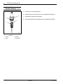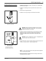
1
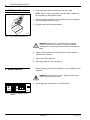
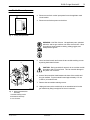
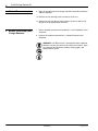
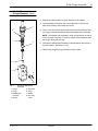
Instruction Sheet P/N 108 877A E-200 O-rings Service Kit 1. Introduction These instructions describe how to replace the o-rings in the E-200 gun module. It is necessary to remove and disassemble the module when replacing these o-rings. The instructions include the following: S S S S S S 2. Safety 3. Unit Preparation Safety Unit Preparation Module Removal Module Disassembly and O-rings Removal O-rings Replacement and Module Assembly Module Replacement WARNING: Allow only qualified personnel to perform the following tasks. Observe and follow the safety instructions in this document and all other related documentation. Perform the following steps to relieve hydraulic pressure before disassembling and replacing any gun component. WARNING: Risk of burns. Failure to relieve system pressure can result in hot material spraying from a connecting point, possibly causing serious burns. 1. Heat the system to operating temperature. 2. Turn the applicator pumps off. E 1995 Nordson Corporation All rights reserved 42--E200--IS--04 (formerly 46-253) Issued 8/95 P/N 108 877A 2 E-200 O-rings Service Kit 3. Unit Preparation (contd.) 3. Place a drain pan under the applicator’s filter drain valve. NOTE: Figure 1 shows a typical drain pan placement. Details may vary depending on the applicator model. 4. Follow instructions provided in your applicator’s technical manual for relieving system hydraulic pressure. 5. Properly dispose of the drained adhesive. 4110089 Fig. 1 Typical Drain Pan Placement WARNING: Risk of burns. Shield the area and operator. Failure to perform the next step can result in hot material spraying from a connecting point downstream of the applicator pump. 6. Trigger the gun module(s) from the gun driver to relieve pressure downstream of the pump. 7. Turn off the electric gun driver. 8. Wipe off any adhesive on the gun fittings. 1. Relieve hydraulic pressure as described in 3. Unit Preparation in this document. 4. Module Removal WARNING: Risk of electrical shock. Failure to observe may result in personal injury or death. 2. Set the applicator circuit breaker to the OFF position. 4103892 Fig. 2 Turning Off Applicator Circuit Breaker P/N 108 877A 42--E200--IS--04 (formerly 46-253) Issued 8/95 E 1995 Nordson Corporation All rights reserved E-200 O-rings Service Kit 3 4. Module Removal (contd.) 3. Disconnect and lock out the input power line to the applicator main circuit breaker. 4. Disconnect and lockout power to the driver. 4110132 Fig. 3 Locking Out Input Power WARNING: Hot! Risk of burns. Hot applicator parts, splashed adhesive, and hot gun surfaces can cause severe burns. Wear long-sleeved, heat-protective clothing, safety goggles, and heat-protective gloves. 5. Use a hex head wrench and loosen the two module retaining screws by turning them three full turns. 2 CAUTION: During module/coil removal, do not rock the module from side to side or front to back. This can result in damage to the plastic coil connector. 1 6. Insert a flat screwdriver blade between the base of the module and the gun manifold. Pry the module forward approximately 1.57 mm (0.062 in.) to break the seal. 7. Remove the two module retaining screws. 3 4204142 8. Unplug and remove the module/coil as an assembled unit from the gun manifold by lifting it straight off of the coil connector. Fig. 4 Removing Module/Coil Assembly 1. Module retaining screws 2. Module/coil assembly 3. Coil connector E 1995 Nordson Corporation All rights reserved 42--E200--IS--04 (formerly 46-253) Issued 8/95 P/N 108 877A 4 E-200 O-rings Service Kit 4. Module Removal (contd.) 9. Wipe off any adhesive left on the gun manifold, especially around the adhesive passage. 10. Remove the coil retaining screw from the top of the coil. 11. Remove the coil from the top of the module. Be sure to pull the coil straight off of the adapter/pole assembly. 5. Module Disassembly and O-rings Removal 1. Relieve hydraulic pressure as described in 3. Unit Preparation in this document. 2. Remove the module as described in 4. Module Removal in this document. WARNING: Hot! Risk of burns. Hot applicator parts, splashed adhesive, and hot gun surfaces can cause severe burns. Wear long-sleeved, heat-protective clothing, safety goggles, and heat-protective gloves. P/N 108 877A 42--E200--IS--04 (formerly 46-253) Issued 8/95 E 1995 Nordson Corporation All rights reserved E-200 O-rings Service Kit 5 5. Module Disassembly and O-rings Removal (contd.) 3. Remove and discard the o-ring from the back of the module. 3 4. Use a flat-blade screwdriver and remove the seal screw from the back of the module. Discard the seal screw. 5. Use a 2 mm hex wrench and turn the hex head screw clockwise until it no longer contacts the tapered edge of the adapter/pole assembly. 2 NOTE: The adapter pole assembly is under spring tension as well as friction from the o-ring seal. Thus there will be some resistance when removing it during the next step. 1 4 6. Unscrew the adapter/pole assembly counterclockwise and remove it from the module. Discard the o-ring. 7. Remove the plunger/spring assembly from the module. 8 7 5 6 4204144 Fig. 5 Removing Adapter/Pole Assembly 1. Spring 2. O-ring 3. Adapter/pole assembly 4. Plunger E 1995 Nordson Corporation All rights reserved 5. 6. 7. 8. Seal screw O-ring Module Hex head screw 42--E200--IS--04 (formerly 46-253) Issued 8/95 P/N 108 877A E-200 O-rings Service Kit 6 5. Module Disassembly and O-rings Removal (contd.) 8. Remove the four screws that hold the seat assembly to the module. 1 9. Remove the seat, gauge plate, seat guide, and o-ring. Discard the o-ring. 2 6 5 3 4 4204145 Fig. 6 1. Module 2. O-ring 3. Seat P/N 108 877A Removing Seat Assembly 4. Screws 5. Gauge plate 6. Seat guide 42--E200--IS--04 (formerly 46-253) Issued 8/95 E 1995 Nordson Corporation All rights reserved E-200 O-rings Service Kit 7 6. O-rings Replacement and Module Assembly 1. Coat the new o-ring with lubricant. 6 2. Place the seat guide and new o-ring into the seat. Attach this assembly to the module. NOTE: Do not install the gauge plate between the seat assembly and module at this time. This will be done at step 14. 5 3. Install and tighten the four screws through the seat assembly into the module. 4. Install the hex head screw into the top of the module. Do not tighten it at this time. 4 1 2 3 4204146 Fig. 7 Replacing Seat Assembly 1. O-ring 2. Seat 3. Screws E 1995 Nordson Corporation All rights reserved 4. Seat Guide 5. Module 6. Hex head screw 42--E200--IS--04 (formerly 46-253) Issued 8/95 P/N 108 877A E-200 O-rings Service Kit 8 6. O-rings Replacement and Module Assembly (contd.) 5. Coat the new o-ring with lubricant. 6. Install the new o-ring into the groove of the adapter/pole assembly. 3 2 7. Assemble the spring onto the plunger. 8. Insert the plunger/spring assembly into the adapter/pole assembly. 4 1 4204147 Fig. 8 1. O-ring 2. Seat P/N 108 877A Replacing Plunger/Spring Assembly 3. Screws 4. Seat Guide 42--E200--IS--04 (formerly 46-253) Issued 8/95 E 1995 Nordson Corporation All rights reserved E-200 O-rings Service Kit 9 6. O-rings Replacement and Module Assembly (contd.) CAUTION: Perform the following step while the module is inverted. Otherwise, binding and improper stroke setting may occur. 1 9. Install the adapter/pole assembly into the module. 2 10. Press the adapter/pole assembly down over the spring so that the screw threads meet. Screw the assembly into the module until it is fully seated. 3 11. Coat the o-ring in the new seal screw with lubricant and install the seal screw into the back of the module. 4 12. Turn the hex head screw counterclockwise until it just contacts the tapered edge of the adapter/pole assembly. Then tighten the screw against the adapter/pole assembly by turning it counterclockwise. Apply torque of 0.56 to 0.79 Nm (5 to 7 in-lb). 5 4204148 Fig. 9 Replacing Adapter/Pole Assembly 1. 2. 3. 4. 5. Module Seal screw Hex head screw Plunger/spring assembly Adapter/pole assembly E 1995 Nordson Corporation All rights reserved 42--E200--IS--04 (formerly 46-253) Issued 8/95 P/N 108 877A E-200 O-rings Service Kit 10 6. O-rings Replacement and Module Assembly (contd.) CAUTION: Perform the following step while the module is inverted to prevent the seat guide from falling out of place and causing improper gun operation. 3 2 4 13. Remove the four screws holding the seat assembly to the module. Remove the seat. 14. Install the gauge plate between the seat and the module. NOTE: The seat is under spring pressure during the next step. Alternately tighten each screw so that you apply pressure evenly during assembly. After positioning the seat fully against the module body, tighten the four screws securely. 1 15. Use the four screws and attach the seat to the module. Tighten the screws. 4204149 Fig. 10 Replacing Gauge Plate 1. 2. 3. 4. Module Seat Screws Gauge plate P/N 108 877A 42--E200--IS--04 (formerly 46-253) Issued 8/95 E 1995 Nordson Corporation All rights reserved E-200 O-rings Service Kit 11 1. Install the coil on top of the module. Be sure the coil is aligned with the back of the module. 7. Module Replacement 2. Install the coil retaining screw on top of the coil to secure it to the module. 3. Coat the new o-ring with lubricant. 4. Install the new o-ring in the grove in the back of the module. 4204143 Fig. 11 Installing O-ring in Back of Module/Coil Assembly CAUTION: During module/coil installation, do not rock the module from side to side or front to back. This can result in damage to the plastic coil connector. 5. Install the module/coil assembly onto the gun manifold by carefully plugging it into the coil connector. Make sure the module/coil assembly is straight and the module base is flush with the gun manifold. 1 CAUTION: Do not overtighten the screws. Overtightening can cause the head of the screw to break off. 2 6. Apply PTFE paste to the two module retaining screws that secure the module to the gun manifold. Install and tighten them. 4204140 Fig. 12 Aligning Module/Coil Assembly with Gun Manifold 1. Module/coil assembly 2. Module retaining screws NOTE: For best results, tighten the screws again after the applicator reaches operating temperature. 7. Restore the system to normal operation according to instructions in the applicator service manual. E 1995 Nordson Corporation All rights reserved 42--E200--IS--04 (formerly 46-253) Issued 8/95 P/N 108 877A 12 E-200 O-rings Service Kit Original copyright date 1995. Nordson and the Nordson logo are registered trademarks of Nordson Corporation. P/N 108 877A 42--E200--IS--04 (formerly 46-253) Issued 8/95 E 1995 Nordson Corporation All rights reserved