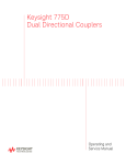
1
®
E stablished 1981
Advanced Test Equipment Rentals
www.atecorp.com 800-404-ATEC (2832)
Agilent 87512A/B TRANSMISSION/REFLECTION TEST KIT
OPERATION AND SERVICE MANUAL
SERIAL NUMBERS
This manual applies directly to instruments with serial number prex 3244J.
For additional important information about serial numbers, read
\INSTRUMENT COVERED BY MANUAL" in Chapter 1.
Agilent Part No. 87512-90020
Printed in JAPAN
February 2001
Notice
The information contained in this document is subject to change without notice.
This document contains proprietary information which is protected by copyright. All rights
are reserved. No part of this document may be photocopied, reproduced, or translated to
another language without the prior written consent of the Agilent Technologies.
Agilent Technologies Japan, Ltd.
Component Test PGU-Kobe
1-3-2, Murotani, Nishi-ku, Kobe-shi,
Hyogo, 651-2241 Japan
c Copyright 1990, 1992, 2000, 2001 Agilent Technologies Japan, Ltd.
Manual Printing History
The manual printing date and part number indicate its current edition. The printing
date changes when a new edition is printed. (Minor corrections and updates which are
incorporated at reprint do not cause the date to change.) The manual part number changes
when extensive technical changes are incorporated.
October 1990
First Edition
October 1992
Second Edition (part number: 87512-90010)
March 2000
Third Edition (part number: 87512-90010)
February 2001
Fourth Edition (part number: 87512-90020)
::::::::::::::::::::::::::::::::::::::::::::::::::::::::::::::::
::::::::::::::::::::::::::::::::::
::::::::::::::::::::::::::::::::::::
:::::::::::::::::::::::::::::::::
Safety Summary
The following general safety precautions must be observed during all phases of operation,
service, and repair of this instrument. Failure to comply with these precautions or with
specic WARNINGS given elsewhere in this manual violates safety standards of design,
manufacture, and intended use of the instrument.
The Agilent Technologies assumes no liability for the customer's failure to comply with these
requirements.
DO NOT Operate In An Explosive Atmosphere
Do not operate the instrument in the presence of ammable gasses or fumes. Operation of any
electrical instrument in such an environment constitutes a safety hazard.
Keep Away From Live Circuits
Operating personnel must not remove the instrument covers. Component replacement and
internal adjustments must be made by qualied maintenance personnel. Do not replace
components with the power cable connected. Under certain conditions, dangerous voltages
may exist even with the power cable removed. To avoid injuries, always disconnect power and
discharge circuits before touching them.
DO NOT Service Or Adjust Alone
Do not attempt internal service or adjustment unless another person, capable of rendering
rst aid and resuscitation, is present.
DO NOT Substitute Parts Or Modify Instrument
Because of the danger of introducing additional hazards, do not substitute parts or
perform unauthorized modications to the instrument. Return the instrument to a Agilent
Technologies Sales and Service Oce for service and repair to ensure the safety features are
maintained.
iii
Dangerous Procedure Warnings
Warnings, such as the example below, precede potentially dangerous procedures throughout
this manual. Instructions contained in the warnings must be followed.
Warning
Dangerous voltages, capable of causing death, are present in this instrument.
Use extreme caution when handling, testing, and adjusting this instrument.
Typeface Conventions
Bold
Italics
Computer
4HARDKEYS5
NNNNNNNNNNNNNNNNNNNNNNNNNN
SOFTKEYS
Boldface type is used when a term is dened. For example: icons are
symbols.
Italic type is used for emphasis and for titles of manuals and other
publications.
Italic type is also used for keyboard entries when a name or a variable
must be typed in place of the words in italics. For example: copy
lename means to type the word copy, to type a space, and then to
type the name of a le such as file1.
Computer font is used for on-screen prompts and messages.
Labeled keys on the instrument front panel are enclosed in 4 5.
Softkeys located to the right of the CRT are enclosed in .
NNNNN
Certification
Agilent Technologies certies that this product met its published specications at the time
of shipment from the factory. Agilent Technologies further certies that its calibration
measurements are traceable to the United States National Institute of Standards and
Technology, to the extent allowed by the Institution's calibration facility, or to the calibration
facilities of other International Standards Organization members.
iv
Warranty
Agilent Technologies instrument product is warranted against defects in material and
workmanship for a period of one year from the date of shipment, except that in the case of
certain components listed in Chapter 1 of this manual, the warranty shall be for the specied
period. During the warranty period, Agilent Technologies will, at its option, either repair or
replace products which prove to be defective.
For warranty service or repair, this product must be returned to a service facility designated
by Agilent Technologies. The Buyer shall prepay shipping charges to Agilent Technologies and
Agilent Technologies shall pay shipping charges to return the product to the Buyer. However,
The Buyer shall pay all shipping charges, duties, and taxes for products returned to Agilent
Technologies from another country.
Agilent Technologies warrants that its software and rmware designated by Agilent
Technologies for use with an instrument will execute its programming instruction when
property installed on that instrument. Agilent Technologies does not warrant that the
operation of the instrument, or software, or rmware will be uninterrupted or error free.
Limitation Of Warranty
The foregoing warranty shall not apply to defects resulting from improper or inadequate
maintenance by Buyer, Buyer-supplied software or interfacing, unauthorized modication or
misuse, operation outside of the environmental specications for the product, or improper site
preparation or maintenance.
No other warranty is expressed or implied. Agilent Technologies specically disclaims the
implied warranties of merchantability and tness for a particular purpose.
Exclusive Remedies
The remedies provided herein are buyer's sole and exclusive remedies. Agilent Technologies
shall not be liable for any direct, indirect, special, incidental, or consequential damages, whether
based on contract, tort, or any other legal theory.
Assistance
Product maintenance agreements and other customer assistance agreements are available for
Agilent Technologies products.
For any assistance, contact your nearest Agilent Technologies Sales and Service Oce.
Address are provided at the back of this manual.
v
Safety Symbols
General denitions of safety symbols used on equipment or in manuals.
Instruction manual symbol: the product will be marked with this symbol
when it is necessary for the user to refer to the instruction manual in order to
protect against damage to the instrument.
Indicates dangerous voltage (terminals fed from the interior by voltage
exceeding 1000 volts must be so marked).
Protective conductor terminal. For protection against electrical shock in case
of a fault. Used with wiring terminals to indicate the terminal which must be
connected to ground before operating equipment.
Low-noise or noiseless, clean ground (earth) terminal. Used for a signal
common, as well as providing protection against electrical shock in case of
fault. A terminal marked with this symbol must be connected to ground
in the manner described in the installation (Operation) manual, and before
operating the equipment.
Frame or chassis terminal. A connection to the frame (chassis) of the
equipment which normally includes all exposed metal structures.
Alternating current (power line).
Direct current (power line).
Alternating or direct current (power line).
Warning denotes a hazard. It calls attention to a procedure, practice,
condition or the like, which, if not correctly performed or adhered to, could
result in injury or death to personnel.
Caution sign denotes a hazard. It calls attention to a procedure, practice,
condition or the like, which, if not correctly performed or adhered to, could
result in damage to or destruction of part or all of the product.
Note denotes important information. It calls attention to a procedure,
practice, condition or the like, which is essential to highlight.
vi
Contents
1. General Information
INTRODUCTION . . . . . . . . . . . . . . . . . . . . . .
USING THE 87512A/B . . . . . . . . . . . . . . . . . . . .
INSTRUMENTS COVERED BY MANUAL . . . . . . . . . . .
DESCRIPTION AND OPERATING CHARACTERISTICS OF THE
INSTRUMENT . . . . . . . . . . . . . . . . . . . . . .
ACCESSORIES . . . . . . . . . . . . . . . . . . . . . . .
Accessories Supplied . . . . . . . . . . . . . . . . . . . . .
Accessories Available . . . . . . . . . . . . . . . . . . . .
Calibration and Accessory Kits . . . . . . . . . . . . . . .
Cable Sets . . . . . . . . . . . . . . . . . . . . . . . .
OPERATING AND SAFETY PRECAUTIONS . . . . . . . . . .
Operating . . . . . . . . . . . . . . . . . . . . . . . . .
Service . . . . . . . . . . . . . . . . . . . . . . . . . .
RECOMMENDED TEST EQUIPMENT . . . . . . . . . . . .
SPECIFICATIONS . . . . . . . . . . . . . . . . . . . . . .
OPERATING CHARACTERISTICS . . . . . . . . . . . . . .
Denitions . . . . . . . . . . . . . . . . . . . . . . . . .
2. Installation
INTRODUCTION . . . . . . . . . .
INITIAL INSPECTION . . . . . . . .
ENVIRONMENTAL CONSIDERATIONS
Operating and Storage . . . . . . . .
PREPARATION FOR USE . . . . . .
Connecting the Test Kit . . . . . . .
Mating Connectors . . . . . . . . .
Power and Control Connections . . . .
PACKAGING . . . . . . . . . . . .
3. Operation
INTRODUCTION . . . . . . . . .
TYPICAL MEASUREMENT SETUP .
One Port Measurements . . . . . .
One Port Calibration . . . . . .
Reection Coecient/Return Loss
Complex Impedance . . . . . . .
Two Port Measurements . . . . . .
Two Port Calibration . . . . . .
Transmission Measurements . . .
.
.
.
.
.
.
.
.
.
. . . .
. . . .
. . . .
1-1
1-1
1-2
.
.
.
.
.
.
.
.
.
.
.
.
.
.
.
.
.
.
.
.
.
.
.
.
.
.
.
.
.
.
.
.
.
.
.
.
.
.
.
.
.
.
.
.
.
.
.
.
.
.
.
.
1-2
1-4
1-4
1-4
1-4
1-4
1-5
1-5
1-5
1-5
1-6
1-6
1-6
.
.
.
.
.
.
.
.
.
.
.
.
.
.
.
.
.
.
.
.
.
.
.
.
.
.
.
.
.
.
.
.
.
.
.
.
.
.
.
.
.
.
.
.
.
.
.
.
.
.
.
.
.
.
.
.
.
.
.
.
.
.
.
.
.
.
.
.
.
.
.
.
.
.
.
.
.
.
.
.
.
.
.
.
.
.
.
.
.
.
.
.
.
.
.
.
.
.
.
.
.
.
.
.
.
.
.
.
.
.
.
.
.
.
.
.
.
.
.
.
.
.
.
.
.
.
.
.
.
.
.
.
.
.
.
.
.
.
.
.
.
.
.
.
2-1
2-1
2-2
2-2
2-2
2-2
2-3
2-3
2-3
.
.
.
.
.
.
.
.
.
.
.
.
.
.
.
.
.
.
.
.
.
.
.
.
.
.
.
.
.
.
.
.
.
.
.
.
.
.
.
.
.
.
.
.
.
.
.
.
.
.
.
.
.
.
.
.
.
.
.
.
.
.
.
.
.
.
.
.
.
.
.
.
.
.
.
.
.
.
.
.
.
.
.
.
.
.
.
.
.
.
.
.
.
.
.
.
.
.
.
.
.
.
.
.
.
.
.
.
.
.
.
.
.
.
.
.
.
.
.
.
.
.
.
.
.
.
.
.
.
.
.
.
.
.
.
.
.
.
.
.
.
.
.
.
3-1
3-2
3-2
3-2
3-3
3-3
3-3
3-3
3-3
Contents-1
4. Operational Verication
INTRODUCTION . . . . . . . . . . . . .
VERIFICATION CYCLE . . . . . . . . . .
EQUIPMENT REQUIRED . . . . . . . . .
INSERTION LOSS TEST WITH AN 8751A . .
Test Equipment . . . . . . . . . . . . . .
Procedure . . . . . . . . . . . . . . . .
INSERTION LOSS TEST WITHOUT AN 8751A
Test Equipment . . . . . . . . . . . . . .
Procedure . . . . . . . . . . . . . . . .
.
.
.
.
.
.
.
.
.
.
.
.
.
.
.
.
.
.
.
.
.
.
.
.
.
.
.
.
.
.
.
.
.
.
.
.
.
.
.
.
.
.
.
.
.
.
.
.
.
.
.
.
.
.
.
.
.
.
.
.
.
.
.
.
.
.
.
.
.
.
.
.
.
.
.
.
.
.
.
.
.
.
.
.
.
.
.
.
.
.
.
.
.
.
.
.
.
.
.
.
.
.
.
.
.
.
.
.
.
.
.
.
.
.
.
.
.
4-1
4-1
4-1
4-3
4-3
4-3
4-5
4-5
4-5
Introduction . . . . . . . . . . . . . . . . . . . . . . . . .
MANUAL CHANGES . . . . . . . . . . . . . . . . . . . . .
Change 1 . . . . . . . . . . . . . . . . . . . . . . . . . .
Page 1-3, Table . . . . . . . . . . . . . . . . . . . . . . .
Page 1-6, Tabel 1-2 Specications . . . . . . . . . . . . . . .
Page 1-6, Tabel 1-3 Operating Characteristics . . . . . . . . .
Page 2-1, Tabel 2-1 Contents of the 87512A/B . . . . . . . . .
Page 5-3, Tabel 5-1. 87512A Signal Divider Replaceable Parts Lists
Page 5-3, Tabel 5-2. 87512B Signal Divider Replaceable Parts Lists
.
.
.
.
.
.
.
.
.
.
.
.
.
.
.
.
.
.
.
.
.
.
.
.
.
.
.
.
.
.
.
.
.
.
.
.
A-1
A-1
A-1
A-1
A-2
A-2
A-2
A-2
A-2
5. Service
A. Manual Changes
Contents-2
Figures
1-1.
2-1.
3-1.
3-2.
4-1.
4-2.
5-1.
87512A/B Transmission/reection Test Kit with Accessories Supplied
Test Kit Connections . . . . . . . . . . . . . . . . . . . . .
Test Kit Features . . . . . . . . . . . . . . . . . . . . . . .
Typical Measurement Setup . . . . . . . . . . . . . . . . . .
Insertion Loss Test Setup With an 8751A . . . . . . . . . . . .
Insertion Loss Test Without an 8751A Setup . . . . . . . . . . .
87512A/B Signal Divider Exploded View . . . . . . . . . . . .
.
.
.
.
.
.
.
.
.
.
.
.
.
.
.
.
.
.
.
.
.
1-3
2-2
3-1
3-2
4-4
4-5
5-2
.
.
.
.
.
.
.
.
.
.
.
.
.
.
.
.
.
.
1-4
2-1
4-2
5-3
5-3
A-1
Tables
1-1.
2-1.
4-1.
5-1.
5-2.
A-1.
Accessories Available . . . . . . . . . . .
Contents of the 87512A/B . . . . . . . . .
Recommended Test Equipment . . . . . . .
87512A Signal Divider Replaceable Parts Lists
87512B Signal Divider Replaceable Parts Lists
Manual Changes by Serial Number . . . . .
.
.
.
.
.
.
.
.
.
.
.
.
.
.
.
.
.
.
.
.
.
.
.
.
.
.
.
.
.
.
.
.
.
.
.
.
.
.
.
.
.
.
.
.
.
.
.
.
.
.
.
.
.
.
.
.
.
.
.
.
Contents-3
1
General Information
INTRODUCTION
The purpose of this manual is to enable you to use your 87512A or 87512B
transmission/reection test kit eciently and condently. This manual contains both general
and specic information. When information applies to both the 87512A (the 50
test kit)
and the 87512B (the 75
test kit) the name 87512A/B will be used. To use the 87512A/B
to perform a specic function (without reading the entire manual), follow the directions in
\USING THE 87512A/B".
This chapter,
(1) outlines how to begin using the 87512A/B as quickly as possible,
(2) describes what instrument are covered by this manual,
(3) describes the test kit itself,
(4) mentions operating precautions, safety considerations and warranty restrictions,
(5) lists the additional equipment required, and
(6) denes and lists the required instrument specications.
USING THE 87512A/B
The 87512A/B has been designed to operate specically with the Agilent Technologies
network analyzer.
To install the instrument, turn to Chapter 2.
To operate the instrument, turn to Chapter 3.
To check the proper operation of the 87512A/B, see the Chapter 4.
To troubleshoot the 87512A/B, turn to Chapter 5.
General Information
1-1
INSTRUMENTS COVERED BY MANUAL
You will nd a two-part serial number inside the cover of the test kit carrying case. The rst
four digits and the letter are the serial number prex. The last ve digits are the sequential
sux which is unique to each test kit. The contents of this manual apply directly to test kits
with the same serial number prex as the one(s) on the title page under the heading SERIAL
NUMBERS.
If the serial prex of your test kit is not listed on the title page, your instrument diers from
those documented in this manual. The dierences are documented in the yellow manual
changes supplement supplied with the manual.
To keep this manual as current and accurate as possible, Agilent Technologies recommends
that you periodically request the latest manual changes supplement, as it may contain
replacement information as well as change information. The supplement for this manual is
keyed to the manual's print date and part number (on the title page) and is available on
request from Agilent Technologies.
This manual is also available on microche form (the part number appears on the title page).
With the manual (in 4 2 6 inch microlm transparency format) you will also receive the latest
manual changes supplement.
DESCRIPTION AND OPERATING CHARACTERISTICS OF THE
INSTRUMENT
The 87512A/B transmission/reection test kit has been designed to operate with the Agilent
Technologies network analyzer. The test kit provides a convenient means of measuring the
reection and transmission characteristics of a 50
or 75
device in one direction. The
frequency range of the 87512A/B is dc to 2 GHz.
\SPECIFICATIONS" lists the operating specications and characteristics of the 87512A/B.
The test kit is shown on the cover of this manual and is shown in Figure 3-1.
1-2
General Information
Figure 1-1. 87512A/B Transmission/reflection Test Kit with Accessories Supplied
No.
(1)
(2)
(3)
(4)
(5)
(6)
(7)
Description
Carrying Case
Resistive Signal Divider
Semi-rigid cable
Precision SHORT Termination
Precision LOAD Termination
DUT Return Cable
Minimum Loss Pad, 50 -75 Agilent Part Number
87512A
87512B
87512-60011
87512-61001
41952-61601
11512A
909C Opt. 012
8120-4666
Not furnished
87512-60012
87512-61002
41952-61601
85036-60012
909E
8120-4666
11852B
QTY
1
1
1
1
1
1
1
General Information
1-3
ACCESSORIES
Accessories Supplied
Figure 1-1 shows the 87512A/B with the accessories supplied:
Carrying case
Semi-rigid cable
Precision SHORT termination
Precision LOAD termination
Minimum loss pad (only for the 87512B)
DUT return cable
Accessories Available
Calibration and Accessory Kits
The calibration kits listed in Table 1-1 contain the components required to characterize the
systematic errors of various measurement systems. The calibration kits also contain precision
adapters.
The accessory kits listed contain the components generally required to measure devices with
the types of connectors indicated. Additional information is included in the analyzer's manual.
Table 1-1. Accessories Available
Connector Type Calibration Kit Accessory Kit
7 mm
Type-N 50
Type-N 75
BNC 50
1
2
85031B
85032B
85036B
N/A1
N/A1
11853A2
N/A1
11854A2
not available
use with 85032B type-N 50
calibration kit
Cable Sets
Use the 11851B 50
type-N cable set to extend the test port of the 87512A. Use the 11857B
75
type-N test port return cable set to extend the test port of the 87512B.
1-4
General Information
OPERATING AND SAFETY PRECAUTIONS
Operating
You need to observe only normal precautions in handling and operating the 87512A/B. Do
not exceed its operating input level of +23 dBm.
Caution
Electrostatic discharge (ESD) can damage the highly sensitive microcircuits
in the 87512A/B test kits. ESD damage is most likely to occur when the test
kits are connected or disconnected. Protect them by wearing a grounding
strap that provides a path to ground of no less than 1 M
and no more than
2.5 M
. Alternatively, ground yourself by touching the outer shell of any
grounded instrument chassis before touching the test port connectors.
Never touch the center contacts of the connectors.
Use a work station equipped with an anti-static surface.
Service
The voltages in this test kit do not warrant more than normal caution for operator safety.
Nevertheless, service should be performed by qualied personnel.
RECOMMENDED TEST EQUIPMENT
Table 4-1 lists equipment and accessories required for operational verication and repairing
the 87512A/B. The table notes which items are required to verify the performance of the
test kit and which are required to troubleshoot it. Other equipment may be substituted if its
specications meet or exceed the specications listed in the critical specications column.
General Information
1-5
SPECIFICATIONS
Table 1-2 Specifications
Parameter
Nominal Impedance
Frequency Range
Operating Conditions
Temperature
Relative Humidity
Dimensions
Weight
50
dc to 2 GHz
87512A
0 C to 55C
<95% at 40C
83 mm 2 91 mm 2 43 mm
(3.3 2 3.6 2 1.7 inches)
410 g
75
dc to 2 GHz
87512B
0 C to 55 C
<95% at 40 C
83 mm 2 91 mm 2 43 mm
(3.3 2 3.6 2 1.7 inches)
410 g
OPERATING CHARACTERISTICS
Definitions
The operating characteristics listed in Table 1-3 are those typical of most 87512A/B
instruments but are not guaranteed.
Typical but non-warranted performance characteristics intended to provide information useful
in applying the instrument. Operating characteristics are representative of most instruments,
though not necessarily tested in each unit and not eld tested.
Table 1-3. Operating Characteristics
Parameter
Loss1
Insertion
Equivalent Directivity1,2
Equivalent Source Match1,2
Damage Level
10 6 1 dB
40 dB
30 dB @dc frequency 1 GHz
25 dB @1 GHz < frequency 2 GHz
+23 dBm
2365C
2 after calibration with the furnished terminations
1
1-6
General Information
87512A
10 6 1 dB
40 dB
25 dB
+23 dBm
87512B
2
Installation
INTRODUCTION
This chapter explains how to install the 87512A/B test kit for use with the network analyzer.
The topics covered include initial inspection, environmental considerations, positioning and
connecting the test kit for use, and packaging the instrument.
INITIAL INSPECTION
Inspect the shipping container (including cushioning material) for damage. If it is damaged,
keep it until you have checked the contents for completeness. The contents are listed in
Table 2-1.
In addition, check the test kit mechanically and electrically. If the test kit and shipping
container are undamaged, performing the operation verication in Chapter 4 should suce for
incoming inspection. If the test kit does not pass the verication, refer to the troubleshooting
procedures in Chapter 5.
If the shipping container is damaged and the test kit fails the verication procedure, or is
damaged, defective, or incomplete, keep the shipping materials and notify both the carrier and
the nearest Agilent Technologies oce. The Agilent Technologies oce will arrange for repair
or replacement of the test kit without waiting for settlement of the claim.
Table 2-1. Contents of the 87512A/B
Component
Resistive Signal Divider
Carrying case
Semi-rigid cable
Precision SHORT termination
Precision LOAD termination
Minimum loss pad1
DUT return cable
1
Agilent Model/Part Number
87512A
87512-61001
87512-60011
41952-61601
11512A
909C (Opt. 012)
Not included
8120-4666
87512B
87512-61002
87512-60012
41952-61601
85036-60012
909E
11852B
8120-4666
only for the 87512B
Installation
2-1
ENVIRONMENTAL CONSIDERATIONS
Operating and Storage
The 87512A/B should be operated in a temperature range between 0 C and +55C with
relative humidity between 5% and 95% at 40C (non-condensing). It may be operated at
altitudes up to 4,500 meters (15,000) feet.
The 87512A/B may be stored in temperatures from 040 C to +70 C, with relative humidity
up to 90% at +65 C (non-condensing) and at altitudes up to 15,240 meters (50,000 feet).
PREPARATION FOR USE
Connecting the Test Kit
The 87512A/B is designed to mount directly to the network analyzer as shown in Figure 2-1.
The analyzer's R and A ports should be connected to the 87512A/B's R (or INCIDENT) and
A (or REFLECTED) ports, respectively. The analyzer's RF OUT port should be connected
to the test kit RF IN port using semi-rigid cable.
The device under test should be connected to the test set's TEST PORT. The exible
coaxial cable connects the test device output to the analyzer port B to allow transmission
measurements. A 75
to 50
minimum loss pad included in the 87512B matches the exible
cable and the analyzer's 50
port B to 75
test devices.
Figure 2-1. Test Kit Connections
2-2
Installation
Note
Ensure that the test kit is rmly connected to the analyzer R and A port
connectors. If any of the connections are loose, the analyzer may display
erratic measurements.
Mating Connectors
The TEST PORT of the 87512A is a precision 50
type-N female connector and mates with
precision 50
type-N male connectors. The TEST PORT of the 87512B is a precision 75
type-N female connector and mates with precision 75
type-N male connectors.
Caution
Do not mate type-N 50
connectors to type-N 75
connectors or damage may
result.
The RF IN, R, and A ports of the 87512A/B are precision 50
type-N connectors which
mate with the corresponding precision type-N connectors whose dimensions conform to US
specication MIL-C-39012.
Power and Control Connections
Power is not required for the 87512A/B.
PACKAGING
If shipping to a Agilent Technologies service center is required, each test kit should be
repackaged using the original factory packaging materials.
Alteratively, comparable packaging materials may be used. Wrap the test kit in heavy paper
or anti-static plastic. Use sucient shock absorbing material on all sides of the 87512A/B to
provide a thick, rm cushion and prevent movement. Seal the shipping container securely and
mark it FRAGILE .
In any correspondence with Agilent Technologies, refer to the 87512A/B by its full model and
serial number.
Installation
2-3
3
Operation
INTRODUCTION
This chapter illustrates the features of the 87512A/B (Figure 3-1. Figure 3-2 shows a typical
test kit measurement setup.
Figure 3-1. Test Kit Features
1.
This connector routes a portion of the incident signal from the analyzer
source to input R of the network analyzer. This signal is used as the reference signal in
ratio measurements.
2. REFLECTED. This connector returns the reected signal from the device under test to
input A of the analyzer.
3. TEST PORT. The device under test is connected here. This connector provides the
output signal to the DUT and receives the reected signal from the DUT. The 87512A
TEST PORT connector is a 50
type-N connector. The 87512B TEST PORT connector is
75
type-N connector.
INCIDENT.
Operation
3-1
Caution
4.
Do not apply a signal higher than +23 dBm to the TEST PORT.
This connector receives the RF signal from the analyzer RF OUT and splits it
between the TEST and INCIDENT ports.
RF IN.
TYPICAL MEASUREMENT SETUP
Figure 3-2 shows the typical measurement setup using the 87512A/B.
Figure 3-2. Typical Measurement Setup
One Port Measurements
One Port Calibration
The 87512A/B should be calibrated for reection measurements using the internal calibration
function of the analyzer. The calibration function requires the standards used to be attached
in place of a test device during calibration. Refer to the analyzer's manual for a complete
description of the calibration procedure.
3-2
Operation
Reflection Coefficient/Return Loss
After performing a one port calibration, connect the test device to the TEST PORT. Then,
select the A/R or S11 measurement function . The reection coecient is displayed by
selecting the LIN MAG display function. The return loss is displayed by selecting the LOG
MAG display function.
Complex Impedance
Complex impedance measurements are made by the analyzer's CONVERSION function to
convert the reection coecient to the impedance parameter. Refer to the analyzer's manual.
Two Port Measurements
Two Port Calibration
The 87512A/B should be calibrated for transmission measurements using the internal
calibration function of the analyzer. The calibration function requires the standards used to
be attached in place of a test device during calibration. Refer to the analyzer's manual for a
complete description of the calibration procedure.
Transmission Measurements
By using the 87512A/B transmission calibration and the ratio measurement functions, the
gain or loss of the device under test can be displayed directly in decibels or linear ratio units.
The calibration function removes the eects of the 87512A/B and the connecting cables. The
analyzer measurement functions B/R or S21 calculates the gain or loss of the test device. The
test device is connected between the TEST PORT and the analyzer B port using the exible
cable included in the test set.
Operation
3-3
4
Operational Verification
INTRODUCTION
This chapter provides the 87512A/B test procedure to measure the insertion loss test between
the RF INPUT and test port of the test set. Two test procedures are provided for testing the
test set's insertion loss. One is used when the 8751A is available as test equipment, and the
other is used when the 8751A is NOT available as test equipment.
This verication procedure is typically used for incoming inspection of the 87512A/B, and to
verify that the test set is in good order after it has been repaired.
VERIFICATION CYCLE
The 87512A/B requires periodic performance verication. The frequency of performance
verication depends on the operating and environmental conditions under which the
87512A/B is used. Verify the 87512A/B's performance at least once a year, using the
operational verication described in this chapter.
EQUIPMENT REQUIRED
Table 4-1 lists the equipment required to perform the operational verication check.
Equipment that meets or exceeds the critical specications listed in the table may be used as
a substitute for the recommended models.
Operational Verification
4-1
Table 4-1. Recommended Test Equipment
Equipment
Critical Specications
Recommended Model
8751A
Network Analyzer1 No substitute
1
Cable
N(m)-N(m) Cable
PN 8120-46662
Semi-rigid
PN 41952-616012
11852B3
Pad
Minimum Loss Pad, 50 - 75 8663A
Signal Generator4 Frequency: 500 MHz
Output Level: 0 dBm
436A
Frequency: 500 MHz
Power Meter4
Amplitude: -15.7 to 0 dBm
8482A
Frequency: 500 MHz
Power Sensor4
Amplitude: -15.7 to 0 dBm
909C Opt. 013, 2 ea.
50 Termination4 Type: N-female
This equipment is used for the insertion loss test with an 8751A.
This equipment is furnished with the 87512A/B.
3 11852B is furnished with 87512B.
4 This equipment is used for the insertion loss test without an 8751A.
1
2
4-2
Operational Verification
INSERTION LOSS TEST WITH AN 8751A
This test checks the 87512A/B insertion loss between the RF INPUT and the TEST PORT
using an 8751A.
Test Equipment
Network Analyzer
N(m)-N(m) Cable, 50 Semi-rigid Cable
Minimum Loss Pad, 50 - 75 (87512B only)
8751A
PN 8120-4666 (Furnished with the 87512A/B)
PN 41952-61601 (Furnished with the 87512A/B)
11852B (Furnished with the 87512B)
Procedure
1. Connect an N(m)-N(m) Cable between the 8751A RF OUT connector and the 8751A
input-B connector.
2. Setup the 8751A as follows:
Control Settings
Key Strokes
PRESET
Meas. Cong.: B
Sweep Type: LOG FREQ
IF BW = 2 Hz
4PRESET5
,B
4MENU5, SWEEP TYPE MENU , LOG FREQ
4AVG5, IF BW , 425, 4x15
3. Perform the following key strokes to perform the THRU calibration.
4CAL5, CALIBRATE MENU , RESPONSE , THRU , DONE: RESPONSE
4. Connect the 87512A/B as shown in Figure 4-1.
NNNNNNNNNNNNNNNNNNNNNNNNNNNNNNNNNNNNNNNNNNNN
4MEAS5
NNNNNNNNNNNNNNNNNNNNNNNNNN
NNNNN
NNNNNNNNNNNNNNNNNNNNNNNNNNNNNNNNNNNNNNNNNNNNNNN
NNNNNNNNNNNNNNNNNNNNNNNNNN
NNNNNNNNNNNNNNNNN
NNNNNNNNNNNNNN
NNNNNNNNNNNNNNNNNNNNNNNNNNNNNNNNNNNNNNNNNNNN
Operational Verification
4-3
Figure 4-1. Insertion Loss Test Setup With an 8751A
5. Press 4MKR FCTN5, MKR SEARCH , MAX to move the marker to MAX. Conrm that the
reading value is within the following limits:
87512A: -10 dB 6 1 dB
87512B: -15.7 dB 6 1 dB
NNNNNNNNNNNNNNNNNNNNNNNNNNNNNNNN
NNNNNNNNNNN
The 50 - 75 minimum loss pad increases the 87512B test set insertion loss
from -10 dB to -15.7 dB.
Note
6. Press MIN to move the marker to MIN. Conrm that the measurement value is within the
following limits:
87512A: -10 dB 6 1 dB
87512B: -15.7 dB 6 1 dB
NNNNNNNNNNN
4-4
Operational Verification
INSERTION LOSS TEST WITHOUT AN 8751A
This test checks the 87512A/B insertion loss between the RF INPUT and the TEST PORT
using Signal Generator and Power Meter.
Test Equipment
Signal Generator
Power Meter
Power Sensor
50 Termination
N(m)-N(m) Cable
Minimum Loss Pad, 50 - 75 (87512B only)
8663A
436A
8482A
909C Opt. 013, 2 ea.
PN 8120-4666 (Furnished with the 87512A/B)
11852B (Furnished with the 87512B)
Procedure
1.
2.
3.
4.
5.
Set the signal generator output for a frequency of 500 MHz and an output level of 0 dBm.
Calibrate the power meter and sensor with the power reference on the power sensor.
Connect the power sensor to the signal generator output.
Record the power meter reading as A.
Connect the test equipment as shown in Figure 4-2.
Figure 4-2. Insertion Loss Test Without an 8751A Setup
6. Record the power meter reading as B.
7. Subtract A from B.
Operational Verification
4-5
8. Conrm that the calculated result is within the following limits:
87512A: -10 dB 6 1 dB
87512B: -15.7 dB 6 1 dB
Note
4-6
The 50 - 75 minimum loss pad increases the 87512B test set insertion loss
from -10 dB to -15.7 dB.
Operational Verification
5
Service
This chapter provides the inforamtion for servicing the signal divider of the 87512A/B
Transmission/Reection Test Kit.
Figure 5-1 shows the exploded view of the 87512A signal divider (50 : PN 87511-61001) and
the 87512B signal divider (75 : PN 87511-61002). Table 5-1 lists the replaceable parts for
the 87512A signal divider, and Table 5-2 lists the replaceable parts for the 87512B signal
divider.
Service
5-1
Figure 5-1. 87512A/B Signal Divider Exploded View
5-2
Service
Table 5-1. 87512A Signal Divider Replaceable Parts Lists
Reference
Designator
1
2
3
4
5
6
7
8
9
10
11
12
Part No.
87512-87114
1250-0549
0515-0999
08742-0006
41952-60012
1250-2229
0515-0914
87512-87113
87512-87121
87512-04001
0515-1873
87512-66501
0515-0976
2190-0654
87512-20001
41952-60012
87512-87115
C Qty
D
6
4
9
5
3
1
8
5
3
6
0
1
2
5
0
3
3
1
2
4
2
1
2
4
1
1
1
4
1
7
7
1
1
1
Description
Label \RF IN"
Body-RF Connector Type N Female
Screw - Mach
Spacer Outer Cond
Inner Conductor Assy - 50 Body-RF Connector Type N Male
Screw - Mach
Label \REFLECTED, INCIDENT"
Label, Top
Housing Cover
Screw - Metric
PC Board Assy
Screw - Mach M220.4
Washer - LK HLCL 2
Housing Driver
Inner Conductor Assy - 50 Label \TEST PORT"
Mfr Mfr Part No.
28480
28480
28480
28480
28480
28480
28480
28480
28480
28480
28480
28480
28480
28480
28480
28480
28480
87512-87114
1250-0549
0515-0999
08742-0006
41952-60012
1250-2229
0515-1119
87512-87113
87512-87121
87512-04001
0515-1873
87512-66501
0515-0976
2190-0654
87512-20001
41952-60012
87512-87115
Table 5-2. 87512B Signal Divider Replaceable Parts Lists
Reference
Designator
1
2
3
4
5
6
7
8
9
10
11
12
Part No.
87512-87114
1250-0549
0515-0999
08742-0006
41952-60012
1250-2229
0515-0914
87512-87113
87512-87122
87512-04001
0515-1873
87512-66502
0515-0976
2190-0654
87512-20001
41952-60013
87512-87116
C Qty
D
6
4
9
5
3
1
8
5
4
6
0
2
2
5
0
4
8
1
2
4
2
1
2
4
1
1
1
4
1
7
7
1
1
1
Description
Label \RF IN"
Body-RF Connector Type N Female
Screw - Mach
Spacer Outer Cond
Inner Conductor Assy - 50 Body-RF Connector Type N Male
Screw - Mach
Label \REFLECTED, INCIDENT"
Label, Top
Housing Cover
Screw - Metric
PC Board Assy
Screw - Mach M220.4
Washer - LK HLCL 2
Housing Driver
Inner Conductor Assy - 75 Label \TEST PORT"
Mfr Mfr Part No.
28480
28480
28480
28480
28480
28480
28480
28480
28480
28480
28480
28480
28480
28480
28480
28480
28480
87512-87114
1250-0549
0515-0999
08742-0006
41952-60012
1250-2229
0515-1119
87512-87113
87512-87122
87512-04001
0515-1873
87512-66502
0515-0976
2190-0654
87512-20001
41952-60013
87512-87116
Service
5-3
A
Manual Changes
Introduction
This appendix contains the information required to adapt this manual to earlier versions
or congurations of the 87512A/B than the current printing date of this manual. The
information in this manual applies directly to the 87512A/B Transmission/Reection Test Set
serial number prex listed on the title page of this manual.
MANUAL CHANGES
To adapt this manual to your 87512A/B, refer to Table A-1 and make all of the manual
changes listed opposite your test set's serial number.
Test sets manufactured after the printing of this manual may be dierent than those
documented in this manual. Later test set versions will be documented in a manual changes
supplement that will accompany the manual shipped with that test set. If your test set's serial
number is not listed on the title page of this manual or in Table A-1, it may be documented in
a yellow MANUAL CHANGES supplement.
Table A-1. Manual Changes by Serial Number
Serial Prex or Number
3027J and 3045J
Make Manual Changes
Change 1
Change 1
Page 1-3, Table
Change as follows.
(1)
Carrying Case
87512-60001
87512-60002
Manual Changes
1
A-1
Page 1-6, Tabel 1-2 Specifications
Change as follows.
Frequency Range
5 Hz to 500 MHz
5 Hz to 500 MHz
Page 1-6, Tabel 1-3 Operating Characteristics
Change as follows.
Equivalent Source Match
30 dB
1, 2
25 dB
Page 2-1, Tabel 2-1 Contents of the 87512A/B
Change as follows.
Carrying case
87512-60001
87512-60002
Page 5-3, Tabel 5-1. 87512A Signal Divider Replaceable Parts Lists
Change as follows.
7
87512-87111
3
1
Label, Top
28480
87512-87111
Page 5-3, Tabel 5-2. 87512B Signal Divider Replaceable Parts Lists
Change as follows.
7
A-2
87512-87112
Manual Changes
4
1
Label, Top
28480
87512-87112