
1
Worsley Alumina Pty. Ltd. Internship
Internship Final Report ENG 450
“A report submitted to the School of Engineering and Energy, Murdoch University in partial
fulfillment of the requirements for the degree of Bachelor of Engineering.”
Agustine Alexis Mercader
30337391
2008
1
Abstract
Murdoch University requires that fourth year engineering students who are enrolled in
ENG450 to acquire employment in the industry relevant to their chosen degree. The purpose
of this was to provide the intern with work experience before graduation. The purpose of the
internship is given in more detail in the ENG450 Study Guide which the intern has already
repeated in the student’s submitted Project Plan.
The intern was fortunate to get employment at Worsley Alumina Pty. Ltd. as a Murdoch
Intern Contractor. During the student’s period of employment at said company, the intern was
given tasks that were designed to give insight of engineering as a career. Working together
with process control engineers at the company, the intern was impressed at their level of
professionalism. The engineers were always helpful and were very generous with their time.
The intern was given several projects during the internship. Of these projects, the Alarm
Management System and the Air Blaster project will be covered in this document as well as a
summary of WAPL’s use of the Bayer Process.
At the start of the internship, the intern was given information about the business in the form
of a detailed manual titled “Introductory Bayer Process Training Manual”. The manual is
required reading for new employees to the refinery. It is a source of reference information for
WAPL personnel of all disciplines. The manual is summarised in this document.
Electrical and instrumentation engineers at WAPL use a custom software application for
troubleshooting and fault diagnosis. The intern was given the task to maintain and to provide
documentation for the application.
Finally, one of the tasks of the intern was given involved in particular ensuring the efficient
delivery of bauxite to the initial stages of processing. This project involved the replacement
of hardware at one of the facilities with new components that facilitated the customisation of
the timing used by the air blasters. These air blasters at the facility ensured that the chutes
through which bauxite ore was delivered were free of obstruction.
2
Acknowledgements
The internship program would not have been possible if it were not for the assistance of many
people. The intern would like to thank the Parisa Bahri for setting up the internship program
and Graeme Cole the intern’s academic supervisor. The intern would also like to thank the
intern’s superiors at Worsley Alumina, Arnold Oliver the Process Control Superintendent
and Angelo D’Agostino, a Senior Process Control Engineer at Worsley Alumina. The intern
greatly appreciates being given the opportunity to work alongside a team of Process Control
Engineers at one of the best alumina refineries in the world. The intern is also grateful to the
Murdoch Alumni that are now working at Worsley Alumina, namely Carlos Elliott, Vishwesh
Soni, Ben Marler and Sol Sadek.
3
Table of Contents
Abstract ................................................................................................................................ 2
Acknowledgements............................................................................................................... 3
Introduction .......................................................................................................................... 6
1.0 Bayer Process.................................................................................................................. 8
1.1 Introduction ................................................................................................................. 8
1.2 Digestion.................................................................................................................. 8
1.2.1 Bauxite Grinding ................................................................................................... 9
1.2.2 Desilication ......................................................................................................... 10
1.2.3 Digestion............................................................................................................. 10
1.3 Clarification............................................................................................................... 11
1.4 Precipitation............................................................................................................... 13
1.5 Calcination ................................................................................................................ 13
2.0 Alarm Management System........................................................................................... 15
2.1 Introduction ............................................................................................................... 15
2.2 Problem Definition .................................................................................................... 15
2.2.1 The Microsoft Java Virtual Machine (MS JVM).................................................. 15
2.3 Requirements............................................................................................................. 16
2.3.1 PLC Communications ......................................................................................... 16
2.3.2 Alarm Data Storage............................................................................................. 17
2.3.3 Presentation of data ............................................................................................. 18
2.3.4 Documentation .................................................................................................... 18
2.4 Review of the Existing Implementation ..................................................................... 19
2.4.1 Rationale for Developing on the MS JVM ........................................................... 19
2.4.2 Applet vs System application............................................................................... 20
2.5 Design ....................................................................................................................... 20
2.5.1 Threads ............................................................................................................... 22
2.5.2 Concurrency........................................................................................................ 22
4
2.6 Implementation.......................................................................................................... 23
2.6.1 Implementation Considerations ........................................................................... 23
2.7 PLC Communications ............................................................................................ 32
2.8 MODBUS TCP Client Design................................................................................ 38
2.9 Custom Ladder Logic on Quantum PLCs ............................................................... 39
2.10 Fetching outstanding alarms ................................................................................. 41
3.0 Air Blaster..................................................................................................................... 42
3.1 Introduction ............................................................................................................... 42
3.2 Project Specifications................................................................................................. 43
3.3 Design ....................................................................................................................... 43
3.4 Implementation.......................................................................................................... 44
3.4.1 Summer Mode Timing Sequence (T1) ................................................................. 45
3.4.2 Winter Mode Timing Sequence (T2) ................................................................... 48
3.4.3 T3 Timer ............................................................................................................. 50
3.4.4 T4 Timer ............................................................................................................. 51
3.4.6 TX1 Text Function .............................................................................................. 52
3.4.7 TX2 Text Function .............................................................................................. 53
3.4.8 Test Buttons ........................................................................................................ 54
Conclusion.......................................................................................................................... 55
References .......................................................................................................................... 56
Appendix 1 ......................................................................................................................... 58
Appendix 2 ......................................................................................................................... 59
Appendix 3 ......................................................................................................................... 60
Appendix 4 ......................................................................................................................... 61
5
Introduction
The Final Year Engineering Internship (ENG450) is the capstone unit and provided the
intern the opportunity to apply the knowledge acquired in four years of study at Murdoch
University. The intern gained employment with Worsley Alumina Pty. Ltd (WAPL) as a
Murdoch Intern Contractor. Worsley Alumina is considered to be one of the most efficient
producers of alumina in the world. Worsley Alumina operations include a bauxite mine and
the alumina refinery. The intern was employed at the Worsley Alumina refinery.
Employment at the refinery has given the intern opportunities to work alongside a team of
Process Control engineers and technicians. The Process Control group at Worsley Alumina
are professionals of the highest caliber from whom the intern has learnt much from. This
group of professionals has helped the intern in the transition from a university environment to
a workplace environment.
The internship program at Worsley has provided the intern several opportunities to apply his
skill and knowledge. The given tasks presented challenges that the intern thrived upon. The
tasks were specifically relevant to the student’s field of study so that the intern could draw
from previous experiences at university to solve the various problems. This report documents
the various tasks that the intern was given by Worsley Alumina as part of the internship
program.
As a new employee to the refinery, everyone is required to study the company’s business
operations. The intern was given a document titled “Introductory Bayer Process Manual”
which the intern read to understand the company’s day to day operations. This report includes
a summary of the Bayer Process as it is used by Worsley Alumina in the production of
alumina.
The intern was given a major project in the form of the Alarm Management System project.
This project involved the maintenance of a custom software application used at the refinery.
The report documents the development process of the Alarm Management System
application.
6
An opportunity was also given to partake in the upgrade of equipment to increase efficiency
of bauxite ore delivery to the initial stages of the Bayer Process. This document also details
the work that the intern has completed for the Air Blaster project.
7
1.0 Bayer Process
1.1 Introduction
The Worsley Alumina refinery uses a modified Bayer Process to extract alumina from
bauxite. Bauxite is ore which consists of gibbsite, boehmite, diaspore (which are minerals
with elements of aluminium) and other minerals such as goethite and hematite. The
manufacture of aluminium metal begins with the Bayer Process. The Bayer Process is an
extraction process that relies on a specific property of bauxite which enables separation from
undesired parts of the ore. This property is the ability of alumina to dissolve in caustic soda
solutions and be recovered via precipitation.
1.2 Digestion
The first stage of the Bayer Process is digestion. The digestion stage of the process occurs in
Area 1 of the refinery. The primary function of Area 1 is to dissolve the alumina out the
bauxite into a hot caustic soda solution. The digestion process occurs in three stages. These
stages are:
•
Bauxite Grinding
•
Desilication
•
Digestion
8
1.2.1 Bauxite Grinding
The bauxite grinding stage of the digestion process occurs in Facility 024. At this facility the
bauxite ore is reduced to less than 1.2mm. The ore is turned into slurry by the addition of
spent liquor.
The bauxite grinding facility contains the following equipment:
•
bauxite feeding bin conveyors
•
bauxite feeding bins
•
rod and ball mills
•
DSM screens
•
and pumps
Bauxite from the raw materials stockpiles is transported to bauxite feed bins by conveyor.
Bauxite ore is removed from these feed bins at a rate of approximately 450 to 500 tonnes per
hour. The feed bins discharges to a mill feed conveyor which takes the ore to the rod mills.
A slurry which is 46% solids is formed by mixing the bauxite with spent liquor in the rod
mills. Spent liquor is recirculated caustic solution which contains approximately 85 g/l of
alumina. At this stage of the digestion process the spent liquor is at a temperature of
approximately 95 degrees Celcius and has a “C “ concentration of 200-220 g/l of caustic. The
rod mills grind the bauxite ore down to less 4 mm. The slurry from the rod mills is pumped
to a set of DSM (Dutch State Mines) screens which let materials less than 1.2mm through to a
desilicator feed tank.
9
1.2.2 Desilication
The desilication stage of the digestion process neutralises the reactive silica content of the
ground bauxite and caustic soda ore slurry. The reactive silica content of the ground bauxite
and slurry needs treating because silica can form as a hard coating in the tubes of the heaters
which can then restrict flow. The removal of silica is also required because it may appear in
the alumina product and is regarded as a contaminant.
The reactive silica is turned into a form that is unreactive. This is achieved by heating the
reactive silica to approximately 98 degrees Celsius for a period lasting between seven to nine
hours. This process turns the reactive silica in combination with sodium, alumina and other
components into a desilicated product (DSP).
1.2.3 Digestion
The digestion process changes the alumina contained in the bauxite slurry from solid into a
liquid. This process takes place in Facility 030. Facility 030 contains the following
equipment:
•
digester feed tanks
•
digester feed pumps
•
slurry heaters
•
condensers
•
flash vessels
The alumina is dissolved by heating the slurry using the slurry heaters and flash vessels. The
alumina undergoes a state change in this process. It turns from a solid to a liquid state.
After conversion of the reactive silica content in the slurry to DSP the slurry is pumped to
digester feed tanks where slurry and spent liquor are mixed in correct proportions in order to
achieve an alumina to caustic (A/C) ratio. This ratio is an indication of how much alumina is
present in the slurry stream in comparison to free caustic. This ratio is predetermined by the
laboratory.
The underflow from the digester feed tanks goes through a series of slurry heaters which raise
the slurry’s temperature to 175 degrees Celsius at 700kPa. Heating of the slurry is done in
five stages. The slurry is heated in increments of approximately 15-17 degrees Celsius in the
10
first four stages. Steam from an associated flash vessel is used to heat the slurry. The last
heating stage heats the slurry using steam that is supplied from the powerhouse and takes
place in the Indirect Steam Heater (ISH). The temperature of the slurry rises over 30 degrees
Celsius before flowing into the digester vessel. The combination of heat and pressure assists
in dissolving alumina into the caustic soda.
The composition of the slurry at this stage of the process is made of caustic liquor, aluminum
hydrate and sodium aluminate. Almost all of the alumina is dissolved in the digester after a
residence of time of approximately twenty minutes. The slurry goes through a line of flash
vessels where it undergoes a series of flash cooling. Flash cooling occurs as the slurry goes
through flash vessels with each vessel having a lower pressure than the previous vessel. The
slurry exits the last flash vessel at approximately 107 degrees Celsius and is referred to as
Digester Blow Off (DBO).
1.3 Clarification
The clarification stage of the Bayer Process is concerned with the separation of the bauxite
residue from the alumina riched liquor. Bauxite residue is removed from the slurry and is
washed before discharged to the bauxite residue disposal areas (BRDA’s).
Digester blow-off slurry at temperatures approximately 105 degrees Celsius from Area 1 is
pumped to settlers where flocculant is introduced. The addition of flocculant separates the
bauxite residue from the alumina enriched liquor. The flocculant makes the bauxite residue
sink to the bottom of the settlers.
The flocculant also makes the alumina enriched liquor rise to the top of these settlers. This
liquor is clarified of most solids with only very fine solids remaining. The alumina enriched
liquor is discharged to continuously agitated overflow tanks and then pumped to the
Polishing Filters facility where the fine solids are removed.
The removal of these fine solids involves the use of Tri-Calcium Aluminate. TCA acts as a
pre-filter as it holds the very fine solids of the face of the filter cloth. TCA is produced in
Area 2.
The underflow of the settling tanks (mud) is pumped to continuously agitated cyclone feed
tanks. The slurry from the cyclone feed tank is directed to the inlets of the hydrocyclones.
11
The task of the hydrocyclone is to separate coarse sand particles from the slurry. Coarse sand
particles is directed to the sand classifiers. The overflow from the hydrocyclones which
consists of the liquor and very fine mud particles is discharged to a series of washers. The
washers consist of a tank with a rake that moves mud from the centre of the tank towards the
discharge. This mud is washed by a dilute stream of filtrate from downstream tank overflow.
This process is called counter-current Decantation circuit or CCD circuit. A CCD circuit is a
process that involves moving the mud in a direction down the train towards the filters while
the wash liquor moves counter-current up the train in the direction of the settlers.
The wash liquor gains caustic concentration as it moves up the washer train. Some of the
caustic which is still in the liquor may be in a free or available form. This is caustic soda
which is measured by the “C” concentration. The “C” concentration is a measure of how
much caustic soda is present in the liquor.
Another form of caustic soda which may be present in the liquor is sodium carbonate.
Sodium Carbonate forms as a result of caustic soda reacting with carbon dioxide in the air.
Sodium carbonate is unreactive soda. Sodium carbonate forms as part of the “S”
concentration.
Causticisation is a process that occurs in Area 2 which converts the sodium carbonate back to
caustic soda. The conversion is done with the use of slaked lime mixed with the wash liquor
from the first washer. The chemical reaction involves the conversion of slaked lime to
calcium carbonate and the conversion of sodium carbonate to caustic soda. This reaction
takes place at approximately 102 degrees Celsius.
12
1.4 Precipitation
Area 3 is concerned with the Precipitation stage of the Bayer Process. Precipitation occurs
when the alumina rich caustic soda solution is cooled and concentrated. The addition of
crystal seeds helps in the precipitation as it provides a stimulus for crystal growth. The
primary function of Area 3 is the production of aluminium hydrate crystals. Precipitation
crystals are larger than 44 micron and free of oxalates.
The process of precipitation begins with another process called agglomeration.
Agglomeration is a process that involves mixing clean seed with saturated green liquor. With
sufficient residence time, the individual particles cement together. The presence of
aluminium hydrate crystals draws dissolved hydrate out of the solution, that is the crystals act
as a catalyst for further crystallisation.
1.5 Calcination
The primary function of Area 4 of the refinery is drying and calcining the product hydrate.
This process is done by heating the product to approximately 900-950 degrees Celsius.
Chemically bound water or the water of crystallisation is driven off as the result of the
process. The calcining stage of the process occurs at Facility 050 which contains the
following equipment:
•
hydrate feed bins
•
belt weigh conveyors
•
screw feeders
•
electrostatic precipitators
•
fluid bed calcining systems
•
product coolers
•
airslides
•
blowers
The calcining process begins with the removal of the alumina hydrate from the hydrate bin.
The alumina hydrate is fed to the first stage Venturi drier where the hydrate is exposed to hot
waste gas before it is carried to the electrostatic precipitator. The drying and transportation
process drives away physical moisture from the hydrate. Approximately 80% of the hydrate
13
falls into a chute. The entraining gases which carry the remaining alumina are deflected
through a grid of highly charged wires and dust collector plates. Alumina particles attracted
to the collector plates are dislodged. The dislodged particles land into a feed screw which
takes the particles back to the main hydrate stream.
Most of the crystalline water is driven off in the second stage venture drier as the hydrate
mixes with waste gas from the hottest part of the calciner. From here, dehydrated alumina
and gas mixture is separated in the second stage cyclone.
The solids from the second stage cyclone is sent to the calciner furnace section of the fluid
bed calciner. The pre-heated alumina then mixes with burning natural gas and air mixture and
fluidised calcined alumina.
Hot gases fluidise the alumina in the calciner which means that the alumina is suspended in a
stream of gas. A large volume of alumina is suspended at the bottom of the calciner. Less
alumina is in suspension when the gases reach the top of the furnace where the gases enter
the recycle cyclone. The calcined alumina solids are separated out for recycling into the
furnace.
620 tonnes /hr of washed hydrate is fed to five online calciners, which yields approximately
390 tonnes/hr. The loss of crystalline water accounts for the difference. Product alumina has
almost all of its water driven off when it leaves the calciner.
14
2.0 Alarm Management System
2.1 Introduction
The Alarm Management System is a custom application used at Worsley. The Alarm
Management System (AMS) acquires alarm data from multiple Modicon Quantum PLCs in
operation at the refinery. Worsley electrical and instrumentation technicians use the
application for troubleshooting purposes and fault diagnosis. The data produced by the
application provides the sequence of events leading to a fault or the failure of refinery
equipment.
2.2 Problem Definition
It is company policy that all computer equipment connected to the Worsley Alumina Pty. Ltd.
(WAPL) network are up to date with the latest security updates from Microsoft. On a periodic
basis, security updates are automatically installed to all machines on the WAPL network. One
of these security updates has rendered the AMS non-functional. The Windows security
updates were incompatible with the platform on which the AMS executes. The AMS executes
on the Microsoft Java Virtual Machine.
2.2.1 The Microsoft Java Virtual Machine (MS JVM)
The dispute between Sun Microsystems and Microsoft over Microsoft’s distribution of its
own Java implementation was resolved in January 2001 when both parties reached a
settlement agreement. It was agreed by both parties that after a certain time period Microsoft
would cease to use Sun’s Java source code and compatibility test suites. Microsoft ceased
further development of the MS JVM as a result because to develop the MS JVM, Microsoft
needed the license to use Sun Microsystems’ Java source and compatibility test suites.
In the interest of businesses that invested heavily on the MS JVM platform, Sun
Microsystems allowed Microsoft to continue to provide support for the platform until 31
December 2007.
Microsoft began to phase out the MS JVM soon after the settlement. No Microsoft products
that shipped after the settlement date included the MS JVM. The MS JVM was declared
obsolete code. It was announced that the code will not receive any further enhancements and
support for the platform will be limited to addressing potential security issues.
15
The exclusion of the MS JVM in Microsoft products shipped after the settlement date meant
that applications which had the MS JVM as a dependency will be incompatible with newer
Microsoft products and cease to function. Specifically, existing applications and web sites
which had MS JVM dependency requirements will not work with Microsoft operating
systems shipped after the settlement date. These operating systems will not include the
necessary run-time files that are required by MS JVM dependent applications. By declaring
the MS JVM platform obsolete, the applications that depended on the platform were doomed
to the same fate. Such products include the AMS.
The AMS code was developed for the MS JVM platform and was installed on a computer
running Windows 2000. This operating system had the required MS JVM files that the AMS
needed to run. Should the computer be upgraded to Windows XP SP2 or newer, the AMS
will not function as the operating system does not ship with the required run-time files.
2.3 Requirements
The initial stages of development involved liaising with an electrical and instrumentation
technician from the Process Control group. The intern liaised with Andrew Slaven to
determine what was required for the project. For reasons discussed in the previous section,
the removal of the AMS application’s dependency on the MS JVM platform was foremost on
the list of requirements. Andrew Slaven explained what the AMS was and how it was used at
the refinery. The functionality that was required of the AMS was given as follows.
•
PLC communications
•
Alarm data storage
•
Presentation of data
•
Documentation
2.3.1 PLC Communications
The application is required to connect to multiple PLCs on the WAPL control network. The
IP addresses of the PLCs the application needs to connect to are given in a configuration file.
The application is required to parse this configuration file to determine the specific PLCs the
application needs. At most, the application needs to connect to ten PLCs in order to acquire
alarm data.
16
2.3.2 Alarm Data Storage
Alarm data from the PLCs are collected and stored to a file. Details of the alarm that needs to
be recorded include:
•
Timestamp
•
Equipment
•
Equipment description
•
PLC
•
Coil number
•
Fault description
•
Status
The alarm timestamp indicates the time and date the alarm was generated. The alarm
equipment is an alphanumeric string which indicates the equipment which generated the
alarm. The alarm equipment is accompanied by a short description as to its purpose. The
alarm PLC is the PLC’s CPU number. The alarm coil number is the coil that changed status.
Both inactive and active alarms are recorded and as such the state of the alarm also needs to
be recorded. The alarm fault description indicates what fault is associated with this alarm.
The above information forms one line in the file with the fields separated by a comma. The
resulting file should be in plain text format. That is, the resulting file may be opened with a
text editor for viewing. In addition, the first line of this file should contain column headers.
This line of column headers is used when the file is opened with a spreadsheet or a database
application.
17
2.3.3 Presentation of data
The alarm data collected from the PLCs is also required to be displayed on the screen. The
data should be presented on the screen in tabulated format with the following column
headers:
•
Timestamp
•
Equipment
•
Equipment Description
•
PLC
•
Coil
•
Fault
Active alarms, that is those alarms with a coil that registers as active, should be displayed on
the table in red. Inactive alarms are to be displayed on the table in green.
The application should have the ability to only show those alarms that are active. That is, be
able to show all alarms as well as only active alarms. Both an alarm summary table as well as
the full alarm history table should be made available to the user.
A running count of active alarms should also be displayed on the screen. This number should
reflect the number of rows in the alarm summary table.
Other items that should be displayed on to the screen include the Worsley Alumina logo. This
logo should be placed on the top left hand corner of the application window. The version
number for the application is also displayed. This version number should appear on the top
right hand corner of the window. The current time and date should be placed below the
version number.
2.3.4 Documentation
Program documentation was also required for the project. The AMS application needs to be
extensively documented to facilitate code maintenance. Use case diagrams, class diagrams
and javadoc generated documentation for the code was also a requirement for the project.
18
2.4 Review of the Existing Implementation
Version 3.06 of the Alarm Management System is a Java applet written in Microsoft Visual
J++. The question needs to be asked as to why the original developers decided to continue
developing the AMS using the Visual J++ language which fully depended on the MS JVM.
The project began in July 2001. This date can be seen in several source files for the AMS.
The decision to use Visual J++ and the MS JVM completely baffled the intern. As the
agreement was settled between Microsoft and Sun on the 21 of January 2001, from that date
onwards the MS JVM as a development platform had no future.
2.4.1 Rationale for Developing on the MS JVM
It is essential for someone needing to maintain software written by another person, to at least
get a feel of the mindset of the original author, particularly when little documentation is
provided and no coding standards was followed. The intern therefore had to think of why the
original author decided to maintain usage of the MS JVM platform.
The MS JVM certainly was a platform that suited the system. This was installed on a
Windows machine. The company would have also owned licenses to the Visual Studio
development environment. The intern was certain that the Visual Studio development
environment was used in developing this application because certain files exists in the source
directory for the AMS software which were indicative that this was a Visual Studio based
project. The advantages of the availability of an integrated development environment should
not be disregarded as a possible reason as to why this platform was chosen. An integrated
development environment would have made certain tasks simpler and greatly facilitated the
development of the AMS.
A performance comparison between Sun’s JVM implementation at the time compared to
Microsoft’s version of the JVM would have been most informative and interesting to see. The
intern however doubts that the difference in performance between the two implementations
would have influenced the original author’s decision to stick with the MSJVM.
19
2.4.2 Applet vs System application
Why is the AMS an applet instead of a system application? According to the Java standard,
Java applets are restricted from doing any File I/O and restricted from connecting to any
other machine apart from the machine that hosts the applet itself. Given this, the nature of the
functionality of the AMS is in conflict with these restrictions.
Firstly, it is required to connect to PLCs on the network. The AMS was also required to read
configuration files and to write alarm data to a file. The AMS applet could not have fulfilled
these requirements without using Microsoft extensions.
It is possible that because this was written in 2001, the Java graphic libraries for developing a
user interface was not mature enough to use. This is possible because version 3.06 contains
custom user interface components which would have been hard to implement. Rather than
use the provided graphic libraries in the Java API, the developer of version 3.06 chose to
write their own components.
2.5 Design
The functionality of the Alarm Management System required the application to have read and
write access to files on the local disc. Network connectivity was also a requirement in that the
application needed to connect to multiple PLCs on the control network. These requirements
means that the AMS is more suited as a system application rather than an applet. Thus AMS
version 4.0 will be implemented as a system application.
The application is based on a Model View Controller design. This design separates
application data and logic from the user interface. The application will have three major
components.
The model component of the application will be the application data. The data for the AMS
are the alarms that the application obtains from the PLCs. The view component of the
application is how these alarms are presented to the user. The controller component defines
the behaviour of the application. When the user interacts with the view, the controller
translates this interaction into the actions that the model will perform.
20
The main classes used in the Alarm Management System were classes that modelled the
functionality and behaviour of the PLC, the alarms that the PLC generated and the human
machine interface.
In the design of the software the behaviour of such were taken into consideration. The PLC
behaviour can be represented by an instance of the class such that a PLC object may have
methods and member properties that closely reflects the behaviour of a real PLC. The alarms
it generates is modelled using a separate class such that an alarm object has members that
relate to information required or contained in an alarm such as coil numbers, equipment
description or whether the alarm is inactive or active.
As the requirements specify that the AMS was required to monitor multiple PLCs the intern
has taken this into consideration. Having to monitor PLCs would involve constantly
monitoring for the alarms as they are generated by the PLCs. This could make an application
with a graphical user interface unresponsive. It would also mean that if the application were
to monitor multiple PLCs sequentially, the application would have to wait for a transaction
with one PLC to finish before it could start another transaction with another PLC. It would be
highly desirable for an application such as this to be able to fetch alarm data as close to real
time as possible.
The application would need multiple threads to handle the transactions between multiple
PLCs so that the user interface would be responsive to user interactions and access the data
from the PLCs as soon as it is available. A discussion on threads and concurrency now
follows.
21
2.5.1 Threads
The Alarm Management System is a multiple threaded application. The Java language
facilitated the implementation of the software as it is a language with features which easily
supports multithreaded applications. Typically in other languages other libraries external to
the language are included or linked while compiling, the threaded classes in Java are built in
and native to the language. The PLC class is a class that extends the class Thread. Each
instance of class PLC has the ability to run on its own independent of other threads. Multiple
PLC objects run concurrently during the execution of the program. This allowed for the
ability of monitoring multiple PLCs simultaneously. The fact that multiple threads are
running concurrently presented a problem common to multiple threaded applications.
2.5.2 Concurrency
Concurrency is the execution of multiple processes in parallel or execution of multiple
operations simultaneously. According to [Deitel & Deitel, 1999], an operating system such
as Windows 95 and up, this is achieved through a process referred to as timeslicing. Each
thread of a program is given a priority and the central processing unit and operating system
allocates a certain amount of time to each thread called a quantum. At the expiration of the
quantum or the allocated time given to a thread, the thread is put to sleep or made to wait
while a different thread is now given processor time. Higher priority threads are serviced first
by the thread manager and upon completion lower priority threads are given the chance to
execute on the processor. Difficulties arise when multiple processes or threads access the
same resource. An example of such resource is a location in memory, a file or a printer.
Certain protective measures must be implemented such that corruption does not occur.
22
2.6 Implementation
2.6.1 Implementation Considerations
Since Microsoft has declared the Microsoft Java Virtual Machine as obsolete, Microsoft has
presented various solutions for developers with existing J++ code. These solutions were
investigated and the feasibility of each was considered by the intern before the actual process
of implementation began. One of Microsoft’s recommendations was to keep the MS JVM and
limit access to this through security settings in Internet Explorer. This option although
inexpensive was quickly dismissed by the intern as the computers on the WAPL network are
kept up to date. The operating systems installed on these computers do not support the now
obsolete MS JVM. Security updates from Microsoft for these operating systems do not
guarantee that the MS JVM will not be affected by the application of such updates.
2.6.1.1 .NET and .NET Compatible Languages
The intern is aware that Worsley uses .NET technology. Microsoft’s .NET platform was
seriously considered as a migration path for the AMS. The intern investigated the feasibility
of porting the Alarm Management System from Visual J++ to a language compatible with the
.NET platform.
2.6.1.2 Visual J# on the .NET Platform
Existing Java applications and applets may be upgraded to Visual J# on the .NET platform by
compiling the Java code for the application or applet to a managed library with the Visual J#
compiler. The Visual J# Binary Converter Tool may also be used to convert Java bytecode to
a managed library should only the class files exist for the application or applet. According to
Microsoft
[6,7]
the process of converting a Java applet or application to Visual J# on the .NET
platform may be automated but may still involve some rewriting of code where the automated
process may fail.
Applets are turned into J# Browser Controls as result of the conversion and are deployed on a
web server. Users of the J# Browser Controls are required to install the .NET run time
environment as well as the J# Browser Control runtime environment in order to run the
desired control from the web server. Converted Java applications on the other hand behave
just like other applications but require the .NET Framework and the J# Redistributable to run
on the client platform.
23
The option of upgrading Java applets and application to Visual J# Browser controls and
applications presented a convenient migration path and transition away from the MS JVM
with most of the process being automated and the reuse of existing Java code. The drawback
for this pathway however is the fact that some knowledge of the .NET platform and Visual J#
.NET may be required should manual rewriting of code be necessary.
2.6.1.3 Visual C# on the .NET Platform
The existing Java code for applets and applications may also be upgraded to Visual C# on the
.NET platform. Similar to the Visual J# conversion, the process of converting Java applets
and applications may be done automatically. A tool called the JLCA or the Java Language
Conversion Assistant automates the process. More than 90% of Java code according to
Microsoft is converted to Visual C# code. Converted applications are installed on a web
server. Clients that want to run the applications are required to install the .NET runtime
environment.
Like the Visual J# conversion this solution path provided a convenient migration from the
obsolete MS JVM. The drawbacks associated with this solution however is that knowledge of
the .NET platform is required as well as knowledge of the Visual C# language.
24
2.6.1.4 DHTML and Third Party Technologies
Other proposed alternatives were DHTML (Dynamic HTML), VBScript, JavaScript, Flash
and Shockwave which were solutions aimed more towards the migration of websites that
utilised applets for navigation tasks such as menus, popup menus, mouse rollovers and simple
client applications such as internet chat clients. Rendering technologies such as Flash and
Shockwave require plugins to be installed onto client machines that want to view the content
of web sites which utilise Flash and Shockwave components. In most cases the web sites with
these features automatically provide links to download the required plugins.
This pathway would involve a major rewrite of the existing code and as such may only be
suitable to applications of low to medium level complexity. The Alarm Management System
application may not be suitable for porting to these languages as the language feature set is
insufficient to be able to implement the application requirements. Java, unlike these web
rendering technologies is a system level programming language while DHTML, JavaScript
and VBScript are scripting languages designed to create simple or menial applications in a
very short time period. The solution also requires extensive knowledge of the rendering
technology used and may be time consuming in terms of testing browser and plugin
compatibility.
2.6.1.5 Alternate JREs
Microsoft also recommended the replacement of the MS JVM with an alternate JRE from
other third party vendors. Existing Visual J++ code for applications and applets can be made
to compile on other Java Runtime Environments with only slight modifications. The
Microsoft extensions to the Java language need to be taken out of the code and replaced with
equivalent functionality as provided by the alternative Java Runtime Environment.
2.6.1.6 Choice of Implementation
The intern considered the various migration paths from the MS JVM as presented in the
previous sections and came to the conclusion that since there was a substantial amount of
code that had to be written to implement the application, the best option would be to
implement the application in a language that the intern was familiar with. Learning a new
language such as J# or C# would have taken a considerable amount of time. Not only does
the intern have to learn the language but also the platform on which these languages execute.
The option to rewrite the application in web rendering languages such as Flash, VBScript and
25
DHTML was also dismissed. The application programmers interface (API) of these scripting
languages were not extensive or sufficient to implement the AMS. Since the intern has
considerable experience in Java and the current implementation of the AMS was for the most
part written in Java, the intern decided that the migration path to take was to port the
application from the MS JVM platform to the Sun Microsystems’ JVM. The option would
prevent reinventing the wheel in that the intern could re-use sections of the existing code to
facilitate
the
implementation.
26
2.6.2 Application Java Classes
The code for AMS version 4.0 is composed of several Java class files. A discussion of how
these classes are used follows.
2.6.2.1 Alarm Class
The alarm class encapsulates an alarm as generated by the PLC. The properties of an alarm
event is modelled by an instance of an Alarm class. Each instance of alarm contains the
following members.
•
A timestamp – the timestamp property of the alarm states when the alarm event took
place. This property is used to determine the sequence of events that leads to an
alarm.
•
The Coil number – each alarm event is associated with a PLC output coil changing to
an active state. The coil number is the number of the coil for which an alarm event is
recorded. This property is used in conjuction with the PLC member of the class.
•
The PLC – this property defines which PLC has generated the alarm event. This
member of the alarm class is in fact an object of class PLC which will be discussed
below.
•
The state - this defines whether this particular instance is an active or inactive alarm.
The Quantum PLC is able to record alarm events both inactive and inactive. When the
state is set to true, it means that this particular alarm is active.
An alarm object is instantiated with a constructor that takes the following parameters.
•
plc – this parameter is an instance of Class PLC. This parameter is used to initialise
the plc member of the alarm object.
•
coilNumber – this parameter is an integer from 0 to 9999 indicates which coil this
alarm object refers to. This parameter is used to initialise the coil member of the
alarmobject.
•
coilState – this is a boolean parameter which is used to initialise the status member of
the alarm object. The alarm is set to active when coilState is true and false otherwise.
27
•
Timestamp – this parameter is an object of class Date used to initialise the timestamp
member of the alarm object.
28
2.6.2.2 History Class
The purpose of the History class is to create an object which implements the logging
functionality of the AMS and to maintain a list of alarms that the application acquires from
the PLCs. The History class encapsulates the list of alarms as well as the file used to record
the alarms. The methods that manipulate these member are synchronized because the alarm
list and the log file are shared between multiple PLC objects which run on separate threads.
An instance of a History class consists of the following members.
•
alarmHistory – this is an ArrayList object whose elements are Alarm objects. Alarm
objects are added to this list when the application fetches an alarm from the PLC. The
most recent alarms are placed at the head of the list. Older alarms are placed at the
end of this list. Only one PLC thread at a time is able to access this list.
•
alarmSummary – this is an ArrayList object like above except this is a list of active
alarms. When an Alarm object is added to alarmHistory and the state member of that
object is inactive, the corresponding AlarmObject from alarmSummary is removed.
•
alarmHistoryTableData – this member is what is rendered in the Alarm History table.
The application calls the toArray() method of the alarmHistory member to update this
member.
•
alarmSummaryTableData – this member is what is rendered in the Alarm Summary
table.
•
csvBuffer – this is a BufferedWriter object used to write alarm data to the history file.
All access to this member is done through synchronized methods as this is shared
between multiple PLC threads.
•
activeAlarmCount – this is an integer that increments each time an active alarm is
added to the history list and decrements if an inactive alarm is added.
29
2.6.2.3 Coil Class
The coils of a PLC are represented by objects of class Coil. These objects have the following
properties.
•
Number – an integer from 0 – 9999 which identifies the coil
•
State – a Boolean which indicates whether the coil is inactive or active at the time the
alarm was generated.
•
Equipment – A string of alphanumeric characters which identifies the equipment the
coil is associated with.
•
Description – A string that describes the equipment.
•
Fault – A string that describes the fault in the equipment
•
Defined – a Boolean which indicates whether this Coil object is defined in the PLC’s
configuration file.
Each PLC object contains an array of type Coil. This array is initialised from the PLC’s
configuration file which contains the above information. Coil details as listed above are
loaded from this file. If the file does not have details for a coil, the defined property of the
coil object is set to false.
2.6.2.4 Main Class
The main class of the Alarm Management System is a subclass of the Java Swing component
JFrame. The Main class is the class that provides the human interface component of the
software. The members of Main objects are mostly graphical user interface components such
as buttons, labels, tables and menus. The use of an integrated development environment
facilitated the creation of the user interface.
30
2.6.2.5 PLC class
Objects of the PLC class run on a separate thread to monitor the Modicon Quantum PLCs.
The properties of the PLC objects were designed to reflect what is required from the PLCs.
This class is responsible for providing the software with a method to communicate with the
PLCs to fetch outstanding alarm data. Each invocation of the AMS program can have up to
ten individual PLC objects. The application reads a file with the pathname C:\AMS\ams.txt
on application startup. This file specifies to which PLC the application needs to connect. A
line from the file consists of three different fields separated by a comma. The first field is the
PLC identification string. The second field is the IP address of the PLC. The third field is not
used in the new version of the AMS. If a line starts with a semicolon the line is ignored and
thus descriptive comments are easily added to the file.
The application starts a specific PLC thread by calling the object’s start() method. Upon
calling this method, the thread starts to poll the PLC for outstanding alarms. The AMS
communicates with the PLC using the MODBUS TCP/IP protocol.
31
2.7 PLC Communications
The Alarm Management System used the MODBUS TCP/IP protocol for data
communications between the PC host and the PLC device. MODBUS is a defacto standard in
the automation industry. MODBUS TCP is a variant of the MODBUS protocol and is used
for MODBUS messaging in an intranet or internet environment using the TCP/IP protocols.
MODBUS TCP is a connection oriented protocol. A connection is always initiated by the
client on port 502. A single connection may carry multiple transactions.
2.7.1 Data Encoding
The MODBUS TCP protocol specifies that data encoded should be in big-endian format. This
means that numerical quantities bigger than one byte are encoded with the most significant
byte transmitted first and the least significant byte is transmitted last. For example, if
numerical data like 0x1234 (hexadecimal) is to be transmitted over the connection, the client
is to send the most significant byte 0x12 first followed by the least significant byte 0x34.
2.7.2 Protocol Structure
The MODBUS TCP/IP packet follows a specific structure. The maximum length of the
MODBUS packet is 260 bytes. The packet consists of a 7 byte header followed by a message
that can be a maximum of 253 bytes in length.
Every MODBUS TCP packet is prefixed with a six byte header which is composed of the
following:
•
2 byte Transaction ID
•
2 byte Protocol ID
•
2 byte length field
These are now described in more detail below.
•
Transaction ID
The transaction id is defined by the client and duplicated by the server. The client may
use these two bytes to distinguish between multiple transactions. If multiple MODBUS
32
messages are expected from the server, the client can distinguish which response is
associated with which request using the transaction id. Most simple client applications
set these two bytes to 0.
•
Protocol ID
The next two bytes of the header specify the protocol used. The protocol number assigned
to MODBUS is zero.
•
Length Field
The next two bytes of the header specify the length of the remaining message. This is
encoded in the big-endian format. The first byte of this is usually set to zero and the next
byte is set to a number between 0-255. The length field of the header can be used to
ensure that messages received are complete.
2.7.3 MODBUS Application Data Unit
The rest of the data (max 255 bytes) associated with the MODBUS TCP/IP packet after
taking out the TCP header is the MODBUS Application Data Unit (ADU). The MODBUS
ADU is prefixed with a one byte slave address followed by a MODBUS message. The
structure of the MODBUS message depends on the function type of the message.
2.7.4 MODBUS Function Messages
The Alarm Management System used several types of function messages to interact with the
Quantum PLCs being monitored. These functions performed actions such as reading from
the PLC extended memory files as well as writing to extended memory files. The structure of
these function messages will now be discussed.
33
2.7.4.1 Read General Reference Function Code 20
This MODBUS request is used to read a register from the extended register file. The request
is structured as below:
1 byte function code
1 byte data length
1 byte reference type
2 bytes file number
2 bytes offset
2 bytes word count
The function code is set to 20 or 0x14 in hexadecimal followed by a byte which specifies
how long the remaining message is. This byte is followed by the reference type which is
always 6 for extended register files. The file number is encoded in the following two bytes in
big-endian format followed by the offset which is also encoded in big-endian format in the
following two bytes. The final two bytes of the messages specifies how many registers to
read.
This type of MODBUS message may include multiple requests such that a packet consists of
multiple requests. Additional requests are merely appended to the end of the message. The
structure of additional messages are as follows:
1 byte reference type
2 bytes file number
2 bytes offset
2 bytes wordcount
As from the above discussions each group of requests are seven bytes in length. The second
byte of the message which contains the data length of the request is always a multiple of
seven. Once the server receives a “read general reference” request, the server responds with a
a message to the client. Details of this message which will be discussed next.
34
The Response Packet Structure
The response from the server also follows a specific format as defined by the MODBUS
protocol. The structure of this response is given below
1 byte function code
1 byte overall byte count of remaining message
1 byte byte count of response to first group of request
1 byte reference type
Wordcount x 2 of the request.
The function code is echoed by the server. The function code in the response can be used to
determine if there were any errors in which case the server adds 0x80 hex to the function
code. The same error code results if the request is malformed. The function code is followed
by a byte which specify the length of the remaining packet. The byte count for the next
group then follows which is followed by a byte which specifies the reference type for the
following data. Each group of sub responses is preceded by a byte count for the group and the
reference type.
An example of a MODBUS message transaction between client and server is given below
using the function code just discussed.
From [Swales, 1999], an example of a transaction using the read general reference code is
given below. The transaction involves the client reading one register from the extended
register file 1 at offset 5. The value of this register is 0x1234 hex.
Client message:
00 00 00 00 00 0A 01 14 07 06 00 01 00 05 00 01
Server message:
00 00 00 00 00 07 01 14 04 03 06 12 34
35
2.7.4.2 Write General Reference Function Code 21
The MODBUS request with the function code 21 or 0x15 hex is used to write a value out to a
register in the extended memory file on the PLC. The format for the request and response of
this type of MODBUS messages will now be discussed below.
The request message built by the client is of the following format:
6 byte header
1 byte unit address
1 byte function code 0x15 hex
1 byte data length
2 byte file number
2 byte file offset
Data (2 bytes per register)
The specific file and the offset from the start of the file is specified in the next four bytes
which follows the function code. The remaining data of this packet is the data to be written
out to the register, the length of which depends on the number of registers that is updated. For
example if the extended register file numbered 1 is to be updated starting from offset 0 and
ending at offset 1, the data sent within the packet is exactly 2 bytes in length. A register is
equivalent two bytes. It is important to note that the size of the MODBUS message cannot
exceed 253 bytes and as such the number of registers that can be updated in one transaction is
limited.
The response from the server is merely an echo of the client’s request. The byte that contains
the function code can be used to determine if an error occurred when processing the request.
The server adds 0x80 hex to the function code if an error occurred in the processing of the
request or if the request itself is malformed.
An example from [Swales, 1999] of a write function MODBUS transaction between a client
and server is presented below.
The client node is to write the value 0x1234 to the register at file number 1 at offset 5
36
Client Message:
00 00 00 00 00 0C 01 15 09 06 00 01 00 05 00 01 12 34
Server Message:
00 00 00 00 00 0C 01 15 09 06 00 01 00 05 00 01 12 34
37
2.8 MODBUS TCP Client Design
A MODBUS TCP/IP client always initiates the connection between itself and the host server.
It initiates a connection by opening a connection to the server on port 502. Port 502 is a
reserved port number for MODBUS connections. The client then prepares the MODBUS
request encoded as defined by the function code specifications. The built packet is then sent
to the server in one stream prefixing the MODBUS message with a 6 byte header. The client
waits for a response from the server. A timeout function can be set if desired for the
possibility that the server will not be sending a response or should TCP/IP problems occur.
The client processes the 6 byte header from which information about the rest of the packet
can be acquired. The most important being the length of the remaining data. The client uses
this information to fetch the remaining data from the server.
Should no further transactions between the server and the client occur the client is
encouraged to close the connection so that the server can service other clients who may wish
to connect. The server is limited to a certain number of connections and thus is a shared
resource.
38
2.9 Custom Ladder Logic on Quantum PLCs
This section discusses how the Quantum PLC’s as used at Worsley records an alarm event
into the extended file register.
The information that is included with alarm events include the timestamp of the alarm. The
timestamp of the alarm puts a specific date and time on an alarm event. The timestamp is
most crucial when trying to piece together a sequence of events (SOE) as it is commonly
known at Worsley. For each alarm event the PLC only records the minute, seconds and
milliseconds part of the timestamp. The PLC has a specific alarm which occurs every hour
that writes the current year, month, date, and hour into registers 1 to 4. For other alarm
events, the PLC only records the minute, second and millisecond value to the extended
memory.
It is important to note that clocks of the PLCs are synchronized with a host on the network
which pushes the clock settings to these PLCs using the Network Time Protocol. This enables
the PLC clocks to be synchronized with the rest of the local area network
Aside from the alarm timestamp, other details of the alarm include the coil number of the
PLC that was activated or inactivated at the time the alarm was recorded. The coil number is
a number from 0 to 9999. The active state of the alarm or the alarm status is also recorded.
The status of the alarm indicates whether the particular coil is active or inactive.
An alarm event as recorded by the PLC takes up exactly three registers in the extended
memory file. An extended memory file is a collection of registers. A file has 10000 registers.
Custom ladder logic in the Quantum PLCs at Worsley are set up to record alarm events in
extended memory file number 1, starting from offset 10 up to the last register. The PLC
writes to exactly three registers. These registers hold the details discussed previously. As the
PLC writes to a specific register, the address of this register is stored in register 0. When the
PLC writes to the last register, the PLC returns back to register 10
39
2.9.1 Decoding the alarm events
The AMS fetches outstanding alarm events from the PLCs with a MODBUS message
encoded with read registers function code (0x14). The application then gets a response from
the PLC and parses the received bytes into three separate integer values, as discussed below.
2.9.1.1 First Register
The first integer value corresponds to the first register. The coil number and the coil state
may be determined from this integer. The coil number is determined by performing a
modulus operation on this integer value. The coil number is the remainder that results from
dividing the number by 10000.
Coil number = val % 10000
The coil status is determined by performing an integer division on this value and checking if
the result is greater than 0.
A maximum of 9999 coils of the PLC can be configured to give an alarm.
2.9.1.2 Second Register
The information encoded in the second integer, which corresponds to the second register,
depends on whether the coil number is equal to 0. The coil number 0 indicates that this is an
hourly alarm.
For hourly alarm events, the information encoded in this integer value are the date and hour
value of the timestamp.
Date = val % 100
Hour = val / 100
If the coil number is a number other than 0, the information encoded in the second integer are
the second and millisecond values of the alarm timestamp.
Second =val / 1000
Millisecond = val % 1000
40
2.9.1.3 Third Register
The information encoded in the third integer which corresponds to the third register also
depends on the value of the coil number. If the coil number is 0, (an hourly alarm) the
information encoded in this integer are the current year and month.
Year = (val % 100) + 2000
Month = (val / 100) – 1
If the coil is any number other than 0, the information encoded in the integer are the hour and
minute value of the timestamp.
Hour = val / 100
Minute = val % 100
2.10 Fetching outstanding alarms
Finally this section describes the algorithm used by the intern to read outstanding alarms from
the quantum PLCs. When a coil changes status, the PLC records this event. This event is
recorded in the section of the extended memory that is specifically dedicated for this purpose.
After writing the alarm data to three contiguous registers between register 10 and 9999, the
PLC updates register 0. The application keeps track of changes to this register. The AMS
maintains a variable (readPointer) that holds the address of any register in the section of
memory dedicated for alarm data. On startup this variable is set to 10, the start of the section.
When the AMS detects that the value in register 0 has moved since last checked, it
determines whether the difference between the address stored in register 0 and the address
stored in the readPointer is a multiple of 3. If the difference is a multiple of three the AMS
fetches the contents of the registers between these two pointers. Upon fetching the values of
these registers, the values are processed to compose the alarms.
41
3.0 Air Blaster
The following project to be discussed next is an example of the many small projects the
intern has undertaken at Worsley Alumina. This project was a small, yet significant part of a
bigger Black Belt project which aimed to improve the efficiency of bauxite transportation and
delivery at the refinery.
3.1 Introduction
This mission critical project was given to the intern by Carlos Elliott, an engineer from the
Process Control group. The project involved ensuring the efficient delivery of bauxite ore to
the initial stages of processing.
Three bauxite feeder bins feed four mill circuits at facility 24. The bottom of each bauxite
feeder bin feeds bauxite ore onto a feeder belt. This feeder belt drops bauxite down a chute to
a conveyor. An air blaster is used to remove material build-up on the walls of the chute.
Air blasting of the chutes involves pressurising a small vessel with high pressure air
(approximately 650 kPa) and briefly energising a solenoid to release a quick blast of air. This
action shakes the material loose from the chute walls. Each chute has two exit points with
associated solenoids from which the high pressure air is released. Two blasts of air are fired
with a delay between shots at a specified interval.
The current implementation consists of a control box which houses the run switch and the
hardware timers. The control box is located along side each feeder belt. The firing sequence
for each feeder belt is initialised when the run switch is turned on. The run switch is turned
on after the Y-belt is started. The hardware timers are relays with in-built timers which are
adjusted by turning screws on the unit. These timers effectively control the firing of the air
blaster.
There is no interlocking between the two blasts. Situations sometimes arise when the two
shots are fired simultaneously with ineffective results as the pressure is essentially halved for
each exit point.
42
3.2 Project Specifications
To facilitate the modification of timer values, the hardware timers are to be replaced by a
dedicated “shoebox” PLC. The old timer relays were difficult to use in that it was difficult to
get the timing right as the relays were configured by turning a screw.
Details of the replacement unit’s operations are as follows:
•
The firing sequence will be started via a switch which will be an input to the unit.
•
An output on the unit will energise a 110V ac Run LED on the door of the control
box.
•
Off time delay will be controlled by a summer/winter mode which is programmed
into the unit.
•
Off cycle time will be 20 minutes in summer and 4 minutes in winter. The change
over dates are to be programmed on the first Sunday of May and the last Sunday of
October.
•
On time for each solenoid is 0.5 seconds
•
Each blaster has 2 solenoids for which the delay time between each firing is 1.5
minutes.
3.3 Design
The application consists of 16 rungs of ladder logic and utilised three different types of
software timers, three inputs and two outputs. The application also made use of the built-in
summer/winter function. This function was used to programmatically determine the type of
mode under which the unit should operate. In summer the blasts need not be fired as
frequently as in winter. To be able to programmatically determine the mode by setting the
change over dates in the unit is a definite advantage. The dates between the first Sunday of
May and the last Sunday of October were programmed into the unit as the winter mode dates.
To prevent two blasts from occurring simultaneously, interlocking was implemented in the
ladder logic. A solenoid output is prevented from energising when the other solenoid is
already energised.
The application itself uses software timers which determine exactly when these solenoids
would energise but the interlocking feature was included as a precaution.
43
A safety precaution taken in the creation of the ladder logic for this application is the
prevention of any of the solenoids from energising when the run switch is not activated. This
means that there would be no blasts of air fired, unless the run switch is on.
3.4 Implementation
The hardware chosen for this application is similar to the smart relays used by the intern at
Murdoch University. The smart relay used is a product from Schneider Electric called a
Telemecanique SR3B101FU. The SR3B101FU is a stand-alone smart relay unit with a front
panel display, six inputs, four outputs, and built in software timers and counters. The
software Zelio Soft v3.1 was used to write the ladder logic. The unit can be programmed in
ladder logic mode or function block diagram mode. A program schema is included in
Appendix 2. The overall program flow can be seen from the state machine diagram in
Appendix 3. The following is a discussion of the implementation of the ladder logic used for
the air blasters.
For the following discussions, the meaning of TTx and Tx pertains to the timers used. TTx
(where x is a number indicating the timer) is the logic which triggers the timer and Tx refers
to the timer itself.
44
3.4.1 Summer Mode Timing Sequence (T1)
The application uses a Summer Mode timing sequence between the last Sunday of October
and the first Sunday of May. Under this mode of operation, there is a 20 minute gap between
the second blast (the last blast in the cycle) and the repetition of the cycle. The cycle repeats
with the firing of the first blast. The T1 timer is triggered if and only if the current date falls
between the dates above and if the Run Switch associated with the I1 terminal is activated.
A Type “L” timer was used to implement the sequence. The timing diagram in figure 1 below
illustrates how the “L” type timer implements the on and off cycle time for the air blaster.
Figure 1: The preset value for the on cycle (tA ) was set to 01:31 (M:S ). The preset value for
the off cycle (tB) was set 20:00 (M:S). TTx is high if the current date falls between the last
Sunday of October and the first Sunday of May (W1) and if the Run Switch is Active (I1).
45
The following elements of figure 1 will now be discussed in more detail below.
tA:
Set to 1 minute and 31 seconds.
•
1 minute and 30 seconds pause between blast 1 and blast 2 (Q1 and Q2) plus
•
0.5 second blast 1 (Q1) duration and
•
0.5 second blast 2 (Q2) duration
tB:
Set to 20 minutes. A 20 minute delay is required after firing blast 2 (Q2) before the cycle
repeats with the firing of blast 1 (Q1).
With this type of timer, the timing sequence remains active as long as TT1 is energised (see
rung 1 of the Program schema). With TT1 energised the sequence of events should be as
follows.
•
T1 is energised for 1 minute and 31 seconds.
•
T1 is de-energised for 20 minutes.
The above sequence of events repeat until TT1 is de-energised.
Initialisation
The Summer mode timing sequence is associated with the T1 timer. The T1 timer is triggered
by:
•
Switching on the Run Switch (I1) while the current date is between the last Sunday of
October and the first Sunday of May.
•
With the Run Switch activated and the date changes over from Winter Mode dates to
Summer Mode dates.
46
Timer Termination
The Summer Mode timer T1 is terminated by:
•
Switching off the Run Switch (I1)
•
the current date changing over to Winter Mode dates.
Contacts
The associated T1 contacts have the following effects:
•
The rising edge of the on cycle triggers the 0.5 second timer for solenoid 1 (Q1).
•
When activated, the T1 contacts display information on the front panel associated
with the TX1 text function (see TX1 below).
47
3.4.2 Winter Mode Timing Sequence (T2)
The air blaster operation enters Winter Mode between the first Sunday of May and the last
Sunday of October. The T2 timer is triggered between these dates if the Run Switch is
activated. Just as in the previous mode, timer T2 is a type “L” timer was used to implement
the timing sequence. The timing diagram below illustrates how the “L” type timer
implements the on and off cycle time for the air blaster in Winter Mode.
Figure 2: The preset value for the on cycle (tA ) is set to 01:31 (M:S ). The preset value for
the off cycle (tB) is set 4:00 (M:S). TTx is high if the current date falls between the first
Sunday of May and the last Sunday of October (w1) and if the Run Switch (I1) is active.
48
tA:
Set to 1 minute and 31 seconds.
•
1 minute and 30 seconds pause between blast 1 and blast 2 (Q1 and Q2) plus
•
0.5 second blast 1 (Q1) duration and
•
0.5 second blast 2 (Q2) duration
tB:
Set to 4 minutes. In Winter Mode, there is a 4 minute delay after firing blast 2 (Q2) before the
cycle repeats with the firing of blast 1 (Q1).
With this type of timer, the timing sequence remains active as long as TT2 is energised (see
rung 2 of the Program schema). With TT2 energised, the sequence of events should be as
follows.
•
T2 is energised for 1 minute and 31 seconds.
•
T2 is de-energised for 4 minutes.
The above sequence of events repeat until TT2 is de-energised.
Initialisation
The Winter mode timing sequence is associated with the T2 timer. The T2 timer is triggered
by:
•
Switching on the Run Switch while the current date falls between the first Sunday of
May and the last Sunday of October.
•
The date changing over while the Run Switch (I1) is active, from Summer Mode to
Winter Mode dates (ie midnight on the first Sunday of May).
Termination
The Winter Mode timer T2 is terminated by:
•
switching off the Run Switch
•
the current date changing over at 00:00 on the Monday after the last Sunday of
October.
49
Contacts
The associated T2 contacts have the following effects:
•
The rising edge of the on cycle triggers the 0.5 second timer for solenoid 1 (Q1).
•
When activated, the T2 contacts display information on the front panel associated
with the TX2 textbox.
3.4.3 T3 Timer
The T3 timer is associated with solenoid 1. The length of time for which T3’s clock is
running is the period by which solenoid 1 remains energised. T3 is a type “B” timer. The
timing diagram below illustrates the Type “B” timer functionality.
Figure 3: The Type “B” timer T3 is triggered on the rising edge of the triggering signal. The
timer commences upon capture of the signal’s rising edge.
Triggering
The T3 timer is triggered by the rising edge of either the T1 or T2 signal which are the timers
associated with the summer and winter mode timing sequence.
Duration
The timer has a duration of 0.5 seconds. This is how long the first blast (Q1) remains
energised.
50
Contacts
The associated T3 contacts have the following effects:
•
•
When the T3 contact is activated, the falling edge of this signal triggers the T4 timer
(see T4 section below).
When the T3 contact is energised and the Run Switch is activated and Solenoid 2 is
not energised, Solenoid 1 is energised.
3.4.4 T4 Timer
A delay of 1 minute and 30 seconds is required after the first blast is fired before firing the
second blast. The T4 timer implements this delay. It is a Type “W” timer with a preset value
of 1 minute and 30 seconds. The timing diagram below illustrates T4’s functionality.
Figure 4: On the falling edge of the signal that triggers solenoid 1 (the T3 timer), the timer
T4 is triggered and remains active for 1 minute and 30 seconds.
Contacts
The falling edge of the T4 timer’s signal triggers the next timer in the sequence,T5 (see
below).
51
3.4.5 T5 Timer
The T5 timer is associated with the second solenoid (Q2) or the second blast to fire in the
sequence. The timer is a Type “W” timer and is triggered by the falling edge of the T4 timer.
The timing diagram below illustrates T5’s functionality.
Figure 5: Like the T3 timer above, T5 is also associated with a solenoid and has a duration
of 0.5 seconds. Unlike T3 which is triggered by a rising edge, T5 is triggered by the falling
edge of the T4 signal.
Contacts
The T5 contact energises the second solenoid for a duration of 0.5 seconds if and only if the
Run Switch (I1) is on and the first solenoid (Q1) is not energised.
3.4.6 TX1 Text Function
The TX1 text function enables information to be displayed on the front panel of the unit. The
information associated with TX1 are:
•
Current timer value of the off-cycle part of the sequence.
•
The preset value of the off-cycle part of the sequence.
•
Current timer value of the T4 timer.
•
Preset value of the T4 timer.
The information associated with TX1 is associated with the Summer Mode timing sequence.
Although the first two lines of the display show the off cycle time of the T1 timer, it can be
52
used to determine when the first blast will occur. When the top line which displays the
current timer value, matches the second line which displays the preset value, the first solenoid
immediately energises which fires the first blast down the chute.
The bottom two lines display the state of the T5 timer. When the current timer value and the
preset value of the T5 timer matches, the second solenoid is energised immediately after
which fires the second blast.
Activation/Deactivation
The front panel display is updated with TX1 text when T1 is energised. The front panel
display is reset (returns to the usual I/O display) when T1 is de-energised and T2 is deenergised. The TX1 text on the front panel may also be replaced with TX2 text (see below) if
the current date changes over to Winter Mode.
3.4.7 TX2 Text Function
The TX2 text function enables text to be displayed on the front panel display. The
information associated with TX2 are programmed to contain the following information:
•
Current timer value of the off-cycle part of the sequence.
•
The preset value of the off-cycle part of the sequence.
•
Current timer value of the T4 timer.
•
Preset value of the T4 timer.
The information associated with TX2 is associated with the Winter Mode timing sequence.
Although the first two lines of the display show the off cycle time of the T2 timer, it can be
used to determine when the first blast will occur. When the top line which displays the
current timer value, matches the second line which displays the preset value, the first solenoid
immediately energises which fires the first blast down the chute.
The bottom two lines display the state of the T5 timer. When the current timer value and the
preset value of the T5 timer matches, the second solenoid is energised immediately after
which fires the second blast.
53
Activation/Deactivation
The front panel displays IO information unless either T2 or T1 is active. The front panel
display is updated with TX2 text when T2 is energised. With T2 de-energised the front panel
display resets to the IO display mode or if T1 is active the front panel is updated with TX1
text.
3.4.8 Test Buttons
The program provides functionality for testing the solenoids Q1 and Q2. The left navigational
button (Z1) on the front panel of the unit serves as a test button. Pressing this button energises
solenoid 1 (Q1) immediately. Then after pausing for a minute and thirty seconds, the next
solenoid (Q2) is energised. The Z1 button in effect resets the sequence timers (either T1 or
T2). A push button may be connected to the I2 input terminal which will have the same
functionality as the Z1 button.
54
Conclusion
The intern has undertaken several tasks while at Worsley Alumina. The tasks that were given
to the intern were challenging and certainly drew from the intern’s university studies and past
experiences.
The first of these tasks was to learn of the process by which Worsley produces its world
renowned alumina. It was learnt that Worsley uses an extended Bayer Process in the refinery.
Four stages of this process was studied by the student. These stages where digestion,
clarification, precipitation and calcination. These processing stages were each summarised in
the report.
The Alarm Management System project involved the development of code for one of
Worsley’s custom software applications. The application was used at the refinery for
troubleshooting and fault diagnosis until the latest security updates has rendered the
application non-functional. It was the task of the intern to revive this application. The report
documents that the intern tried to find other feasible solutions and gave details on the
development process for the application. The outcomes for the project was the new version of
the Alarm Management System and the documentation for the application.
The Air Blaster project was one that made bauxite ore delivery more efficient. The intern
helped replaced the hardware relays at the facility where the air blasters were used. The
relays were replaced with smart relay units. The intern developed the ladder logic for the
smart relay units. As a result of the project, the outdated relays from the facility were
replaced with modern equipment which made bauxite delivery more efficient.
The internship was a complete success for the intern. The intern has learnt very much from
the professionals that he worked alongside with. The intern was able to apply knowledge
acquired from Murdoch University and also knowledge from past experiences. The intern
was given projects that were challenging and gave the intern interesting problems to solve.
As proven by other students from before, Worsley Alumina is one of the best companies to
do the internship and get employment from.
55
References
1. Introductory Bayer Process Training Manual, Worsley Alumina Pty. Ltd.
2. C.S. Horstmann & Cornell G, Core JAVA 2, Vol. 2 Advanced Features, Sun
Microsystems Press, California, 2000
3. C.S. Horstmann & Cornell G, Core JAVA 2, Vol. 1 Fundamentals, Sun Microsystems
Press, California, 1999
4. H.M. Deitel & P.J Deitel, Java How To Program, 3rd Edition, Prentice Hall, New
Jersey, 1999
5. Bryan Morgan, et al., Visual J++ Unleashed, Sams.net Publishing, Indianapolis, 1997
6. Microsoft Java Virtual Machine Migration Guide for Developers v2.2, Microsoft
Corporation, 2004
7. Microsoft Java Virtual Machine Transition Guide for IT Professionals v2.2, Microsoft
Corporation, 2004
8. Modicon Modbus Protocol Reference Guide, Rev J, Modicon Inc, Massachusetts,
1996
9. A. Swales, Open Modbus/TCP Specification, Schneider Electric, 1999
10. Modbus Application Protocol Specification v1.1b, Modbus-IDA, 2006
11. Modbus Messaging on TCP/IP Implementation Guide v1.0b, Modbus-IDA, 2006
12. Zelio Logic 2 Smart Relay User Manual, Schneider Electric, 2007
56
57
Appendix 1
ENG450 Engineering Internship
Industry and Academic Supervisor endorsement pro forma
This is to be signed by both the industry and academic supervisor and attached to the final
report submitted for the internship.
We are satisfied with the progress of this internship project and that the attached report is an
accurate reflection of the work undertaken.
Signed:
Industry Supervisor
Signed:
Academic Supervisor
58
Appendix 2
Air Blaster Program Schema
59
Appendix 3
Air Blaster State Machine Diagram
60
Appendix 4
AMS Class Diagrams
61
62
63
64
65
66
67
68
69
70


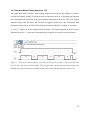

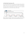

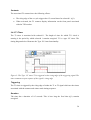
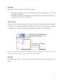


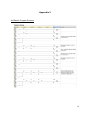
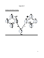


![Final Internship Report [2010]](http://vs1.manualzilla.com/store/data/005896519_1-a5f1a8e6048f4d9682b8444276c74e28-150x150.png)