1
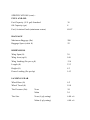
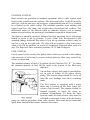
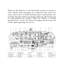
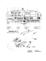
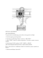
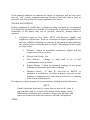
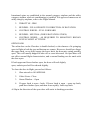
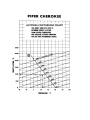
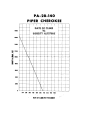
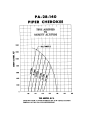
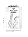
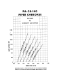
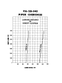
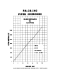
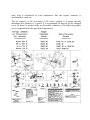
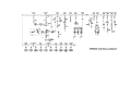
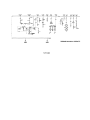
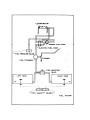
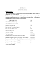
SECTION I
SPECIFICATIONS
PERFORMANCE
The gross weight of 2150 pounds in the following performance charts applies to
Serial Nos. 28-7225001 and up.
Performance figures are for standard airplanes flown at gross weight under
standard conditions at sea level, or stated altitude. Any deviation from standard
equipment may result in changes in performance.
GROSS WEIGHT
Take-off Run (ft) (flaps up)
2150
800
Take-off Distance Over 50-ft
Obstacle (ft) (flaps up)
1700
Best Rate of Climb Speed (mph)
85
Rate of Climb (ft per mm)
660
Service Ceiling (ft)
14,300
Absolute Ceiling
16,800
Top Speed (mph)
130 (142*)
Cruising Speed (75% power, sea level) (mph)
121 (124*)
Optimum Cruising Speed (75%) power, 7000 ft, mph)
132 (135*)
Instructional Power Cruise Speed (60% power, sea level) 108 (110*)
Fuel Consumption (gal per hr 75%)
8.4
Fuel Consumption (gal per hr 50%)
5.6
* With wheel fairings
SPECIFICATIONS (cont):
PERFORMANCE
GROSS WEIGHT
2150
Cruising Range (75% power, sea level, mi)
495
Cruising Range (75% power, 7000 ft, mi)
540
Optimum Cruising Range (55% power, 10.000 ft)
670
Instructional Power Cruising Range (60% power, sea level)
575
Stalling Speed (flaps down, mph)
55
Landing Roll (flaps down, ft)
535
WEIGHTS
Gross Weight (lbs)
2150
POWER PLANT
Empty Weight (Standard) (lbs)
1231
USEFUL LOAD (Standard) (lbs)
920
Engine – Lycoming
O-320-E30
Rated Horsepower and Speed (rpm)
l50 at 2700
Bore (inches)
5.125
Stroke (inches)
3.875
Displacement (cubic inches)
319.8
Compression Ratio
7:1
Dry Weight (pounds)
276
Oil Sump Capacity (qts)
8
Propeller (Sensenich)
M74DM
SPECIFICATIONS (cont).:
FUEL AND OIL
Fuel Capacity (U.S. gal) Standard
36
Oil Capacity (qts)
8
Fuel, Aviation Grade (minimum octane)
80/87
BAGGAGE
Maximum Baggage (lbs)
200
Baggage Space (cubit ft)
22
DIMENSIONS
Wing Span (ft)
30
Wing Area (sq ft)
160
Wing Loading (lbs per sq ft)
13.4
Length (ft)
23.3
Height (ft)
8.3
Power Loading (lbs per hp)
14.3
LANDING GEAR
Wheel Base (ft)
6.2
Wheel Tread (ft)
10.0
Tire Pressure (lbs)
Tire Size
Nose
24
Main
24
Nose (4 ply rating)
6.00 x 6
Main (4 ply rating)
6.00 x 6
SECTION II
DESIGN INFORMATION
Engine and Propeller
Structures
Landing Gear
Control System
Fuel System
Electrical System
Heating and Ventilating System
Cabin Features
Optional Equipment
SECTION II
DESIGN INFORMATION
ENGINE AND PROPELLER
The Lycoming O-320-E3D engine installed in the Cherokee PA-28-140 is rated
at 150 horsepower at 2700 rpm. This engine has a compression ratio of 7 to 1
and requires 80/87 minimum octane fuel. The engine is equipped with direct
drive or optional geared drive starter, a 60 ampere alternator, dual magnetos
vacuum pump drive, diaphragm type pump and a float carburetor.
Exhaust gases are carried through a system constructed of heavy gauge stainless
steel which incorporates heater shrouds to provide cabin heat, defrosting, and
carburetor deicing.
The propeller used on the PA-28-140 is a Sensenich M84DM fixed-pitch
aluminum alloy unit. Its diameter is 74 inches with a standard pitch of 58 inches.
All performance figures are based on the standard 58 inch pitch propeller.
Cowling on the Cherokee is designed to cool the engine in all normal flight
conditions, including protracted climb, without the use of cowl flaps or cooling
flanges.
The throttle quadrant is in the lower center of the instrument panel and contains
the throttle and mixture control. A friction lock on the right side of the quadrant
prevents creeping of the controls. To the right of the quadrant is the carburetor
heat control that provides maximum carburetor heat when fully ON. Air passes
through a highly efficient dry type filter when the carburetor heat is OFF.
The Flite Liner incorporates a throttle detent adjusted to the 60% power location
for the throttle control. When the throttle is set in this detent, the tachometer
needle will match the white radial decal indicating 2265 RPM on the glass of the
tachometer at 3500 feet altitude. The arcs of this decal represent 60% power at
sea level (2180 RPM) and 7000 feet (2345 RPM). Thus an economical 60%
power setting can be easily obtained up to 7000 feet altitude.
STRUCTURES
All structures are of aluminum alloy construction and are designed to ultimate
load factors well in excess of normal requirements. All exterior surfaces are
printed with etching primer and painted with acrylic lacquer.
The wings are attached to each side of the fuselage by inserting the butt ends of
the respective main spars into a spar box carry through which is an integral part
of the fuselage structure, providing, in effect, a continuous main spar with
splices at each side of the fuselage. There are also fore and aft attachments at the
rear spar and at an auxiliary front spar.
The wing airfoil section is a laminar flow type, NACA652-415 with the
maximum thickness about 40% aft of the leading edge. This permits the main
spar carry through structure to be located under the rear seat providing
unobstructed cabin floor space ahead of the rear seat.
LANDING GEAR
The three landing gears use a Cleveland 6.00 x 6 wheel, the main wheels being
provided with brake drums and Cleveland single disc hydraulic brake
assemblies. The nose wheel and the main gear both use 6.00 x 6 four ply tires.
All the tires have tubes.
The nose gear is steer able through a 44° arc by use of the rudder pedals. A
spring device is incorporated in the rudder pedal torque tube assembly to aid in
rudder centering and to provide rudder trim. The nose gear steering mechanism
also incorporates a hydraulic shimmy dampener.
The oleo struts are of the air-oil type with normal extension being 3.25 inches
for the nose gear and 4.50 inches for the main gear under normal static (empty
weight of airplane plus fuel and oil) load.
The brakes are actuated by a hand lever and a master cylinder which is located
below and near the center of the instrument panel. The toe brakes and the hand
lever have their own brake cylinders but they both use a common reservoir. The
parking brake is incorporated in the lever brake and is operated by pulling back
on the lever and depressing the knob attached to the top of the handle. To release
the parking brake, pull back on the brake lever to disengage the catch
mechanism; then allow the handle to swing forward.
CONTROL SYSTEM
Dual controls are provided as standard equipment with a cable system used
between the controls and the surfaces. The horizontal tail is of the all movable
slab type, with an anti-servo tab acting as a longitudinal trim tab. It is actuated
by a control on the cabin ceiling. The stabilator provides extra stability and
control with less size, drag, and weight than conventional tail surfaces. The
differential action of the ailerons tends to eliminate adverse yaw in turning
maneuvers and reduces the amount of coordination required in normal turns.
The flaps are manually operated, balanced for light operating forces and spring
loaded to return to the up position. A past- center lock incorporated in the
actuating linkage holds the flap when it is in the up position so that it may be
used as a step on the right side, The flap will not support a step load except
when in the full up position, so it must be completely retracted when used as a
step. The flaps have three extended positions, 10. 25 and 40 degrees.
FUEL SYSTEM
Fuel is stored in two twenty-five gallon tanks which are secured to the leading
edge structure of each wing by screws and nut plates to allow easy removal for
service or inspection.
The standard quantity of fuel is 36 gallons for the Cherokee 140 “E”. To obtain
the statidard quantity of fuel, fill the tanks to the bottom of the filler neck
indicator.
An auxiliary electric fuel pump is provided for
use in case of failure of the engine driven
pump. The electric pump should be on for all
take-offs and landings and when switching
tanks.
The fuel strainer is equipped with a quick
drain and is located on the front lower left
corner of the firewall. This strainer should be
drained regularly to check for water or
sediment accumulation. To drain the lines
from the tanks, the tank selector valve must be
switched to each tank in turn, with the electric
pump on, and the gascolator drain valve opened. Each tank has an individual
quick drain located at the bottom, inboard, rear corner.
Fuel quantity and pressure are indicated on gauges located in the engine gauge
cluster on the left side of the instrument panel.
ELECTRICAL SYSTEM
The electrical system includes a 1.2 volt 60 ampere alternator, battery, voltage
regulator, over voltage relay, and master switch relay. The battery and master
switch relay are located beneath the baggage compartment floor. Access for
service or inspection is obtained by raising the hinged floor panel. The regulator
and over voltage relay are located on the forward left side of the fuselage behind
the instrument panel.
Electrical switches are located on the right center instrument panel, and the
circuit breakers are located on the lower right instrument panel. A rheostat
switch on the right side of the switch panel controls the navigation lights and the
intensity of the instrument panel light.
Standard electrical accessories include starter, electric fuel pump, stall warning
indicator, cigar lighter, and ammeter. Navigation lights, anti-collision light,
landing light and instrument panel lighting are offered as optional accessories.
The Flite Liner includes as standard electrical accessories starter,
electrical fuel pump, stall warning indicator, ammeter, navigation
lights, anti-collision light, landing light and instrument panel
lights.
Circuit provisions are made to handle a complete complement of
communications and navigational equipment.
The alternator system offers many advantages over the gener ator
system. The main advantage is full electrical power output at much
lower engine RPM and results in improved radio and electrical
equipment operation. Since the alternator output is available all the
time, the battery will be charging almost con tinuously. This will
make cold weather starting easier.
In generator systems, the ammeter indicates battery discharge. In
the Cherokee electrical system the ammeter displays in amperes
the load placed on the alternator. With all electrical equipment
except the master switch in the OFF position, the ammeter will
indicate the amount of charging current demanded by the battery.
As each item of electrical equipment is turned on, the current will
increase to a total appearing on the ammeter. This total includes
the battery. The maximum continuous load for night flight with
radios on is about 30 amperes. This 30 ampere value plus
approximately 2 amperes for a fully charged battery will appear
continuously under these flight conditions.
The master switch is a split switch with the left half operating the
master relay and the right half energizing the alternator. The switch
is interlocked so that the alternator cannot be operated without the
battery. For normal operation, be sure both halves are turned on.
Maintenance on the alternator should prove to be a minor factor.
Should service be required, contact the local Piper Dealer. Do not
take off with a fully discharged battery as 3 volts are needed to
excite the alternator.
HEATING AND VENTILATING SYSTEM
Heat for the cabin interior and the defroster system is provided by
a heater muff attached to the exhaust system. The amount of heat
desired can be regulated with the controls located on the far right
side of the instrument panel. If unusual odors are noticed, the heat
should be shut off and the system inspected for leaks. The air flow
may be regulated between the front and rear seats by the use of the
levers located on top of the heat ducts next to the control console.
Fresh air inlets are located in the leading edge of the wing at the
intersection of the tapered and straight sections. A large adjustable
outlet is located on the side of the cabin near the floor at each seat
location, overhead air outlets are offered as optional equipment.
Cabin air is exhausted through an outlet located below the rear seat
floor panel.
On Flite Liner overhead air outlets are not offered as optional
equipment.
CABIN FEATURES
The instrument panel of the Cherokee is designed to accommo date
the customary advanced flight instruments and all the normally
required power plant instruments. The artificial horizon and
directional gyro are vacuum operated through use of a vacuum
pump installed on the engine, while the turn indicator is
electrically operated. A vacuum gauge is mounted on the far right
side of the instrument panel. A natural separation of the flight
group and power group is provided by placing the flight group in
the upper instrument panel and the power group in the sub-panel
centre. The radios and circuit breakers located on the right hand
instrument panel have extra circuits provided for a complete line of
optional radio equipment. The microphone is located on the
console cover, see illustration, page 15, item 39 and page 10, item
20.
The front seats are adjustable fore and aft, and recline for pilotpassenger comfort and ease of entry and exit. A family seat
installation is available which provides two additional seats. Each
family seat is capable of carrying a full size adult which gives the
Cherokee 140 “E”, 4-place capacity. Optional headrests and
vertically adjustable front seats are also available.
A single strap shoulder harness controlled by an inertia reel is
standard equipment for the front seats, and is offered as an option
for the rear seats when they are installed. The shoulder strap is
routed over the shoulder adjucent to the windows and attached to
the inboard lap strap in the general area of the occupant’s inboard
hip.
A check of the inertia reel mechanism is made by pulling sharply
on the strap. The reel will lock in place under this rest and prevent
the strap from extending. Under normal movement the strap will
extend and retract as required.
The Flite Liner has all of the above features except, there is only
one radio installed, optional headrests, vertically adjustable front
seats, and family seats are not available.
AIR CONDITIONING*
The air conditioning system is a recirculating air system. The
major items include evaporator, condenser, compressor, blower,
switches and temperature controls.
The evaporator is located behind the left rear side of the baggage
compartment. This cools the air that is used for air conditioning.
The condenser is mounted on a retractable scoop located on the
bottom of the fuselage and to the rear of the baggage compartment
area. The scoop extends when the air conditioner is “ON” and
retracts to a flush position when the system is ‘OFF”.
The compressor is mounted on the forward right underside of the
engine. It has an electric clutch which automatically engages or
disengages the compressor to the belt drive system of the
compressor.
An electrical blower is mounted on the aft side of the rear cabin
panel. Air from the baggage area is drawn through the evaporator
by the blower and distributed through an overhead duct to
individual outlets located adjacent to each occupant.
The switches and temperature control are located on the lower
right side of the instrument panel in the climate control center
panel. The temperature control regulates the desired temperature of
the cabin. Turn the control clockwise for increased cooling,
counterclockwise for decreased cooling.
Located inboard of the temperature control is the air conditioner
master switch. The switch has three positions: “FAN ONLY”,
“OFF” and “AIR COND.” When “AIR COND” is selected the
compressor clutch engages, the condenser scoop opens and the fan
is turned on. Cooling air should be felt within one minute.
NOTE
If the system is not operating in 5 minutes turn the
system “OFF,” until the fault is corrected.
The “FAN ONLY” position allows operation of the fan with the
air conditioner turned “OFF” to aid cabin air circulation if desired.
The “FAN” switch allows selecting a “LOW,” “MED” or “HIGH”
flow of air to the air conditioner outlets located in the over head
duct. The outlets can be adjusted or turned off by each occupant to
obtain individual cooling effect.
There are two indicator lights associated with the air condition er.
On early models both lights are located below the switch on the air
conditioner panel. On the later version the “Door Open” indicator
light is located on the left side of the instrument panel. The
“FUSE” light illuminates to indicate failure of one or both of the
fuses which protect the control circuits. The fuses are located
behind the climate control center panel.
The “Door Open Light” illuminates whenever the condenser door
is open and remains on until the door is closed.
A circuit breaker located on the circuit breaker panel protects the
air conditioning electrical system.
Whenever the throttle is in the full throttle position, it actuates a
micro switch which disengages the compressor and retracts the
scoop. This is done to obtain maximum power and maximum rate
of climb. The fan continues to operate and the air will remain cool
for approximately one minute. When the throttle is retarded
approximately 1/4 inch, the clutch will engage and the scoop will
extend, again supplying cool, dry air.
SECTION III
OPERATING INSTRUCTIONS
PREFLIGHT
The airplane should be given a thorough visual inspection prior to each flight.
Particular attention should be given to the following items
1.
a. Remove control lock.
b. Master switch ON.
c. Check fuel quantity indicators (two tanks).
d. Master switch and ignition OFF.
2.
a. Check for external damage, operational interference of control
surfaces or hinges.
b. Insure that wings and control surfaces are free of snow, ice or frost.
3.
a. Visually check fuel supply, secure caps.
b. Drain all fuel system sumps and lines.
c. Check that fuel system vents are open.
4.
a. Check landing gear shock struts for proper inflation.
b. Check tires for cuts, wear and proper inflation.
c. Check brake blocks and discs for wear and damage.
5.
a. Inspect windshield for cleanliness.
b. Check the propeller and spinner for defects or nicks.
c. Check for obvious fuel or oil leaks.
d. Check oil level, 8 quarts maximum. (Insure dipstick is properly
seated).
e. Inspect cowling and inspection covers for security.
f. Check nose wheel tire for inflation, wear.
g. Check nose wheel shock strut for proper inflation.
h. Check for foreign matter in air inlets.
6.
a. Stow tow bar and control locks, if used.
b. Check baggage for proper storage and security.
c. Close and secure the baggage compartment door.
7.
a. Upon entering aircraft ascertain that all primary flight controls
operate properly.
b. Close and secure the cabin door.
c. Check that required papers are in order and in the aircraft.
d. Fasten seat belts and shoulder harness. Check function of inertia reel.
STARTING ENGINE
1.
Set parking brake ON.
2.
Set the carburetor heat control in the full COLD (OFF) position.
3.
Select the desired tank with fuel selector valve.
Starting Engine When Cold:
1.
Open throttle approximately 1/4 inch.
2.
Turn the master switch ON.
3.
Turn the electric fuel pump ON.
4.
Move the mixture control to FULL RICH.
5.
Engage the starter by rotating magneto switch clockwise and pressing
in.
6.
When the engine fires, advance throttle to desired setting. If the engine
does not fire within five to ten seconds, disengage starter and prime
with one to three strokes of the priming pump. Repeat the starting
procedure.
Starting Engine When Hot:
1.
Open the throttle approximately 1/2 inch.
2.
Turn the master switch ON.
3.
Turn the electric fuel pump ON.
4.
Put mixture control in IDLE CUT-OFF.
5.
Engage the starter by rotating magneto switch clockwise and pressing
in. When the engine fires, advance the mixture control and move the
throttle to desired setting.
Starting Engine When Flooded:
1.
Open the throttle full.
2.
Turn the master switch ON.
3.
Turn the electric fuel pump OFF.
4.
Put mixture control in IDLE CUT-OFF.
5.
Engage the starter by rotating magneto switch clockwise and pressing
in. When the engine fires, advance the mixture control and retard the
throttle.
When the engine is firing evenly, advance the throttle to 800 RPM. If oil
pressure is not indicated within thirty seconds, stop the engine and determine the
trouble. In cold weather it will take a few seconds longer to get an oil pressure
indication. If the engine has failed to start, refer to the “Lycoming Operating
Handbook, Engine Troubles and Their Remedies”.
Starter manufacturers recommend that cranking periods be limited to thirty
seconds with a two minute rest between cranking periods. Longer cranking
periods will shorten the life of the starter.
WARM-UP
As soon as the engine starts, the oil pressure should be checked. If no pressure is
indicated within thirty seconds, stop the engine and determine the trouble. In
cold weather it will take a few seconds longer to get an oil pressure indication.
Warm-up the engine at 800 to 1200 RPM.
Take-off may be made as soon as ground check is completed, providing that the
throttle may be opened fully without back firing or skipping and without
reduction in engine oil pressure.
GROUND CHECK
Check the magnetos at 2000 RPM by switching from Both to Right then back to
Both before switching to Left. Differential drop should not exceed 50 RPM
while the total drop on either magneto should not exceed 175 RPM.
Check both the oil temperature and pressure. The temperature may be low for
some time if the engine is being run for the first time of the day, but as long as
the pressure is within limits the engine is ready for take-off.
Carburetor heat should also be checked prior to take-off to be sure that the
control is operating properly and to clear any ice which may have formed during
taxing. Avoid prolonged ground operation with carburetor heat ON as the air is
unfiltered.
Operation of the engine driven fuel pump should be checked while taxiing or
during pretake-off engine run up by switching off the electric fuel pump and
observing fuel pressure. The electric fuel pump should be on during take-off to
prevent loss of power should the engine driven pump fail. The engine is warm
enough for take off when the throttle can be opened without the engine faltering.
For air conditioner ground check refer to page 31.
TAKE-OFF
Just before take-off the following items should be checked:
1. Fuel on proper tank
2. Electric fuel pump – on
3. Engine gauges checked
4. Flaps - set
5. Carb. heat off
6. Mixture - set
7. Seat backs erect
8. Fasten belts/harness
9. Trim tab – set
10. Control - free
11. Door – latched
12. Air conditioner - off
In the conventional take-off procedure set the trim control slightly aft of neutral.
Allow the airplane to accelerate to 50 to 60 miles per hour, then ease back on the
wheel enough to let the air plane fly itself from the ground. Premature or
excessive raising of the nose will result in a delayed take-off. After take-off let
the air craft accelerate to the desired climb speed by lowering the nose slightly.
Short Field, Obstacle Clearance:
Lower the flaps to 25° (second notch), accelerate to 55-60 miles per hour and
ease back on the control wheel to rotate. After break ing ground, accelerate to
the best angle of climb speed, 74 miles per hour. Slowly retract the flaps when
the obstacle has been cleared and continue climb at 85 miles per hour.
Short Field, No Obstacles:
Lower the flaps to 25° (second notch) accelerate to 55-60 miles per hour. Ease
back on the control wheel to rotate and accelerate to best rate of climb speed, 85
miles per hour. Slowly retract the flaps while climbing out.
Soft Field, No Obstacles:
Lower flaps to 25°. (second notch), accelerate aircraft, pull nose gear from the
ground as soon as possible, lift off at lowest possible airspeed. Accelerate just
above the ground to best rate of climb speed, 85 miles per hour. Climb out while
slowly retracting the flaps.
Soft Field, Obstacle Clearance:
Lower the flaps 25o (second notch), accelerate aircraft and nose gear off as soon
as possible and lift off at lowest possible air speed. Accelerate just above the
ground to best angle of climb speed, 74 miles per hour to climb past obstacle
clearance height, continue climb while accelerating to best rate of climb speed,
85 miles per hour and slowly retract the flaps.
CLIMB
The best rate of climb airspeed at gross weight is 85 miles per hour while the
best angle of climb airspeed is 74 miles per hour. At lighter than gross weight
these speeds are reduced. The recommend ed enroute climbing speed of 100
miles per hour provides increased visibility over the nose. Shallow turns of a
few degrees will also aid forward visibility during climb out. The air conditioner
may be turned on after all obstacles have been cleared.
STALLS
Stall characteristics of the Cherokee are conventional. Visual stall warning is
provided by a red light located on the left side of the instrument panel which is
turned on automatically between 5 and 10 miles per hour above stall speed.
Gross weight stalling speed with power off and full flaps is 55 miles per hour at
2150 pounds. With flaps up this speed is increased 9 miles per hour.
Intentional spins are prohibited in the normal category airplane. Lazy eights and
chandelles may be performed in the normal category provided a 60° angle of
bank and/or a 30° angle of pitch is not exceeded. For approved maneuvers and
entry speeds refer to the Flight Manual.
CRUISING
The cruising speed is determined by many factors including power setting,
altitude, temperature, loading and equipment installed on the airplane.
The normal cruising power is 75% of the rated horsepower of the engine. True
airspeeds which may be obtained at various altitudes and power settings can be
determined from the charts in Section IV of this handbook.
Use of the mixture control in cruising flight reduces fuel consumption
significantly, especially at higher altitudes. The mixture should be leaned during
cruising operation above 5000 feet altitude and at pilot’s discretion at lower
altitudes when 75% power or lean is being used. If any doubt exists as to the
amount of power being used, the mixture should be in the FULL RICH position
for all operations under 5000 feet.
To lean the mixture, pull the mixture control until the engine becomes rough,
indicating that the lean mixture limit has been reached in the leaner cylinders.
Then enrich the mixture by pushing the control towards the instrument panel
until engine operation be comes smooth.
The continuous use of carburetor heat during cruising flight decreases engine
efficiency. Unless icing conditions in the carburetor are severe, do not cruise
with the heat on. Apply full carburetor heat slowly and only for a few seconds at
intervals determined by icing severity.
In order to keep the airplane in best lateral trim during cruising flight, the fuel
should be used alternately from each main tank. It is recommended that one
main tank be used for one hour after take
-off; the other main tank used until nearly exhausted, then return to the first
main tank.
MANEUVERS
The airplane is approved for certain aerobatic maneuvers, provided it is loaded
within the approved weight and center of gravity limits. (See Airplane Flight
Manual). The maneuvers are spins, steep turns, lazy eights and chandelles. Spins
are prohibited when air conditioning is installed.
APPROACH AND LANDING
Landing check list:
1. Fuel on proper tank
2. Mixture - rich
3. Elec. fuel pump on
4. Seat backs erect
5. Flaps-set (115 MPH)
6. Fasten belts/harness
7. Air conditioner - off
The airplane should be trimmed to an approach speed of about 85 miles per hour
with flaps up. The flaps can be lowered at speeds up to 115 miles per hour,
approach speed is reduced 3 miles per hour for each notch of flaps used.
Carburetor heat should not be applied unless there is an indication of carburetor
icing, since the use of carburetor heat causes a reduction in power which may be
critical in case of a go-around. Full throttle operation with carburetor heat on is
likely to cause detonation.
The amount of flap used during landings and the speed of the aircraft at contact
with the runway should be varied according to the landing surface and existing
conditions, both wind wise and load wise. It is generally good practice to contact
the ground at the minimum possible safe speed consistent with existing
conditions.
Normally, the best technique for short and slow landings is to use full flap and
enough power to maintain the desired airspeed and approach flight path. Mixture
should be full rich, fuel on the fullest tank, carburetor heat off, and electric fuel
pump on. Reduce the speed during the flare out and contact the ground close to
the stalling speed (55 to 65 MPH). After ground contact hold the nose wheel off
as long as possible. As the airplane slows down, drop the nose and apply the
brakes. There will be less chance of skidding the tires if the flaps are retracted
before applying the brakes. Braking is most effective when back pressure is
applied to the control wheel, putting most of the aircraft weight on the main
wheels. In high wind conditions, particularly in strong crosswinds, it may be
desirable to approach the ground at higher than normal speeds with partial or no
flaps.
STOPPING ENGINE
At the pilot’s discretion, the flaps should be raised and the electric fuel pump
turned off. After parking, the air conditioner and radios should be turned off and
the engine stopped by pulling the mixture control to idle cut-off. The throttle
should be left full aft to avoid engine vibration while stopping. Then the
magneto and master switches should be turned off.
MOORING
The Cherokee should be moved on the ground with the aid of the nose wheel
tow bar provided with each plane and secured in the baggage compartment. Tie
downs may be secured to rings provided under each wing, and to the tail skid.
The aileron and stabilator control wheel shaft, see page 30. The rudder is held in
position by its connections to the nose wheel steering, and normally does not
have to be secured. The flaps are locked when in the full up position, and should
be left retracted.
WEIGHT AND BALANCE
It is the responsibility of the owner and pilot to determine that the airplane
remains within the allowable weight vs. center of gravity envelope while in
flight. For weight and balance data see the Airplane Flight Manual and Weight
and Balance Form supplied with each airplane.
OPERATING TIPS
The following Operating Tips are of particular value in the operation of the
Cherokee 140 “E”.
1.
Learn to trim for take-off so that only a very light back pressure on the
wheel is required to lift the airplane off the ground
2.
The best speed for take-off is about 60 MPH under normal conditions.
Trying to pull the airplane off the ground at too low an airspeed
decreases the controllability of the airplane in event of engine failure.
3.
Flaps may be lowered at airspeeds up to 115 MPH. To reduce flap
operating loads, it is desirable to have the airplane at a slower speed
before extending the flaps.
4.
Before attempting to reset any circuit breaker, allow a two to five
minute cooling off period.
5.
Before starting the engine, check that all radio switches, light switches,
and the pitot heat switch are in the off position so as not to create an
overloaded condition when the starter is engaged.
6.
The overvoltage relay is provided to protect the electronics equipment
from a momentary overvoltage condition (approximately 16.5 volts and
up), or a catastrophic regulator failure. In the event of a momentary
condition, the relay will open and the ammeter will indicate “0” output
from the alternator. The relay may be reset by switching the ALT
switch to OFF for approximately 30 seconds and then returning the
ALT switch to ON. If after recycling the ALT switch the condition
persists, the flight should be terminated as soon as practical, reduce the
battery load to a minimum.
7.
The vacuum gauge is provided to monitor the pressure available to
assure the correct operating speed of the vacuum driven gyroscopic
flight instruments, it also monitors the condition of the common air
filter by measuring the flow of air thru the filter.
If the vacuum gauge registers lower than 5” — .10” Hg at 2000 RPM, the
following items should be checked before flight:
a. Common air filter could be dirty or restricted.
b. Vacuum lines could be collapsed or broken.
c. Vacuum pump, worn.
d. Vacuum regulator, not adjusted correctly. The pressure, even though
set correctly, can read lower under two conditions: (1) Very high altitude, above
12000 feet, (2) Low engine RPM usually on approach or during training
maneuvers. This is normal and should not be considered a malfunction.
OPTIONAL EQUIPMENT
AIR CONDITIONING
To operate the air conditioning system either on the ground or in flight:
1. Start the engine (ground operation).
2. Turn the air conditioning “Master” switch to “AIR COND.”
3. Turn “TEMP” control to desired temperature. Clockwise rotation increases
cooling.
4. Select desired “FAN” position, ‘LOW”, “MED” or “HIGH.”
AIR CONDITIONER OPERATIONAL CHECK PROCEDURE
Prior to take-off the air conditioner should be checked for proper operation as
follows:
1. Check aircraft Master Switch ON.
2. Turn the air conditioner control switch “AIR COND.” - the “Air Cond. Door
Open” warning light will turn on, thereby indicating proper air conditioner
condenser door actuation.
3. Turn the air conditioner control switch to “OFF” - the “Air Cond. Door Open”
warning light will go out, thereby indicating the air conditioner condenser door
is in the up position.
4. If the “Air Cond. Door Open” light does not respond as specified above, an
air conditioner system or indicator bulb
malfunction is indicated, and further investigation should be conducted prior to
flight.
The above operational check may be performed during flight if an in flight
failure is suspected.
AIR CONDITIONER EFFECTS ON AIRPLANE PERFORMANCE
Operation of the air conditioner will cause slight decreases in the cruise speed
and range of the Cherokee 140. Power from the engine is required to run the
compressor, and the condenser door, when extended, causes a slight increase in
drag. When the air conditioner is turned off there is normally no measurable
difference in climb, cruise or range performance of the airplane.
NOTE
To insure maximum climb performance the air conditioner must
be turned off manually before take-off to disengage the
compressor and retract the condenser door. Also the air
conditioner must be turned off manually before the landing
approach in preparation for a possible go-around.
Although the cruise speed and range are only slightly affected by
the air conditioner operation, these changes should be considered
in preflight planning. To be conservative, the following figures
assume that the compressor is operating continuously while the
airplane is airborne. This will be the case only in extremely hot
weather.
1. The decrease in the airspeed is approximately 5 mph at 75% power and 4 mph
at 50% power.
2. The decrease in range may be as much as 28 statue miles for the 36 gal.
(standard) capacity and as much as 39 statute miles for the 50 gal. (reserve)
capacity.
NOTE
To read power from the Power vs. Density Altitude Chart in this
manual, add 50 rpm to the value observed on the tachometer
when the air conditioner is operating.
The climb performance of Cherokee 140 is not compromised measurably with
the air conditioner operating since the compressor is de-clutched and the
condenser door is retracted, both automatically, when a full throttle position is
selected. When the full throttle position is not used or in the event of a
malfunction which caused the compressor to operate and the condenser door to
be extended, a decrease in rate of climb of as much as 100 fpm can be expected.
Should a malfunction occur which prevents condenser door retraction when the
compressor is turned off, a decrease in rate of climb of as much as 50 fpm can
be expected.
SECTION IV
EMERGENCY PROCEDURES
INTRODUCTION
This section contains procedures that are recommended if an emergency
condition should occur during ground operation, take-off, or in flight. These
procedures are suggested as the best course of action for coping with the
particular condition described, but are not a substitute for sound judgment and
common sense. Since emergencies rarely happen in modern aircraft, their
occurrence is usually unexpected, and the best corrective action may not always
be obvious. Pilots should familiarize themselves with the procedures given in
this section and be prepared to take appropriate action should an emergency
arise.
Most basic emergency procedures, such as power off landings, are a part of
normal pilot training. Although these emergencies are discussed herein, this
information is not intended to replace such training, but only to provide a source
of reference and review, and to provide information on procedures which are not
the same for all aircraft. It is suggested that the pilots review standard
emergency procedures periodically to remain proficient in them.
In the procedures that follow, critical actions with respect to time are indicated
by the use of bold print; these actions should be performed immediately if the
emergency condition is not to be aggravated. The remaining procedures are noncritical in the sense that time is usually available for consulting the check list.
GROUND OPERATIONS
ENGINE FIRE DURING START
Engine fires during start are usually the result of over priming. The procedures
below are designed to draw the excess fuel back into the induction system:
1. STARTER - CONTINUE TO CRANK ENGINE
2. THROTTLE - OPEN
3. MIXTURE - IDLE CUT-OFF
4. ELECTRIC FUEL PUMP - OFF
5. FUEL SELECTOR - OFF (if time allows)
6. ABANDON AIRCRAFT IF FIRE CONTINUES
TAKE-OFF
ENGINE POWER LOSS DURING TAKE-OFF
The proper action to be taken if loss of power occurs during take-off will depend
on circumstances.
1.
If sufficient runway remains for a normal landing, land straight ahead.
2.
If insufficient runway remains, maintain a safe airspeed and make only
a shallow turn to avoid obstructions. Use of flaps depends on
circumstances. Normally, flaps should be fully extended for
touchdown.
3.
If you have gained sufficient altitude to attempt a re start, proceed as
follows:
a.
MAINTAIN SAFE AIRSPEED
b.
FUEL SELECTOR - SWITCH TO ANOTHER TANK
CONTAINING FUEL
c.
ELECTRIC FUEL PUMP - CHECK ON
d.
MIXTURE - CHECK RICH
e.
CARBURETOR HEAT - ON
NOTE
If engine failure was caused by fuel exhaustion, power will not
be regained after tanks are switched until empty fuel lines are
filled, which may require up to ten seconds.
If power is not regained, proceed with the POWER OFF LANDING procedure.
IN FLIGHT
ENGINE POWER LOSS IN-FLIGHT
Complete engine power loss is usually caused by fuel flow interruption, and
power will be restored shortly after fuel flow is restored. If power loss occurs at
low altitude, the first step is to prepare for an emergency landing (See POWER
OFF LANDING). Maintain an airspeed of at least 80 MPH lAS, and if altitude
permits, proceed as follows:
1.
Fuel Selector - switch to another tank containing fuel.
2.
Electric Fuel Pump - On
3.
Mixture - Rich
4.
Carburetor Heat - On
5.
Engine Gauges - check for an indication of the cause of Power Loss.
6.
Primer - Check Locked
7.
If no fuel pressure is indicated, check tank selector position to be sure it
is on a tank containing fuel.
When Power is Restored:
8.
Carburetor Heat - Off
9.
Electric Fuel Pump - Off
If the above steps do not restore power, prepare for an emergency landing. If
time permits:
1.
Ignition Switch - “L” then “R” then back to “BOTH”.
2.
Throttle and Mixture - Different settings. (This may restore power if
problem is too rich or too lean a mixture, or partial fuel system
restriction).
3.
Try another fuel tank - (Water in the fuel could take some time to be
used up, and allowing the engine to windmill may restore power. If
power loss is due to water, fuel pressure indications will be normal).
NOTE
If engine failure was caused by fuel exhaustion, power will not
be regained after tanks are switched until empty fuel lines are
filled, which may require up to ten seconds.
If power is not restored, proceed with POWER OFF LANDING
procedures.
POWER OFF LANDING
If loss of power occurs at altitude, trim the aircraft for best gliding angle (80
MPH lAS) (Air Cond. Off) and look for a suit able field. If measures taken to
restore power are not effective, and if time permits, check your charts for
airports in the immediate vicinity; it may be possible to land at one if you have
sufficient altitude. If possible, notify the FAA by radio of your difficulty and
intentions. If another pilot or passenger is aboard, let them help.
When you have located a suitable field, establish a spiral pat terns around this
field. Try to be at 1000 feet above the field at the downwind position, to make a
normal approach. Excess altitude may be lost by widening your pattern, using
flaps or slipping, or a combination of these.
Touchdowns should normally be made at the lowest possible airspeed, with full
flaps.
When committed to landing:
1.
Ignition - Off
2.
Master Switch - Off
3.
Fuel Selector - Off
4.
Mixture - Idle Cut-Off
5.
Seat Belt Tight, Shoulder Harness in Place
FIRE
There is no fire detection system on the aircraft. The presence of fire is noted
through smoke, smell, and heat in the cabin. It is essential that the source of the
fire be promptly identified through instrument readings, character of the smoke,
or other indications, since the action to be taken differs somewhat in each case.
1.
Source of fire - Check
Electrical Fire (smoke in cabin):
2.
Master Switch - Off
3.
Vents - Open
4.
Cabin Heat - Off
5.
Land as soon as practicable.
Engine Fire
1.
Mixture Control - Idle cut-off
2.
Fuel Selector - Off
3.
Electric Fuel Pump - Check Off
4.
Master Switch - Off
5.
Magneto Switch - Off
6.
Throttle - Closed
7.
Dive to blow out fire (if altitude permits).
Proceed with POWER OFF LANDING procedure.
LOSS OF OIL PRESSURE
Loss of oil pressure may be either partial or complete. A partial loss of oil
pressure usually indicates a malfunction in the oil pres sure regulating system,
and a landing should be made as soon as possible to investigate the cause, and
prevent engine damage.
A complete loss of oil pressure indication may signify oil exhaustion or may be
the result of a faulty gauge. In either case, proceed toward the nearest airport,
and be prepared for a forced landing. If the problem is not a pressure gauge
malfunction, the engine may stop suddenly. Maintain altitude until such time as
a dead stick landing can be accomplished. Don’t change power settings
unnecessarily, as this may hasten complete power loss.
Depending on the circumstances, it may be advisable to make an off airport
landing while power is still available, particularly if other indications of actual
oil pressure loss, such as sudden increase in temperatures, or oil smoke, are
apparent, and an airport is not close.
If engine stoppage occurs, proceed to POWER OFF LANDING.
LOSS OF FUEL PRESSURE
1. Electric boost pump - On
2. Fuel Selector - Check on Full Tank
If problem is not an empty fuel tank, land as soon as practicable, and have
engine driven fuel pump checked.
HIGH OIL TEMPERATURE
An abnormally high oil temperature indication may be caused by a low oil level,
an obstruction in the oil cooler, damaged or improper baffle seals, a defective
gauge, or other causes. Land as soon as practicable at an appropriate airport and
have the cause investigated.
A steady rapid rise in oil temperature is a sign of trouble. Land at the nearest
airport and let a mechanic investigate the problem. Watch the oil pressure gauge
for an accompanying loss of pressure.
ALTERNATOR FAILURE
Loss of alternator output is detected through a zero reading on the ammeter.
Before executing the following procedure, insure that the reading is zero and not
merely low by actuating an electrically powered device, such as the landing
light. If no increase in the ammeter reading is noted, alternator failure can be
assumed.
1.
Deduce electrical load.
2.
Alternator circuit breakers - Check
3.
“Alt” swich- Off (for 30 seconds), Then On.
If the ammeter continues to indicate no output, or alternator will not stay reset,
turn off “Alt” switch, maintain minimum electrical load and land as soon as
practical. All electrical load is being supplied by the battery.
ENGINE ROUGHNESS
Engine roughness is usually due to carburetor icing, and may be accompanied
by a slight loss of airspeed or altitude. If too much ice is allowed to accumulate,
restoration of full power may not be possible; therefore, prompt action is
required.
1.
Carburetor heat-on (See Note). RPM will decrease slightly and
roughness will increase. Wait for a decrease in engine roughness or an
increase in RPM, indicating ice removal. If no change in approximately
one minute, return carburetor heat to COLD. If the engine is still rough,
try steps below.
a.
Mixture - Adjust for maximum smoothness. Engine will run
rough if too rich or too lean.
b.
Electric Fuel Pump - On
c.
Fuel Selector - Change to other tank to see if fuel
contamination is the problem.
d.
Engine Gauges - Check for abnormal readings. If any gauge
readings are abnormal, proceed accordingly.
e.
Magneto Switch - “L” then “R”, then back to “BOTH”. If
operation is satisfactory on either magneto, proceed on that
magneto at reduced power, with mixture full rich, to a landing
at the first available airport.
If roughness persists, prepare for a precautionary landing at pilots discretion.
NOTE
Partial carburetor heat may be worse than no heat at all, since it
may partially melt ice, which will refreeze in the intake system.
When using carburetor heat, therefore, always use full heat, and
when ice is removed return the control to the full cold position.
SPINS
Intentional spins are prohibited in the normal category airplane and the utility
category airplane when air conditioning is installed. Por approved maneuvers as
utility category airplane, refer to the Flight Manual.
2.
THROTTLE - IDLE
3.
RUDDER - FULL OPPOSITE TO DIRECTION OF ROTATION
4.
CONTROL WHEEL - FULL FORWARD
5.
RUDDER - NEUTRAL (WHEN ROTATION STOPS).
6.
CONTROL WHEEL - AS REQUIRED TO SMOOTHLY REGAIN
LEVEL FLIGHT ATTITUDE.
OPEN DOOR
The cabin door on the Cherokee is double latched, so the chances of it springing
open in flight at both the top and bottom are remote. However, should you forget
the upper latch, or not fully engage the lower latch, the door may spring partially
open. This will usually happen at take-off or soon afterward. An open door will
not affect normal flight characteristics, and a normal landing can be made with
the door open.
If both upper and lower latches open, the door will trail slightly
open, and airspeed will be reduced slightly.
To close the door in flight, proceed as follows:
1.
Slow aircraft to 100 MPH lAS.
2.
Cabin Vents - Close
3.
Storm Window – Open
4.
If upper latch is open - latch. If lower latch is open – open top latch,
push door further open, and then close rapidly. Latch top latch.
A Slip in the direction of the open door will assist in latching procedure.
SECTION VI
GENERAL MAINTENANCE
This section contains information for minor maintenance of the airplane. For
further maintenance assistance refer to the Cherokee 140 “E” Service Manual.
Any complex repairs or modification should be accomplished by a Piper
Certified Service Center or equivalent.
TIRE INFLATION
For maximum service from the tires, inflate them to the proper pressure of 24
pounds for all three wheels. Interchange the tires on the main wheels, if
necessary, to produce even wear. All wheels and tires are balanced before
original installation, and the relationship of the tire, tube and wheel should be
maintained, if at all possible. Out of balance wheels can cause extreme vibration
on take-off. In the installation of new components, it may be necessary to
rebalance the wheel with the tires mounted.
BATTERY SERVICE
The 12 volt battery is located in a stainless steel container under the baggage
compartment floor. This container should be drained occasionally by opening
the rubber cap on the drain tube. Check the battery for proper fluid level (below
the baffle plates) and use a hydrometer to determine the density of the battery
fluid.
If the battery is discharged, charge it before take-off as three volts are needed to
excite the alternator. To recharge, start at a 4 ampere rate and finish a 2 ampere
rate. Quick charges are not recommended.
BRAKE SERVICE
The brake system is filled with MIL-H-5606 (petroleHm base) hydraulic fluid.
This should be checked at every 100 hour inspection and replenished when
necessary by filling the brake reservoir on the firewall to the indicated level. If
the system as a whole has to be refilled with fluid, this should be done by filling
with the fluid under pressure from the brake end of the system. This will
eliminate air from the system as it is being filled.
If after extended service the brake blocks become worn excessively, they are
easily replaced with new segments. Brake clearances require no adjustments.
LANDING GEAR SERVICE
Main wheels are easily removed by taking off the hub cap, axle nut, and the two
bolts holding the brake segment in place, after which the wheels slips easily
from the axle. Tires are removed from the wheels by first deflating the tire,
removing the three through bolts, and separating the wheel halves.
Landing gear oleo struts should be checked for proper strut exposures and fluid
leaks. The required extensions for the strut when under normal static load
(empty weight of airplane plus full fuel and oil) is 3.25 inches for the nose gear
and 4.50 inches for the main gear. Should the strut exposure be below that
required, it should be determined whether air or oil is required by first raising
the airplane on jacks. Depress the valve core to allow air to escape from the strut
housing chamber. Remove the filler plug and slowly raise the strut to full
compression. If the strut has sufficient fluid it will be visible up to the bottom of
the filler plug hole and will then only require proper inflation.
Should fluid be below the bottom of the filler plug hole, oil should be added.
Replace the plug with valve core removed, attach a clear plastic hose to the
valve stem of the filler plug and submerge the other end in a container of
hydraulic fluid (MIL-H-5606). Fully compress and extend the strut several times
thus drawing fluid from the container and expelling air from the strut chamber.
To allow fluid to enter the bottom chamber of the main gear strut housing, the
torque link assembly must be disconnected to let the strut be extended a
minimum of 10 inches. (The nose gear) torque links need not be disconnected.)
Do not allow the strut to extend more than 12 inches. When air bubbles cease to
flow through the hose, compress the strut fully and again check fluid level.
Reinstall the valve core and filler plug, and the main gear torque links if
disconnected. With fluid in the strut housing at the correct level, attach a strut
pump to the air valve and inflate the oleo strut to the correct height when the
airplane is on the ground.
In jacking the airplane for landing gear or other servicing use two hydraulic
jacks and a t stand. Place 350 pounds of ballast on the base of the tail stand
before jacking up the airplane. The hydraulic jacks should be placed under the
jack points on the bot tom of the wing and the airplane should be jacked up until
the tail skid is at the correct height to attach the tail stand. With the tail stand
attached continue raising the airplane to the desired height.
FUEL AND OIL REQUIREMENTS
Aviation grade 80/87 Octane (minimum) fuel must be used in this aircraft. The
use of lower grades can cause serious engine damage in a very short period of
time, and is considered of such importance that the engine warranty is
invalidated by such use.
The oil capacity of the Lycoming 0-320 series engines is 8 quarts and the
minimum safe quantity is 2 quarts. It is recommend ed that the oil be changed
every 50 hours or sooner under un favorable conditions. The following grades
are recommended for the specified temperatures
CARE OF AIR FILTER
The carburetor air filter must be cleaned at least once every 50 hours. Under
extremely adverse conditions of operation it may be necessary to clean the filter
daily. Extra filters are inexpensive and a spare should be kept on hand and used
as a rapid replacement.
The filter manufacturer recommends that the filter be tapped gently to remove
dirt particles. Do not blow out with compressed air.
CARE OF WINDSHIELD AND WINDOWS
A certain amount of care is needed to keep the plexiglas windows clean and
unmarred. The following procedure is re commended:
1.
Flush with clean water and dislodge excess dirt, mud, etc. with your
hand.
2.
Wash with mild soap and water. Use a soft cloth or sponge, do not rub.
3.
Remove oil, grease or sealing compounds with a soft cloth and
kerosene.
4.
After cleaning, apply a thin coat of hard polishing wax. Rub lightly
with a soft cloth.
5.
A severe scratch or mar may be removed by using jeweler’s rouge to
rub out the scratch, smoothing, and then applying wax.
LEVELING AND RIGGING
Leveling the aircraft for purposes of weighing or rigging is accomplished as
follows:
1.
Partially withdraw two machine screws located immediately below the
left front side window. These screws are leveling points and the
airplane is longitudinally level when a level placed on the heads of
these screws indicates level.
2.
To put the airplane in a longitudinally level position on scales, first
block the main gear oleos in the fully extended position, then deflate
the nose wheel tire until the proper attitude is obtained. For rigging
only, the airplane may be placed on jacks for leveling.
3.
To level the airplane laterally, place a level across the baggage
compartment floor along the rear bulkhead. -
Rigging: Although the fixed flight surfaces cannot be adjusted for rigging
purposes, it may be necessary upon occasion to check the position of these
surfaces. The movable surfaces all have adjustable stops, as well as adjustable
turnbuckles on the cables or push-pull tubes, so that their range of travel can be
altered. The positions and angular travels of the various surfaces are as follows:
1.
Wings: 70 dihedral, 2° washout.
2.
Stabilator Travel: 18° up, 2° down, tolerance ±10.
3.
Fin should be vertical and in line with center of fuselage.
4.
Aileron Travel: 300 up, 150 down, tolerance ±2°.
5.
Flap Travel 100, 25°, 400 tolerance ±2°.
6.
Rudder Travel: 27° right and left,tolerance ±2°.
7.
Stabilator Tab Travel: 30 up, 12° down, tolerance ±1°.
Cable tensions for the various controls are as follows:
Rudder: 40 ±5 lbs. Stabilator: 40 ±5 lbs.
Ailerons: 40 ±5 lbs. Stabilator Trim: 10±1 lb.
Flaps: 10±1 lb.
SERIAL NUMBER PLATE
The serial number plate is located near the stabilator on the left side of the
airplane and also at the cabin entrance. Refer to this number for service or
warranty matters.