1
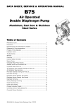
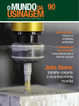
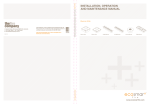
SERVICE & OPERATING MANUAL
®
Model X75 Metallic Design Level 1
U.S. Patent #
5,996,627; 6,241,487
Other U.S. Patents
Applied for
I M2
c/b2T5
See
pages
& 23
forIIATEX
2GDmarkings.
b T5
CE
Table of Contents
Engineering Data and Temperature Limitations .................................................. 1
Typical Code ......................................................................................................... 2
Material
Material Codes....................................................................................................10
Codes ................................................................................................... 10
Composite
Composite Repair
RepairParts
PartsDrawing........................................................................12
Drawing ...................................................................... 12
Dimensions (Side Porting) ................................................................................... 4
Available
...............................................................12
Available Service
Serviceand
andConversion
ConversionKits.
Kits
.............................................................. 12
Composite
Composite Repair
RepairParts
PartsList.
List...............................................................................13
.............................................................................. 13
Dimensions (Center Porting) ................................................................................ 5
Air
Air Valve
Valve Assembly
Assembly Drawing,
Drawing,Servicing
Servicing&&Parts
PartsList.
List...........................................14
.......................................... 14
Principle of Pump Operation ................................................................................ 6
Diaphragm
Diaphragm Service
ServiceDrawing,
Drawing,with
withOverlay..........................................................15
Overlay ........................................................ 15
Installation and Start-Up ....................................................................................... 6
Diaphragm
Diaphragm Service
ServiceDrawing,
Drawing,Non-Overlay.........................................................15
Non-Overlay ....................................................... 15
Air Supply ............................................................................................................. 6
Diaphragm
DiaphragmServicing...........................................................................................16
Servicing .......................................................................................... 16
Air Valve Lubrication ............................................................................................. 6
Overlay
Overlay Diaphragm
DiaphragmServicing.
Servicing.............................................................................16
............................................................................ 16
Air Line Moisture .................................................................................................. 6
Pilot
Pilot Valve
Valve Servicing,
Servicing,Assembly
AssemblyDrawing
Drawing&&Parts
PartsList.........................................17
List ....................................... 17
Air Inlet and Priming ............................................................................................. 6
Actuator
Actuator Plunger
PlungerServicing..................................................................................18
Servicing ................................................................................. 18
Between Uses ...................................................................................................... 6
Check
Check Valve
Valve Servicing.
Servicing........................................................................................19
........................................................................................ 19
Installation Guide .................................................................................................. 7
Check
Check Valve
ValveDrawing..........................................................................................19
Drawing ......................................................................................... 19
Troubleshooting .................................................................................................... 8
Pumping
Pumping Hazardous
HazardousLiquids
Liquids..............................................................................20
.............................................................................. 20
Warranty ............................................................................................................... 8
Converting Pump
Pumpfor
forPiping
PipingExhaust
ExhaustAir
Air............................................................20
............................................................ 20
Converting
Recycling .............................................................................................................. 9
Converted Exhaust
ExhaustIllustration
Illustration...........................................................................20
........................................................................... 20
Converted
Important Safety Information ................................................................................ 9
Grounding the
thePump
Pump..........................................................................................21
.......................................................................................... 21
Grounding
Performance Curve ............................................................................................... 3
EC Declaration of Conformity - Machinery..........................................................22
EC Declaration of Conformity - ATEX 95a...........................................................23
Blagdon Pump • Lamber t Road, Ar mstrong, Washington Tyne & Wear NE37 1QP ENGLAND • Tel: (0191) 4177475 Fax: (0191) 4175435 • www.blagdonpump.com
x75mdl1sm-rev1111
Blagdon Pump • A Unit of IDEX Corporation • R79 Shannon Industrial Estate • Co Clare, Ireland • Tel: +353 (0) 61 471933 • Fax: +353 (0) 61 475046
www.blagdonpump.com • E-Mail: [email protected]
x75mdl1sm-rev1111
Blagdon Pump • A Unit of IDEX Corporation • R79 Shannon Industrial Estate • Co Clare, Ireland • Tel: +353 (0) 61 471933 • Fax: +353 (0) 61 475046
www.blagdonpump.com • E-Mail: [email protected]
X75
Metallic
Design Level 1
Ball V
alve
Valve
Air-Powered
Double-Diaphragm Pump
ENGINEERING, PERFORMANCE
& CONSTRUCTION DATA
INTAKE/DISCHARGE PIPE SIZE
3" BSPT (tapered) or
3" BSP Parallel (internal)
CAPACITY
AIR VALVE
SOLIDS-HANDLING
HEADS UP TO
DISPLACEMENT/STROKE
0 to 196 UK gallons per minute
(0 to 889 liters per minute)
No-lube, no-stall
design
Up to .25 in. (6mm)
125 psi or 289 ft. of water
(8.6 Kg/cm2 or 86 meters)
.78 UK Gallons / 3.56 liters
CAUTION! Operating temperature limitations are as follows:
Materials
Operating Temperatures
Maximum
Minimum
Buna
NitrileN purpose, oil-resistant. Shows good solvent, oil, water and hydraulic fluid resistance.
Should not be used with highly polar solvents like acetone and MEK, ozone, chlorinated
hydrocarbons and nitro hyrdrocarbons.
190°F
88°C
-10°F
-23°C
EPDM Shows very good water and chemical resistance. Has poor resistance to oil and solvents,
but is fair in ketones and alcohols.
280°F
138°C
-40°F
-40°C
Neoprene All purpose. Resistant to vegetable oil. Generally not affected by moderate chemicals,
fats, greases and many oils and solvents. Generally attacked by strong oxidizing acids, ketones,
esters, nitro hydrocarbons and chlorinated aromatic hydrocarbons.
200°F
93°C
-10°F
-23°C
Santoprene® Injection molded thermoplastic elastomer with no fabric layer. Long mechanical flex
life. Excellent abrasion resistance.
275°F
135°C
-40°F
-40°C
Virgin PTFE Chemically inert, virtually impervious. Very few chemicals are known to react chemically with
PTFE: molten alkali metals, turbulent liquid or gaseous fluorine and a few fluoro-chemicals such as
chlorine trifluoride or oxygen difluoride which readily liberate free fluorine at elevated temperatures.
220°F
104°C
-35°F
-37°C
FKM
Viton® Shows good resistance to a wide range of oils and solvents; especially all aliphatic, aromatic
and halogenated hydrocarbons, acids, animal and vegetable oils. Hot water or hot aqueous solutions
(over 70°F) will attack Viton.
350°F
177°C
-40°F
-40°C
180°F
82°C
32°F
0°C
Conductive
HDPE
Polypropylene
Air Operated Double Diaphragm
Pump
6/05
Blagdon Pump
• A Unit
of IDEX Corporation • R79 Shannon Industrial Estate • Co Clare, Ireland • Tel: +353 (0) 61 471933 • Fax: +353 (0) 61 475046
x75mdl1sm-rev1111
www.blagdonpump.com • E-Mail: [email protected]
Page 1
Page 1
TYPICAL CODE=
X75.
01.
A
A.
B
B.
B
B
B - C
C: Center Ported*
Model - X75
Design Level
Wetted Components
A: Aluminum
C: Cast Iron
S: Stainless Steel
Non-Wetted Components
A: Aluminum
C: Cast Iron
S: Stainless Steel
Suction Orientation
B: Bottom
II 1G c T5
II 1D c T100°C
I M1 c
I M2 c
Models equipped with Wetted Options
C or S , Non-Wetted Options C or S.
Note: See page 23 EC-Type Certificate.
*Available with Stainless Steel equipped models ONLY.
Maximum delivery: 567 ltrs/min
Max. working pressure: 8.6 bar
Max. solid particle size: 6mm
Air inlet: 3/4" BSP (Parallel, Internal)
Temperature limits: Determined by elastomers
Fluid inlet/outlet: 3" BSP (Parallel, Internal)
Models equipped with Wetted Options A, C
or S, Non-Wetted Options A, C or S.
Note: See page 23 Type Examination
Air Certificate.
Operated Double Diaphragm Pump 6/05
II 2G c T5
II 3/2 G c T5
II 2D c T100°C
x75mdl1sm-rev1111
x75mdl1sm-rev1010
Check Valves
T: PTFE
B: Buna
NitrileN
N: Neoprene
E: EPDM
R
S: Santoprene
Diaphragms
T: PTFE
B: Nitrile
Buna N
R: Santoprene®
V: FKM
Viton®
E: EPDM
Check Valve Type
B: Solid Ball
W: Weighted Ball
IIII2GD
T5 c T5
3/1 G
Valve Seats
A: Aluminum
C: Carbon Steel
S: Stainless Steel
N: Neoprene
NitrileN
B: Buna
E: EPDM
V: FKM
Viton®
T: PTFE
Installation: Surface mounted
Accessories included: Exhaust air silencer
Shipping weights with
Aluminum mid sections: A: 52kg
C: 98kg
S: 87kg
Shipping dimensions: 560x430x690mm
IDEX
Blagdon
PumpPump
Technologies
• A Unit of(Ireland)
IDEX Corporation
Ltd., • A Unit• R79
of IDEX
Shannon
Corporation,
Industrial
R79,
Estate
Shannon,
• Co Clare,
Co Clare,
Ireland
IRELAND.
• Tel: +353
• TEL:
(0) 61
+353
471933
61 471933
• Fax: FAX:
+353 +353
(0) 6161
475046
475046
www.blagdonpump.com • E-Mail:
e-Mail: [email protected]
Page 2
Page 2
80
80 P
SI (5
4
3
120(204)
.44 B
ar)
140(238)
60
60 PS
I (4.0
40
8 Bar
40 PS
I (2.72
20
Bar)
20 PSI (1.3
6 Bar) Air In
1
0
0
0
30
25
20
15
10
5
9.1
7.6
6
4.5
3
1.5
)
2
0
Displacement Per Stroke: .94 gallons
3.56 liters
Flow Capacity: 0 to 235 gallons per minute
0 to 889 liters per minute
20
100
let Pressure
40
60
200
80
100 120 140 160
U.S. Gallons per minute
300
400
500
600
180
700
200
NPSHR
Head
5
100(170)
METERS
6
20(34) 40(68)
60(102)
100
80(136)
100
PSI
(6.8
Bar)
FEET
7
PSI
BAR
Performance Curve
220 240
800
900
Liters per minute
Capacity
Air Operated Double Diaphragm
Pump
6/05
Blagdon Pump
• A Unit
of IDEX Corporation • R79 Shannon Industrial Estate • Co Clare, Ireland • Tel: +353 (0) 61 471933 • Fax: +353 (0) 61 475046
x75mdl1sm-rev1111
www.blagdonpump.com • E-Mail: [email protected]
Page 3
Page 3
Dimensions (Side Porting):
Dimensions in Millimeters
Dimensional Tolerance:± 3mm
410mm
200mm
DISCHARGE PORT
3" BSP (PARALLEL)
INTERNAL THREADS
815mm
SUCTION PORT
3" BSP
(PARALLEL)
435mm
INTERNAL THREADS
761mm
10mm
327mm
62mm
60mm
149mm
184mm
367mm
298mm
577mm
1" NPT EXHAUST PORT
FOR PIPING EXHAUST
AIR IN SUBMERGED APPLICATIONS.
305mm
R8mm
4 Places
129mm
257mm
152mm
114mm
AIR INLET
3/4" BSP (PARALLEL)
INTERNAL THREADS
Air Operated Double Diaphragm
Pump
6/05
Blagdon Pump
• A Unit
of IDEX Corporation • R79 Shannon Industrial Estate • Co Clare, Ireland • Tel: +353 (0) 61 471933 • Fax: +353 (0) 61 475046
x75mdl1sm-rev1111
www.blagdonpump.com • E-Mail: [email protected]
Page 4
Page 4
Dimensions (Center Porting):
*Available with Stainless Steel equipped models ONLY.
Dimensions in Millimeters
Dimensional Tolerance:± 3mm
410mm
200mm
96mm
Discharge Port
3" BSPT (Tapered)
815mm
Suction Port
3" BSPT (Tapered)
761mm
435mm
60mm
62mm
89mm
184mm
149mm
367mm
499mm
298mm
305mm
Standard Encapsulated Muffler
1" NPT Exhaust Port Piping
Exhaust Air In Submerged
Applications
152mm
129mm
Both Suction And
Discharge Ports Are
Available With
3" BSP Tapered Connection
124mm
257mm
Air inlet
3/4" NPT
x75mdl1sm-rev1111
Blagdon Pump • A Unit of IDEX Corporation • R79 Shannon Industrial Estate • Co Clare, Ireland • Tel: +353 (0) 61 471933 • Fax: +353 (0) 61 475046
www.blagdonpump.com • E-Mail: [email protected]
Air Operated Double Diaphragm Pump 6/05
Page 5
Page 5
PRINCIPLE OF PUMP OPERATION
This ball type check valve pump is
powered by compressed air and is a 1:1
ratio design. The inner side of one
diaphragm chamber is alternately
pressurized while simultaneously
exhausting the other inner chamber. This
causes the diaphragms, which are
connected by a common rod secured
by plates to the centers of the
diaphragms, to move in a reciprocating
action. (As one diaphragm performs the
discharge stroke the other diaphragm
is pulled to perform the suction stroke
in the opposite chamber.) Air pressure
is applied over the entire inner surface
of the diaphragm while liquid is
discharged from the opposite side of the
diaphragm. The diaphragm operates in
a balanced condition during the
discharge stroke which allows the pump
to be operated at discharge heads over
200 feet (61 meters) of water.
For maximum diaphragm life, keep
the pump as close to the liquid being
pumped as possible. Positive suction
head in excess of 10 feet of liquid (3.048
meters) may require a back pressure
regulating device to maximize
diaphragm life.
Alternate pressurizing and
exhausting of the diaphragm chamber
is performed by an externally mounted,
pilot operated, four way spool type air
distribution valve. When the spool shifts
to one end of the valve body, inlet
pressure is applied to one diaphragm
chamber and the other diaphragm
chamber exhausts. When the spool
shifts to the opposite end of the valve
body, the pressure to the chambers is
reversed. The air distribution valve spool
is moved by a internal pilot valve which
alternately pressurizes one end of the
air distribution valve spool while
exhausting the other end. The pilot valve
is shifted at each end of the diaphragm
stroke when a actuator plunger is
contacted by the diaphragm plate. This
actuator plunger then pushes the end of
the pilot valve spool into position to
activate the air distribution valve.
The chambers are connected with
manifolds with a suction and discharge
check valve for each chamber,
maintaining flow in one direction through
the pump.
INSTALLATION AND START-UP
Locate the pump as close to the
product being pumped as possible. Keep
the suction line length and number of
fittings to a minimum. Do not reduce the
suction line diameter.
For installations of rigid piping, short
sections of flexible hose should be
installed between the pump and the
piping. The flexible hose reduces
vibration and strain to the pumping
system. A surge suppressor is
recommended to fur ther reduce
pulsation in flow.
AIR SUPPLY
Air supply pressure cannot exceed
125 psi (8.6 bar). Connect the pump air
inlet to an air supply of sufficient
capacity and pressure required for
desired performance. When the air
supply line is solid piping, use a short
length of flexible hose not less than
1/2" (13mm) in diameter between the
pump and the piping to reduce strain to
the piping. The weight of the air supply
line, regulators and filters must be
supported by some means other than
the air inlet cap. Failure to provide
support for the piping may result in
damage to the pump. A pressure
regulating valve should be installed to
insure air supply pressure does not
exceed recommended limits.
AIR VALVE LUBRICATION
The air distribution valve and the pilot
valve are designed to operate WITHOUT
lubrication. This is the preferred mode
of operation. There may be instances of
personal preference or poor quality air
supplies when lubrication of the
compressed air supply is required. The
pump air system will operate with
properly lubricated compressed air
supply. Proper lubrication requires the
use of an air line lubricator set to deliver
one drop of SAE 10 non-detergent oil
for every 20 SCFM (9.4 liters/sec.) of
air the pump consumes at the point of
operation. Consult the pump’s published
Performance Curve to determine this.
equipment. This device removes water
from the compressed air supply and
alleviates the icing or freezing problems.
AIR INLET AND PRIMING
To start the pump, open the air valve
approximately 1/2" to 3/4" turn. After the
pump primes, the air valve can be
opened to increase air flow as desired.
If opening the valve increases cycling
rate, but does not increase the rate of
flow, cavitation has occurred. The valve
should be closed slightly to obtain the
most efficient air flow to pump flow ratio.
BETWEEN USES
When the pump is used for materials
that tend to settle out or solidify when
not in motion, the pump should be flushed
after each use to prevent damage.
(Product remaining in the pump between
uses could dry out or settle out. This could
cause problems with the diaphragms and
check valves at restart.) In freezing
temperatures the pump must be
completely drained between uses in all
cases.
AIR LINE MOISTURE
Water in the compressed air supply
can create problems such as icing or
freezing of the exhaust air, causing the
pump to cycle erratically or stop
operating. Water in the air supply can be
reduced by using a point-of-use air dryer
to supplement the user’s air drying
Air Operated Double Diaphragm
Pump
6/05
Blagdon Pump
• A Unit
of IDEX Corporation • R79 Shannon Industrial Estate • Co Clare, Ireland • Tel: +353 (0) 61 471933 • Fax: +353 (0) 61 475046
x75mdl1sm-rev1111
www.blagdonpump.com • E-Mail: [email protected]
Page 6
Page 6
INSTALLATION GUIDE
Top Discharge Ball Unit
1
Available from
Blagdon Pump
1 PD75M Pulsation Dampener
Pulsation
Dampener
Limited to
125 psi
2 020-052-000 Filter/Regulator
3 020-052-001 Lubricator
4 020-048-008 Air Dryer
CAUTION
The air exhaust should be
piped to an area for safe
disposition of the product
being pumped, in the event
of a diaphragm failure.
4
2
3
Air Operated Double Diaphragm
Pump
6/05
Blagdon Pump
• A Unit
of IDEX Corporation • R79 Shannon Industrial Estate • Co Clare, Ireland • Tel: +353 (0) 61 471933 • Fax: +353 (0) 61 475046
x75mdl1sm-rev1111
www.blagdonpump.com • E-Mail: [email protected]
Page 7
Page 7
TROUBLESHOOTING
Possible Symptoms:
• Pump will not cycle.
• Pump cycles, but produces no flow.
• Pump cycles, but flow rate is
unsatisfactory.
• Pump cycle seems unbalanced.
• Pump cycle seems to produce
excessive vibration.
What to Check: Excessive suction lift
in system.
Corrective Action: For lifts exceeding
20 feet (6 meters), filling the pumping
chambers with liquid will prime the pump
in most cases.
What to Check: Excessive flooded
suction in system.
Corrective Action: For flooded
conditions exceeding 10 feet (3 meters)
of liquid, install a back pressure device.
What to Check: System head exceeds
air supply pressure.
Corrective Action: Increase the inlet air
pressure to the pump. Most diaphragm
pumps are designed for 1:1 pressure
ratio at zero flow.
What to Check: Air supply pressure or
volume exceeds system head.
Corrective Action: Decrease inlet air
pressure and volume to the pump as
calculated on the published
PERFORMANCE CURVE. Pump is
cavitating the fluid by fast cycling.
What to Check: Undersized suction line.
Corrective Action: Meet or exceed
pump connection recommendations
shown on the DIMENSIONAL
DRAWING.
Corrective Action: Disassemble pump
chambers. Inspect for diaphragm rupture
or loose diaphragm plate assembly. Refer
to the Diaphragm Replacement section
of your pump SERVICE MANUAL.
What to Check: Restricted or undersized
air line.
Corrective Action: Install a larger air line
and connection. Refer to air inlet
recommendations shown in your pump’s
SERVICE MANUAL.
What to Check: Suction side air leakage
or air in product.
Corrective Action: Visually inspect all
suction side gaskets and pipe
connections.
What to Check: Check ESADS, the
Externally Serviceable Air Distribution
System of the pump.
Corrective Action: Disassemble and
inspect the main air distribution valve,
pilot valve and pilot valve actuators.
Refer to the parts drawing and air valve
section of the SERVICE MANUAL.
Check for clogged discharge or closed
valve before reassembly.
What to Check: Rigid pipe connections
to pump.
Corrective Action: Install flexible
connectors and a surge suppressor.
What to Check: Blocked air exhaust
muffler.
Corrective Action: Remove muffler
screen, clean or de-ice and reinstall.
Refer to the Air Exhaust section of your
pump SERVICE MANUAL.
What to Check: Obstructed check
valve.
Corrective Action: Disassemble the wet
end of the pump and manually dislodge
obstruction in the check valve pocket.
Refer to the Check Valve section of the
pump SERVICE MANUAL for
disassembly instructions.
What to Check: Worn or misaligned
check valve or check valve seat.
Corrective Action: Inspect check valves
and seats for wear and proper seating.
Replace if necessary. Refer to Check
Valve section of the pump SERVICE
MANUAL for disassembly instructions.
What to Check: Blocked pumping
chamber.
Corrective Action: Disassemble and
inspect the wetted chambers of the
pump. Remove or flush any obstructions.
Refer to the pump SERVICE MANUAL
for disassembly instructions.
What to Check: Entrained air or vapor
lock in one or both pumping chambers.
Corrective Action: Purge chambers
through tapped chamber vent plugs.
PURGING THE CHAMBERS OF AIR
CAN BE DANGEROUS! Contact the
Technical Services Group before
performing this procedure. Any model
with top-ported discharge will reduce or
eliminate problems with entrained air.
If your pump continues to perform
below your expectations, contact your
local Distributor or factory Technical
Services Group for a service evaluation.
WARRANTY
Refer to the enclosed Warranty
Certificate.
What to Check: Blocked suction line.
Corrective Action: Remove or flush
obstruction. Check and clear all suction
screens and strainers.
What to Check: Blocked discharge line.
Corrective Action: Check for obstruction
or closed discharge line valves.
What to Check: Pumped fluid in air
exhaust muffler.
Air Operated Double Diaphragm
Pump
6/05
Blagdon Pump
• A Unit
of IDEX Corporation • R79 Shannon Industrial Estate • Co Clare, Ireland • Tel: +353 (0) 61 471933 • Fax: +353 (0) 61 475046
x75mdl1sm-rev1111
www.blagdonpump.com • E-Mail: [email protected]
Page 8
Page 8
RECYCLING
IMPORTANT SAFETY
INFORMATION
Many components of Metallic AODD
pumps are made of recyclable materials
(see chart on page 10 for material
specifications). We encourage pump
users to recycle worn out parts and
pumps whenever possible, after any
hazardous pumped fluids are thoroughly
flushed.
IMPORTANT
Read these safety warnings
and instructions in this
manual completely, before
installation and start-up
of the pump. It is the
responsibility of the purchaser to retain this
manual for reference. Failure to comply with
the recommendations stated in this manual will
damage the pump, and void factory warranty.
WARNING
Take action to prevent static
sparking. Fire or explosion
can result, especially when
handling flammable liquids.
The pump, piping, valves,
containers or other miscellaneous equipment must
be grounded. (See
(See page
page 21)
28)
WARNING
This pump is pressurized
internally with air pressure
during operation. Always
make certain that all bolting
is in good condition and that
all of the correct bolting is reinstalled during
assembly.
CAUTION
Before pump operation,
inspect all gasketed
fasteners for looseness
caused by gasket creep.
Re-torque loose fasteners
to prevent leakage. Follow recommended
torques stated in this manual.
WARNING
Before maintenance or
repair, shut off the compressed air line, bleed the
pressure, and disconnect
the air line from the pump.
The discharge line may be pressurized and
must be bled of its pressure.
WARNING
I M2 c/b T5
II 2GD b T5
CE
Pump complies with EN809 Pumping
Directive and Directive 98/37/EC Safety of
Machinery, and ATEX 100a Directive
94/9/EC Equipment for use in Potentially
Explosive Environments.
In the event of diaphragm
rupture, pumped material
may enter the air end of the
pump, and be discharged
into the atmosphere. If
pumping a product which is hazardous or toxic,
the air exhaust must be piped to an appropriate
area for safe disposition.
WARNING
When used for toxic or
aggressive fluids, the pump
should always be flushed
clean prior to disassembly.
WARNING
Before doing any maintenance on the pump, be
certain all pressure is
completely vented from the
pump, suction, discharge,
piping, and all other openings and connections.
Be certain the air supply is locked out or made
non-operational, so that it cannot be started while
work is being done on the pump. Be certain that
approved eye protection and protective clothing
are worn all times in the vicinity of the pump.
Failure to follow these recommendations may
result in serious injury or death.
WARNING
Airborne particles and loud
noise hazards.
Wear ear and eye protection.
Air Operated Double Diaphragm
Pump
6/05
Blagdon Pump
• A Unit
of IDEX Corporation • R79 Shannon Industrial Estate • Co Clare, Ireland • Tel: +353 (0) 61 471933 • Fax: +353 (0) 61 475046
x75mdl1sm-rev1111
www.blagdonpump.com • E-Mail: [email protected]
Page 9
Page 9
MATERIAL CODES
The Last 3 Digits of Part Number
000 .....Assembly, sub-assembly;
and some purchased items
010 ..... Cast Iron
012 .....Powered Metal
015 .....Ductile Iron
020 .....Ferritic Malleable Iron
025 .....Music Wire
080 .....Carbon Steel, AISI B-1112
100 .....Alloy 20
110 .....Alloy Type 316 Stainless Steel
111 .....Alloy Type 316 Stainless Steel
(Electro Polished)
112 .....Alloy “C” (Hastelloy equivalent)
113 .....Alloy Type 316 Stainless Steel
(Hand Polished)
114 .....303 Stainless Steel
115 .....302/304 Stainless Steel
117 .....440-C Stainless Steel (Martensitic)
120 .....416 Stainless Steel
(Wrought Martensitic)
123 .....410 Stainless Steel
(Wrought Martensitic)
148 .....Hardcoat Anodized Aluminum
149 .....2024-T4 Aluminum
150 .....6061-T6 Aluminum
151 .....6063-T6 Aluminum
152 .....2024-T4 Aluminum (2023-T351)
154 .....Almag 35 Aluminum
155 .....356-T6 Aluminum
156 .....356-T6 Aluminum
157 .....Die Cast Aluminum Alloy #380
158 .....Aluminum Alloy SR-319
159 .....Anodized Aluminum
162 .....Brass, Yellow, Screw Machine Stock
165 .....Cast Bronze, 85-5-5-5
166 .....Bronze, SAE 660
170 .....Bronze, Bearing Type,
Oil Impregnated
x75mdl1sm-rev1111
175 ..... Die Cast Zinc
180 ..... Copper Alloy
305 ..... Carbon Steel, Black Epoxy Coated
306 ..... Carbon Steel, Black PTFE Coated
307 ..... Aluminum, Black Epoxy Coated
308 ..... Stainless Steel, Black PTFE Coated
309 ..... Aluminum, Black PTFE Coated
310 ..... Kynar® Coated
330 ..... Zinc Plated Steel
331 ..... Chrome Plated Steel
332 ..... Aluminum, Electroless Nickel Plated
333 ..... Carbon Steel, Electroless
Nickel Plated
335 ..... Galvanized Steel
336 ..... Zinc Plated Yellow Brass
337 ..... Silver Plated Steel
340 ..... Nickel Plated
342 ..... Filled Nylon
353 ..... Geolast; Color: Black
354 ..... Injection Molded #203-40 Santoprene
Duro 40D +/-5; Color: RED
355 ..... Thermal Plastic
356 ..... Hytrel
357 ..... Injection Molded Polyurethane
358 ..... Urethane Rubber
(Some Applications) (Compression Mold)
359 ..... Urethane Rubber
360 ..... Nitrile Rubber. Color coded: RED
361 ..... Nitrile
363 ..... FKM (Flurorel). Color coded: YELLOW
364 ..... E.P.D.M. Rubber. Color coded: BLUE
365 ..... Neoprene Rubber.
Color coded: GREEN
366 ..... Food Grade Nitrile
368 ..... Food Grade EPDM
370 ..... Butyl Rubber. Color coded: BROWN
371 ..... Philthane (Tuftane)
374 .....Carboxylated Nitrile
375 .....Fluorinated Nitrile
378 .....High Density Polypropylene
379 .....Conductive Nitrile
405 .....Cellulose Fibre
408 .....Cork and Neoprene
425 .....Compressed Fibre
426 .....Blue Gard
440 .....Vegetable Fibre
465 .....Fibre
500 .....Delrin 500
501 .....Delrin 570
502 .....Conductive Acetal, ESD-800
503 .....Conductive Acetal, Glass-Filled
505 .....Acrylic Resin Plastic
506 .....Delrin 150
520 .....Injection Molded PVDF Natural color
540 .....Nylon
541 .....Nylon
542 .....Nylon
544 .....Nylon Injection Molded
550 .....Polyethylene
551 .....Glass Filled Polypropylene
552 .....Unfilled Polypropylene
553 .....Unfilled Polypropylene
555 .....Polyvinyl Chloride
556 .....Black Vinyl
558 .....Conductive HDPE
570 .....Rulon II
580 .....Ryton
590 .....Valox
591 .....Nylatron G-S
592 .....Nylatron NSB
600 .....PTFE (virgin material)
Tetrafluorocarbon (TFE)
601 .....PTFE (Bronze and moly filled)
602 .....Filled PTFE
603 .....Blue Gylon
604 .....PTFE
606 .....PTFE
607 .....Envelon
608 .....Conductive PTFE
610 .....PTFE Encapsulated Silicon
611 .....PTFE Encapsulated FKM
632 .....Neoprene/Hytrel
633 .....FKM/PTFE
634 .....EPDM/PTFE
635 .....Neoprene/PTFE
637 .....PTFE , FKM/PTFE
638 .....PTFE , Hytrel/PTFE
639 .....Nitrile/TFE
643 .....Santoprene®/EPDM
644 .....Santoprene®/PTFE
656 .....Santoprene Diaphragm and
Check Balls/EPDM Seats
Delrin, FKM and Hytrel are
registered tradenames of E.I. DuPont.
Gylon is a registered tradename of Garlock, Inc.
Nylatron is a registered tradename of
Polymer Corp.
Santoprene is a registered tradename of
Exxon Mobil Corp.
Rulon II is a registered tradename of
Dixion Industries Corp.
Ryton is a registered tradename of
Phillips Chemical Co.
Valox is a registered tradename of
General Electric Co.
Blagdon Pump • A Unit of IDEX Corporation • R79 Shannon Industrial Estate • Co Clare, Ireland • Tel: +353 (0) 61 471933 • Fax: +353 (0) 61 475046
www.blagdonpump.com • E-Mail: [email protected]
Page 10
x75mdl1sm-rev1111
Blagdon Pump • A Unit of IDEX Corporation • R79 Shannon Industrial Estate • Co Clare, Ireland • Tel: +353 (0) 61 471933 • Fax: +353 (0) 61 475046
www.blagdonpump.com • E-Mail: [email protected]
Page 11
Composite Repair Parts Drawing
AVAILABLE SERVICE AND CONVERSION KITS
B476-227-000
B476-185-360
B476-185-656
B476-185-364
B476-185-365
B476-185-633
B476-185-635
476-185-635
AIR END KIT (Aluminum)
Seals, O-ring, Gaskets, Retaining Rings, Air Valve
Sleeve and Spool Set, and Pilot Valve Assembly
WET END KIT
Nitrile
Buna Diaphragms, Balls, and Seats.
WET END KIT
Santoprene Diaphragms, Balls and EPDM Seats.
WET END KIT
EPDM Diaphragms, Balls and Seats.
WET END KIT
Neoprene Diaphragms, Balls, and Seats.
WET END KIT
FKM
Viton Diaphragms, PTFE Balls and PTFE Seats.
WET END KIT
Neoprene Diaphragms, PTFE Overlay,
PTFE Balls and PTFE Seats.
HARDWARE KITS
B476-197-330
475-197-330
Zinc Plated Capscrews, Washers, and Hex Nuts
Air Operated Double Diaphragm
Pump
6/05
Blagdon Pump
• A Unit
of IDEX Corporation • R79 Shannon Industrial Estate • Co Clare, Ireland • Tel: +353 (0) 61 471933 • Fax: +353 (0) 61 475046
x75mdl1sm-rev1111
www.blagdonpump.com • E-Mail: [email protected]
Page 12
Page 12
ITEM
1
2
3
4
5
6
7
8
9
10
11
12
13
14
15
16
17
18
19
PART NUMBER
B031-183-000
B031-179-000
B050-014-354
B050-014-360
B050-014-364
B050-014-365
B050-015-600
B070-006-170
B095-110-000
B095-110-110
B095-110-558
B114-024-157
B114-024-010
B114-024-110
B132-035-360
B135-034-506
B165-113-157
B165-113-010
B165-113-110
B170-055-115
B170-055-330
B170-060-115
B170-060-330
B170-069-115
B170-069-330
B170-006-115
B170-006-330
B171-059-115
B171-059-330
B171-011-110
B196-164-156
B196-164-010
B196-164-110
B196-164-112
B196-165-156
B196-165-010
B196-165-110
B286-098-604
B286-098-360
B286-098-363
B286-098-354
B286-098-365
B360-093-360
B360-103-360
DESCRIPTION
QTY
Air Valve Assembly
1
Air Valve Assembly (Cast Iron & Stainless Steel Centers Only)
1
Ball, Check
4
Ball, Check
4
Ball, Check
4
Ball, Check
4
Ball, Check
4
Bushing
2
Pilot Valve Assembly
1
Pilot Valve Assembly (Stainless Steel Centers Only) 1
Pilot Valve Assembly (Cast Iron Centers Only)
1
Intermediate Bracket
1
Intermediate Bracket
1
Intermediate Bracket
1
Bumper, Diaphragm
2
Bushing, Plunger
2
Cap, Air Inlet Assembly
1
Cap, Air Inlet Assembly
1
Cap, Air Inlet Assembly
1
Capscrew, Hex Hd 1/2-13 X 2.50
16
Capscrew, Hex Hd 1/2-13 X 2.50
16
Capscrew, Hex Hd 7/16-14 X 2.00
16
Capscrew, Hex Hd 7/16-14 X 2.00
16
Capscrew, Hex Hd 5/16-18 X 1.75
4
Capscrew, Hex Hd 5/16-18 X 1.75
4
Capscrew, Hex HD 3/8-16 X 1.00
4
Capscrew, Hex HD 3/8-16 X 1.00
4
Capscrew, Soc Hd 7/16-14 X 1.25
8
Capscrew, Soc Hd 7/16-14 X 1.25
8
Capscrew, Soc Hd 1/2-13X 1.25 (SS Centers Only) 8
Chamber, Outer
2
Chamber, Outer
2
Chamber, Outer
2
Chamber, Outer
2
Chamber, Inner
2
Chamber, Inner
2
Chamber, Inner
2
Diaphragm, Overlay
2
Diaphragm
2
Diaphragm
2
Diaphragm
2
Diaphragm
2
Gasket, Air Valve
1
Gasket, Pilot Valve
1
ITEM
PART NUMBER
DESCRIPTION
20
21
22
B360-104-379
B360-105-360
B518-155-156E
B518-155-010E
B518-143-110E
B518-156-156E
B518-156-010E
B518-144-110E
Gasket, Air Inlet
Gasket, Inner Chamber
Manifold, Suction 3" BSP Parallel
Manifold, Suction 3" BSP Parallel
Manifold, Suction 3" BSPT (Center Ported Only) *
Manifold, Discharge 3" BSP Parallel
Manifold, Discharge 3" BSP Parallel
Manifold, Discharge 3" BSPT
(Center Ported Only) *
Nut, Hex 7/16-14
Nut, Hex 7/16-14
Nut, Hex 1/2-13
Nut, Hex 1/2-13
O-Ring
Seal (O-Ring) (See item 34)
Seal (O-Ring) (See item 34)
Seal (O-Ring) (See item 34)
Seal (O-Ring) (See item 34)
Seal (O-Ring) (See item 34)
Plate, Inner Diaphragm Assembly
Plate, Inner Diaphragm Assembly
Plate, Inner Diaphragm Assembly
Plate, Outer Diaphragm Assembly
Plate, Outer Diaphragm Assembly
Plate, Outer Diaphragm Assembly
Plate, Outer Diaphragm Assembly
Plunger, Actuator
Ring, Retaining
Rod, Diaphragm
Seal, Diaphragm Rod
Seat, Check Ball
Seat, Check Ball
Seat, Check Ball
Seat, Check Ball
Seat, Check Ball
Seat, Check Ball (seals required see item 27)
Seat, Check Ball (seals required see item 27)
Seat, Check Ball (seals required see item 27)
5/16 Flat Washer
5/16 Flat Washer
3/8 Flat Washer (Stroke Indicator Only)
3/8 Flat Washer (Stroke Indicator Only)
Metal Muffler (ATEX compliant)
23
24
25
26
27
28
29
30
31
32
33
34
35
36
42
B545-007-115
B545-007-330
B545-008-115
B545-008-330
B560-001-360
B560-105-360
B560-105-363
B560-105-364
B560-105-365
B720-055-608
B612-192-157
B612-192-010
B612-192-334
B612-194-157
B612-194-010
B612-194-110
B612-194-112
B620-020-115
B675-042-115
B685-040-120
B720-004-360
B722-090-360
B722-090-363
B722-090-364
B722-090-365
B722-090-600
B722-090-080
B722-090-110
B722-090-150
B901-038-115
B901-038-330
B901-048-115
B901-048-330
B530-033-000
QTY
1
2
1
1
1
1
1
1
16
16
16
16
2
8
8
8
8
8
2
2
2
2
2
2
2
2
2
1
2
4
4
4
4
4
4
4
4
4
4
4
4
1
*Available with Stainless Steel equipped models ONLY.
Air Operated Double Diaphragm
Pump
6/05
Blagdon Pump
• A Unit
of IDEX Corporation • R79 Shannon Industrial Estate • Co Clare, Ireland • Tel: +353 (0) 61 471933 • Fax: +353 (0) 61 475046
x75mdl1sm-rev1111
www.blagdonpump.com • E-Mail: [email protected]
Page 13
Page 13
Air Valve Servicing, Assembly Drawing & Parts List
1-F
1-E
1-D
1-D
1-C
1-B
1-B
1-E
1-A
1-C
1-D
1-F
Air Distribution Valve Servicing
To service the air valve first shut off the
compressed air, bleed pressure from the
pump, and disconnect the air supply line
from the pump.
Step #1: See COMPOSITE REPAIR PARTS
DRAWING.
Using a 9/16" wrench or socket, remove
the four hex capscrews (items 12). Remove
the air valve assembly from the pump.
Remove and inspect gasket (item 18)
for cracks or damage. Replace gasket if
needed.
Step #2: Disassembly of the air valve.
Using a 7/16" wrench or socket, remove
the eight hex capscrews (items 1-F) that
fasten the end caps to the valve body. Next
remove the two end caps (items 1-E).
Inspect the two o-rings (items 1-D) on each
end cap for damage or wear. Replace the
bumpers as needed.
Remove the bumpers (items 1-C).
Inspect the bumpers for damage or wear.
Replace the bumpers as needed.
Remove the spool (part of item 1-B) from
the sleeve. Be careful not to scratch or
damage the outer diameter of the spool.
Wipe spool with a soft cloth and inspect for
scratches or wear.
Inspect the inner diameter of the sleeve
(part of item 1-B) for dirt, scratches, or other
contaminants. Remove the sleeve if needed
and replace with a new sleeve and spool
set (item 1-B).
I M2 c/b T5
II 2GD b T5
Air Valve Assembly Parts List (Use w/Aluminum centers only)
Item
Part Number
Description
1
031-183-000
Air Valve Assembly
1-A
095-109-157
Body, Air Valve
1-B
031-139-000
Sleeve and Spool Set
1-C
132-029-357
Bumper
1-D
560-020-360
O-Ring
1-E
165-127-157
Cap, End
1-F
170-032-330
Hex Head Capscrew 1/4-20 x .75
Qty
1
1
1
2
10
2
8
Air Valve Assembly Parts List (Use w/Cast Iron centers only)
Item
Part Number
Description
1
031-179-000
Air Valve Assembly
1-A
095-109-110
Body, Air Valve
1-B
031-139-000
Sleeve and Spool Set
1-C
132-029-357
Bumper
1-D
560-020-379
O-Ring
1-E
165-127-110
Cap, End
1-F
170-032-115
Hex Head Capscrew 1/4-20 x .75
Qty
1
1
1
2
10
2
8
Step #3: Reassembly of the air valve.
Install one bumper (item 1-C) and one
end cap (item 1-E), with two o-rings (items
1-D), and fasten with four hex capscrews
(items 1-F) to the valve body (item 1-A).
Remove the new sleeve an spool set
(item 1-B) from the plastic bag. Carefully
remove the spool from the sleeve. Install
the six o-rings (item 1-D) into the six grooves
on the sleeve. Apply a light coating of
grease to the o-rings before installing the
sleeve into the valve body (item 1-A), align
the slots in the sleeve with the slots in the
valve body. Insert the spool into the sleeve.
Be careful not to scratch or damage the
spool during installation. Carefully insert the
sleeve into the bumper and end cap
(with o-rings) and fasten with the remaining
hex capscrews.
Fasten the air valve assembly (item 1)
and gasket to the pump.Connect the
compressed air line to the pump. The pump
is now ready for operation.
IMPORTANT
Read these instructions
completely, before installation and start-up. It
is the responsibility of
the purchaser to retain
this manual for reference. Failure to
comply with the recommendations stated
in this manual will damage the pump, and
void factory warranty.
Air Operated Double Diaphragm
Pump
6/05
Blagdon Pump
• A Unit
of IDEX Corporation • R79 Shannon Industrial Estate • Co Clare, Ireland • Tel: +353 (0) 61 471933 • Fax: +353 (0) 61 475046
x75mdl1sm-rev1111
www.blagdonpump.com • E-Mail: [email protected]
Page 14
Page 14
Diaphragm Service Drawing,
with Overlay
Diaphragm Service Drawing,
Non-Overlay
15
13
6
28
17
32
29
15
13
25
6
28
17
24
32
16
9
25
29
14
24
24
9
14
24
Air Operated Double Diaphragm
Pump
6/05
Blagdon Pump
• A Unit
of IDEX Corporation • R79 Shannon Industrial Estate • Co Clare, Ireland • Tel: +353 (0) 61 471933 • Fax: +353 (0) 61 475046
x75mdl1sm-rev1111
www.blagdonpump.com • E-Mail: [email protected]
Page 15
Page 15
DIAPHRAGM SERVICING
To service the diaphragms first shut
off the suction, then shut off the
discharge lines to the pump. Shut off the
compressed air supply, bleed the
pressure from the pump, and disconnect
the air supply line from the pump. Drain
any remaining liquid from the pump.
Step #1: See the pump assembly
drawing, and the diaphragm servicing
illustration.
Using a 9/16" wrench or socket,
remove the 16 capscrews (item 10), and
hex nuts that fasten the manifolds (items
22 & 23) to the outer chambers (item 14).
Step #2: Removing the outer
chambers.
Using a 11/16" and a 5/8" wrench or
socket, remove the 16 capscrews (items
9), and hex nuts that fasten the outer
chambers, diaphragms, and inner
chambers (items 15) together.
Step #3: Removing the diaphragm
assemblies.
Use a 11/16" (27mm) wrench or six
pointed socket to remove the diaphragm
assemblies (outer plate, diaphragm, and
inner plate) from the diaphragm rod
(item 32) by turning counterclockwise.
NOTE: To uninstall the diaphragm
plates from the diaphragm, hold the inner
diaphragm plate using one of two
methods:
Preferred Method: Place the
assembled plates and diaphragm in a
large vise, gripping on the exterior cast
diameter of the inner diaphragm plate
(see the drawing at far right).
Alternate Method: When a larger vise
is not available, insert a 1/4 - 20UNC
hex capscrew or setscrew (standard
hardware) into the tapped hole in the inner
diaphragm plate. Insert the assembled
plates and diaphragm into a vise with
the stud from the outer plate and the
1/4 - 20 fastener loosely between the
jaws of the vise (see illustration at right).
Use a 11/ 16" wrench or socket to
remove the outer diaphragm plate (item
29) by turning counterclockwise. Inspect
the diaphragm (item 17) for cuts,
punctures, abrasive wear or chemical
attack. Replace the diaphragms if
necessary.
Step #4: Installing the diaphragms.
Push the threaded stud of the outer
diaphragm plate through the center hole
of the diaphragm. Thread the inner plate
clockwise onto the stud. Use one of the
two methods for holding the inner
diaphragm plate that was described in
prior note in step #3. Use a torque wrench
to tighten the diaphragm assembly
together to 50 ft. lbs. (67.79 Newton
meters). Allow a minimum of 15 minutes
to elapse after torquing, then re-torque
the assembly to compensate for stress
relaxation in the clamped assembly.
Step #5: Installing the diaphragm
assemblies to the pump.
Make sure the bumper (item 6) is
installed over the diaphragm rod.
Thread the stud of the one diaphragm
assembly clockwise into the tapped hole
at the end of the diaphragm rod (item
32) until the inner diaphragm plate is flush
to the end of the rod. Insert rod into
pump.
Align the bolt holes in the diaphragm
with the bolt pattern in the inner chamber
(item 15).
Fasten the outer chamber (item 14)
to the pump, using the capscrews (items
9), and hex nuts.
On the opposite side of the pump,
pull the diaphragm rod out as far as
possible. Make sure the bumper (item
6) is installed over the diaphragm rod.
Thread the stud of the remaining
diaphragm assembly clockwise into the
tapped hole at the end of the diaphragm
rod (item 32) as far as possible and still
allow for alignment of the bolt holes in
the diaphragm with the bolt pattern in
the inner chamber (item 15).
Fasten the remaining outer chamber
(item 14) to the pump, using the
capscrews (items 9), and hex nuts.
Step #6: Re-install the manifolds to
the pump, using the capscrews (items
10), hex nuts and flat washers.
IMPORTANT
Read these instructions
completely, before installation and start-up. It
is the responsibility of
the purchaser to retain
this manual for reference. Failure to
comply with the recommendations stated
in this manual will damage the pump, and
void factory warranty.
The pump is now ready to be
re-installed, connected and returned to
operation.
OVERLAY DIAPHRAGM SERVICING
The overlay diaphragm (item 16)
is designed to fit over the exterior of the
standard TPE diaphragm (item 17).
The molded directional arrows on the
overlay diaphragm must point vertically.
Follow the same procedures
described for the standard diaphragm for
removal and installation.
Preferred Method:
Grip this exterior
cast diameter.
Alternate Method:
Install 1/4 - 20UNC fastener
into tapped hole.
Air Operated Double Diaphragm
Pump
6/05
Blagdon Pump
• A Unit
of IDEX Corporation • R79 Shannon Industrial Estate • Co Clare, Ireland • Tel: +353 (0) 61 471933 • Fax: +353 (0) 61 475046
x75mdl1sm-rev1111
www.blagdonpump.com • E-Mail: [email protected]
Page 16
Page 16
Pilot Valve Servicing, Assembly Drawing & Parts List
PILOT VALVE ASSEMBLY PARTS LIST
ITEM
4
4-A
4-B
4-C
4-D
4-E
4-F
PART NUMBER
095-110-000
095-095-157
755-051-000
560-033-379
775-055-000
560-023-379
675-037-080
DESCRIPTION
Pilot Valve Assembly
Valve Body
Sleeve (With O-rings)
O-ring (Sleeve)
Spool (With O-rings)
O-ring (Spool)
Retaining Ring
QTY
1
1
1
6
1
3
1
FOR PUMPS WITH CAST IRON CENTER SECTION
ITEM
PART NUMBER
DESCRIPTION
4
095-110-558
Pilot Valve Assembly
4-A
095-095-558
Valve Body
(includes all other items used on 095-110-000)
QTY
1
1
FOR PUMPS WITH STAINLESS STEEL CENTER SECTION
ITEM
PART NUMBER
DESCRIPTION
4
095-110-110
Pilot Valve Assembly
4-A
095-095-110
Valve Body
(includes all other items used on 095-110-000)
PILOT VALVE SERVICING
To service the pilot valve first shut
off the compressed air supply, bleed the
pressure from the pump, and disconnect
the air supply line from the pump.
STEP #1: See pump assembly
drawing.
Using a 1/2" wrench or socket,
remove the four capscrews (item 11).
Remove the air inlet cap (item 8) and air
inlet gasket (item 21). The pilot valve
assembly (item 4) can now be removed
for inspection and service.
QTY
1
1
STEP #2: Disassembly of the pilot
valve.
Remove the pilot valve spool (item
4-D). Wipe clean and inspect spool and
o-rings for dirt, cuts or wear. Replace the
o-rings and spool if necessary.
Remove the retaining ring (item 4-F)
from the end of the sleeve (item 4-B)
and remove the sleeve from the valve
body (item 4-A). Wipe clean and inspect
sleeve and o-rings for dirt, cuts or wear.
Replace the o-rings and sleeve if
necessary.
STEP #3: Re-assembly of the pilot
valve.
Generously lubricate outside
diameter of the sleeve and o-rings. Then
carefully insert sleeve into valve body.
Take CAUTION when inserting sleeve,
not to shear any o-rings. Install retaining
ring to sleeve. Generously lubricate
outside diameter of spool and o-rings.
Then carefully insert spool into sleeve.
Take CAUTION when inserting spool,
not to shear any o-rings. Use BP-LSEP-2 multipurpose grease, or equivalent.
STEP #4: Re-install the pilot valve
assembly into the intermediate.
Be careful to align the ends of the
pilot valve stem between the plunger
pins when inserting the pilot valve into
the cavity of the intermediate.
Re-install the gasket, air inlet cap
and capscrews. Connect the air supply
to the pump. The pump is now ready for
operation.
Air Operated Double Diaphragm
Pump
6/05
Blagdon Pump
• A Unit
of IDEX Corporation • R79 Shannon Industrial Estate • Co Clare, Ireland • Tel: +353 (0) 61 471933 • Fax: +353 (0) 61 475046
x75mdl1sm-rev1111
www.blagdonpump.com • E-Mail: [email protected]
Page 17
Page 17
ACTUATOR PLUNGER SERVICING
To service the actuator plunger first
shut off the compressed air supply,
bleed the pressure from the pump, and
disconnect the air supply line from the
pump.
Step #1: See PUMP ASSEMBLY
DRAWING.
Using a 1/2" wrench or socket,
remove the four capscrews (items 11).
Remove the air inlet cap (item 8) and
air inlet gasket (item 20). The pilot valve
assembly (item 4) can now be removed.
Step #2: Inspect the actuator
plungers.
See ILLUSTRATION AT RIGHT.
The actuator plungers (items 30) can
be reached through the pilot valve cavity
in the intermediate assembly (item 5).
Remove the plungers (item 30) from
the bushings (item 7) in each end of
the cavity. Inspect the installed o-ring
(items 26) for cuts and/or wear. Replace
the o-rings if necessary. Apply a light
coating of grease to each o-ring and
re-install the plungers in to the bushings.
Push the plungers in as far as they will
go.
To remove the bushings (item 7),
first remove the retaining rings (item 31)
by using a flat screwdriver.
NOTE: It is recommended that new
retaining rings be installed.
Step #3: Re-install the pilot valve
assembly into the intermediate assembly.
Be careful to align the ends of the
stem between the plungers when
inserting the stem of the pilot valve into
the cavity of the intermediate.
Re-install the gasket (item 20), air
inlet cap (item 8) and capscrews (item
11).
Connect the air supply to the pump.
The pump is now ready for operation.
IMPORTANT
Read these instructions
completely, before installation and start-up. It
is the responsibility of
the purchaser to retain
this manual for reference. Failure to
comply with the recommendations stated
in this manual will damage the pump, and
void factory warranty.
ACTUATOR PLUNGER SERVICING
27
7
32
31
5
Air Operated Double Diaphragm
Pump
6/05
Blagdon Pump
• A Unit
of IDEX Corporation • R79 Shannon Industrial Estate • Co Clare, Ireland • Tel: +353 (0) 61 471933 • Fax: +353 (0) 61 475046
x75mdl1sm-rev1111
www.blagdonpump.com • E-Mail: [email protected]
Page 18
Page 18
CHECK VALVE SERVICING
Before servicing the check valve
components, first shut off the suction
line and then the discharge line to the
pump. Next, shut off the compressed air
supply, bleed air pressure from the
pump, and disconnect the air supply line
from the pump. Drain any remaining fluid
from the pump. The pump can now be
removed for service.
To access the check valve
components, remove the manifold
(item 23 or item 22 not shown). Use a
9/16" wrench or socket to remove the
fasteners. Once the manifold is removed,
the check valve components can be
seen.
Inspect the check balls (items 2) for
wear, abrasion, or cuts on the spherical
surface. The check valve seats (item 34)
should be inspected for cuts, abrasive
wear, or embedded material on the
surfaces of both the external and internal
chambers. The spherical surface of the
check balls must seat flush to the
surface of the check valve seats for the
pump to operate to peak efficiency.
Replace any worn or damaged parts as
necessary.
Re-assemble the check valve
components. The seat should fit into the
counter bore of the outer chamber.
The pump can now be reassembled,
reconnected and returned to operation.
METALLIC SEATS
Two o-rings (or conductive PTFE
seals) (item 27) are required for metallic
seats.
Check Valve Drawing
with Metallic Seats
with Non-Metallic
Seats
Air Operated Double Diaphragm
Pump
6/05
Blagdon Pump
• A Unit
of IDEX Corporation • R79 Shannon Industrial Estate • Co Clare, Ireland • Tel: +353 (0) 61 471933 • Fax: +353 (0) 61 475046
x75mdl1sm-rev1111
www.blagdonpump.com • E-Mail: [email protected]
Page 19
Page 19
PUMPING HAZARDOUS LIQUIDS
When a diaphragm fails, the pumped
liquid or fumes enter the air end of the
pump. Fumes are exhausted into the
surrounding environment. When pumping
hazardous or toxic materials, the
exhaust air must be piped to an
appropriate area for safe disposal. See
illustration #1 at right.
This pump can be submerged if the
pump materials of construction are
compatible with the liquid being pumped.
The air exhaust must be piped above
the liquid level. See illustration #2 at
right. Piping used for the air exhaust must
not be smaller than 1" (2.54 cm)
diameter. Reducing the pipe size will
restrict air flow and reduce pump
performance. When the pumped product
source is at a higher level than the pump
(flooded suction condition), pipe the
exhaust higher than the product source
to prevent siphoning spills. See
illustration #3 at right.
CONVERTING THE PUMP FOR
PIPING THE EXHAUST AIR
The following steps are necessary to
convert the pump to pipe the exhaust
air away from the pump.
Remove the muffler (item 42). The
air distribution valve (item 1) has 1" NPT
threads for piped exhaust.
IMPORTANT INSTALLATION
NOTE: The manufacturer recommends
installing a flexible conductive hose or
connection between the pump and any
rigid plumbing. This reduces stresses on
the molded threads of the air exhaust
port. Failure to do so may result in
damage to the air distribution valve body.
Any piping or hose connected to
the pump’s air exhaust port must be
conductive and physically supported.
Failure to support these connections
could also result in damage to the air
distribution valve body.
CONVERTED EXHAUST ILLUSTRATION
PUMP INSTALLATION AREA
SAFE AIR
EXHAUST
DISPOSAL
AREA
1" DIAMETER AIR
EXHAUST PIPING
MUFFLER
Illustration #1
Air Valve Assembly
MUFFLER
LIQUID
LEVEL
1
1" DIAMETER AIR
EXHAUST PIPING
SUCTION
LINE
42
Illustration #2
MUFFLER
On ATEX compliant units
the pump comes equipped
with a standard metal
muffler
LIQUID
LEVEL
1" DIAMETER AIR
EXHAUST PIPING
SUCTION
LINE
Illustration #3
Air Operated Double Diaphragm
Pump
6/05
Blagdon Pump
• A Unit
of IDEX Corporation • R79 Shannon Industrial Estate • Co Clare, Ireland • Tel: +353 (0) 61 471933 • Fax: +353 (0) 61 475046
x75mdl1sm-rev1111
www.blagdonpump.com • E-Mail: [email protected]
Page 20
Page 20
Grounding The Pump
One eyelet end is fastened to the pump hardware.
One eyelet end is installed to a true earth ground.
This 8 foot long (244 centimeters) Ground Strap, part
number 920-025-000, can be ordered as a service part.
To reduce the risk of static electrical sparking, this
pump must be grounded. Check the local electrical
code for detailed grounding instruction and the type of
equipment required.
WARNING
Take action to prevent static
sparking. Fire or explosion can
result, especially when handling
flammable liquids. The pump,
piping, valves, containers or other
miscellaneous equipment must be
grounded.
Air Operated Double Diaphragm
Pump
6/05
Blagdon Pump
• A Unit
of IDEX Corporation • R79 Shannon Industrial Estate • Co Clare, Ireland • Tel: +353 (0) 61 471933 • Fax: +353 (0) 61 475046
x75mdl1sm-rev1111
www.blagdonpump.com • E-Mail: [email protected]
Page 21
Page 21
Declaration of Conformity
Manufacturer: IDEX Pump Technologies (Ireland) Ltd.,
A Unit of IDEX Corporation, R79, Shannon, Co Clare, IRELAND.
Certifies that Air-Operated Double Diaphragm Pump B and X Series, comply with
the European Community Directive 2006/42/EC on Machinery, according to Annex VIII.
This product has used Harmonized Standard EN 809, Pumps and Pump Units for
Liquids - Common Safety Requirements, to verify conformance.
Signature of authorized person
October 20, 2005
Date of issue
Des Monaghan
Printed name of authorized person
Production & Tech Manager
Title
Revision Level: E
May 27, 2010
Date of revision
EC Declaration of Conformity
In accordance with ATEX Directive 94/9/EC,
Equipment intended for use in potentially explosive environments.
Manufacturer: IDEX Pump Technologies (Ireland) Ltd.,
A Unit of IDEX Corporation, R79, Shannon, Co Clare, IRELAND.
AODD Pumps Equipped with Aluminium
Type Examination Certificate: KEMA 09ATEX0072 X
AODD (Air-Operated Double Diaphragm) Pumps
EC Type Examination Certificate No. Pumps: KEMA 09ATEX0071 X
KEMA Quality B.V.
Utrechtseweg 310
6812 AR Arnhem, The Netherlands
DATE/APPROVAL/TITLE:
27 MAY 2010
Applicable Standard:
EN13463-1: 2001,
EN13463-5: 2003
Production and Technical Manager