1
B722-40-880 Issue D Original
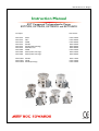
Instruction Manual
EXT Compound Turbomolecular Pumps
EXT75DX, EXT75iDX, EXT255DX and EXT255iDX
Description
EXT75DX
EXT75DX
EXT75DX
EXT75DX
EXT75DX
EXT75DX
EXT75iDX
EXT75iDX
EXT75iDX
Item Number
ISO63
CF63
NW40
ISO100
ISO100 (NW25 Backing)
ISO63 Reversed
NW40
ISO63 (NW16 Interstage)
ISO63 (NW25 Interstage)
EXT255DX ISO100
EXT255DX CF100
EXT255iDX ISO100 (Interstage)
B722-41-000
B722-42-000
B722-43-000
B722-45-000
B722-46-000
B722-48-000
B722-35-000
B722-37-000
B722-38-000
B753-11-000
B753-12-000
B753-13-000
98/37/EC
89/336/EEC
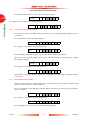
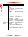
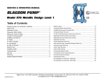
Declaration
of Conformity
We,
BOC Edwards,
ManorRoyal,
Crawley,
WestSussexRH102LW UK
declareunderour soleresponsibility
thatthe machine(s)
EXTTSiDXNW40 (interstage)
EXTT5iDXlSO63/NW1
6 (interstaSe)
EXTTSiDX
lSO63/NW25
(interstage)
EXTTsDXI5063
EXTTsDXCF63
EXTT5DXNW4O
EXTTsDXtSO100
EXTTSDXrSO100(NW2s B-PT)
EXTT5DXlSO63Reversed
8722-35-000
-000
8722-37
8722-38-000
8722-41-000
s722-42-000
8722-43-000
8722-45-QQo
8722-46-000
8722-48-0W
to which this declaration relates is in conformity with the following standard(s)
or other normative document(s)
EN(|SO)12100-2;2003 Safetyof Machinery:BasicConcepts, General Principlesfor Design.
TechnicalPrincioles.
VacuumPumps.
EN 1012-2:1997
SafetyRequirements,
EN61010-1:2001
SafetyRequirements
for ElectricalEquipmentfor Measurement,
Control and Laboratory Use.*
EN61326:1997
Electricalequipmentfor measurement,
control and laboratoryuse (lndustriallocation, EMCrequirements.
ClassB emissions)
*
The pumpscomplywith EN61010-1:2001when installedin accordancewith the
instructionmanualsupplied.
followingthe provisionsof
73l023lEEC
89/336/EEC
98l37lEC
Low Voltage Directive
Electromagnetic
CompatibilityDirective
MachinerySafetyDirective
Bursess
Hill
L 6-6<'{bA
8. D. Brewster,TechnicolMonoger
BurgessHill Products
Ihrs
.W
hds beet
Doteand Place
undero
BOC EDWARDS
to lSO900l
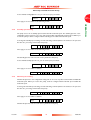
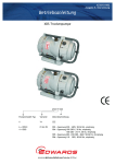
Declarationof Conformity
Wq
BOC Edwards,
Manor Royal,
Crawley,
West Sussex RH10 2LW UK
declareunder our sole responsibilitythat the machine(s)
EXT255DXtSO100
EXr255DX CF100
EXTZ55iDXlSOl00(lnterstage)
B753-11-0m
8753-12-000
8753-13-000
to which this declarationrelatesis in conformitywith the followingstahdard(s)
or other normativedocument(s)
EN(SO)12100-2 2003 Safetyof Machinery:BasicConcepts,GeneralPrinciplesfor Design.
TechnicalPrinciples.
EN '1012-2:1997
SafelyRequirements,
VacuumPumps.
EN6101O1:2001
SafetyRequirementsfor ElectricalEquipmentfor Measuremen!,
Control and LaboratoryUse.*
EN61326:1997
Elecfiicalequipmentfor measuremenqcontrol and laboratoryuse (lndustrlallocation,
EMCrequirements.
ClassB emissions)
*
The pumpscomplywith EN6'10'10-1:
2001 when installedin accordancewith the
instruction manualsupplied.
followingthe provisionsof
73l023lEEC
89/336/EEC
98l37lEC
Low Voltage Directive
Electromagnetic
CompatibilityDireclive
MachinerySafetyDirective
b<-__--,'---\tZ-/-.----'
B.D. Brev/ster,
Technicol
ll,ono+er
Burgess
Hill Products
2-t1-t-^ t-o-?
Dote ond Place
ThE Dtoduct hos been manufoctured undet o qudlitv svstemreeisteredto lSO9001
,W
BOC EDWARDS
?.DOG
Burgess
Hill
;
EXT Compound Turbomolecular Pumps
CONTENTS
Section
Page
INTRODUCTION
Scope and definitions
General description
Drive electronics
Operational features
Power limit setting
Standby speed
Timer
Analogue output
Automatic vent options
Normal speed setting
Electronic braking
Logic interface
Parallel control and monitoring
Full serial control
Serial control with parallel monitoring
Parallel control with occasional serial monitoring or serial set-up
Podule configuration (serial set-up)
2
2.1
2.2
2.3
2.4
2.5
2.6
2.7
2.8
2.9
2.10
2.11
TECHNICAL DATA
General
Pumping media
Vent gas specification and vent control data
Purge gas specification
Cooling water
Materials exposed to gases pumped
Electrical data
Logic interface connector
Podule connector socket
Indicator LEDs
Operating and storage environment
1
1
2
3
3
3
4
4
4
5
5
5
6
6
6
7
7
7
9
9
9
16
17
17
17
17
18
20
21
21
djd 0293
1
1.1
1.2
1.3
1.4
1.4.1
1.4.2
1.4.3
1.4.4
1.4.5
1.4.6
1.4.7
1.5
1.5.1
1.5.2
1.5.3
1.5.4
1.5.5
Issue D
i
20.06.06
PAGE
i
EXT Compound Turbomolecular Pumps
CONTENTS (CONTINUED)
PAGE
ii
3
3.1
3.2
3.3
3.3.1
3.3.2
3.3.3
3.3.4
3.3.5
3.3.6
3.4
3.4.1
3.4.2
3.5
3.5.1
3.5.2
3.5.3
3.5.4
3.5.5
3.6
3.7
3.7.1
3.7.2
3.7.3
3.7.4
3.7.5
3.7.6
3.7.7
3.8
3.8.1
3.8.2
3.8.3
3.8.4
3.9
3.9.1
3.9.2
3.9.3
Issue D
INSTALLATION
Unpack and inspect
Typical installation
Connection to the vacuum system
Inlet-screen (supplied fitted)
Mechanical fixing
Inlet-connection and orientation
Base Mounting
Backing connection
Interstage connection (iDX variants only)
Purge gas connection
Connect the purge gas
Recommended purge gas flow
Electrical installation
Introduction
Earth (ground) connections
Connect the logic interface to the TIC
Connect the logic interface to your control equipment
Connect the electrical supply
Parallel interface mode
Serial interface mode
Connect the serial interface to your control equipment
Serial enable
Serial protocol
Message structure
Command set
Simultaneous parallel and serial operation
Multi-drop mode
Vent options, vent valve connection and control
Manual vent valve
TAV5 or TAV6 solenoid vent valve
Controlled venting
Alternative valve connected to the vacuum system
Cooling
Introduction
Forced air cooling
Water-cooling
ii
23
23
23
23
25
26
26
26
27
27
27
27
28
28
28
28
28
28
29
30
31
31
32
32
33
34
34
37
38
38
38
39
40
40
40
40
41
20.06.06
EXT Compound Turbomolecular Pumps
CONTENTS (CONTINUED)
4
4.1
4.1.1
4.1.2
4.1.3
4.1.4
4.1.5
4.1.6
4.1.7
4.1.8
4.1.9
4.1.10
4.2
4.3
4.3.1
4.3.2
4.4
4.4.1
4.4.2
4.4.3
4.4.4
4.5
4.5.1
4.5.2
4.5.3
4.5.4
4.5.5
4.5.6
4.5.7
4.6
4.7
4.8
4.9
4.9.1
4.9.2
4.9.3
4.9.4
4.10
OPERATION
Configuring the DX pump using Serial Commands
Power limit setting
Powering a fan from the Podule
Controlled venting options
Standby speed setting
Normal speed setting
Timer setting and options
Analogue signal options
Electronic braking options
Factory settings
Assigning a multi-drop address
Configuring the DX Pump using a TIC
Start-up
Close the vent valve
Pre-start checks
Operation with Parallel Control and Monitoring
Start the pump
Running at standby speed
Stop the pump
Parallel monitoring
Operation with Serial Control and Monitoring
Delayed start
Start the pump
Standby Speed
Stop the pump
Temperature readings
Link parameter readings
Measured motor speed
Simultaneous Parallel and Serial Operation
Operation with a TIC
Decelerating and venting
Operation at extreme conditions
Operation with high inlet pressure
Operation at high temperatures
Operation at over-speed
Electrical supply failure
Bakeout
43
43
43
44
44
45
45
46
47
48
48
49
50
50
50
51
51
51
51
51
51
52
52
52
52
53
53
53
53
54
54
54
54
54
55
55
55
56
5
5.1
5.2
5.3
5.4
5.5
5.5.1
5.5.2
5.5.3
MAINTENANCE
Introduction
Bearing maintenance
Rotor life
Clean the external surfaces of the pump
Fault finding
Flashing error codes
Decoding system status words
Useful service information
59
59
59
59
59
60
62
63
65
6
6.1
6.2
STORAGE AND DISPOSAL
Storage
Disposal
67
67
67
Issue D
iii
20.06.06
PAGE
iii
EXT Compound Turbomolecular Pumps
CONTENTS (CONTINUED)
PAGE
iv
7
7.1
7.2
7.2.1
7.3
7.3.1
7.3.2
7.3.3
7.4
7.4.1
7.4.2
7.4.3
7.4.4
7.4.5
7.4.6
7.4.7
7.4.8
7.4.9
7.4.10
7.4.11
7.4.12
SERVICE, SPARES AND ACCESSORIES
Introduction
Service
Returning a pump for service
Spares
ISX inlet-screen
Inlet-strainer
Inlet-flange seals
Accessories
Installation
ACX air-cooler
WCX water-cooler
BX bakeout band
TAV vent-valve and vent-port adaptor
VRX vent-restrictor
Vent-port adaptor
PRX purge-restrictor
Vibration isolators
FL20K foreline trap
Podule connector plug
TIC PC Program
69
69
69
69
70
70
70
70
70
70
70
71
71
71
71
72
72
72
72
73
73
ILLUSTRATIONS
Figure
1
2
3
4
5
6
7
8
9
10
11
12
Issue D
Page
EXT75DX dimensions (mm)
EXT255DX dimensions (mm)
Maximum allowed rate of pressure rise during venting: pressure against time
(with pump initially at full rotational speed)
Podule connector plug
Typical pumping system with a DX pump
Correct installation of the inlet-screen (EXT75DX)
Correct installation of the inlet-screen (EXT255DX)
Logic interface connections - parallel mode
Logic interface connections - serial mode
Conceptual diagram for multi-drop connection
Schematic diagram of the logic interface connections
Installation of optional accessories and spares
iv
14
15
16
20
24
25
25
30
32
33
37
74
20.06.06
EXT Compound Turbomolecular Pumps
TABLES
Table
1
2
3
4
5
6
7
8
9
10
11
12
13
14
15
16
17
18
19
20
21
22
23
24
25
26
27
Issue D
Page
Power limits
3
General data
9
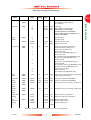
DX pumps technical data
11
Vent gas specification and vent control
16
Purge gas specification
17
Cooling water specification
17
Logic interface technical data
19
Logic interface connector pins
20
Podule technical data
21
Indicator LEDs
21
Operating and storage environment
21
Checklist of components
23
Summary of commands that can be sent to the DX pump
35
Command abbreviations
36
Error codes
36
Vent options
39
Vent-restrictor orifice diameter (with atmospheric pressure at the inlet of the vent-valve) 40
Power limit setting
43
Analogue signal options
47
Behaviour of a pump when the power is re-instated after an electrical supply failure
57
Fault finding
60
Flashing error codes
62
Hexadecimal conversion table
63
Status flags
64
Example decoding of system status words
65
Inlet-flange seals
70
Vent-restrictors
71
v
20.06.06
PAGE
v
EXT Compound Turbomolecular Pumps
PAGE
vi
This page intentionally blank.
Issue D
vi
20.06.06
EXT Compound Turbomolecular Pumps
1
INTRODUCTION
1.1
Scope and definitions
PAGE
1
Read this manual before you install and operate the DX pump. Important safety information is highlighted
as WARNING and CAUTION instructions; you must obey these instructions. The use of WARNINGS
and CAUTIONS is defined below.
WARNING
Warnings are given where failure to observe the instruction could result in injury or death
to people.
CAUTION
Cautions are given where failure to observe the instruction could result in damage to the equipment,
associated equipment and process.
The units used throughout this manual conform to the SI international system of units of measurement.
When flow rates are specified, the abbreviation ‘sccm’ is used to mean standard cubic centimetres per
minute. This is a flow of 1 cm3 min-1 at an ambient temperature of 0ºC and a pressure of 1013 mbar
(1.013 x 10⁵ Pa).
In accordance with standard EN61010, the following warning label appears on the DX pump:
Warning – refer to accompanying documentation.
Warning – hot surfaces.
The units used throughout this manual conform to the SI international system of units of measurement;
where appropriate US equivalent units of measurement are also given.
Issue D
1
20.06.06
INTRODUCTION
This manual provides installation, operation, maintenance and storage instructions for the BOC Edwards
DX Compound Turbomolecular Pumps. You must use the DX pumps as specified in this manual. If you
do not, the protection provided by the DX pumps may be impaired.
EXT Compound Turbomolecular Pumps
1.2
General description
PAGE
2
WARNING
INTRODUCTION
Improper use of the equipment could cause damage to it or injury to people. The user is
responsible for the safe operation, installation and monitoring of the system.
WARNING
The Podule contains electrolytic capacitors and, under certain fault conditions, may emit
dangerous fumes. Ensure that the Podule is operated in a well-ventilated area.
CAUTION
Do not attempt to separate the Podule from the pump since this will cause damage to the electrical
connections.
The DX pumps consist of the compound turbomolecular pump with a permanently attached Podule
containing drive electronics.
The Podule controls the electrical supply to the pump. It has no manual controls and can only be
operated through the logic interface. To operate the DX pump you must connect it to your own control
equipment and power supply or alternatively use the BOC Edwards TIC Turbo Instrument Controller
or TIC Turbo Controller.
The Podule drives the brush-less d.c. motor in the pump. The pump has three Hall effect devices that
operate as rotor position sensors and ensure that the drive current is correctly commutated around the
motor phase-windings.
The vacuum pump contains turbomolecular blades and a Holweck drag mechanism on a single shaft; the
Holweck mechanism allows operation at higher backing pressures than pure turbomolecular pumps.
DX pumps are supplied with an inlet-screen fitted into the bore of the inlet-flange. Both the EXT255iDX
and the EXT75iDX with an NW25 interstage port are supplied with an inlet-strainer that fits into the
interstage-port. The inlet-screen and inlet-strainer protect the pump against damage that would be
caused by debris entering the pump. The inlet-screen also protects the user against injury from the sharp
blades in the pump.
Note: The EXT75iDX with an NW16 interstage port is not supplied with an inlet-strainer.
The DX pumps have a vent-port for venting the pump and vacuum system to atmospheric pressure. The
pump is supplied with a manual vent-valve fitted; this can be replaced with a TAV5 or TAV6 solenoidoperated vent-valve (available as accessories – see Section 7).
The DX pumps have a purge-port: an inert purge gas can be introduced to protect the bearing and motor
from corrosion, or the bearing lubricant from oxidisation. An optional vent-port adapter and purge
restrictor can be fitted to the purge-port to control the flow rate of the purge gas and to filter the gas
supply. (Refer to Section 7).
Air-coolers and a water-cooling block are available as optional accessories to cool the DX pumps. (Refer
to Section 7).
Issue D
2
20.06.06
EXT Compound Turbomolecular Pumps
1.3
Drive electronics
The Podule contains the drive electronics that control the pump operation and accessories such as a TAV
vent valve or air cooler. There is a connector socket on the top of the Podule where the TAV vent valve
or air cooler can be plugged-in. (Refer to Section 2.9)
The drive electronics system has a number of built-in safety features to protect the DX pumps from
damage in the event of sustained high pressure or temperature:
1.4
•
The electronics constantly monitor the temperature inside the Podule and the temperature of the
motor within the pump. If either part becomes too hot, the electronics reduce the power supplied
to the pump motor and the pump speed will drop. If the pump rotational speed falls below 50% full
speed, the electronics may trip into Fail condition, depending on how you have configured the
system. (Refer to Section 1.4.3).
•
If the DX pump's inlet pressure increases, the power supplied to the pump-motor increases to
counteract the gas frictional load. However, when the built-in maximum power limit is reached, the
speed of the pump will start to drop. If the pump rotational speed falls below 50% full speed, the
electronics may trip into Fail condition, depending on how you have configured the system. (Refer
to Section 1.4.3).
•
In the event of an electrical supply failure, the drive electronics uses the motor within the pump as
a generator. This means the DX pumps have their own regenerative supply and do not require a
separate battery for emergency power back-up. The regenerated energy is used to maintain the
electrical supply to the connector socket on the Podule until the pump speed falls to below 50% of
full rotational speed: this will ensure that the vent valve remains shut until below 50% of full
rotational speed and will prevent the pump from venting at full speed, provided that there is not
too much loading on the 24 V supply to the pump.
Operational features
In addition to the basic start and stop commands, the DX pumps have several other features for
improved functionality. This allows you to tailor the pump operation to your particular application. Refer
to Table 13 for factory default settings of the parameters discussed in the following Sections.
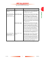
1.4.1
Power limit setting
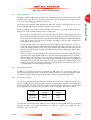
You can select the maximum power that will be drawn by the pump (refer to Section 4.1.1). The more
power you supply, the quicker the pump will accelerate to reach full speed. Therefore if your application
requires fast cycling, you should set the power limit to the maximum value. If ramp time is not important
in your application, you can use a lower power limit, down to a minimum value, refer to Table 1.
Pump
Maximum value
setting
Minimum value
setting
EXT75DX
120 W
50 W
EXT255DX
200 W
80 W
Table 1 – Power limits
You must make sure that the power supply you use is capable of delivering sufficient power to the DX
pump. By choosing a lower power limit setting, you could use a smaller power supply. For more
information, refer to Section 2.7.
Issue D
3
20.06.06
INTRODUCTION
The Podule has two indicator LEDs that signal the status and operation of the pump, that can also be
used for fault-finding if a problem should occur. (Refer to Section 2.10)
PAGE
3
EXT Compound Turbomolecular Pumps
1.4.2
PAGE
4
Standby speed
In Standby mode the pump rotational speed is lower than the full rotational speed.
INTRODUCTION
If your application does not require the pump to be running at maximum speed at all times, you can use
the Standby speed feature rather than switching the pump off. This can save you time since you do not
have to stop or vent the pump and you do not have to wait as long for the pump to accelerate back to
full speed.
The Standby speed is a user-selectable value (refer to Section 4.1.4).
1.4.3
Timer
When the pump is started, an internal timer is automatically started within the drive electronics. If the
pump fails to reach 50% of full rotational speed within the timeout period, the Podule will signal a Fail
and will decelerate the pump to rest. This is a safety feature and prevents the Podule driving the pump
at maximum power for a long time, which could cause damage. The pump may fail to reach 50% speed if
the gas load is too high (for example if there is a leak in the system), if the backing pump fails, or if the
pump is too hot.
The timeout period is a user-selectable feature (refer to Section 4.1.6), so if your application requires the
pump to ramp up slowly, you can extend the timeout period. The Timer is permanently enabled for
ramp-up.
The Timer has an additional function: if the pump rotational speed drops below 50% full speed for any
reason, you may wish to allow the pump time to recover rather than trigger a Fail condition. The Timer
starts as soon as the speed drops to below 50% full speed. If, during the timeout period, the pump
recovers to above 50% full speed then the Timer will be reset. If the pump rotational speed fails to
recover by the end of the timeout period, the Podule will trigger a Fail condition and will decelerate the
pump to rest. When you receive the pump, the Timer function will be enabled, however you can disable
it if you wish to. With the Timer disabled, the pump will Fail and decelerate to rest as soon as pump
rotational speed falls below 50%.
1.4.4
Analogue output
The Podule produces an analogue output that allows you to monitor four different system parameters:
•
Measured pump rotational speed
•
Measured motor power
•
Measured motor temperature
•
Measured controller temperature
The analogue output signal ranges from 0 to 10 V and is directly proportional to the system parameter
(refer to Section 2.8).
Connect the analogue output to a suitable meter or indicator to display the appropriate system
parameter or connect to your control equipment (for example, to operate other components in the
pumping system at preset values).
You can only monitor one system parameter at a time using the analogue output. However, it is easy to
configure the Podule to monitor a different system parameter (refer to Section 4.1.7).
Issue D
4
20.06.06
EXT Compound Turbomolecular Pumps
1.4.5
Automatic vent options
A BOC Edwards TAV vent valve can be connected directly to the DX pump’s Podule. The Podule is
capable of controlling a number of different venting options.
There are many venting options available to you, such as:
•
Hard vent when rotational speed drops below 50%
•
Controlled vent when above 50% speed and hard vent below 50% speed
•
Hard vent immediately through a suitable restrictor
A full list of the venting options is given in Section 3.8.
In addition there is a feature that allows a delayed start of the DX pump. With this feature you can close
the vent valve before you start the DX pump. This allows the backing pump to reduce the pressure in
the vacuum system before starting the DX pump.
If you do not wish to use the Podule to control a TAV vent valve, you could use it to run a fan instead.
You can configure the Podule so that the fan is permanently enabled.
1.4.6
Normal speed setting
The Normal Speed is a user-selectable parameter that can be set anywhere from 50% to 100% of full
rotational speed. When the pump reaches Normal Speed, a signal is available on the Normal pin of the
logic interface connector. You can use this signal to control your application since it shows that pump
speed, and therefore vacuum performance, has reached a minimum specific level. The default setting is
80% of full rotational speed. Refer to Section 4.1.5 for instructions on altering the Normal Speed setting.
1.4.7
Electronic braking
The pump has a user selectable Electronic Braking option, which is disabled by default. With this option
disabled the pump will draw power from the supply when accelerating and running and will coast down
when decelerating.
The Electronic Braking function may be enabled to reduce the pump deceleration time and to recover
some energy from the pump. This is achieved by returning power from the pump to the electrical supply.
The rate at which electrical energy is returned to the supply is regulated so as to limit the supply voltage
to 24 V +10%. In order to achieve the fastest electronic braking times there must be somewhere for the
returned power to go such as:
Issue D
•
a supply capable of receiving the returned power
•
other devices sharing the 24 V bus with the pump
•
a load resistor of approximately 10 Ω switched across the 24 V supply when decelerating the pump
5
20.06.06
INTRODUCTION
The drive electronics can control the rate of venting. Using this feature the pump can be vented from full
rotational speed in a controlled manner that will not damage the pump bearings. Once the pump
rotational speed has dropped to below 50% of maximum speed, it is safe to hard vent (open the vent
valve fully.)
PAGE
5
EXT Compound Turbomolecular Pumps
1.5
PAGE
6
Logic interface
The Podule can only be operated through the logic interface. The signals on the logic interface are of
three types:
INTRODUCTION
•
Control inputs: these are switch-type signals that are used to control the pump
•
Status outputs: these outputs identify the status of the system
•
Analogue output: this provides a 0 – 10V output for a number of pump parameters.
The logic interface has been designed to include both serial and parallel modes of control and monitoring,
operating through one connector. The pump can be operated using either serial or parallel method or
some combination of the two.
The logic interface can be plugged directly into the BOC Edwards TIC Turbo Controller or TIC Turbo
Instrument Controller and then use the functionality that they provide. Alternatively, the logic interface
can be connected to a customers own control system. The most useful arrangements are described in
the sections below.
For more information about the logic interface, refer to Section 2.8.
1.5.1
Parallel control and monitoring
The simple parallel interface is a quick and easy way to control the pump; this is the same interface used
on existing 24V BOC Edwards Turbo Pumps. The controls that are available to use are Start and Standby.
You can monitor the system status using the Normal, Fail and Analogue output signals.
Note: The Serial Enable switch MUST be open (no connection).
Refer to Section 3.6 for more detailed instructions of how to use the parallel interface.
A system operating in pure parallel mode has no facility to adjust the configuration settings stored in the
Podule (for example, power limit setting or controlled venting options). This would place a restriction
in that all these features would be at their factory default settings. However, the Podule could be
configured separately before fitting the DX pump to the system. This is covered in more detail in Section
1.5.5.
1.5.2
Full serial control
The serial communications link provides complete control and monitoring using just three signal lines.
The Serial data RX and TX use the same connector pins as the parallel signals Standby and Fail
respectively.
The Serial Enable signal MUST be linked to 0V for the system to accept commands in Serial control mode.
This is a safety feature and acts as an interlock. In addition, the parallel Start signal must be left
unconnected for Serial commands to be accepted in full Serial control mode.
The Podule will still provide the Normal and Analogue signals on the logic interface connector even when
operating in full Serial control mode. The status of the Normal signal can also be obtained by
interrogating the system status via the Serial interface.
For more information about the Serial interface, refer to Section 3.7.
Issue D
6
20.06.06
EXT Compound Turbomolecular Pumps
1.5.3
Serial control with parallel monitoring
Since Normal and Analogue signals remain available even using Serial control mode, it is possible to
control the pump via the Serial interface whilst monitoring these signals using a parallel link.
1.5.4
Parallel control with occasional serial monitoring or serial set-up
This method of control is best for users who normally wish to operate the pump in parallel mode but
occasionally want to adjust the configuration settings stored in the Podule or to monitor operational
status of the pump.
Whilst operating in Parallel mode, the same controls and monitoring signals are available as described in
Section 1.5.1. It must be remembered that the Serial data RX shares the same connector pin as the
Standby signal so the pump cannot be commanded into Standby speed using this line.
The Serial Enable signal must be linked to 0V for serial communications to take place. We suggest that
you make a special cable for serial communications that includes a link between Serial Enable and 0V.
This way, Serial Enable is automatically activated when the cable is connected and then deactivated when
the cable is removed.
1.5.5
Podule configuration (serial set-up)
All the configuration settings stored within the Podule are retained even when power to the DX pump
is removed. This means that it is possible to use a separate system to configure the Podule before fitting
the DX pump to your application. This gives the benefit of tailoring the pump functionality to a customer
application and allows the pump to be operated using a simple parallel interface system.
To configure the DX pump, either use your own simple serial system or use the BOC Edwards TIC
Turbo Controller or Turbo Instrument Controller. The TICs have a feature which allows storage of a
DX pump’s configuration. The configuration can then be downloaded to another DX pump. This is
useful when configuring a number of DX pumps with the same settings before they are fitted to a system.
The TIC is supplied with a WindowsTM based PC program which allows the DX pump to be configured
from a single PC. The program has a simple user interface which means that it is not necessary to use
the ASCII message protocol described in section 3.7. The TIC PC Program has a facility to save multiple
DX pump configurations which can then be downloaded into other DX pumps.
Issue D
7
20.06.06
INTRODUCTION
Again, the Serial data RX and TX use the same connector pins as the parallel signals Standby and Fail
respectively so these parallel control and monitoring signals are not available. The Serial Enable signal
MUST be linked to 0V and the Start switch must remain open (no connection).
PAGE
7
EXT Compound Turbomolecular Pumps
PAGE
8
INTRODUCTION
This page intentionally blank.
Issue D
8
20.06.06
EXT Compound Turbomolecular Pumps
2
TECHNICAL DATA
2.1
General
PAGE
9
Reference data
Performance
Refer to Table 3
Dimensions
Refer to Figures 1 and 2
TECHNICAL DATA
General items
Maximum inlet-flange temperature
ISO63 / ISO100 / NW40
70 oC with cooling water
DN63CF (EXT75DX) / DN100CF (EXT255DX)
100 oC bakeout, with cooling water
Maximum permitted external magnetic field
EXT255DX
3.5mT horizontal field, 7mT vertical field
EXT75DX
5mT
Pollution degree
EN61010, category 2
Equipment type
Fixed equipment, for indoor use only
Enclosure protection (installed)
EXT255DX & 255iDX
IP50
EXT75DX & 75iDX/NW25
IP50
EXT75iDX/NW16
IP50
Table 2 – General data
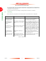
2.2
Pumping media
WARNING
Vent dangerous gases and gas mixtures safely, do not expose people to these gases. If
pumping hazardous gases or vapours, observe the safety recommendations of the
supplier of the gas/vapour.
WARNING
Do not use the DX pump to pump pyrophoric or explosive gas mixtures, as it is not
suitable for this purpose. The pump and its connections are not designed to contain an
explosion.
WARNING
In the interstage versions of the DX pumps, gas pumped through the interstage port will
mix with gas pumped through the pump inlet. Ensure that the gases will not react or
combine to form dangerous gases and substances.
WARNING
Do not expose any part of the human body to vacuum.
Issue D
9
20.06.06
EXT Compound Turbomolecular Pumps
CAUTION
PAGE
10
Do not use the DX pump to pump gases containing more than 20% oxygen unless the pump is gas
purged. If you do, the lubricant will polymerise and the pump may fail prematurely.
TECHNICAL DATA
CAUTION
Do not use a DX pump to pump mercury vapour and do not allow mercury (for example, from a
McLeod gauge) to come into contact with the pump. If you do, the pump rotor may corrode and fail.
Note: Concentrations of gases may be modified by the compression of the pump.
The pumps are designed to pump the following residual gases normally used in high-vacuum systems:
• Air
• Carbon dioxide
• Methane
• Neon
• Propane
• Krypton
• Butane
• Helium
• Carbon monoxide
• Ethane
• Nitrogen
• Argon
• Hydrogen
You can use the pump to pump oxygen and water vapour, subject to the following conditions:
•
Oxygen – when the pump is purged by an inert gas, oxygen can be pumped at concentrations above
20% by volume. Refer to Section 2.4 for Purge gas specification. However, if the pump is not
purged, the oxygen concentration must be less than 20% by volume.
•
Water vapour - you must ensure that vapour does not condense inside the pump; refer to
Section 3.9.3.
If you wish to pump a gas not in the list above, contact your supplier for advice. If you do not contact
your supplier, you may invalidate the warranty on the pump. The pump is not suitable for pumping
aggressive or corrosive gases.
Issue D
10
20.06.06
EXT Compound Turbomolecular Pumps
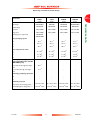
EXT75DX
63CF
EXT75DX
NW40
EXT75DX
ISO100
3.0 kg
4.9 kg
2.9 kg
3.2 kg
DN63ISO-K
DN63CF
DN40NW
DN100ISO-K
DN16NW
DN16NW
DN16NW
DN16NW
Vent-port
1/8 inch BSP
1/8 inch BSP
1/8 inch BSP
1/8 inch BSP
Purge-port
1/8 inch BSP
1/8 inch BSP
1/8 inch BSP
1/8 inch BSP
Interstage-port (optional)
DN25NW
& DN16NW
-
-
-
N2
61 l s-1
61 l s-1
42 l s-1
66 l s-1
He
57 l s -1
57 l s-1
49 l s-1
59 l s-1
H2
53 l s-1
53 l s-1
48 l s-1
54 l s-1
N2
>1 x 10¹¹
>1 x 10¹¹
>1 x 10¹¹
>1 x 10¹¹
He
1 x 10⁶
1 x 10⁶
1 x 10⁶
1 x 10⁶
H2
5 x 10⁴
5 x 10⁴
5 x 10⁴
5 x 10⁴
70 sccm flow through interstageport
10 l s-1
-
-
-
5 sccm flow through interstageport
3 l s-1
-
-
-
Mass
Inlet-flange
Outlet-flange
Inlet pumping speed
Inlet compression ratio
Interstage pumping speed, for
interstage DX pumps with N2
(DN16NW port)
-
Interstage pumping speed, for
N2
-
-
-
-
He
-
-
-
-
10-9
10-10
10-9
-
Ultimate pressure:
mbar
with rotary vane backing pump: *
<5 x
with diaphragm backing pump: ++
<5 x 10⁻⁸ mbar
<5 x
mbar
<5 x 10⁻⁹ mbar
mbar
<5 x 10⁻⁹ mbar
<5 x 10⁻⁸ mbar
<5 x 10⁻⁸ mbar
<5 x
Table 3 – DX pumps technical data
Issue D
11
20.06.06
PAGE
11
TECHNICAL DATA
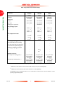
EXT75DX
ISO63
Parameter
EXT Compound Turbomolecular Pumps
PAGE
12
EXT255DX
ISO100
EXT255iDX
ISO100
EXT255DX
100CF
6.25 kg
6.5 kg
8.5 kg
DN100ISO-K
DN100ISO-K
DN100CF
DN25NW
DN25NW
DN25NW
Vent-port
1/8 inch BSP
1/8 inch BSP
1/8 inch BSP
Purge-port
1/8 inch BSP
1/8 inch BSP
1/8 inch BSP
-
DN25NW
-
N2
220 l s-1 ‡
220 l s-1 ‡
220 l s-1 ‡
He
230 l s-1 ‡
230 l s-1 ‡
230 l s-1 ‡
H2
180 l s-1 ‡
180 l s-1 ‡
180 l s-1 ‡
N2
>1 x 10⁸
>1 x 10⁸
>1 x 10⁸
He
4 x 10⁵
3 x 10⁵
4 x 10⁵
H2
1 x 10⁴
1 x 10⁴
1 x 10⁴
70 sccm flow through interstage-port
-
-
-
5 sccm flow through interstage-port
-
-
-
N2
-
10 l s-1
-
He
-
8 l s-1
-
<5 x 10⁻⁹ mbar
(DN100ISO-K
inlet-flange)
<5 x 10⁻⁸ mbar
(DN100ISO-K
inlet-flange)
<5 x 10⁻⁹ mbar
(DN100ISO-K
inlet-flange)
<5 x 10⁻⁸ mbar
(DN100ISO-K
inlet-flange)
<5 x 10⁻¹⁰ mbar
(DN100CF
inlet-flange)
<5 x 10⁻⁹ mbar
(DN100CF
inlet-flange)
Parameter
Mass
TECHNICAL DATA
Inlet-flange
Outlet-flange
Interstage-port (optional)
Inlet pumping speed
Inlet compression ratio
Interstage pumping speed, for
interstage DX pumps with N2
Interstage pumping speed, for
Ultimate pressure:
with rotary vane backing pump: *
with diaphragm backing pump: ++
Table 3 - DX pumps technical data (continued)
* Ultimate pressure 48 hours after bakeout with 2-stage rotary vane backing-pump.
++
Ultimate pressure 48 hours after bakeout with Pb < 5 mbar (500 Pa).
‡ Pumping speeds are without inlet-screen or inlet-strainer. Inlet-screens and inlet-strainers reduce
speed by approximately 10%.
Issue D
12
20.06.06
EXT Compound Turbomolecular Pumps
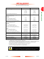
Parameter
EXT75DX
Critical backing pressure
EXT255DX
PAGE
13
†
8 mbar
12 mbar
He
H2
6.5 mbar
2.5 mbar
9 mbar
2.5 mbar
Minimum backing pump displacement
0.6 m3 h-1
0.6 m3 h-1
4 mbar
7 mbar
5 mbar
2 mbar
5 mbar
2 mbar
TECHNICAL DATA
N2
Maximum Continuous Backing Pressure*
(at Ultimate Inlet Pressure)
Nitrogen:
Water Cooling (40°C ambient)‡
Forced Air Cooling (35°C ambient
Natural Convection Cooling (30°C ambient)
Maximum continuous inlet pressure*
(at Ultimate Backing Pressure)
Nitrogen:
Water cooling (40ºC ambient)‡
Forced Air cooling at (35ºC ambient)
2 x 10⁻² mbar
1 x 10⁻² mbar
3 x 10⁻² mbar
8 x 10⁻³ mbar
Natural Convection Cooling (30°C ambient)
8 x 10⁻³ mbar
2 x 10⁻³ mbar
4 x 10⁻³ mbar
7 x 10⁻³ mbar
4 x 10⁻³ mbar
5 x 10⁻³ mbar
Argon:
Water cooling (40ºC ambient)‡
Forced Air cooling at (35ºC ambient)
Natural Convection Cooling (30°C ambient)
Recommended backing pump¹
Operating attitude
Nominal rotational speed
Starting time to 90% speed²
Sound power level (1 metre away)
1 x 10⁻³ mbar
1 x 10⁻³ mbar
RV3
RV12
Vertical and upright through Vertical and upright through
to horizontal ± 2 °
to horizontal ± 2 °
90,000 revolutions per
60,000 revolutions per
minute
minute
110 seconds
78 seconds
< 50 dB(A)
<50 dB(A)
Table 3 - DX pumps technical data (continued)
Pumping speed is reduced to 90% of its original value.
* Above this pressure, rotational speed drops below nominal. Values for maximum continuous inlet
pressure obtained using a RV12 backing pump. Refer to Section 3.9 for cooling conditions.
‡ Cooling water temperature at 15°C. Cooling water flow rate at 30 l hr-1.
¹ A suitable diaphram pump with ultimate <5 mbar may also be used.
² Power limit setting 80 W (EXT75DX), 160 W (EXT255DX).
†
WARNING
Do not exceed the maximum continuous operating pressure. Doing so can result in
dangerous rotor temperatures and will shorten the life of the pump.
Issue D
13
20.06.06
EXT Compound Turbomolecular Pumps
PAGE
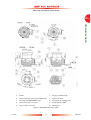
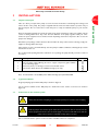
14
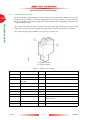
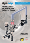
TECHNICAL DATA
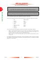
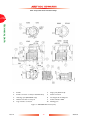
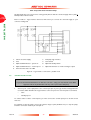
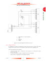
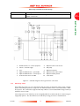
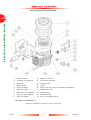
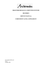
1.
Podule
6.
Purge port (blanked off)
2.
Podule connector socket (for fan/TAV valve)
7.
Earth connection
3.
Interstage port (EXT75iDX only)
8.
Cooling block mounting face
4.
Manual vent valve in vent port
9.
Podule indicator LEDs
5.
Logic interface connector
10.
Backing port
Figure 1 – EXT75DX dimensions (mm)
Issue D
14
20.06.06
EXT Compound Turbomolecular Pumps
PAGE
15
TECHNICAL DATA
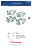
1.
Podule
6.
Purge port (blanked off)
2.
Podule connector socket (for fan/TAV valve)
7.
Earth connection
3.
Interstage port (EXT255iDX only)
8.
Cooling block mounting frame
4.
Manual vent valve in vent port
9.
Podule indicator LEDs
5.
Logic interface connector
10.
Backing port
Figure 2 – EXT255DX dimensions (mm)
Issue D
15
20.06.06
EXT Compound Turbomolecular Pumps
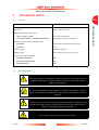
2.3
PAGE
16
Vent gas specification and vent control data
TECHNICAL DATA
Although the pump may be vented to atmosphere, high relative humidity of the air may greatly increase
the subsequent pump-down time. To reduce pump-down times you should vent with dry, clean gases.
Refer to Section 3.8 for a description of the vent options and the vent valve connection and refer to
Section 4.1.3 for configuring the venting options.
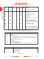
Vent gas specification and control
Reference data
Vent gas
Dry air, nitrogen, argon or other inert gases
Maximum dew point at atmospheric pressure
-22 oC
Maximum size of particulates
1 μm
Maximum concentration of oil
0.1 parts per million
Recommended time for rotational speed to
reach 50%
> 15 seconds
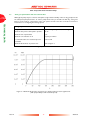
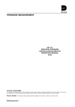
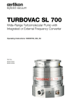
Maximum allowed rate of pressure rise
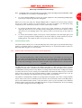
Refer to Figure 3
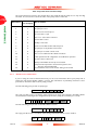
Table 4 – Vent gas specification and vent control
Figure 3 – Maximum allowed rate of pressure rise during venting: pressure against time
(with pump initially at full rotational speed)
Issue D
16
20.06.06
EXT Compound Turbomolecular Pumps
2.4
Purge gas specification
PAGE
17
Reference data
Purge gas
Dry air, nitrogen, argon or other inert gases
Maximum dew point at atmospheric pressure
-22 oC
Maximum size of particulates
1 μm
Maximum concentration of oil
0.1 parts per million
Allowable purge gas flow (when required)
20 to 50 sccm (0.33 to 0.84 mbar l s-1 or 33 to 84 Pa l s-1)
Recommended purge gas flow
25 sccm (0.42 mbar l s-1, 42 Pa l s-1)
Maximum allowable purge gas supply pressure
2 bar (gauge); 29 psi, 3 x 10⁵ Pa
Table 5 – Purge gas specification
Cooling water specification
Reference data
Quality
Mechanically clean and optically clear with no deposits or
turbidity
pH value
6.0 to 8.0
Maximum calcium carbonate concentration
75 parts per million
Maximum chloride concentration
100 parts per million
Minimum oxygen concentration
4 parts per million
Minimum cooling water flow rate (at 15 oC)
15 l hr-1
Water temperature
Refer to Table 3
Maximum water pressure
5 bar (gauge), 73.5 psig, 6 x 10⁵ Pa
Materials exposed to cooling-water
Nickel plated brass
Table 6 – Cooling water specification
2.5
Cooling water
The above cooling water specification corresponds to a typical high-quality drinking water specification.
Check with your water supply authority if you are in doubt about the quality of your supply.
2.6
Materials exposed to gases pumped
The following materials and component types are exposed to the gases pumped:
Aluminium alloys, stainless steels, fluoroelastomer and nitrile O-rings, hydrocarbon lubricant, felt,
rare earth magnets, silicon nitride, phenolic resin, carbon-fibre reinforced epoxy resin, fire
retardant polypropylene, polyamide and PVC.
2.7
Electrical data
DX pumps can be driven either by your own system or by the BOC Edwards TIC Turbo Instrument
Controller or TIC Turbo Controller.
Issue D
17
20.06.06
TECHNICAL DATA
Purge gas specification
EXT Compound Turbomolecular Pumps
If you wish to use your own system, the size of the power supply you must use depends on your
application. The power limit setting determines how quickly you can ramp up the pump and dictates the
size of power supply you will need. If you have serial communications capability, or have access to a
BOC Edwards TIC, you can select the power limit setting of the DX pump. Refer to Table 7 for the
maximum and minimum power limit settings for DX pumps and for the associated maximum input
current requirements. If your application requires rapid cycling of the pump, you can achieve faster ramp
times if you use a power supply that delivers higher current, up to a maximum in accordance with Table 7.
PAGE
18
TECHNICAL DATA
If you do not have the facility to adjust the power limit setting, you must use a power supply capable of
delivering enough current to meet the BOC Edwards factory default power limit setting, shown in
Table 7. For the EXT75DX this would be around 4 amps and for the EXT255DX it would be around
7 amps.
If you intend to drive the DX pump using a BOC Edwards TIC, be aware that there are several variants.
Contact BOC Edwards to determine which is most suitable for your application.
2.8
Logic interface connector
DX pumps have a 15-way logic interface connector on the end of the logic interface cable (see Figures 1
& 2, items 11 and 3 respectively). The logic interface connector can be plugged directly into the BOC
Edwards TIC Turbo Instrument Controller or TIC Turbo Controller. You must use a suitable connector
mating half (not supplied) to connect the DX pump to your own equipment. Refer to Table 7 for the
connector mating half type and to Table 8 for Logic Interface connector pins for the electrical
connections.
Issue D
18
20.06.06
EXT Compound Turbomolecular Pumps
EXT75DX
15-way D-type male
EXT255DX
15-way D-type male
24 V d.c. +5%, -10%
(21.6 to 25.2 V d.c.)
0.5 V r.m.s.
<6 A at 24 V during ramp
24 V d.c. +5%, -10%
(21.6 to 25.2 V d.c.)
0.5 V r.m.s.
<10 A at 24 V during ramp
<3 A at 24 V
<5 A at 24 V
6 A type 'T' IEC approved or
6 A time delay fuse UL/CSA
approved
80 W
120 W
50 W
10 A type 'T' IEC approved or
10 A time delay fuse UL/CSA
approved
160 W
200 W
80 W
Factory default setting
Maximum power limit
Minimum power limit
Hardware control input signal:
Enabled control voltage: low (close) 0 to 0.8 V d.c. (Iout = 0.55 mA
nominal)
Disabled control voltage: high
4 to 26.4 V d.c. (Internal pull up to
(open)
6.35 V nominal)
Analogue output:
Output voltage
0 to 10 V d.c. (directly proportional
to measured parameter)
Motor speed: 0 - 1500 Hz (0-100%)
Motor power: 0 - 120 W
Motor temperature: 0 - 100 oC
Controller temperature: 0 - 100 oC
Output current
< 5 mA
NORMAL status output:
Type
Open collector transistor
< Normal speed (default 80%)
Off (2.2 kΩ pull up to 12 V d.c.)
> Normal speed
On (<0.8 V d.c. sinking 20 mA)
Rating
20 mA to 0 V
FAIL status output:
Type
Open collector transistor
Fail
Off (3.3 kΩ pull up to 12 V d.c.)
OK
On (<0.1 V d.c. sinking 1.7 mA,
<0.8 V d.c. sinking 20 mA)
Rating
20 mA to 0 V
PAGE
19
0 to 0.8 V d.c. (Iout = 0.55 mA
nominal)
4 to 26.4 V d.c. (Internal pull up to
6.35 V nominal)
0 to 10 V d.c. (directly proportional
to measured parameter)
Motor speed: 0 - 1000 Hz (0-100%)
Motor power: 0 - 200 W
Motor temperature: 0 - 100 oC
Controller temperature: 0 - 100 oC
< 5 mA
Open collector transistor
Off (2.2 kΩ pull up to 12 V d.c.)
On (<0.8 V d.c. sinking 20 mA)
20 mA to 0 V
Open collector transistor
Off (3.3 kΩ pull up to 12 V d.c.)
On (<0.1 V d.c. sinking 1.7 mA,
<0.8 V d.c. sinking 20 mA)
20 mA to 0 V
Table 7 – Logic interface technical data
*
Mating half of connector not supplied.
Issue D
19
20.06.06
TECHNICAL DATA
Logic interface item
Connector*
DX pumps electrical supply:
Allowable voltage range
(including any ripple)
Maximum voltage ripple
Maximum input current with
maximum power limit setting
Maximum input current with
minimum power limit setting
Fuse (or equivalent current
limiting device) rating
EXT Compound Turbomolecular Pumps
2.9
Podule connector socket
PAGE
20
TECHNICAL DATA
The DX pump has a 2-way Podule Connector Socket in the top of the Podule. When you receive the
pump, this connector will be concealed by a black protective cover. If you intend to use the connector,
this cover should be removed by levering with a small screwdriver. The mating plug for this connector
is supplied with the pump.
The connector is intended to drive a vent valve or fan connected to the two pins. The connector mating
plug is shown in Figure 4, with the polarity of the pins marked when the vent valve/fan is energised.
The podule connector plug is available as an accessory, see Section 7.4.
1. Negative terminal
2. Positive terminal
Figure 4 – Podule connector plug
Pin Number
Signal
Polarity
Use
2
0 V Control reference
-
0 V reference for all control and status signals
3
START/STOP control input
-
Connect to Pin 2 to start pump
4
STANDBY control input /
Serial RX
-
Connect to Pin 2 to enable standby speed
5
Serial enable
-
Connect to Pin 2 to enable serial interface mode
7
FAIL / Serial TX
-
Logic high when fail condition exists in parallel mode
9
Analogue output
Positive
10
Chassis / Screen
-
Screen
12
Chassis / Screen
-
-
15
NORMAL status output
-
Logic low when pump rotational speed is at normal
speed or above
8, 13, 14
Electrical supply: 0 V
-
1, 6, 11
Electrical supply: 24 V
Positive
0 - 10 V output proportional to measured output
Table 8 – Logic interface connector pins
Issue D
20
20.06.06
EXT Compound Turbomolecular Pumps
Data
Connector plug
Phoenix part number FKMC1881325
Voltage output
24 V d.c. +10%, -20% (19.2 to 26.4 V d.c.)
Current output
120 mA
PAGE
21
Table 9 – Podule technical data
2.10
Indicator LEDs
The DX pump has two indicator LEDs, shown in Figures 1 and 2 as item 8.
LED
Description
Status LED
This yellow LED flashes with a 50% duty cycle at the rotational
frequency of the pump motor. At high speeds it appears continuously
on.
The LED switches off when the rotational speed is very low or
stopped.
In a fail condition this LED flashes in a sequence to indicate error
codes and can be used for fault finding. Refer to Section 5.5.
Normal LED
This green LED remains on all the time that the pump rotational
speed is above the Normal speed setting, irrespective of whether
the pump is accelerating or decelerating.
Table 10 – Indicator LEDs
Note:
If excessive electrical load is applied to the Normal output line, the Normal LED may illuminate.
2.11
Operating and storage environment
Range
Data
Ambient operating temperature range
5 oC to 40 oC
Ambient operating humidity range
10 to 90% RH (non-condensing)
Maximum operating altitude
3000 m
Ambient storage temperature range
-30 oC to 70 oC
Table 11 – Operating and storage environment
Issue D
21
20.06.06
TECHNICAL DATA
Description
EXT Compound Turbomolecular Pumps
PAGE
22
TECHNICAL DATA
This page intentionally blank.
Issue D
22
20.06.06
EXT Compound Turbomolecular Pumps
3
INSTALLATION
3.1
Unpack and inspect
PAGE
23
Remove all packing materials and check the pump. If the pump is damaged, notify your supplier and the
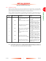
carrier in writing within three days; state the Item Number of the pump together with your order
number and your supplier's invoice number. Retain all packing materials for inspection. Do not use the
pump if it is damaged.
Check that your package contains the items listed in Table 12. If any of these items is missing, notify your
supplier in writing within three days.
If the pump is not to be used immediately, store the pump in suitable conditions, following the procedure
described in Section 6.1.
Do not discard the packing materials; retain them to re-package the pump should you need to return it
for service.
Quantity Description
1
DX pump with inlet-screen fitted
1
Inlet seal (either trapped O-ring, Co-seal or copper compression gasket suitable
for the inlet-flange type)
1
Connector (24 V) - for driving accessories from Podule socket
1
Inlet-strainer (iDX fitted in the NW25 interstage port only)
Check (3)
Table 12 – Checklist of components
Note: An inlet-strainer is not available for the NW16 interstage port of the EXT75iDX.
3.2
Typical installation
A typical pumping system with a DX pump is shown in Figure 5.
The accessories available for the DX pumps are detailed in Section 7.4; the accessories are shown in
Figure 10.
3.3
Connection to the vacuum system
WARNING
Ensure that all wires and piping are routed appropriately to avoid the risk of tripping.
WARNING
Install the pump in the vacuum system before the logic interface cable is connected to the
control equipment and before the electrical supply is connected. This will ensure that the
pump cannot operate accidentally causing injury to people.
We recommend that the system is leak tested after installation has been completed.
Issue D
23
20.06.06
INSTALLATION
Take care when you unpack the pump to avoid excessive shocks that could damage the bearings and
reduce the life of the pump. The pump is supplied with the inlet and outlet sealed to prevent entry of
dust and vapour. Do not remove these seals until you are ready to install the pump on your vacuum
system.
EXT Compound Turbomolecular Pumps
PAGE
24
INSTALLATION
1.
Vacuum system
10.
Rotary backing pump
2.
High-vacuum gauge
11.
Mist filter
3.
Vibration isolator
12.
Vent valve
4.
Inlet-screen
13.
Alternative position for vent valve
5.
DX pump
14.
Air cooler
6.
Backing valve
15.
PRX purge restrictor
7.
Vacuum gauge
16.
Regulated purge gas supply
8.
Flexible bellows
17.
WCX water-cooler and connections
9.
Foreline trap
Figure 5 – Typical pumping system with a DX pump
Issue D
24
20.06.06
EXT Compound Turbomolecular Pumps
3.3.1
Inlet-screen (supplied fitted)
PAGE
25
WARNING
Removal of the inlet-screen will expose the risk of injury from sharp edges.
It is not possible to remove the inlet-screen from a pump with an NW40 inlet-flange (EXT75DX only).
To remove the inlet-screen from a pump with an ISO or CF inlet-flange, use a bent wire hook or small
screwdriver to carefully lever the inlet-screen out from the inlet-flange.
To replace an inlet-screen, locate it as centrally as possible over the ISO or CF inlet-flange and then, with
your fingers spread evenly around the edge of the screen, push it firmly downwards. If they are not
already in place, the tangs must be snapped into the locating groove in the inlet-flange using a suitable
tool to press them into position.
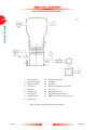
1.
EXT inlet-flange
2.
Inlet-screen
Figure 6 – Correct installation of the inlet-screen (EXT75DX)
1.
EXT inlet-flange
2.
Inlet-screen
Figure 7 – Correct installation of the inlet-screen (EXT255DX)
Issue D
25
20.06.06
INSTALLATION
Do not remove the inlet-screen unless you can be sure that there is no danger that debris can fall into
the pump. If the inlet-screen is removed, the pumping speed will increase by up to 10%. Do not remove
the inlet-screen until you are ready to mount the pump onto your system, since the screen protects you
from exposure to sharp edges.
EXT Compound Turbomolecular Pumps
3.3.2
Mechanical fixing
PAGE
26
WARNING
INSTALLATION
Do not operate the pump until it is securely fixed. If the pump seizes, the stored energy
of the rotor can cause rapid movement of the pump, which may cause further damage and
injury to people.
There are two ways in which the DX pumps can be securely fixed. The ideal fixing for a DX pump is via
its inlet flange to a rigid, firmly fixed vacuum system - refer to Section 3.3.3. If this is not possible because
of the nature of the vacuum system then the base of the pump must be fixed to a firm support, refer to
Section 3.3.4 for instructions on base mounting the pump.
3.3.3
Inlet-connection and orientation
The pump can be securely fixed to the vacuum system via the inlet-flange. The pump can be mounted in
any attitude from the vertical and upright through to horizontal (±2°). If the pump is mounted
horizontally, and you are using a rotary vane pump to back your DX pump then the backing port must
point vertically downwards (±20°) to reduce the risk of contamination from the backing pump oil.
Make sure that the pump-inlet and all components fitted to the pump-inlet are clean and dust-free. If the
pump-inlet is not kept clean, the pump-down time may be increased.
The inlet connections for the EXT75DX are CF flange, ISO flanges and the NW flange. The inlet
connections for the EXT255DX are CF flange and the ISO flange:
•
If the pump has a CF flange, use the copper compression gasket supplied with the pump and use a
full complement of bolts to connect the inlet-flange of the pump to the vacuum system.
•
If the pump has an ISO flange, use the Edwards trapped O-ring supplied with the pump and use a
minimum of four claw clamps (each torqued to 10 Nm) to connect the inlet-flange of the pump to
the vacuum system. Alternatively, use a rotatable collar and the trapped O-ring supplied with the
pump to connect the inlet-flange of the pump to the vacuum system; use a full complement of bolts
with the rotatable collar.
•
If the pump has an NW flange, use the centring ring supplied with the pump and a metal NW clamp
to connect the inlet-flange of the pump to the vacuum system. In this case you must fix the base of
your pump to a firm support, as described in Section 3.3.4.
All inlet flange bolts must be re-tightened once the system is under vacuum. Ensure that no torques or
other forces are transmitted to the pump from the vacuum system or the associated pipelines. If
necessary, fit an inlet vibration isolator between the pump inlet and the vacuum system (refer to Section
7.4). In this case you must fix the base of your pump to a firm support, as described in Section 3.3.4.
3.3.4
Base Mounting
The base of the DX pump can be fixed to a firm support using the tapped fixing holes. Refer to Figures
1 and 2 for fixing hole details.
Note: For EXT75DX only, the four screw-in rubber feet must be removed from the four tapped fixing holes
before the pump can be base mounted.
Issue D
26
20.06.06
EXT Compound Turbomolecular Pumps
We advise the following requirements should be met to ensure the pump remains secure in the event of
a total pump seizure:
PAGE
27
Support must withstand a destructive torque of: 333Nm (EXT75DX)
620Nm (EXT255DX)
To ISO898-1 strength class 12.9
(nom. tensile strength 1200MPa)
Screw engagement length:
6mm minimum
Fastening torque:
6Nm (0.61 kgf.m) (EXT75DX)
12Nm (1.22 kgf.m) (EXT255DX)
This method of fixing must be used if your pump supports the weight of the vacuum system. The weight
of the vacuum system must be no more than 10kg for EXT75DX and 20kg for EXT255DX.
3.3.5
Backing connection
WARNING
Ensure safe ducting of the backing line if oil mist or hazardous substances are present.
WARNING
To avoid over pressurising the pump, the exhaust line should be restricted when venting
from a positive pressure gas supply.
CAUTION
Do not use the DX pumps with a backing pressure below 5 x 10⁻⁴ mbar (5 x 10⁻² Pa). Lower backing
pressures will increase the evaporation rate of the lubricating oil and so may reduce the life of the
bearings.
Use suitable vacuum tubing and connectors to connect the NW flange of the backing-port to your
backing-pump. If necessary, use flexible pipe or bellows to reduce the transmission of vibration from the
backing-pump to the DX pump.
We recommend that you use a BOC Edwards EM, RV or XDS Scroll backing-pump. The recommended
size of backing-pump required is indicated in Table 3. A larger or smaller backing-pump may also be
suitable, depending upon the application is intended for.
The DX pumps are suitable for use with diaphragm backing-pumps although the effect of higher backing
pressure on the pump's performance and cooling requirements should be noted. Refer to Table 3 and
Section 2.1.
3.3.6
Interstage connection (iDX variants only)
Use suitable vacuum tube and connectors to connect the interstage-port to your vacuum system or to
the outlet flange of another turbo or compound turbomolecular pump (if using an iDX pump to back
another pump). Leave the inlet-strainer in the interstage-port, unless you are sure that debris cannot be
drawn into the interstage-port.
Note: The EXT75iDX with NW16 interstage-port is not supplied with an inlet-strainer fitted.
Issue D
27
20.06.06
INSTALLATION
Fixing screws:
EXT Compound Turbomolecular Pumps
PAGE
28
3.4
Purge gas connection
3.4.1
Connect the purge gas
INSTALLATION
To supply a purge gas to the pump, remove the plug fitted in the purge-port, fit a vent-port adaptor (refer
to Section 7.4) and connect the purge gas supply to the vent-port adaptor. The purge gas must comply
with the specification given in Section 2.4.
3.4.2
Recommended purge gas flow
The recommended purge gas flow for typical applications is 25 sccm (0.42 mbar l s-1, 42 Pa l s-1). This
flow will protect the pump when pumping oxygen in concentrations above 20% by volume.
The flow rate of the purge gas must be limited to the allowed range, specified in Section 2.4. To limit the
flow rate, use a flow controller or a pressure regulator and calibrated flow restrictor. The PRX10 purge
restrictor accessory (refer to Section 7.4) is suitable for this purpose. Adjust the PRX10 as described in
the instruction manual supplied with the accessory.
3.5
Electrical installation
3.5.1
Introduction
WARNING
You must make sure that the pump is electrically bonded to earth. If you do not, the
system could become hazardous live in the event of a live conductor touching a metallic
surface.
The electrical installation must be carried out by a suitably-qualified person. Always make the electrical
connections to the DX pump after the pump has been installed on your vacuum system.
Earth the pump using the connection provided and refer to Section 3.5.2.
You can operate the DX pump using the BOC Edwards TIC Turbo Instrument Controller or TIC Turbo
Controller, refer to Section 3.5.3. You can also control the DX pump using your own system, refer to
Section 3.5.4 for information about control and to Section 3.5.5 for instructions on how to connect your
electrical supply.
3.5.2
Earth (ground) connections
We recommend that you fit a separate earth (ground) conductor to earth the DX pump. Use an uninsulated braid or a separate insulated green/yellow conductor, and use the M5 x 10 screw and shake
proof washer supplied (fitted to the earth hole on the pump) to secure the earth conductor to the pump.
The impedance between the pump-body and the earth connection point must be < 0.1 Ω.
3.5.3
Connect the logic interface to the TIC
If you are using the BOC Edwards TIC Turbo Instrument Controller or TIC Turbo Controller to power
and control your pump, the DX pump logic interface cable connects directly into the back of the TIC.
Refer to the TIC Instruction Manual for further information.
Issue D
28
20.06.06
EXT Compound Turbomolecular Pumps
3.5.4
Connect the logic interface to your control equipment
You can control the DX pump using a hardware parallel control interface and via commands sent over
a serial interface
If you wish to control the DX pump using the hardware Parallel Interface, refer to Section 3.6 for more
information. If you wish to use the Serial Interface, see the instructions given in Section 3.7. The logic
interface provides the facility to work in either Parallel or Serial control modes: however, you cannot
send commands in both modes simultaneously, refer to Section 3.7.6.
3.5.5
Connect the electrical supply
WARNING
This product requires a separate power supply (not included). The power supply should
be adequately protected against a hazardous live condition (for example, in case of a short
circuit).
WARNING
Incorporate a suitable isolation device in the electrical supply. Locate the switch in an
easily accessible position and mark it as the disconnecting device for the DX pump. If you
do not, you will not be able to switch off the DX pump in an emergency.
WARNING
Incorporate a suitable fuse or current limiting device, as specified in Section 2.8, in the 24V
supply line to the DX pump. If you do not and a fault develops, the DX pump may develop
a hazardous surface temperature or present a fire hazard.
WARNING
Do not exceed the maximum supply voltage. Excessive supply voltage will cause
permanent damage to the control electronics and may result in a mechanical hazard in
some failure conditions.
CAUTION
When connecting the DX pump to the power supply, ensure that all 3 pins for the 24 V connection and
all 3 pins for the 0 V connection on your connector mating half are connected to the power supply.
Refer to Figure 8 for a schematic diagram of the logic interface connections.
The electrical supply you provide for the DX pump must meet the requirements of BS EN 61010-1 /
C22.2 1010-1. Ensure that hazardous voltages as defined in EN61010 cannot be present on the electrical
interface to the DX pump.
Issue D
29
20.06.06
PAGE
29
INSTALLATION
If you wish to operate the DX pump using your own control system, use a suitable connector mating half
(not supplied), to connect your control equipment to the connector on the logic interface cable (refer
to Table 7). When you make the electrical connections to the DX pump described in the following
sections, refer to table 8 for full details of the logic interface connector pins.
EXT Compound Turbomolecular Pumps
The DX pump 0V is not referenced to earth (ground). Ensure that the electrical supply offers a path (<
22 kΩ) between 0V and earth.
PAGE
30
Refer to Table 8 - Logic Interface Connector Pins when you connect the electrical supply to your
connector mating half.
INSTALLATION
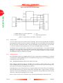
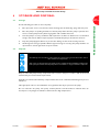
1.
24V dc electrical supply
6.
DX pump logic interface
2.
Fuse
7.
Start switch
3.
Optional LED indicator - system ok
8.
Optional standby switch
4.
Optional LED indicator - normal speed
9.
Optional voltmeter to monitor analogue output
5.
Current limit resistor for LED
Figure 8 – Logic interface connections - parallel mode
3.6
Parallel interface mode
CAUTION
If you use the Normal and Fail lines to drive the coils of d.c. relays you must include a back EMF
suppression diode in parallel with each relay coil to protect the DX pump.
1.
Connect your control equipment to the control input pins of your logic interface mating half. Refer
to Table 8, which identifies the Logic Interface connector pins. The control inputs are as follows:
•
Start
•
Standby Speed
To activate either of these control inputs, you must connect the control input pin to the 0V control
reference.
For example, to start the pump, connect pin 3 (Start / Stop) to pin 2 (0V Reference). To stop the pump,
break the connection between pin 3 and pin 2.
Issue D
30
20.06.06
EXT Compound Turbomolecular Pumps
Note: Serial Enable is also a control input but is not required in a system operating purely in Parallel Mode. Make
sure that there is no connection to Serial Enable (pin 5).
2.
To monitor Analogue Output, connect your control equipment to the pump Analogue Output (pin
9) and to pin 2 of your logic interface mating half.
3.7
3.
To monitor the Normal status output, connect your control equipment to the Normal status
output (pin 15) and to pin 2 of your logic interface mating half. You can use the output to control
other devices in your pumping system. The output can drive a low power relay of up to 24V coil
rating.
4.
To monitor the Fail status output, connect your control equipment to the Fail output (pin 7) and
to pin 2 of your logic interface mating half. You can use the output to control other devices in your
pumping system. The output can drive a low power relay of up to 24V coil rating.
Serial interface mode
The Serial Interface allows you to control the DX pump and to interrogate its operational status using a
number of commands. There is a multi-drop mode that allows you to communicate with more than one
DX pump whilst using just one control system.
3.7.1
Connect the serial interface to your control equipment
CAUTION
When connecting the DX pump to a PC, remember that the 0 V pin on the RS232 connector may well
be connected to earth through the PC. If this is the case ensure that the 0 V rail of the 24 V supply is
not also connected to earth at some other point such as at the power supply. If you do not wish to have
the 0 V rail of the 24 V supply connected to earth at the PC an opto-isolated interface to the PC should
be used.
The DX pump can connect directly to the RS232 serial input on a PC as shown in Figure 9. In this
configuration the PC is the serial link master and the DX pump is the slave. The distance over which the
serial link will work is dependent on any difference in voltage between the 0V at the sending and receiving
end. If the 0V reference at the receiving end is within 0.3V of the 0V Control Reference pin on the DX
pump control connector then the serial link should be capable of operating at distances up to 6m. An
interface circuit external to the DX pump may be required for longer distances.
The software in the DX pump is capable of operating with several pumps connected to a single serial link
master. This is referred to as multi-drop mode. However, the serial interface driver in the DX pump is
based on the RS232 standard, which is only intended for point to point serial links. Some additional
hardware will be required to link several DX pump units to a single serial link master. A concept drawing
of one possible arrangement is shown in Figure 10.
Issue D
31
20.06.06
INSTALLATION
When you receive your pump, the Analogue Output will be configured to monitor pump rotational
speed. If you wish to monitor any other parameter you must re-configure your DX pump using
commands over the Serial Interface. Refer to Section 3.7 for further details.
PAGE
31
EXT Compound Turbomolecular Pumps
PAGE
32
INSTALLATION
1.
RS232 interface on control equipments
3.
Fuse
2.
24V dc electrical supply
4.
DX pump logic interface
Figure 9 – Logic interface connections - serial mode
3.7.2
Serial enable
To send a Serial message you must first activate Serial Enable. This is achieved by linking the Serial Enable
input signal (pin 5) to pin 2 of your logic interface mating half. We recommend that you incorporate this
link into your Serial communications cable so that the Serial Enable is only activated when the serial cable
is connected. When you subsequently remove the cable, Serial Enable will become inactive.
Serial Enable acts as an interlock for commands sent over the Serial Interface. If the pump is running
(having been sent a Serial Start command) and the Serial Enable subsequently becomes inactive, the pump
will trigger a fail condition and will decelerate to rest. To clear this fail condition, you must re-activate
the Serial Enable and send a Serial Stop command.
3.7.3
Serial protocol
The Serial Interface link is set to 9600 Baud, 8 bits, 1 stop, no parity with no handshaking. The commands
are made up from printing ASCII characters. The maximum message size you can send is 80 characters,
including start and end characters.
Note: All alphabetical characters must be sent in upper case format.
Every complete command message you send will receive a response - either a status code or a data
return. The DX pump can only deal with one message at a time. It will only accept a new message once
the response to the previous message has been returned.
If the DX pump receives characters that are not framed inside start and stop characters, it will ignore
them. Messages with the stop character missing will be discarded with no response when a new start
character is received. If the DX pump receives an unrecognisable message between the start and stop
characters, it will return an appropriate error message.
Refer to Section 3.7.7 for more information about operating the DX pumps in multi-drop mode.
Issue D
32
20.06.06
EXT Compound Turbomolecular Pumps
PAGE
33
INSTALLATION
1.
RS232 interface on control equipment
2.
Buffer
3.
DX pump
4.
OR gate
Figure 10 – Conceptual diagram for multi-drop connection
3.7.4
Message structure
To communicate a message to the DX pump you must send the characters in a specific order. If the
message does not conform to the correct structure it will be ignored and no reply will be sent.
The correct structure to use is as follows:
Issue D
•
a valid start character, either a '!' character for a store operation or a '?' character for a query
operation, followed by
•
a command, which will be an upper case alphabetical character, followed by
•
an object number, comprising three decimal digits, followed by
33
20.06.06
EXT Compound Turbomolecular Pumps
PAGE
34
•
for some commands only, a data field, comprising a sequence of characters separated from the
object number by a space, followed by
•
a terminating carriage return
The message protocol in multi-drop mode is marginally different, refer to Section 3.7.7.
INSTALLATION
3.7.5
Command set
Table 13 shows a summary of the full set of commands available for controlling and monitoring the DX
pump.
Table 14 shows the abbreviations that are used to define commands in the following sections and Table
15 shows the error codes that might be returned.
3.7.6
Simultaneous parallel and serial operation
You can control the pump using Parallel Interface control inputs and at the same time monitor various
pump parameters using the Serial Interface. Alternatively you can control the pump using commands
sent over the Serial Interface while at the same time you can monitor the Normal signal and Analogue
Output over the Parallel Interface. Figure 11 shows a schematic diagram of a system that would allow
you to do this.
You cannot control the pump using both the Parallel and Serial Interfaces simultaneously. For example,
if you start the pump by sending a Start command over the Serial Interface you cannot then stop the
pump by using the Start /Stop switch on the Parallel Interface. The pump will ignore the state of the Start
/ Stop switch on the Parallel Interface. To stop the pump you must send a Serial Stop command. Only
when the Serial Stop command has been received by the pump can any commands sent via the Parallel
Interface be acted on.
Similarly, if you Start the pump by using the Start switch on the Parallel Interface you cannot then stop
the pump by sending a Stop command over the Serial Interface. The pump will ignore any Start or Stop
commands received over the Serial Interface. To stop the pump, you must use the Parallel Stop switch.
Only when the pump has been stopped using the Parallel Interface switch will any Start or Stop
commands be accepted via the Serial Interface.
Issue D
34
20.06.06
EXT Compound Turbomolecular Pumps
Object
name
Command
Parameter Factory
range
setting
Data
type
Units Comments
PAGE
35
!S850
?S850
0.99
-
Pump type
?S851
7;
10;
4
-
string
string
string
chars
chars
chars
Pump
control
!C852
0
1
-
decimal
-
?V852
0.1800;
32-bits
-
decimal
hex
RPS
flags
!S853
?S853
0
1
0
decimal
-
decimal minute Timeout period for both initial ramp up and
s
if speed drops below 50%
Vent options
decimal address Multi-drop address
0 = disable multi-drop address
99 = wildcard
2
3
4
5
6
7
8
Pump type
DSP software version number
(D39647631x for EXT75DX)
and D39648601x for EXT255DX)
Full speed RPS (1500 for EXT75DX and
1000 for EXT255DX)
Stop the pump
Start the pump
Measured motor speed
System status word
Hard vent only when <50% speed
Controlled vent if >50% speed
or hard vent if <50% speed
Hard vent if stop
or hard vent if fail and <50% speed
Hard vent if stop
or controlled vent if fail and >50% speed
or hard vent if fail and <50% speed
Hard vent if fail
or hard vent if stop and <50% speed
Hard vent if fail
or controlled vent if stop and >50% speed
or hard vent if stop and <50% speed
Hard vent if stop or fail
Same as option 6
Vent = Permanently Enabled (Fan)
Timer
setting
!S854
?S854
1.30
8
Power limit
setting
!S855
?S855
50.120
80.200
80
160
decimal
decimal
watts
watts
Normal
speed
setting
!S856
?S856
50.100
80
decimal
%
Normal speed as a percentage of full speed
Standby
speed
setting
!S857
?S857
55.100
70
decimal
%
Standby speed as a percentage of full speed
Temperature
readings
?V859
0.100;
0.100
-
decimal
decimal
o
Measured motor temperature
Measured controller temperature
Link
parameter
readings
?V860
0.500;
0.300;
0.15000
-
o
C
C
Link power maximum EXT75DX
Link power maximum EXT255DX
decimal 0.1volts Measured link voltage
decimal 0.1amp Measured link current
Measured link power
decimal
s
0.1watt
s
Table 13 – Summary of commands that can be sent to the DX pump
Issue D
35
20.06.06
INSTALLATION
Node
EXT Compound Turbomolecular Pumps
Object
name
PAGE
36
Command
Parameter Factory
range
setting
Data
type
Units Comments
INSTALLATION
Factory
settings
!S867
1
-
-
-
Reset all configuration options and
parameters to the factory settings
PIC software
version
?S868
10
-
string
chars
Speed
control
!C869
0
1
-
decimal
-
Set target speed to full speed
Set target speed to standby speed
Timer
options
!S870
?S870
0
1
1
decimal
-
Timer = disabled
Timer = enabled
Note that the timer is permanently enabled
on ramp-up.
Analogue
signal
options
!S871
?S871
0
1
2
3
0
decimal
-
Analogue output = Measured speed
Analogue output = Measured power
Analogue output = Measured motor temp.
Analogue output = measured control temp.
Electronic
braking
option
!S872
?S872
0
1
0
decimal
-
Electronic braking = disabled
Electronic braking = enabled
Close vent
valve
!C875
1
-
decimal
-
Closes the vent valve for delayed start and
overrides the current vent option. There is
no open vent valve command but the stop
command (!C852 0) will clear the override.
PIC software version number
(D39647620x)
Table 13 – Summary of commands that can be sent to the DX pump (Continued)
Abbreviation
cr
chars
d
h
r
sp
string
X
Meaning
carriage return character
characters
decimal ASCII character
Note:
Fields showing multiple d characters are to indicate typical length. All data fields have a
maximum of 5 decimal characters (prefixed by a minus number for negative numbers).
hexadecimal ASCII character
Returned error code - refer to Table 15
space character
may have several ASCII characters
Multi-drop decimal ASCII character
Note:
Fields showing multiple X characters are to indicate maximum length and not fixed length.
Table 14 – Command abbreviations
Returned error code
0
1
2
3
4
Meaning
No error
Invalid command for object ID
Invalid Query/Command
Missing parameter
Parameter out of range
Table 15 – Error codes
Issue D
36
20.06.06
EXT Compound Turbomolecular Pumps
Returned error code
5
Meaning
Invalid command in current state - e.g. serial command to start/stop when in
parallel control mode
PAGE
37
Table 15 – Error codes
INSTALLATION
1.
RS232 interface on control equipment
7.
Optional serial mode selector
2.
24V d.c. electrical supply
8.
DX pump
3.
Fuse
9.
Optional voltmeter
4.
Optional LED indicator - system OK
10.
Optional serial enable switch
5.
Optional LED indicator - normal speed
11.
Optional standby switch
6.
Current limit resistor for LED
12.
Start switch
Figure 11 – Schematic diagram of the logic interface connections
3.7.7
Multi-drop mode
Using multi-drop mode, you can communicate with more than one DX pump using a single computer
system. Each DX pump must be assigned its own individual address before it can be fitted into a multidrop system. The command to assign the multi-drop address is sent in standard DX message format (as
detailed in Section 4.1.10.
The message protocol in multi-drop mode is marginally different to that described for serial messages in
single pump systems. The main differences in multi-drop message protocol are detailed below:
Issue D
37
20.06.06
EXT Compound Turbomolecular Pumps
PAGE
38
INSTALLATION
•
All multi-drop commands, queries or replies have the first character #.
•
All commands, queries and replies contain a header containing the address of the node that the
message is to, followed by the address of the node that the message is from.
•
There is a delimiter character : (colon) which separates the two multi-drop addresses in the header.
•
The remainder of the message (command, query or reply) follows the same protocol as already
described for single pump systems.
•
The wild card address 99 is very useful and means ‘any’ node.
After a DX pump has been assigned a multi-drop address, it will ignore any messages in the format for
single pumps. An individual DX pump will remain silent and ignore all command messages unless the
multi-drop address matches its own address.
3.8
Vent options, vent valve connection and control
CAUTION
If the pump is vented when it is at full rotational speed and the rate of pressure rise is too high, the
pump could be damaged and its life may be reduced. We therefore recommend that either the rate of
pressure rise is limited (refer to Figure 3) or that the vent valve is only opened after the DX pump speed
has fallen to 50% of full rotational speed.
To maintain the cleanliness of your vacuum system, we recommend that, whenever you switch the pump
off, you vent the pump (or vacuum system) when the speed of the DX pump is between full rotational
speed and 50% of full rotational speed. Over this speed range, the rotor spins fast enough to suppress
any backstreaming of hydrocarbon oil from your backing pump.
Do not connect the vent-valve to the backing pipeline, this may lead to contamination. Connect the inlet
of the vent-valve to the vent gas supply (refer to Section 2.3 for the vent gas specification).
Venting may be accomplished by using one of the following methods described in Sections 3.8.1 to 3.8.4.
3.8.1
Manual vent valve
A manual vent-valve is supplied with the DX pump. It is not possible to accurately control the rate of
pressure rise using the manual vent valve so take care not to open it too quickly. We recommend that
you open the manual vent-valve only after the pump speed has fallen to 50% of full rotational speed.
3.8.2
TAV5 or TAV6 solenoid vent valve
The TAV5 and TAV6 solenoid valves can be purchased as accessories – see Section 7.4. The solenoid
valves can be used in the following ways:
•
Use a TAV5 or TAV6 solenoid valve in place of the manual vent valve on the pump
•
Use a TAV5 or TAV6 solenoid valve connected to a convenient flange on your vacuum system
If you connect a vent valve to your vacuum system, select a point upstream of the DX pump to prevent
backstreaming of oil from the backing pump.
If using the TAV5 vent-valve, the pump may only be hard vented when it is at full speed if the vacuum
system has a volume of 5 litres or more. If using the TAV6 vent-valve, the pump may only be hard vented
when it is at full speed if the vacuum system has a volume of 10 litres or more.
Issue D
38
20.06.06
EXT Compound Turbomolecular Pumps
If the volume of your vacuum system is less than 5 litres (when using a TAV5 vent-valve), or if the volume
of your vacuum system is less than 10 litres (when using a TAV6 vent-valve), you can incorporate a
suitable vent-restrictor and vent the pump when it is at full speed. Table 17 gives an indication of the
appropriate orifice size to be fitted to the vent valve for given vacuum system volumes in order that the
rate of pressure rise remains within the limits shown in Figure 3.
3.8.3
Controlled venting
The TAV5 or TAV6 solenoid valve can be controlled by the Podule electronics. To use this function, fit
the electrical connector supplied with the pump to the lead of the TAV5 or TAV6 solenoid valve. To
ensure cable cores and screen are wired correctly, follow the electrical connection instructions given in
the Accessories Manual (supplied with the TAV valve) and refer to Figure 4 and Section 2.9. Plug the
connector into the socket at the top of the Podule (refer to Figures 1 and 2, items 1 and 7 respectively).
The Podule is capable of controlling a number of different venting options, these are defined in Table 16.
Option number
0
1
2
3
4
5
6,7
Description of vent function
Vent valve opens fully below 50% full rotational speed for either Stop command
or Fail.
Note: this is the factory default setting.
Controlled venting from 100% to 50% full rotational speed;
vent valve opens fully below 50% for either Stop command or Fail.
Vent valve fully opens immediately Stop command is received;
vent valve opens fully below 50% full rotational speed if Fail.
Vent valve fully opens immediately Stop command is received;
Controlled venting from 100% to 50% full rotational speed if Fail then vent
valve opens fully below 50%
Vent valve fully opens immediately if Fail;
vent valve opens fully below 50% full rotational speed if Stop.
Vent valve fully opens immediately if Fail;
Controlled venting from 100% to 50% full rotational speed if Stop command
received then vent valve opens fully below 50%
Vent valve fully opens immediately for either Stop command or Fail.
Table 16 - Vent options
When you receive your pump, the Podule will be configured with the factory default vent option 0, as
detailed in Table 16. You can configure your Podule to one of the other venting options provided you
can send commands via the Serial Interface or you have access to a BOC Edwards TIC Turbo and
Instrument Controller or Turbo Controller.
The Podule only energises (‘shuts’) the TAV solenoid valve when it receives a Start command. Prior to
that, the valve will be in the ‘open’ vent state. If you have a large vacuum system, you may wish to allow
the backing-pump to reduce the pressure in the system to an acceptable level before starting the DX
pump. In this case, you can send a command via the Serial Interface to close the vent valve before you
send a Start command - this is known as a delayed start.
If you are controlling your DX pump with a BOC Edwards TIC Turbo and Instrument Controller or TIC
Turbo Controller, you can drive your TAV solenoid valve from the TIC. Refer to the TIC Instruction
Manuals for more information.
Issue D
39
20.06.06
INSTALLATION
Note: If you use a vent-restrictor, you may find that the time required to vent your vacuum system is unacceptably
long. You may be able to reduce the vent time if you use a vent-valve without a vent-restrictor and wait
until the pump speed has fallen to 50% of full rotational speed before you open the vent-valve.
PAGE
39
EXT Compound Turbomolecular Pumps
3.8.4
PAGE
40
Alternative valve connected to the vacuum system
INSTALLATION
If using another vent-valve, ensure that a suitable vent-restrictor is fitted to your vacuum system to limit
the rate of pressure rise. Refer to Table 17 for information about vent-restrictor sizes. If you do not fit
a suitable vent-restrictor, you must open the vent-valve only after the speed of the pump has fallen to
50% of full rotational speed.
Vacuum system volume (litres)
Orifice diameter (mm)
<20
≤1.0
<10
≤0.7
<5
≤0.5
<2
≤0.35
Table 17 – Vent-restrictor orifice diameter (with atmospheric pressure at the inlet of the vent-valve)
3.9
Cooling
3.9.1
Introduction
CAUTION
You must ensure that the pump is adequately cooled to prevent damage to the rotor and bearing.
3.9.2
•
Natural Convection Cooling: For some light pumping duties, with an ambient air temperature less
than 30°C, natural convection cooling may be adequate to cool the DX pump.
•
Forced Air Cooling: The ambient air temperature when using forced air cooling must be 5°C to
35°C. You must ensure that there is an adequate supply of cooling-air to the pump.
•
Water-Cooling: You must use water-cooling with an ambient air temperature greater than 35°C
or when using a bakeout band (CF variants only). When using water-cooling, ambient air
temperature must be less than 40°C and the water temperature must be between 10°C and 20°C.
•
We recommend that whereever possible, you cool the pump by forced air cooling or watercooling. See Table 3, page 13 for further performance information.
Forced air cooling
Air-cooling accessories are available for DX pumps (refer to Section 7.4). Fit the air-cooler as described
in the instruction manual supplied with it. If you wish to use an alternative fan for air-cooling, ensure that
the flow rate is above 70 m3h-1 (40 cfm).
The air-cooler can be powered by your own external power supply, the BOC Edwards TIC Turbo and
Instrument Controller, the TIC Turbo Controller or by the Podule. It cannot be powered by the Podule
if a TAV solenoid valve is already connected to the Podule. Follow the electrical connection instructions
in the air-cooler manual to wire the lead of the air-cooler into the Podule connector supplied with the
pump (refer to Figure 1). Plug the connector into the socket at the top of the Podule (refer to Figures 1
and 2, items 1 and 7 respectively).
You can only configure your Podule to drive an air-cooler if you can send commands via the Serial
Interface or you have access to a BOC Edwards TIC Turbo and Instrument Controller or Turbo
Controller.
Issue D
40
20.06.06
EXT Compound Turbomolecular Pumps
3.9.3
Water-cooling
PAGE
41
CAUTION
A WCX water-cooler accessory is available for the DX pumps (refer to Section 7.4). Apply a thin layer
of thermal grease to the mounting face of the water-cooler then fit it as described in the instruction
manual supplied with it. The cooling-water supply must comply with the specification given in Section 2.5.
Pipes in the water-cooling circuit may become blocked if the cooling-water contains too much calcium
carbonate or if it contains particles that are too large. Corrosion of the water-cooling circuit may occur
if there is too little calcium carbonate and oxygen in the water. Good quality drinking water is usually
suitable. If in doubt, check the quality of your cooling-water supply and, if necessary, provide treatment
and filtration.
Connect the cooling-water supply to the water-cooler on the pump as described below. Either of the
two riffled connectors on the water-cooler can be used for the water supply or return connections.
Push reinforced hose (approximately 6mm internal diameter) over the ends of the riffled hose
connectors on the water-cooler on the pump. Attach the hose with strong hose clips and make sure that
they are tightened securely. Alternatively, unscrew the riffled hose connectors and remove them from
the water-cooler and make direct connections to the 1/8 inch BSP female threaded fittings on the watercooler.
If you want to remove the pump for maintenance, and you do not want to break the cooling-water circuit,
unscrew the two M4 fixing-screws and remove the water-cooler from the pump. Make sure that there
is a layer of thermal contact grease on the water-cooler before you refit it to the pump.
Issue D
41
20.06.06
INSTALLATION
You must turn off the cooling-water when you switch off the pump to prevent condensation inside the
pump and Podule.
EXT Compound Turbomolecular Pumps
PAGE
42
INSTALLATION
This page intentionally blank.
Issue D
42
20.06.06
EXT Compound Turbomolecular Pumps
4
OPERATION
PAGE
43
WARNING
Before operating the pump, it is worthwhile configuring the various Podule settings so that they are
suitable for your application.
If your system is designed to operate in pure Parallel Interface Mode, you will not have the facility to
change any of the Podule settings once the DX pump is installed on your system. The pump is supplied
with all settings at factory default values, as shown in Table 13. If you wish to change any of the Podule
settings, make sure you do this separately before installing the DX pump on your system.
To configure the DX pump you could use your own serial system. Section 4.1 details the commands that
you will need to configure the Podule. Alternatively you could use the BOC Edwards TIC Turbo and
Instrument Controller or TIC Turbo Controller. Further information regarding this is detailed in
Section 4.2.
If you intend to operate the DX pump in pure Parallel Interface Mode and you do not wish to reconfigure
the Podule settings, go straight to Section 4.3.
4.1
Configuring the DX pump using Serial Commands
Refer to Table 13 for a summary of the full set of serial commands. Table 13 details the parameter range
and factory default for each setting. The following sections describe the settings in more detail.
4.1.1
Power limit setting
Table 18 shows the power limit setting options for the DX pumps. The pump is supplied to you with a
default power limit as shown. If this limit is not suitable for your application, you can change it to any
value between the maximum and minimum shown.
Pump
Maximum value
setting
Minimum value
setting
Default power
setting
EXT75DX
120W
50W
80W
EXT255DX
200W
80W
160W
Table 18 – Power limit setting
Send the command as follows (where the 'd' characters represent the value in Watts that you are trying
to set. For example, if you want to set the limit to 90W, type 90).
Command
!
S
8
5
5
sp
d
d
d
cr
The reply you receive will be in the following format:
Reply
*
S
8
5
5
sp
r
cr
The Power Limit Setting is now stored in memory within the DX pump.
Issue D
43
20.06.06
OPERATION
Do not operate the DX pump unless it is connected to your vacuum system. If you do,
the pump rotor can cause injury. The pump rotor rotates at very high speeds and the
rotating blades might not be visible.
EXT Compound Turbomolecular Pumps
To check what power limit is set, you can send a query as follows:
PAGE
44
Command
?
S
8
5
5
cr
The reply you receive will be in the following format:
OPERATION
Reply
4.1.2
=
S
8
5
5
sp
d
d
d
cr
Powering a fan from the Podule
You can power a fan from the DX Podule, provided that you are not already using the Podule to control
a vent valve.
To enable the fan, send the following command:
Command
!
S
8
5
3
sp
8
cr
3
sp
r
cr
The reply you receive will be in the following format:
Reply
*
S
8
5
The permanently enabled fan setting is now stored in memory within the DX pump.
When you receive the pump, it will be set-up to run a vent valve. You can send a query to find out what
the setting is as follows:
Command
?
S
8
5
3
cr
The reply you receive will be in the following format:
Reply
=
S
8
5
3
sp
d
cr
If the character 'd' is 8, then the fan is enabled. If it is anything else, you will need to configure the Podule
to run the fan.
4.1.3
Controlled venting options
If you are using the Podule to automatically control a vent valve, there are a number of varied venting
options you can choose from, refer to Table 16.
To set a vent option, send the following command, (where the character 'd' refers to the option number
shown in Table 16):
Command
!
S
8
5
3
sp
d
cr
3
sp
r
cr
The reply you receive will be in the following format:
Reply
*
S
8
5
The Venting Option is now stored in memory within the DX pump.
Issue D
44
20.06.06
EXT Compound Turbomolecular Pumps
To check what Venting Option is set, you can send a query as follows:
Command
?
S
8
5
3
PAGE
45
cr
The reply you receive will be in the following format:
4.1.4
=
S
8
5
3
sp
d
cr
Standby speed setting
The pump can be run at Standby Speed rather than full rotational speed. The Standby Speed is a user
configurable option and can be set to any value between 55% and 100% full rotational speed. When you
receive the pump, it will be configured with a standby speed of 70% full rotational speed.
To change the Standby Speed setting, send the following command (where the characters 'd' represent
the value as a percentage of full rotational speed):
Command
!
8
S
5
7
sp
d
d
d
cr
The reply you receive will be in the following format:
Reply
*
S
8
5
7
sp
r
cr
The Standby Speed is now stored in memory within the DX pump.
To check what Standby Speed is set, you can send a query as follows:
Command
?
8
S
5
7
cr
The reply you receive will be as follows:
Reply
4.1.5
=
S
8
5
7
sp
d
d
d
cr
Normal speed setting
The Normal Speed is a user-configurable setting and can be set to any value between 50% and 100% full
rotational speed. When you receive the pump, it will be configured with a Normal speed of 80% full
rotational speed.
To change the Normal Speed setting, send the following command (where the characters 'd' represent
the value as a percentage of full rotational speed):
Command
!
S
8
5
6
sp
d
d
d
cr
The reply you receive will be as follows:
Reply
*
S
8
5
6
sp
r
cr
The Normal Speed is now stored in memory within the DX pump.
Issue D
45
20.06.06
OPERATION
Reply
EXT Compound Turbomolecular Pumps
To check what Normal Speed is set, you can send a query as follows:
PAGE
46
Command
?
S
8
5
6
cr
The reply you receive will be as follows:
OPERATION
Reply
4.1.6
=
S
8
5
6
sp
d
d
d
cr
Timer setting and options
Refer to Section 1.4.3 for a full description of Timer functionality.
The timeout period is a user-configurable option and can be set to any value from 1 to 30 minutes. When
you receive the pump, it will be configured with a default timeout period of 8 minutes.
To change the Timer setting, send the following command (where the characters 'd' represent the
timeout period in minutes):
Command
!
S
8
5
4
sp
d
d
cr
r
cr
The reply you receive will be as follows:
Reply
*
S
8
5
4
sp
The Timer setting is now stored in memory within the DX pump.
To check what timeout period is set, you can send a query as follows:
Command
?
8
S
5
4
cr
The reply you receive will be as follows:
Reply
=
S
8
5
4
sp
d
d
cr
The Timer is permanently enabled during ramp-up, however it is optional whether you have it enabled
at other times. When you receive the pump, it will have the Timer enabled by default.
If you wish to disable the Timer, send the following serial command:
Command
!
S
8
7
0
sp
0
cr
S
8
7
0
sp
r
cr
The reply you receive will be as follows:
Reply
*
The state of the Timer option is stored in memory within the DX pump.
To enable the Timer again, send the following serial command:
Command
Issue D
!
S
8
46
7
0
sp
1
cr
20.06.06
EXT Compound Turbomolecular Pumps
The reply you receive will be as follows:
Reply
*
S
8
7
0
sp
r
PAGE
47
cr
To check whether the Timer is enabled or disabled, send the following query:
?
S
8
7
0
OPERATION
Command
cr
The reply you receive will be as follows (where d=0 means disabled and d=1 means enabled):
Reply
4.1.7
=
S
8
7
0
sp
d
cr
Analogue signal options
The Analogue Output can be used to monitor one of four different parameters, as detailed in Table 19.
Option number
Description of analogue output number
0
Measured pump rotational speed
Note: this is the factory default setting.
1
Measured system power
2
Measured motor temperature
3
Measured controller temperature
Table 19 – Analogue signal options
To configure the Analogue Output, send the following command (where the character d denotes the
option number detailed in Table 19):
Command
!
S
8
7
1
sp
d
cr
S
8
7
1
sp
r
cr
The reply you receive will be as follows:
Reply
*
The Analogue Output Signal setting is now stored in memory within the DX pump.
To check which Analogue Output Signal setting is enabled, you can send a query as follows:
Command
?
S
8
8
7
7
1
cr
The reply you receive will be as follows:
Reply
Issue D
=
S
47
1
sp
d
cr
20.06.06
EXT Compound Turbomolecular Pumps
4.1.8
PAGE
48
Electronic braking options
Refer to Section 1.4.7 for a full description of the Electronic Braking feature. The pump is supplied with
Electronic Braking disabled by default. To enable Electronic Braking, send the following serial command:
OPERATION
Command
!
S
8
7
2
sp
1
cr
S
8
7
2
sp
r
cr
The reply you receive will be as follows:
Reply
*
The state of the Electronic Braking option is stored in memory within the DX pump.
To disable the Electronic Braking again, send the following serial command:
Command
!
S
8
7
2
sp
0
cr
S
8
7
2
sp
r
cr
The reply you receive will be as follows:
Reply
*
To check whether Electronic Braking is enabled or disabled, send the following query:
Command
?
S
8
7
2
cr
The reply you receive will be as follows (where d=0 means disabled and d=1 means enabled):
Reply
4.1.9
=
S
8
7
2
sp
d
cr
Factory settings
You can re-configure your DX pump back to its original factory settings with one serial command.
To reset the Podule to factory settings, send the following command:
Command
!
S
8
6
7
sp
1
cr
S
8
6
7
sp
r
cr
The reply you receive will be as follows:
Reply
*
The factory settings are restored in the memory within the DX pump.
Issue D
48
20.06.06
EXT Compound Turbomolecular Pumps
4.1.10 Assigning a multi-drop address
When you receive your DX pump it will have multi-drop mode disabled by default. Each individual pump
must be programmed with its own multi-drop address via a point-to-point connection before
introduction into a multi-drop network.
Command
!
S
8
5
0
sp
d
d
cr
Note: The address can be any decimal number from 1 to 98. The address number 0 is used to disable multidrop mode. The address number 99 is reserved as a wild card and is used in the query set up detailed later.
The reply you receive will be as follows:
Reply
*
8
S
5
0
sp
r
cr
The multi-drop address is stored within the DX pump.
You can also send a query to the pump to find out whether it already has a multi-drop address. Send the
following command:
Query
?
8
S
5
0
cr
If you receive the reply shown below, your pump has multi-drop mode disabled:
Reply
=
S
8
5
0
sp
0
cr
If your pump already has a multi-drop address you will receive no reply and you must then communicate
with your pump in multi-drop message protocol. Refer to Section 3.7.7 for more information about
multi-drop mode and multi-drop message protocol.
Use the following query (using wild card address 99 which means ‘any’ node) to find out the multi-drop
address of the DX pump:
Command #
9
9
:
9
9
?
S
8
5
0
cr
The reply you receive will be as follows, where dd denotes the multi-drop address of the pump:
Reply
#
9
9
:
9
9
=
S
8
5
0
sp
d
d
cr
You can disable multi-drop mode by assigning the pump an address 0. To do this, send the following
command (where dd denotes the multi-drop address of the pump and XX denotes the address of the
node that is sending the command):
Command
#
d
d
:
X
X
!
S
8
5
0
sp
0
cr
d
d
*
S
8
5
0
sp
0
cr
The reply you receive will be as follows:
Reply
#
X
X
:
Once multi-drop mode is disabled, the pump will no longer respond to multi-drop commands.
Issue D
49
20.06.06
OPERATION
Send the following command to assign a multi-drop address (where the 'd' characters represent the
address):
PAGE
49
EXT Compound Turbomolecular Pumps
4.2
Configuring the DX Pump using a TIC
The DX pump can be configured using the BOC Edwards TIC Turbo and Instrument Controller or TIC
Turbo Controller.
PAGE
50
It is possible to set the following parameters of the DX pump using the TIC:
OPERATION
•
Power limit setting
•
Controlled venting options, including running a fan from the Podule
•
Standby speed setting
•
Normal speed setting
•
Timer settings - both enabling/disabling the timer AND setting the timeout period
•
Electronic braking options
•
factory default settings
For information on how to perform these settings, refer to the TIC Turbo and Instrument Controller
or TIC Turbo Controller Instruction Manuals.
Note: It is not possible to configure the Analogue Output Options using the TIC. There is also no facility within
the TIC to assign a multi-drop address to the DX pump.
There is a further option of connecting the TIC to a PC and using the TIC PC Program to configure the
DX pump. The TIC PC Program allows you to configure all the settings shown in the list above as well
as allowing configuration of the Analogue Output Options and assignment of a multi-drop address. Refer
to the TIC PC Program Instruction Manual for more information.
4.3
Start-up
Irrespective of the system you use to control the DX pump, work through the following steps before
starting the pump.
4.3.1
Close the vent valve
•
If you are using a manual vent valve, turn it clockwise to close it.
•
If you are using your own control system to drive a vent valve, make sure that the vent valve is
closed.
•
If you are driving a TAV solenoid valve from the Podule, the TAV valve will automatically shut when
the pump is started.
•
If you are using the TIC to operate the vent valve, refer to Section 4.6.
Note: The backing pump and DX pump can be started at the same time, the DX pump will not be damaged
and can operate as an effective baffle. However, if the vacuum system is large (100 litres or larger) it will
be more efficient to allow the backing pump to reduce system pressure to 10mbar before starting the DX
pump. In this case it will be necessary to close the vent valve in advance of starting the backing pump.
If you are using the Podule to control a TAV solenoid valve but you are operating in pure Parallel Interface
Mode, you will NOT be able to shut the valve in advance of starting the DX pump because you do not
have the facility to send the appropriate serial command. If you have the facility to send serial commands
you can perform a delayed start, refer to Section 4.5.1.
Note: If you are using a diaphragm pump for backing the DX pump, allow a delay of 2 minutes before starting
the DX pump.
Issue D
50
20.06.06
EXT Compound Turbomolecular Pumps
4.3.2
Pre-start checks
1.
Turn on the appropriate cooling device (fan or cooling-water supply).
PAGE
51
Note: If you have configured the Podule to drive a fan, the fan will automatically start when power is supplied to
the DX pump.
Start the backing pump.
3.
Switch on the power supply to the pump. Check that the two LEDs on the Podule light up for
approximately 0.5 seconds and then extinguish.
If the LEDs do not light up as expected, or if the yellow LED begins to flash, refer to Section 5.5.
4.4
Operation with Parallel Control and Monitoring
4.4.1
Start the pump
Start the DX pump by linking the Start/Stop control input to the 0V control reference on the logic
interface connector. The pump will then accelerate to full operating speed.
The green indicator on the Podule will illuminate when the pump reaches Normal speed (this is 80% of
full rotational speed by default but you may have selected a different value to suit your application).
4.4.2
Running at standby speed
To run the DX pump at Standby Speed, link both the Standby control input to the 0V control reference
on the logic interface connector. If the pump is currently below Standby Speed then it will accelerate
until it reaches Standby speed. If it is running faster than Standby Speed, it will decelerate until Standby
Speed is reached.
To return the pump to full speed, disconnect the Standby control input from the 0V control reference
on the logic interface connector.
4.4.3
Stop the pump
Stop the DX pump by disconnecting the Start/Stop control input from the 0V control reference on the
logic interface connector. The pump rotor will decelerate to rest.
4.4.4
Parallel monitoring
It is possible to monitor the following parameters:
•
Analogue output
•
Normal signal
•
Fail signal
Refer to Section 3.6 for instructions on how to monitor these signals.
Issue D
51
20.06.06
OPERATION
2.
EXT Compound Turbomolecular Pumps
PAGE
52
4.5
Operation with Serial Control and Monitoring
4.5.1
Delayed start
OPERATION
If you are using a TAV solenoid valve controlled by the Podule, you may wish to close it before starting
the DX pump. This will allow the backing pump to reduce the pressure in your vacuum system.
To close the vent valve, send the following command:
Command
!
C
8
7
5
sp
1
cr
5
sp
r
cr
The reply you receive will be in the following format:
Reply
*
C
8
7
Note: This command overrides the current vent option and closes the vent valve. There is no open vent valve
command but when you send a stop command to the pump the override is cleared.
4.5.2
Start the pump
To start the pump, send the following command over the serial communications link:
Command
!
C
8
5
2
sp
1
cr
2
sp
r
cr
The reply you receive will be in the following format:
Reply
*
C
8
5
The pump will then accelerate to full operating speed. The green indicator LED will illuminate when the
pump reaches Normal speed. (This is 80% of full rotational speed by default but you may have selected
a different value to suit your application).
4.5.3
Standby Speed
To run the DX pump at Standby Speed, send the following command over the serial communications link:
Command
!
C
8
6
9
sp
1
cr
C
8
6
9
sp
r
cr
The reply you receive will be as follows:
Reply
*
If the pump is currently below Standby Speed then it will accelerate until it reaches Standby Speed. If it
is running faster than Standby Speed, it will decelerate until Standby Speed is reached.
To return the pump to full speed, send the following command:
Command
!
C
8
6
9
sp
0
cr
C
8
6
9
sp
r
cr
The reply you receive will be as follows:
Reply
Issue D
*
52
20.06.06
EXT Compound Turbomolecular Pumps
4.5.4
Stop the pump
To stop the DX pump, send the following command over the serial communications link:
Command
!
C
8
5
sp
0
cr
2
sp
r
cr
OPERATION
2
PAGE
53
The reply you receive will be in the following format:
Reply
*
C
8
5
On successful receipt of the stop command, the pump rotor will decelerate to rest.
4.5.5
Temperature readings
You can monitor the temperatures of both the pump motor and the internal electronics of the DX pump
by sending the following query:
Command
?
V
8
5
9
cr
The reply you receive will be as follows, where the first number is the motor temperature and the second
number the internal Podule temperature, both measured in °C:
Reply
4.5.6
=
V
8
5
9
sp
d
d
d
;
d
d
d
cr
Link parameter readings
You can monitor the internal voltage, current and motor power of the DX pump by sending the following
query:
Command
?
V
8
6
0
cr
You will receive the following reply, where the first number refers to voltage (measured in 0.1Volts – i.e.
divide the number by 10 to get an answer in Volts), the second number refers to current (measured in
0.1Amps) and the third number refers to motor power (measured in 0.1Watts):
Reply = V 8 6 0 sp d
4.5.7
d
d
; d
d
d
; d
d
d
d
d
cr
Measured motor speed
You can monitor the measured rotational speed of the motor inside the DX pump by sending the
following query:
Command
?
V
8
5
2
cr
You will receive the following reply, where the first returned number refers to motor rotational speed
in revolutions per second (Hz):
Reply = V 8
5
2
sp d
d
d
d
; h
h h h h h h h cr
Note: The second return number is a 32-bit System Status Word (set of 8 hexadecimal characters) which is
useful for fault-finding. Refer to Section 5.4.2 for advice on decoding the System Status Word.
Issue D
53
20.06.06
EXT Compound Turbomolecular Pumps
4.6
Simultaneous Parallel and Serial Operation
Note: It is not possible to use serial interface monitoring at the same time as running the pump at Standby Speed
in Parallel Interface Mode because the two functions share the same logic interface pins.
PAGE
54
OPERATION
The Analogue Output signals are always available irrespective of whether you send commands in parallel
or serial control mode. The Analogue Output voltages are described in Table 7.
4.7
Operation with a TIC
For operation with a BOC Edwards Turbo Instrument Controller or TIC Turbo Controller, the DX
pump can be connected directly to this type of unit, which will provide the power necessary to drive the
DX pump. Instructions on the set up and operation with the TIC or TIC Turbo Controller can be found
on CD ROM part number D397-00-879 which is supplied with the TIC or TIC Turbo Controller.
4.8
Decelerating and venting
Immediately after applying the stop command, whether by the parallel or serial interface or by the TIC,
switch off the backing-pump. Then vent the pump in accordance with the advice given in Section 3.8.
CAUTION
Do not open a manual vent valve until the pump rotational speed has fallen below 50%, otherwise the
rate of pressure rise may be too high, which could damage the pump. In an emergency only, open the
vent-valve quickly to decelerate the pump rotor in the shortest possible time.
Note: If you are using the Podule to control a TAV solenoid valve, there is a 2-second delay between either a Stop
command being received or a fault condition being detected and the vent valve opening. This delay allows
time for gauges, valves and other equipment to be switched off before venting occurs.
The green indicator LED on the Podule will extinguish as rotational speed drops below Normal speed.
At very low speeds you will see the yellow indicator LED flashing – it will extinguish when the pump has
stopped.
The deceleration time can be improved by using the Electronic Braking feature, refer to Section 4.5.4.
4.9
Operation at extreme conditions
4.9.1
Operation with high inlet pressure
If the DX pump inlet pressure rises, the power supplied to the pump-motor will increase to counteract
the gas frictional load. The pump rotational speed will remain constant until the peak power level is
reached; beyond this level, the speed of the pump will start to reduce.
If the pump speed falls to below 50% of full rotational speed, the Timer will start if it is enabled. If the
speed does not recover to above 50% speed before the timeout period expires, the pump will shut down
and display a Fail signal. If the Timer is disabled, the pump will immediately shutdown and display a Fail
signal if the speed drops below 50% of full rotational speed. Refer to Section 2.7 for the maximum power
delivered to the pump and to Table 3, for maximum allowable inlet pressure.
Issue D
54
20.06.06
EXT Compound Turbomolecular Pumps
4.9.2
Operation at high temperatures
Temperature sensors within the pump mechanism and electronics are monitored by an internal system.
If the system detects that any internal temperatures are too high, the power supplied to the pump-motor
is reduced; the pump may not therefore be able to maintain full rotational speed if it is too hot.
4.9.3
Operation at over-speed
Control software within the Podule regulates the pump rotational speed and prevents the pump
operating above its normal full rotational speed. In the unlikely event of a failure of this control software,
the Podule has a built-in safety circuit that checks whether the pump is running at over-speed. If an overspeed condition is detected, the Podule automatically shuts down power to the pump-motor and slows
it down to rest. The Podule will signal a Fail condition if over-speed has been detected.
If you suspect that your pump may be running at over-speed you should switch it off and consult
BOC Edwards or your supplier.
4.9.4
Electrical supply failure
WARNING
If the power supply fails when the pump is running, the impeller could continue to spin for
approximately 10 minutes. The control circuit may not give any indication that the
impeller is still running.
WARNING
If the parallel start control signal on the logic interface connector is set to start, the pump
may automatically restart when the electrical supply is restored after an electrical supply
failure. Ensure that people cannot be injured by the rotating blades of the pump.
CAUTION
If you are using a vent valve powered by the pump you must ensure that no more than 2A is drawn
from the regenerated power supply. If higher currents are drawn the voltage of the regenerated power
supply may collapse causing the vent valve to open before the speed falls through 50% of full operating
speed.
If the electrical supply to the DX pump fails when the pump is rotating, the motor of the pump is used
as a generator. The regenerated power is used to maintain the output signals on the logic interface (such
as the Normal signal and serial communications), to power the two indicator LEDs on the Podule and to
maintain power at the Podule output (to control the vent valve, if fitted). The regenerated power is also
available at the power supply pins of the logic interface connector and could be used to power other
instruments through short power interruptions. The minimum voltage of this supply will be 24V –20%
(19.2V) provided that the external load is not excessive.
Issue D
55
20.06.06
OPERATION
If the pump speed falls to below 50% of full rotational speed, the Timer will start if it is enabled. If the
speed does not recover to above 50% speed before the timeout period expires, the pump will shut down
and display a Fail signal. If the Timer is disabled, the pump will immediately shutdown and display a Fail
signal if the speed drops below 50% of full rotational speed. Refer to Section 2.11 for pump operating
ranges and Section 3.9 for advice on pump-cooling.
PAGE
55
EXT Compound Turbomolecular Pumps
As the pump rotational speed decreases, the motor's ability to generate power also decreases until it is
no longer able to maintain power to the logic interface or LEDs. This will occur at speeds below 50% full
rotational speed. Therefore you will not have any indication about pump rotational speed, yet the
impeller may still be turning.
PAGE
56
OPERATION
When the power is reinstated after a power failure, the behaviour of the pump will depend on the
control mode at the time of failure (parallel or serial) and the length of time the pump was without
power. Table 20 shows a number of scenarios.
4.10
Bakeout
WARNING
Do not touch the bakeout band or surrounding surfaces during the bakeout process as
they will be hot.
CAUTION
Pumps with ISO and NW style inlet-flanges are not suitable for bakeout, only pumps with CF flanges
must be used. When baking the pump to above 70 °C at the inlet-flange, the pump must be watercooled to prevent damage to the bearing lubricant.
If you heat your pump (and your vacuum system), you will speed up the degassing process so that the
pump will reach ultimate vacuum in the shortest possible time. If you heat the pump, this will also prevent
condensation of vapours inside the pump.
The BOC Edwards BX bakeout band may be used to heat the pump (refer to Section 7.4). Fit the
appropriate band around the pump, just below the CF inlet-flange. When baking the pump or the system,
make sure that the temperature of the inlet-flange does not exceed 100 °C.
When baking your vacuum system, if the temperature of the system exceeds 200 °C, you must put a
radiation shield between the system and the pump. This radiation shield will reduce the heat radiated
onto the pump rotor.
Typically, a bakeout of four hours is long enough to remove water condensation from the pump.
However, the bakeout time will depend on the amount of condensation in the pump and the vacuum
system, and the ultimate pressure you want to achieve.
Issue D
56
20.06.06
EXT Compound Turbomolecular Pumps
PAGE
57
Behaviour of pump
Power is reinstated before Either Parallel or Serial
pump rotational speed falls Control
below 50%
Regenerative power maintains all output signals
during the power failure. The pump will ramp to
its designated speed as quickly as possible after
the power has been restored.
Either Parallel or Serial
Power is reinstated after
pump rotational speed falls Control, Timer disabled
below 50% but before
regenerative power ceases
Regenerative power maintains all output signals
during the power failure. As the Timer is disabled,
the Podule will go into fail condition as soon as
speed falls below 50% and will display flashing
error code 0. When the power is reinstated, the
pump will not ramp up until the error is cleared.
To clear the error, send a Stop command (either
parallel or serial, depending on the control mode).
Then send a Start command to ramp the pump up
to designated speed.
Either Parallel or Serial
Control, Timer enabled
Regenerative power maintains all output signals
during the power failure. If power is reinstated
before the Timer period expires, the pump will
ramp up to its designated speed as quickly as
possible. If the Timer period expires, the Podule
will go into Fail condition and will display flashing
error code 3. As above, when the power is
reinstated, the pump will not ramp up until the
error is cleared. To clear the error, send a Stop
command (either parallel or serial, depending on
the control mode). Then send a Start command
to ramp the pump up to designated speed.
Either Parallel or Serial
Power is reinstated after
pump rotational speed falls Control
below 50% and the
regenerative power ceases
Regenerative power ceases and fails to maintain
output signals. When power is reinstated, the
pump with parallel control will automatically
restart if the Start control on the logic interface is
set to Start. The pump with serial control will
require a Start command to ramp the pump up to
the designated speed. Any Fail signals that were
triggered during the regenerative power period
are lost when the power is reinstated.
Table 20 – Behaviour of a pump when the power is re-instated after an electrical supply failure
Issue D
57
20.06.06
OPERATION
Length of power failure Control mode
EXT Compound Turbomolecular Pumps
PAGE
58
OPERATION
This page intentionally blank.
Issue D
58
20.06.06
EXT Compound Turbomolecular Pumps
5
MAINTENANCE
PAGE
59
WARNING
WARNING
Allow the pump-rotor to stop, then disconnect the logic interface cable from the power
supply before you remove the pump from your vacuum system for maintenance or fault
finding procedures.
5.1
Introduction
Instructions for bearing maintenance and surface cleaning for the DX turbomolecular vacuum pump are
described in the following sections. The inlet-screens, inlet-strainer and inlet-flange seals are available as
spares (refer to Section 7.3). Fit the inlet-screen as described in Section 3.3.2.
5.2
Bearing maintenance
When supplied, the pump contains sufficient lubricant to supply the bearings for life. No routine
maintenance is therefore required between bearing replacements. The bearings are not user-serviceable.
The bearings will need to be replaced when they reach the end of their service life. This is typically more
than 20,000 hours, but may be less; this depends on the type of pumping duty for which the pump is to
be used.
When the bearings need replacement, we recommend that you exchange your pump for a factory
reconditioned replacement. Alternatively, you can send your pump to a BOC Edwards Service Centre
to have the bearings replaced.
5.3
Rotor life
The fatigue life of EXT Turbo-pump rotors is typically 40,000 to 50,000 cycles. As a precautionary
measure, BOC Edwards recommends that pumps are returned for a major service (rotor replacement)
after 20,000 cycles of acceleration to full speed and back to a stop, or after ten years of use, whichever
occurs first.
5.4
Clean the external surfaces of the pump
WARNING
Clean the external surfaces of the pump in a well-ventilated location. When you use
cleaning solutions and solvents to clean the pump, observe all precautions specified by the
manufacturer. Avoid inhalation of any particulates that may be present in the pump.
CAUTION
Do not attempt to clean any parts of the pump other than external surfaces. Do not disassemble the
pump or remove the electronics Podule. Use of solvents may damage internal pump components.
If the DX pump is contaminated inside, it may not be possible to achieve the specified ultimate vacuum
or pump-down time may increase. The pump should be returned to a BOC Edwards Service Centre
where the pump will be dismantled and cleaned.
Issue D
59
20.06.06
MAINTENANCE
The DX pump is not to be serviced by the customer. Pumps requiring servicing should be
returned to BOC Edwards or serviced by a qualified BOC Edwards engineer.
EXT Compound Turbomolecular Pumps
You can use any organic solvent to clean the external surfaces of your pump. We recommend that you
use non-CFC solvents, such as isopropanol or ethanol. Use a cleaning solution that is suitable for the
contaminants on the pump surfaces.
PAGE
60
For environmental reasons, keep wastage of cleaning solutions and solvents to a minimum.
MAINTENANCE
5.5
Fault finding
Refer to Table 21 for the possible causes of faults and the recommended actions to rectify faults.
Symptom
Check
Action
The Podule LEDs do not Has the electrical supply failed?
flash for 0.5 seconds
when system switched on
The pump does not
rotate after a parallel
Start command is
supplied
Ensure that the electrical supply is switched
on and the fuses (and current limiting
devices) have not been tripped.
Check that the electricity supply is If there is a Fail signal, check whether the
on and whether the Fail output is orange status LED is flashing. If it is, refer to
active
Section 5.4.1. If power is supplied, there is
no Fail signal and the rotor still does not
rotate then there is a fault with the pump.
The pump does not
Check whether the pump returns a If there is no reply, check that the serial
rotate after a serial Start reply to your Start command
communications link is plugged in and that
command is sent
Serial Enable is active and that the electrical
supply is on. Check whether the orange
status LED is flashing. If it is, refer to 5.4.1.
The pump does not
respond in multi-drop
mode
Check that the multi-drop is
enabled
Make sure the pump has a multi-drop
address and that commands are sent using
the multi-drop protocol.
The orange status LED
flashes an error code
Note the position of the long
Look up the flashing error code in Section
flashes within the series of 6 flashes 5.4.1 and follow the advice given.
to work out the error code.
Table 21 – Fault finding
Issue D
60
20.06.06
EXT Compound Turbomolecular Pumps
Check
Action
The green Normal LED
does not go on or the
pump is not rotating at
full speed or the pump
fails whilst running
Is the inlet pressure too high?
If so reduce the pumping load or check for a
gross leak into the system.
Is the pump running too hot?
Increase the cooling to your pump. You may
need to change from air-cooling to watercooling (refer to Section 2 for maximum
inlet pressure and cooling requirements).
You may need to increase cooling-water
flow or decrease the water temperature or
do both. Check that external heat sources
(such as system bakeout heaters) are not
excessive.
Does the rotor rotate freely?
If not, the pump-bearings may be damaged.
Contact your supplier or BOC Edwards.
Table 21 – Fault finding (Continued)
Issue D
61
20.06.06
PAGE
61
MAINTENANCE
Symptom
EXT Compound Turbomolecular Pumps
Symptom
PAGE
62
Check
Action
Ultimate pressure cannot Is the pressure limited by water
be reached
vapour?
MAINTENANCE
The pump is very noisy
or there is excessive
vibration or both
Bake the system and pump.
Are any of the vacuum gauges
contaminated?
If so clean or replace them.
Is the pumping speed insufficient
(due to poor conductance
between the pump and the gauge
or too large a chamber)?
Increase the conductance or reduce the
volume.
Is the interstage inlet pressure
>0.5 mbar (50 Pa)
If the interstage inlet pressure is too high,
inlet pressure at the turbomolecular inlet is
increased; ensure that the interstage inlet
pressure is <0.5 mbar (50 Pa).
Is the backing pressure
>10 mbar (1x10³ Pa)
If so, the backing pressure may be too high.
Check for backing pipeline leaks. If the
throughput is high you may need a larger
backing pump.
Is the high vacuum area of the
system contaminated?
If so, clean the high vacuum system.
Check the rest of your system for
leaks and contamination.
If found, repair the leaks and clean the
contamination.
Remove the pump from the system
and test the ultimate pressure of
the pump alone (refer to
Section 2)
If inlet pressure is poor, check the pump for
contamination and refer to Section 5. Leaktest the pump. If the leak rate >1x10⁻⁷ mbar
l s-1 (1x10⁻⁵ Pa l s-1) contact your supplier
or BOC Edwards.
If so, change the natural frequency of your
Is the pump rotational speed the
same as the resonant frequency of system or isolate the pump using flexible
bellows.
the attached system?
Is the vibration being transmitted
from the rotary backing pump?
If so, fit flexible bellows or a vibration
isolator in the backing line.
Is the noise irregular and getting
progressively worse?
If so, a bearing is defective. Contact your
supplier or BOC Edwards.
Is the pump making a constant high If so, the rotor is out of balance. Contact
your supplier or BOC Edwards.
pitched noise?
Any other problems
-
Contact your supplier or BOC Edwards.
Table 21 – Fault finding (Continued)
Issue D
62
20.06.06
EXT Compound Turbomolecular Pumps
5.5.1
Flashing error codes
Whenever a Fail condition becomes active the standard once-per-revolution flash on the Status LED is
replaced with the Error Flash Codes that reflect all active error conditions. The Fail status flash code
positions, within the Status LED error flash sequence, are specified in Table 22.
Error flash
position
Error flash code Comments
Action
0
ssssss
The speed fell below 50% of full
rotational speed with the Timer
disabled.
Check whether the pump is too
hot or whether the inlet pressure
is too high.
1
Lsssss
Podule internal software mismatch. Cycle the power to the pump and
see whether the error code
appears again. If it does, contact
your supplier or BOC Edwards.
2
sLssss
Podule failed internal configuration Cycle the power to the pump and
and calibration operation.
see whether the error code
appears again. If it does, contact
your supplier or BOC Edwards.
3
ssLsss
Failure to reach or maintain half full Check whether the pump is too
speed within the timer setting
hot or whether the inlet pressure
value.
is too high.
4
sssLss
Overspeed or Overcurrent trip
activated.
Cycle the power to the pump and
see whether the error code
appears again. If it does, contact
your supplier or BOC Edwards.
5
ssssLs
Pump internal measurement
system disconnected or damaged.
Cycle the power to the pump and
see whether the error code
appears again. If it does, contact
your supplier or BOC Edwards.
6
sssssL
Serial enable becomes inactive
following a Serial Start command.
Re-activate Serial Enable and send
a Serial Stop command to clear
the error code.
Table 22 – Flashing error codes
Note: The status LED error flash sequence is capable of signalling multiple fail conditions. For example, error
flash code sLssLs signifies both error 2 (Podule failed internal configuration and calibration operation) and
error 5 (pump internal measurement system disconnected or damaged).
Issue D
63
20.06.06
MAINTENANCE
There is a sufficient off period between each subsequent cycle repetition to clearly mark the start of a
new flash sequence. The duration of a long flash (L) is equal to 3 times the duration of a short flash (s).
PAGE
63
EXT Compound Turbomolecular Pumps
5.5.2
Decoding system status words
PAGE
64
If you are using the serial communications link you will be able to access further information that may be
useful for fault finding. When you send a query to monitor measured motor speed, the pump also returns
a System Status Word.
MAINTENANCE
The send command is as follows:
Command
?
V
8
5
2
cr
You will receive the following reply, where the first returned number refers to motor rotational speed
in revolutions per second (Hz):
Reply = V 8
5
2
sp d
d
d
d
; h
h h h h h h h cr
The System Status Word returned is made up of 8 hexadecimal digits. To decode this word, you must
convert each digit into a 4-digit binary number. (Table 23 is provided as an aid.) Follow the example
below:
0
2
2
8
3
0
0
2
2
Ð
Ð
Ð
Ð
Ð
Ð
Ð
Ð
0
1
0 0 0
1
0 1 0
0
0 0 0
1
1 0 0
0
0 0 0
0
0 0 0
1
0 0 0
Hexadecimal
Binary
Decimal
0
0000
0
1
0001
1
2
0010
2
3
0011
3
4
0100
4
5
0101
5
6
0110
6
7
0111
7
8
1000
8
9
1001
9
A
1010
10
B
1011
11
C
1100
12
D
1101
13
E
1110
14
F
1111
15
1
0
Table 23 – Hexadecimal conversion table
Issue D
64
20.06.06
EXT Compound Turbomolecular Pumps
Each binary digit (bit) represents a flag that is either active (state 1) or not active (state 0). To help decode
the System Status Word, each bit is numbered (starting with 0 for the least significant to 31 for the most
significant) as shown below.
PAGE
65
Table 24 contains a list of the lower 16 status flags that will be useful for fault finding. The upper 16 status
flags are reserved by BOC Edwards.
0 0 1 0 0 0 1 0 1 0 0 0 0 0 1 1 0 0 0 0 0 0 0 0 0 0 1 0 0 0 1 0
Ð Ð Ð Ð Ð Ð Ð Ð Ð Ð Ð Ð Ð Ð Ð Ð Ð Ð Ð Ð Ð Ð Ð Ð Ð Ð Ð Ð Ð Ð Ð Ð
3 3 2 2 2 2 2 2 2 2 2 2 1 1 1 1 1 1 1 1 1 1 9 8 7 6 5 4 3 2 1 0
1 0 9 8 7 6 5 4 3 2 1 0 9 8 7 6 5 4 3 2 1 0
Bit numbers
Bit number
Status flag
Active flags means
0
Fail
Fail status condition active
1
Stopped speed
Below stopped speed
2
Normal speed
Above normal speed
3
Vent valve closed
Vent valve energised
4
Start
Start command active
5
Serial enable
Serial enable active
6
Standby
Standby active
7
Half full speed
Above 50% full rotational speed
8
Parallel control mode
Exclusive control mode selection
9
Serial control mode
Exclusive control mode selection
10
Invalid Podule software
Podule internal software mismatch
11
Podule upload incomplete
Podule failed internal configuration and calibration
operation
12
Timer expired
Failure to reach or maintain half full speed within the
timer setting value
13
Hardware trip
Overspeed or Overcurrent trip activated
14
Thermistor error
Pump internal temperature measurement system
disconnected or damaged
15
Serial control mode interlock
Serial enable has become inactive following a serial Start
command.
Table 24 – Status flags
Issue D
65
20.06.06
MAINTENANCE
Binary digits
EXT Compound Turbomolecular Pumps
The System Status word used in the example above was obtained with the pump at rest. By decoding
the word, we can learn more about the state of the pump. Refer to Table 25.
PAGE
66
Bit number
Status of bit
We can deduce
(in example)
MAINTENANCE
0
0
The pump has not failed
1
1
The pump is at rest
2
0
Speed is below normal speed
3
0
The vent valve is open
4
0
There is no active Start command
5
1
Serial enable is active
6
0
Standby is not active
7
0
Speed is below 50% of full rotational speed
8
0
The pump is not in parallel control mode
9
0
The pump is not serial control mode
10
0
There is no Podule internal software mismatch
11
0
Podule passed internal configuration and calibration operation
12
0
The timer has not timed out
13
0
Overspeed and Overcurrent trip not activated
14
0
15
0
Pump internal temperature measurement system is fine
This page intentionally blank.
Serial enable has not become inactive during serial control
Table 25 – Example decoding of system status words
5.5.3
Useful service information
If you are using the serial communications link, you can access information about your pump such as
pump type and internal Podule software versions. This information is particularly useful for service
personnel to determine what model of pump you have.
Send the following query to find out pump type:
Command
?
S
8
5
1
cr
The reply you will receive is as follows, where String1 is the pump type, String2 is the DSP software
version number and String3 is the designated full speed of the pump (in revolutions per second):
Reply
=
S
8
5
1
sp
String1
;
String2
; String3
cr
Send the following query to find out the PIC software version:
Command
?
8
S
6
8
cr
The reply you will receive is as follows, where String1 is the PIC software version number:
Reply
Issue D
=
S
8
6
66
8
sp
string1
cr
20.06.06
EXT Compound Turbomolecular Pumps
6
STORAGE AND DISPOSAL
6.1
Storage
PAGE
67
Use the following procedure to store the pump.
Place protective covers over the inlet, outlet, interstage (for the iDX only), purge and vent ports.
2.
Place the pump in its packing materials. For fastest pump-down when the pump is put back into
service, seal the pump inside a plastic bag together with a suitable desiccant.
3.
Store the pump in cool, dry conditions until required for use. Refer to Table 11 for recommended
storage environment. When required, prepare and install the pump as described in Section 3.
4.
Keep the pump upright at all times to prevent the drainage of oil from the bearing reservoir.
5.
Avoid long-term storage if possible. When long-term storage is necessary, the pump should be set
up and run for at least eight hours every six months.
Disposal
WARNING
In the unlikely event of a failure of the pump rotor, dust can be generated from the carbon
fibre reinforced components.
In this event, use appropriate personal protective equipment when handling and disposing
of the pump and ensure that all pump inlets and outlets are capped off before disposal.
Dispose of the DX pump and any components and accessories safely in accordance with all local and
national safety and environmental requirements.
Particular care must be taken with any components that have been contaminated with dangerous process
substances.
Take appropriate action to avoid inhalation of any particles that may be present in the pump.
Do not incinerate the pump. The pump contains phenolic and fluorosilicone materials that can
decompose to very dangerous substances when heated to high temperatures.
Issue D
67
20.06.06
STORAGE AND DISPOSAL
6.2
1.
EXT Compound Turbomolecular Pumps
PAGE
68
STORAGE AND DISPOSAL
This page intentionally blank.
Issue D
68
20.06.06
EXT Compound Turbomolecular Pumps
7
SERVICE, SPARES AND ACCESSORIES
7.1
Introduction
PAGE
69
Order spare parts and accessories from your nearest BOC Edwards company or distributor. When you
order, please state for each part required:
7.2
•
Model and Item Number of your equipment
•
Serial number (if any)
•
Item Number and description of the part
Service
BOC Edwards products are supported by a worldwide network of BOC Edwards Service Centres. Each
Service Centre offers a wide range of options including: equipment decontamination; service exchange;
repair; rebuild and testing to factory specifications. Equipment that has been serviced, repaired or rebuilt
is returned with a full warranty.
Your local Service Centre can also provide BOC Edwards engineers to support on-site maintenance,
service or repair of your equipment.
For more information about service options, contact your nearest Service Centre or other BOC
Edwards company.
7.2.1
Returning a pump for service
If you need to send your pump to a Service Centre, use the returns procedure included at the end of
this manual. The instruction in the returns procedure to drain all fluids does not apply to the lubricant in
the pump oil-reservoirs. Do not return your pump with the accessories fitted. Remove all accessories
and retain them for future use.
Ensure that a completed HS2 form is returned with the pump.
If you have configured your pump to suit your application, make sure you make a record of the
configuration before returning your pump. All replacement pumps will be supplied with default factory
settings. The TIC/DX PC Monitor program (available as an accessory) allows you to automatically
download and save your configuration.
Issue D
69
20.06.06
SERVICE, SPARES AND ACCESSORIES
BOC Edwards products, spares and accessories are available from BOC Edwards companies in Belgium,
Brazil, France, Germany, Hong Kong, Italy, Japan, Korea, United Kingdom, USA and a worldwide network
of distributors. The majority of these employ service engineers who have undergone comprehensive
BOC Edwards training courses.
EXT Compound Turbomolecular Pumps
PAGE
70
7.3
Spares
7.3.1
ISX inlet-screen
SERVICE, SPARES AND ACCESSORIES
An inlet-screen is fitted to your pump as supplied to prevent damage from the entry of debris into the
pump. The Item Numbers of replacement inlet-screens are given below. Select the inlet-screen according
to the pump inlet-flange size. You cannot replace the inlet-screen on a pump with an NW inlet-flange.
7.3.2
Flange Size
Inlet Screen
Item Number
DN63ISO-K/
DN63CF
ISX 75D/63
B722-40-860
DN100ISO-K/
DN100CF
ISX100
B580-51-001
Inlet-strainer
The EXT75iDX and EXT255iDX pumps are supplied with an inlet-strainer for the interstage-port. The
Item Number for a replacement inlet-strainer is given below.
7.3.3
Flange Size
Item Number
DN25ISO-K
A223-05-067
Inlet-flange seals
DX pumps are supplied with an inlet-seal. The Item Numbers of replacement seals are given in Table 26.
Flange size
Inlet-flange seal
DN63ISO-K
ISO63 trapped O-ring (fluoroelastomer)
B271-58-170
DN40NW Co-seal (fluoroelastomer)
B271-58-453
ISO100 trapped O-ring (fluoroelastomer)
B271-58-171
DN63CF
63CF copper compression gasket (pack of 5)
C081-00-003
DN100CF
100CF copper compression gasket (pack of 5)
C082-00-003
DN40NW
DN100ISO-K
Item number
Table 26 – Inlet-flange seals
7.4
Accessories
7.4.1
Installation
The accessories available for use with the DX pumps are described in the following section. Figure 12
shows how the accessories are fitted to the pump.
7.4.2
ACX air-cooler
An ACX air-cooler can be fitted to the DX pump, refer to Section 3.9 to check the suitability of aircooling in a particular application.
Issue D
Air-Cooler
Item Number
For use with
ACX75
B580-53-075
EXT75DX
ACX250H
B580-53-160
EXT255DX
70
20.06.06
EXT Compound Turbomolecular Pumps
7.4.3
WCX water-cooler
A water-cooler can be fitted to the DX pump refer to Section 2.5 to check the suitability of the coolingwater supply.
Item Number
WCX500 water cooling ki
B736-00-121
BX bakeout band
A BX bakeout band accelerates the degassing of the pump to enable it to achieve lower pressures. It may
also be used to protect the pump from condensation of contaminants. The bakeout bands are available
in 110 – 120 V or 220 – 240 V versions.
Note: The bakeout band is only for use with CF variants.
7.4.5
Bakeout Band
Item Number
For use with
BX70 (110V, 30W)
B580-52-040
EXT75DX
BX70 (240V, 30W)
B580-52-060
EXT75DX
BX250 (110V, 30W)
B580-52-041
EXT255DX
BX250 (240V, 30W)
B580-52-061
EXT255DX
TAV vent-valve and vent-port adaptor
Two solenoid-operated vent-valves are available for system venting. The valves are 24 V d.c., normallyopen and can be driven by the Podule. The solenoid-valve is fitted in place of the manual-valve, or
alternatively can be fitted with an adaptor (supplied with the valve) and can be used with any suitable
NW10 flanged port on your vacuum system.
TAV5 is suitable for smaller vacuum systems. TAV6 has a higher conductance and is suitable for larger
vacuum systems (typically with volume greater than 10 litres).
7.4.6
Product
Orifice Diameter
Item Number
TAV5 vent-valve
0.5mm
B580-66-010
TAV6 vent-valve
1.0mm
B580-66-020
VRX vent-restrictor
Use a VRX fixed orifice vent-restrictor to restrict flow of vent gas into the pump. You can fit a VRX ventrestrictor to the inlet of a TAV5 or TAV6 vent-valve or to a PRX10 purge-restrictor. Refer to Table 17
for information on the selection of the correct VRX vent-restrictor and to Table 27 for the item numbers
of the vent-restrictors available.
Vent-restrictor
Orifice diameter (mm)
Item number
VRX10
0.1
B580-66-021
VRX20
0.2
B580-66-022
VRX30
0.3
B580-66-023
Table 27 – Vent-restrictors
Issue D
71
20.06.06
SERVICE, SPARES AND ACCESSORIES
7.4.4
Water-Cooler
PAGE
71
EXT Compound Turbomolecular Pumps
Vent-restrictor
Orifice diameter (mm)
Item number
VRX50
0.5
B580-66-024
VRX70
0.7
B580-66-025
PAGE
72
Table 27 – Vent-restrictors
SERVICE, SPARES AND ACCESSORIES
7.4.7
Vent-port adaptor
The vent-port adaptor has a 1/8 inch BSP male thread that can be screwed into both the vent-port and
purge-port, making them suitable for NW10 fittings.
7.4.8
Vent-port adaptor
Item Number
Vent-Port adaptor NW10 1/8 inch BSP male
B580-66-011
PRX purge-restrictor
The PRX10 is a modified DN10NW centring-ring that filters the purge gas and restricts its flow rate to
the recommended flow of 25 sccm. You must fit a vent-port adaptor to the purge-port in order to
connect a purge-restrictor to the pump.
7.4.9
Purge
restrictor
Flange size
Item number
PRX10
NW10
B580-65-001
Vibration isolators
In applications where the small amount of vibration generated by the compound turbomolecular pump
is a problem, a vibration isolator can be fitted. The isolator consists of two special flanges separated by
a flexible bellows and a rubber, anti-vibration, outer collar. The vibration isolator required depends on
the pump inlet-flange size.
Note: The vibration isolator is designed for use with vertically mounted pumps only.
Flange Size
Item Number
DN63ISO-K
B581-15-000
DN63CF
B581-01-000
DN100ISO-K
B581-20-000
DN100CF
B581-05-000
7.4.10 FL20K foreline trap
The foreline trap minimises oil vapour backstreaming from the backing pump and is recommended where
the highest system cleanliness is required.
Issue D
Foreline trap
Item Number
FL20K
A133-05-000
72
20.06.06
EXT Compound Turbomolecular Pumps
7.4.11 Podule connector plug
A Podule connector plug can be fitted to the DX pump to drive a TAV vent valve or an ACX air cooler.
Item Number
Podule connector plug
B722-40-808
7.4.12 TIC Turbo and instrument controllers
There are three different types of controller available. The first is an Instrument Controller (IC), used to
control gauges only and is not suitable to power an EXT turbo pump or backing pump. The second is a
Turbo Controller (TC), used to control just a 24V EXT turbo pump and a backing pump. The last is a
Turbo Instrument Controller (TIC), used to control a 24V EXT turbo pump, backing pump and up to 3
gauges.
Controller Type
Item Number
TIC Turbo Controller (100W)
D397-11-000
TIC Turbo Controller (200W)
D397-12-000
TIC Turbo & Instrument Controller (100W)
D397-21-000
TIC Turbo & Instrument Controller (200W)
D397-22-000
7.4.13 TIC PC Program
The TIC PC Program is a piece of PC-based software that is supplied with the TIC and can be used for
retreiving and setting the user-configurable parameters in the pump.
Issue D
73
20.06.06
SERVICE, SPARES AND ACCESSORIES
Product
PAGE
73
EXT Compound Turbomolecular Pumps
PAGE
74
SERVICE, SPARES AND ACCESSORIES
1.
Vibration isolator
10.
PRX purge restrictor
2.
Inlet-flange seal (supplied)
11.
Inlet-strainer (supplied)*
3.
DX pump
12.
Interstage port*
4.
TAV vent valve
13.
Podule
5.
Vent port adaptor
14.
Podule connector socket (for fan/TAV valve) (supplied)
6.
VRX vent-restrictor
15.
WCX water-cooler
7.
Manual vent valve (supplied)
16
ACX Air cooler
8.
Purge port blank (supplied
17
BX bakeout band
9.
Purge port adaptor
18
Inlet-screen (supplied fitted)
* EXT75iDX and EXT255iDX only
Figure 12 – Installation of optional accessories and spares
Issue D
74
20.06.06
EXT Compound Turbomolecular Pumps
INDEX
Flashing error codes . . . . . . . . . . . . . . . . . . . . . . . 62
Forced air cooling . . . . . . . . . . . . . . . . . . . . . . . . . 40
Full serial control . . . . . . . . . . . . . . . . . . . . . . . . . . . 6
A
Accessories . . . . . . . . . . . . . . . . . . . . . . . . . . . . . . 70
ACX air-cooler . . . . . . . . . . . . . . . . . . . . . . . . . . . 70
Alternative valve connected to the vacuum system 40
Analogue output . . . . . . . . . . . . . . . . . . . . . . . . . . . 4
Analogue signal options . . . . . . . . . . . . . . . . . . . . . 47
Assigning a multi-drop address. . . . . . . . . . . . . . . 49
Automatic vent options . . . . . . . . . . . . . . . . . . . . . . 5
G
General description . . . . . . . . . . . . . . . . . . . . . . . . 2
I
Indicator LEDs . . . . . . . . . . . . . . . . . . . . . . . . . . . 21
Inlet-connection and orientation. . . . . . . . . . . . . . 26
Inlet-flange seals . . . . . . . . . . . . . . . . . . . . . . . . . . . 70
Inlet-screen (supplied fitted) . . . . . . . . . . . . . . . . . 25
Inlet-strainer . . . . . . . . . . . . . . . . . . . . . . . . . . . . . 70
Installation . . . . . . . . . . . . . . . . . . . . . . . . . . . . 23, 70
Interstage connection (iDX variants only) . . . . . . 27
INTRODUCTION. . . . . . . . . . . . . . . . . . . . . . . . . . 1
Introduction . . . . . . . . . . . . . . . . . . . . . . . . 28, 40, 59
ISX inlet-screen . . . . . . . . . . . . . . . . . . . . . . . . . . . 70
B
Backing connection . . . . . . . . . . . . . . . . . . . . . . . . 27
Bakeout . . . . . . . . . . . . . . . . . . . . . . . . . . . . . . . . . 56
Base Mounting. . . . . . . . . . . . . . . . . . . . . . . . . . . . 26
Bearing maintenance. . . . . . . . . . . . . . . . . . . . . . . 59
BX bakeout band . . . . . . . . . . . . . . . . . . . . . . . . . . 71
C
L
Clean the external surfaces of the pump . . . . . . . 59
Close the vent valve . . . . . . . . . . . . . . . . . . . . 43, 50
Command set . . . . . . . . . . . . . . . . . . . . . . . . . . . . 34
Configuring the DX Pump using a TIC . . . . . . . . 50
Connect the electrical supply. . . . . . . . . . . . . . . . 29
Connect the logic interface to the TIC . . . . . . . . 28
Connect the logic interface to your
control equipment . . . . . . . . . . . . . . . . . . . . . . . . . 28
Connect the purge gas . . . . . . . . . . . . . . . . . . . . . 27
Connect the serial interface to your
control equipment . . . . . . . . . . . . . . . . . . . . . . . . . 31
Connection to the vacuum system . . . . . . . . . . . . 23
Controlled venting . . . . . . . . . . . . . . . . . . . . . . . . 39
Controlled venting options . . . . . . . . . . . . . . . . . . 44
Cooling water . . . . . . . . . . . . . . . . . . . . . . . . . . . . 17
Link parameter readings . . . . . . . . . . . . . . . . . . . . 53
Logic interface . . . . . . . . . . . . . . . . . . . . . . . . . . . . . 6
Logic interface connector . . . . . . . . . . . . . . . . . . . 18
M
Maintenance . . . . . . . . . . . . . . . . . . . . . . . . . . . . .
Manual vent valve. . . . . . . . . . . . . . . . . . . . . . . . . .
Materials exposed to gases pumped . . . . . . . . . . .
Measured motor speed . . . . . . . . . . . . . . . . . . . . .
Mechanical fixing . . . . . . . . . . . . . . . . . . . . . . . . . .
Message protocol. . . . . . . . . . . . . . . . . . . . . . . . . .
Multi-drop mode . . . . . . . . . . . . . . . . . . . . . . . . . .
59
38
17
53
26
33
37
N
Normal speed setting . . . . . . . . . . . . . . . . . . . . 5, 45
D
O
Decelerating and venting . . . . . . . . . . . . . . . . . . . . 54
Decoding system status words . . . . . . . . . . . . . . . 63
Delayed start. . . . . . . . . . . . . . . . . . . . . . . . . . . . . 52
Disposal. . . . . . . . . . . . . . . . . . . . . . . . . . . . . . . . . 67
Drive electronics . . . . . . . . . . . . . . . . . . . . . . . . . . 3
Operating and storage environment . . . . . . . . . . . 21
Operation. . . . . . . . . . . . . . . . . . . . . . . . . . . . . . . . 43
Operation at extreme conditions . . . . . . . . . . 54, 56
Operation at high temperatures . . . . . . . . . . . . . . 55
Operation at over-speed . . . . . . . . . . . . . . . . . . . . 55
Operation with high inlet pressure . . . . . . . . . . . . 54
Operation with Parallel Control and Monitoring . 51
Operation with Serial Control and Monitoring . . 52
Operational features . . . . . . . . . . . . . . . . . . . . . . . . 3
E
Earth (ground) connections . . . . . . . . . . . . . . . . . . 28
Electrical data . . . . . . . . . . . . . . . . . . . . . . . . . . . . . 17
Electrical installation . . . . . . . . . . . . . . . . . . . . . . . 28
Electrical supply failure . . . . . . . . . . . . . . . . . . . . . 55
Electronic braking . . . . . . . . . . . . . . . . . . . . . . . . . . 5
Electronic braking options . . . . . . . . . . . . . . . . . . 48
F
Factory settings. . . . . . . . . . . . . . . . . . . . . . . . . . . 48
Fault finding . . . . . . . . . . . . . . . . . . . . . . . . . . . . . . 60
FL20K foreline trap. . . . . . . . . . . . . . . . . . . . . . . . 72
Issue D
75
20. 06.06
PAGE
75
EXT Compound Turbomolecular Pumps
INDEX
PAGE
76
U
Unpack and inspect . . . . . . . . . . . . . . . . . . . . . . . . 23
Useful service information . . . . . . . . . . . . . . . . . . 65
P
Parallel control and monitoring. . . . . . . . . . . . . . . . 6
Parallel control with occasional serial
monitoring or serial set-up . . . . . . . . . . . . . . . . . . . 7
Parallel interface mode . . . . . . . . . . . . . . . . . . . . . 30
Parallel monitoring. . . . . . . . . . . . . . . . . . . . . . . . . 51
Podule configuration (serial set-up) . . . . . . . . . . . . 7
Podule connector plug. . . . . . . . . . . . . . . . . . . . . . 73
Podule connector socket . . . . . . . . . . . . . . . . . . . 20
Power limit setting. . . . . . . . . . . . . . . . . . . . . . . 3, 43
Powering a fan from the podule . . . . . . . . . . . . . . 44
Pre-start checks . . . . . . . . . . . . . . . . . . . . . . . . . . . 51
PRX purge-restrictor. . . . . . . . . . . . . . . . . . . . . . . 72
Pumping media. . . . . . . . . . . . . . . . . . . . . . . . . . 9, 16
Purge gas connection . . . . . . . . . . . . . . . . . . . . . . 27
Purge gas specification . . . . . . . . . . . . . . . . . . . . . 17
V
Vent gas specification and vent control data . . . . 16
Vent options, vent valve connection and control . 38
Vent-port adaptor . . . . . . . . . . . . . . . . . . . . . . . . 72
Vibration isolators . . . . . . . . . . . . . . . . . . . . . . . . 72
VRX vent-restrictor . . . . . . . . . . . . . . . . . . . . . . . 71
W
Water-cooling. . . . . . . . . . . . . . . . . . . . . . . . . . . . 41
WCX water-cooler . . . . . . . . . . . . . . . . . . . . . . . . 71
R
Recommended purge gas flow . . . . . . . . . . . . . . .
Returning a pump for service . . . . . . . . . . . . . . . .
Rotor life . . . . . . . . . . . . . . . . . . . . . . . . . . . . . . . .
Running at standby speed . . . . . . . . . . . . . . . . . . .
28
69
59
51
S
Scope and definitions . . . . . . . . . . . . . . . . . . . . . . . 1
Serial control with parallel monitoring . . . . . . . . . . 7
Serial enable . . . . . . . . . . . . . . . . . . . . . . . . . . . . . . 32
Serial interface mode. . . . . . . . . . . . . . . . . . . . . . . 31
Serial protocol . . . . . . . . . . . . . . . . . . . . . . . . . . . . 32
Service . . . . . . . . . . . . . . . . . . . . . . . . . . . . . . . . . . 69
Shut-down . . . . . . . . . . . . . . . . . . . . . . . . . . . . . . . 54
Simultaneous Parallel and Serial Operation . . . . . 54
Simultaneous parallel and serial operation . . . . . . 34
Spares. . . . . . . . . . . . . . . . . . . . . . . . . . . . . . . . . . . 70
Standby Speed . . . . . . . . . . . . . . . . . . . . . . . . . . . . 52
Standby speed . . . . . . . . . . . . . . . . . . . . . . . . . . . . . 4
Standby speed setting . . . . . . . . . . . . . . . . . . . . . . 45
Start the pump. . . . . . . . . . . . . . . . . . . . . . . . . 51, 52
Start with parallel interface control . . . . . . . . . . . 52
Start-up . . . . . . . . . . . . . . . . . . . . . . . . . . . . . . 43, 50
Stop the pump . . . . . . . . . . . . . . . . . . . . . . . . . 51, 53
Storage . . . . . . . . . . . . . . . . . . . . . . . . . . . . . . . . . . 67
STORAGE AND DISPOSAL. . . . . . . . . . . . . . . . . 67
T
TAV vent-valve and vent-port adaptor . . . . . . . . . 71
TAV5 or TAV6 solenoid vent valve . . . . . . . . . . . 38
Technical data . . . . . . . . . . . . . . . . . . . . . . . . . . . . . 9
Temperature readings . . . . . . . . . . . . . . . . . . . . . . 53
TIC/DX PC Monitor . . . . . . . . . . . . . . . . . . . . . . . 73
Timer . . . . . . . . . . . . . . . . . . . . . . . . . . . . . . . . . . . . 4
Timer setting and options . . . . . . . . . . . . . . . . . . . 46
Typical installation . . . . . . . . . . . . . . . . . . . . . . . . . 23
Issue D
76
20. 06.06