1
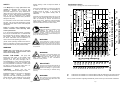
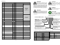
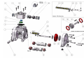
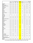
TECHNICAL DATA
Maximum Delivery:
26.5 Litres/min
Accessories Included:
Exhaust Air Silencer
Max. Working Pressure: 6.9 Bar (100 psi)
Shipping Weight:
1.4 Kg (3.0 Lb) - Poly.
2.0 Kg (4.5 Lb) - Kynar.
Max. Solid Particle Size: 1.5 mm (1/16”)
Shipping Dimensions:
160 mm x 230 mm x 120 mm
Air Inlet:
1/4” BSP(F)
Fluid Inlet/Outlet:
3/8” BSP(F)
Suction Lift (Dry):
3.05 M (10’)
Temperature Limits:
Polypropylene : Minimum
Maximum
Kynar : Minimum
Maximum
dB(A) Rating
0
0
0 C (32 F)
790C (1750F)
-120C (100F)
1070C (2250F)
Suction Lift (Wet):
6 M (20’)
78 dB(A)
FLUID
CONNECTIONS
CAPACITY
MAX
SOLIDS
MAX
DISCHARGE HEAD
DISPLACEMENT
/STROKE
3/8” BSP (F)
0 - 26.5 Liters/Minute
(0 - 5.8 Gallons/Minute)
1.5 mm
(1/16”)
70 Meters
(230 ft)
0.034 Litres
(0.007 Gallons U.K.)
NOTE! PUMP DISCHARGE IS
ON SAME SIDE AS EXHAUST
PREFERRED MOUNTING ARRANGEMENTS FOR PUMP.
INVERTED
AIR INLET
INVERTED OR SIDE MOUNTING
ENSURES 100% VENTING FOR
MAXIMUM PERFORMANCE.
SIDE
Installation Dimensions, All dimensions are +/- 1mm
LAMBERT ROAD,ARMSTRONG, WASHINGTON,
TYNE & WEAR NE37 1QP, ENGLAND.
TEL. : 0044 (0) 191 4177475
FAX. : 0044 (0) 191 4175435
Web Site : www.blagdonpump.com
E-Mail : [email protected]
A Unit of IDEX Corporation
B10
AIR OPERATED
DOUBLE DIAPHRAGM PUMP
OWNERS OPERATING &
SAFETY MANUAL
PRINCIPLE OF PUMP
OPERATION
opposite end of the centre body, the pressure
to the chambers is reversed.
The chambers are connected with rotatable
manifolds with a spring loaded suction and
discharge check valve for each chamber,
maintaining flow in one direction through the
pump.
This spring loaded check valve pump is
powered by compressed air and is a 1:1 ratio
design. The inner side of one diaphragm
chamber is alternately pressurised while
simultaneously exhausting the other inner
chamber. This causes the diaphragms, which
are connected by a common rod, to move in a
reciprocating action. (As one diaphragm
performs a discharge stroke the other
diaphragm is pulled to perform the suction
stroke in the opposite chamber.) Air pressure is
applied over the entire inner surface of the
diaphragm while liquid is discharged from the
opposite side of the diaphragm. The diaphragm
operates in a balanced condition during the
discharge stroke which allows the pump to be
operated at discharge heads of over 230 feet
(70 meters) of water.
INSTALLATION
Your installation will depend on the type of fluid
being pumped and your application needs. To
reduce the risk of serious bodily injury and
damage to property, never use fluids in this
pump which are not compatible with the wetted
components. Contact your local distributor or
the manufacturer for system design assistance
& compatibility if necessary.
The pump is fitted with spring loaded check
valves, as a result the pump can be mounted in
any position to suit the application needs.
Ensure the pump is securely mounted to avoid
movement and possible risk of bodily injury.
For maximum diaphragm life, keep the pump
as close to the liquid being pumped as
possible. Positive suction head in excess of 10
feet of liquid (3.048 meters) may require a back
pressure regulating device to maximize
diaphragm life.
PRESSURE The pump delivers the same
pressure at the discharge outlet as the air
pressure applied at the air inlet.
Alternate pressurising and exhausting of the
diaphragm chamber is performed by an
internally mounted, pilot operated, 2 way type
distribution valve. When the spool shifts to one
end of the centre body, inlet pressure is applied
to one chamber and the other diaphragm
chamber exhausts. When the spool shifts to the
NOTE: A Pressure Regulator should be
installed where air supply could exceed 100
psi.
HG-CF-1106 Rev. G 18.02.09
Page 8
Page 1
IMPORTANT!
This pump is pressurized internally with air
pressure during operation. Always make
certain that all bolting is in good condition
and that all of the correct bolting is reinstalled during
assembly.
CAUTION
Ensure that only the
recommended grade of lubricating oil is used.
BLAGDON PUMPS do not require any dedicated
lubrication system, however a periodical
application of an SAE 10 lubricating oil will help to
prolong seal life. Other grades of oil may cause
the Air Logic System to operate intermittently,
WARNING!
When used for toxic or aggressive fluids,
the pump should always be flushed clean
prior to disassembly.
Page 2
35
1
0.8
5
0
10
20
30
0
0
2
1.7
10
15
20
25
30
Capacity
in
Liters
Per
Minut
e
Capacity in Liters per Minute
20 psi
(1.4 bar)
40 psi
(2.8 bar)
5
60 psi
(4.1 bar)
3
5
4 4.2
6
7
8
2.5
3.3
5
5.8
6.7
Capacity
in
U.S
.
Gallons
P
er
Minut
e
Capacity in U.K. Gallons per Minute
9
7.5
CFM M3/HR
SCFM
1
1.7
3
5.1
5
8.5
40
FLUSH THE PUMP This pump was
tested with clean water. If this solution could
contaminate or react with the fluid you are
pumping, flush the pump thoroughly with a
solvent/detergent to clean internal components.
The solvent/detergent must be compatible with
the pump materials of construction. Care should
be taken to flush the pump each time it is
disassembled for maintenance or repair.
50
WARNING!
Take action to prevent static sparking. Fire
or explosion can result, especially when
handling flammable liquids. The pump,
piping, valves, containers or other miscellaneous
equipment must be grounded.
60
NEVER place your hands over or near the
pump suction inlet. Powerful suction could
cause serious bodily injury.
70
WARNING
80 psi
(5.5 bar)
(Under certain operating conditions the failure of
internal components can lead to the pumped fluid
being exhausted via the pump exhaust outlet).
3
WARNING!
Before maintenance or repair, shut off the
compressed air line, bleed the pressure,
and disconnect the air line from the pump.
The discharge line may be pressurized and must be bled
of its pressure.
80
If you are pumping hazardous fluids, or operating
the pump in an enclosed area, it is essential that
the exhaust from the pump is piped away to a
safe location. When pumping hazardous fluids
the above instructions must be adhered to in
order to ensure safe operating procedures.
90
Read these instructions completely, before
installation and start-up. It is the
responsibility of the purchaser to retain this
manual for reference. Failure to comply with the
recommendations stated in this manual will damage the
pump, and void factory warranty.
AIR CONSUMPTION IN CFM
IMPORTANT!
Failure to ensure 100% sealability of the
suction connection could adversely affect
suction performance.
100 1
To avoid leaks, ensure that all fluid connections
are tight. The use of PTFE thread tape correctly
applied should be used to ensure 100% leakproof
connections.
75 240
70
65 220
60 200
55 180
50 160
45
140
40
35 120
30 100
25
80
20
60
15
40
10
20
5
0
0
Meters Feet
Feet
If the fluid you are pumping tends to dry up or set
when it is not moving, then flush the pump as
often as necessary to prevent the fluid from
drying in the pump. Drain the pump thoroughly
before storing. If feasible, invert pump to allow
any fluid to drain from the non-return valves.
Displacement
Per Stroke,Per
0.007
Gal. (UK)
(0.034
Displacement
Stroke,
0.009
GalL) . (0.034 L)
If the pump accelerates or is running too fast due
to a lack of fluid, then stop it immediately by
shutting off the air supply. A dry pump will
accelerate to a high speed causing wear to
elastomers.
efficiencies.
However, as is common with
pneumatic equipment, the pump efficiencies is
reliant upon the air being clean, dry and filtered.
Failure to comply with these requirements may
lead to loss of performance and reduced
component life and in extreme cases, permanent
damage to the pump.
Recommended Operating Area
All figures based on pumping clean water at ambient temperature
100 psi
(7 bar)
Your B10 pump is a high performance unit
capable of achieving high outputs at high
Performance Curve
Discharge Head in PSI
thereby causing a loss of output and failure to
operate.
SAFETY
These items are available as a recommended Air Side Kit, ASK1001P, see page three for details.
These items are available as a recommended Wet Side Kit, see page three for Part Nos.
For any further information regarding available kits, please contact your local stockist / distributor.
Page 7
Parts List
Item
WARNING!
Description
Qty.
Standard: Polypropylene
CAUTION!
Before doing any maintenance on the
pump, be certain all pressure is completely
vented from the pump, suction, discharge,
piping, and all other openings and connections. Be
certain the air supply is locked out or made
non-operational, so that it cannot be started while work
is being done on the pump. Be certain that approved eye
protection and protective clothing are worn all times in
the vicinity of the pump. Failure to follow these
recommendations may result in serious injury or death.
1
Centre Section
1
E801A
2
Valve Gasket
1
E800J
3
Valve Insert
1
E500H
4
Air Diverter
1
10-075
5
End Cap
2
E800D
6
End Cap O-Ring
2
E500E
7
Valve Screw
4
10-050
8
Valve Body
1
10-048
9
Valve Spool
1
E500B
10
Valve Spool U-Cup
2
P98-104A
11
Main & Pilot Shaft O-Ring
8
E503B
12
Pilot Shaft Spacer
5
E503C
13
Shaft Retainer
2
E801B
14
Pilot Shaft
1
E803A
15
Pilot Shaft Snap Ring
2
E503D
16
Shaft Retainer Screw
4
E501C
POLY / SANTOPRENE PUMPS
KYNAR / PTFE PUMPS
17
Valve Seat
4
10-022(Poly)
10-039(Kynar)
18
Spring
4
10-030
10-030
WETTED COMPONENTS
10-038
P : POLYPROPYLENE
K : PVDF (KYNAR)
19
Valve Stem
4
20
Valve Seat Seal
8
10-005
AIR VALVE
ASSEMBLY
E800
(items 2 - 10)
WARNING!
Airborne particles and loud noise hazards.
Wear ear and eye protection.
WARNING!
In the event of diaphragm rupture, pumped
material may enter the air end of the
pump, and be discharged into the atmosphere. If pumping a product which is hazardous or toxic,
the air exhaust must be piped to an appropriate area for
safe disposition.
PILOT VALVE
ASSEMBLY
TYPICAL ORDER CODE =
RECYCLING
Many components of BLAGDON air
operated double diaphragm pumps are
made of recyclable materials. We
encourage pump users to recycle worn out parts and
pumps whenever possible, after any hazardous pumped
fluids are thoroughly flushed.
B10. 01. P P. R P P
VALVE SEATS
P : POLYPROPYLENE
K : PVDF (KYNAR)
MODEL - B10
10-073
10-045
Santoprene Option
PTFE Option
DESIGN LEVEL
VALVE STEMS
P : POLYPROPYLENE
K : PVDF (KYNAR
NON - WETTED COMPONENTS
21
Water Chamber Bolt (Short)
12
10-051
10-051
22
Water Chamber Bolt (Long)
4
10-052
10-052
23
Water Chamber
2
10-002
10-036
24
Foot Pad
4
10-035
10-035
25
Outer Diaphragm Plate
2
10-023(poly)
10-023(poly)
10-040(kynar)
10-040(kynar)
ITEM
SPARES KITS :- REFER TO TABLE & DRAWING ON PAGES 4,5 & 6
ASK1001P - AIR SIDE KIT
DESCRIPTION
QTY
PART NO.
DESCRIPTION
SA10RPP
POLY./SANTOPRENE
SA10TPP
POLY./PTFE
SA10RKK
KYNAR/SANT.
SA10TKK
KYNAR/PTFE
2
10-032(R)
10-044
2
VALVE GASKET
1
E800J
27
Inner Diaphragm Plate
2
C126
C126
3
VALVE INSERT
1
E500H
28
Main Shaft
1
10-028
10-028
4
AIR DIVERTER
1
10-075
Manifold
2
10-003
10-037
30
Muffler
1
06-034
06-034
WETTED END KITS
PART NUMBER
Diaphragm
29
DIAPHRAGMS
R : SANTOPRENE
T : PTFE
P : POLYPROPYLENE
26
Page 6
Before pump operation, inspect all
gasketed fasteners for looseness caused
by gasket creep. Re-torque loose
fasteners to prevent leakage. Follow recommended
torques stated in this manual.
6
END CAP O-RING
2
E500E
10
VALVE SPOOL U-CUP
2
P98-104A
11
PILOT SHAFT O-RING
6
E503B
11
MAIN SHAFT O-RING
2
E503B
Note. These descriptions refer to the Pump body
and Diaphragm materials.
Page 3
Page 4
Page 5