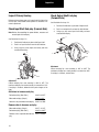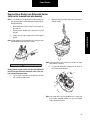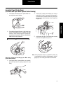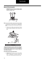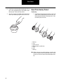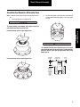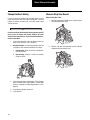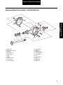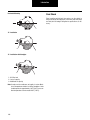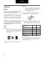
1
Spicer Tandem Drive Axles
®
Sevice Manual
Spicer® Tandem Drive Axles
AXSM-0042
September 2007
Models:
D/R440
D/R480
D/R461
D/R463
D/R581
D/R651
D/R653
D/R460
D/R485
D/R462
D/R521
D/R601
D/R652
Warning
Warnings and Caution
The description and specifications contained in this service
publication are current and the time of printing.
Dana Corporation reserves the right to discontinue or to modify its models and/or procedures and to change specifications
at any time without notice.
Any reference to brand names in this publication is made simply as an example of the types of tools and materials recommended for use and should not be considered an
endorsement. Equivalents, if available, may be used.
Important Notice
This symbol is used throughout this manual to call
attention to procedures where carelessness or failure
to follow specific instructions may result in personal
injury and/or component damage.
Departure from the instructions, choice of tools,
materials and recommended parts mentioned in this
publication may jeopardize the personal safety of the
service technician or vehicle operator.
WARNING
Failure to follow indicated procedures creates a high
risk of personal injury to the servicing technician.
CAUTION
Failure to follow indicated procedures may cause
component damage or malfunction.
IMPORTANT
Highly recommended procedures for proper service
of this unit.
NOTE: Additional service information not covered in
the service procedures.
TIP: Helpful removal and installation procedures to
aid in the service of this unit.
Always use genuine Dana replacement parts.
i
Table of Contents
Table of Contents - Visual
Wheel End
Page 99-101
Carrier Assembly
Page 45-56
Power Divider
Page 24-44
Table of Contents
Drive Pinion
Page 57-67
Wheel
Differential
Assembly
Page 68-82
Seals
Page 92-93
Differential
Lockout
Page 17-22
Ring Gear
Page 82-83
Differential
Carrier Assembly
Page 11-16
Wheel
Differential Lock
Page 83-90
Housing Breather
Page 94
Wheel End Seal
Page 95-96
Wheel Adjustment
Systems
Page 97-98
Housing and
Rear Cover
Assembly
Page 91
Lubrication
Page 102-106
Torque Chart
Page 107-108
ii
Table of Contents
Introduction .........................................................1
Failure Analysis ...................................................7
Inspection ...........................................................9
Differential Carrier Assembly - Parts .................11
Differential Lockout ...........................................17
Power Divider
Power Divider - Parts Exploded View........................ 23
Remove Power Divider ............................................. 24
Remove Power Divider from Differential Carrier
(with carrier removed from axle housing) ................ 25
Disassemble, Assemble and Overhaul
the Power Divider ..................................................... 27
Install Power Divider on Differential Carrier
(with carrier assembled to axle housing) .................. 38
Install Power Divider on Differential Carrier
(with carrier removed from axle housing) ................. 40
Dissasemble Differential Carrier
(with power divider removed) ................................... 54
Drive Pinion
Drive Pinion - Parts Exploded View ............................ 57
Disassemble and Overhaul Drive Pinion .................... 58
Install Drive Pinion Assembly.................................... 65
Wheel Differential Assembly
Wheel Differential Assembly
- Parts Exploded View ............................................... 68
Housing and Rear Cover Assembly
- Parts Exploded View ............................................... 91
iii
Seals ..................................................................92
Housing Breather ..............................................94
Wheel End Seal - Parts Exploded View .............95
Remove and Overhaul Wheel End Seal .............96
Wheel Adjustment Systems ..............................97
Verify Wheel End-play Procedure ......................99
Lubricate Wheel End .......................................100
Lubrication ......................................................102
Lube Change Intervals ....................................103
Change Lube ...................................................104
Standpipes ......................................................105
Torque Chart ...................................................107
Appendix
Wheel Differential Lock ...........................................109
Differential Lock Theory of Operation ....................110
Control Systems ....................................................111
Dual Range Axle Shift Systems ..............................113
Troubleshooting .....................................................120
Proper Vehicle Towing ...........................................122
Axle Shift System Components ..............................124
Inter-Axle Differential Lockout
With Interlock Control Valve (straight-air type) ......126
Theory of Operation ...............................................129
Power Flow and Torque Distribution ......................130
Lubrication .............................................................132
Torque Distribution in Low Range .........................136
General Information
Introduction
Dana Corporation, Axle & Brake Division, presents this publication to aid in maintenance and overhaul of Dana tandem
drive axles. Instructions contained cover the models listed.
Their design is common, with differences in load capacity. Capacity variations are achieved by combining basic differential
carrier assemblies with different axle housings, axle shafts and
wheel equipment.
Carrier Design and Identification
(DT440-P, DT460-P, DT480-P and DP440-P through DP650P)
On August 1, 1981, these axles were converted to a new configuration which includes redesign of the axle differential carrier; input shaft bearing, involute side gear and axle shaft spline
configuration. For carrier identification, see illustrations:
Input Shaft
Input shaft with Carrier Casting 110500 is equipped with a tapered roller bearing. Casting 103530 uses a ball bearing.
Input Shaft Bearing Spacer
Used only with Carrier Casting 110500.
Pinion Bearing Sleeve
Used only with Carrier Casting 103530.
Pinion Helical Gear Spacer
Used only on DT/DP440-P and DT/DP460-P (ratios 3.90-6.17).
Output Shaft Rear Bearing Retaining Washer
Used only on DT440-P - DT485-P and DP440-P - DP650-P.
Lube Pump Drive Shaft
The drive shaft on early pump design is equipped with a woodruff key. On late pump design, the key is eliminated. The drive
shaft end has two machined flats and the drive gear mounting
hole is shaped to accommodate these flats.
Axles built after August 1, 1981 with Carrier Casting No.
110500
Axles built before August 1, 1981 with Carrier Casting No.
103530
1
General Information
The suffix letter “P” in the model number indicates lube pump
is standard. Pump models are equipped with a gerotor pump,
designed to provide additional lubrication to the inter-axle differential and related parts.
Note: Refer to Dana Parts Book AXIP-0108 for parts information.
General Information
Model Listing
The following models are included in this publication:
Forward Axle
Rear Axle
DP440-P
DS440-P
Load Capacity
44,000 lbs.
RS440
DT440-P
DP460-P
DS460-P
46,000 lbs.
RS460
DT460-P
DD461-P
RD461
DP461-P
DS461-P
RS461
DT461-P
DP480-P
DS480-P
48,000 lbs.
RS480
DT480-P
DP485-P
DT485-P
DD521-P
RD521
52,000 lbs.
DP521-P
DS521-P
RS521
DT521-P
DP580-P
58,000 lbs.
DD581-P
RD581
DS581-P
RS581
DP581-P
DP601-P
60,000 lbs
DT601-P
DP650-P
DP651-P
DT461-P
DP652-P
2
65,000 lbs
The suffix letter "P" in the model number indicates the axle is
equipped with a lube pump which provides positive lubrication
in the inter-axle differential and other power divider parts.
Model variations and parts identification information is included throughout this manual. For more detailed parts information, refer to your Dana parts books.
General Information
Model Information
Lube Pump
P = Standard
(P) = Optional
S - Single Reduction
D - Single Reduction with Wheel
Differential Lock
T - Dual Range
P - Planetary Double Reduction
Design Level
General Information
Gearing
D - Forward Tandem Axle
R - Rear Tandem Axle
Capacity (x 1000 lbs.)
Example: 46 = 46,000 lbs.
Example: DS = Forward Tandem Axle/Single Reduction
RS = Rear Tandem Axle/Single Reduction
3
General Information
Model Identification
Drive Axle
Note: Tags that do not include all the information shown here
are older models (before May 1987).
4
3
5
Spicer®
CUST. PART NO.
SPEC.
SERIAL NO.
2
MODEL PART NO.
1
®recipS
.ON TRAP .TSUC
.ON LAIRES
OITAR
.CEPS
.ON TRAP LEDOM
:NI EDAM
Forward Axle (Side View)
6
RATIO
MADE IN:
7
Data plate is located on
the axle centerline
Spicer®
CUST. PART NO.
SPEC.
MODEL PART NO.
SERIAL NO.
RATIO
MADE IN:
Rear Axle (Top View)
1 - Country or origin
2 - Axle model identification
3 - Specification number assigned to the axle built by Spicer. Identifies all component parts of the axle including special OEM
requirements such as yokes or flanges.
4 - OEM part number assigned to the axle build
5 - Carrier assembly serial number assigned by the manufacturing plant
6 - Axle gear ratio
7 - Carrier assembly production or service part number
4
General Information
Part Identification
Axle Housing
Axle Shaft
2
®
erS.
Spic LB
.
NO
PT. CAP.
.
G.
HS I.D. NO DE IN
G.
HS ING MA
US
HO
General Information
1 - ID Tag
1
2 - Axle shaft part number
5
General Information
Ring Gear and Pinion
Note: Ring gear and drive pinion are matched parts and must
be replaced in sets.
3
8
38
127381
SPICER
OF
NL2
41-8
1
2
5
8
12
6
7
127
8-41
17
SPICER
0H
G
428
127
3
1
L7038
JD77
85405
6-39
86
4
1 - Part number
2 - Number of ring gear teeth
3 - Manufacturing numbers
4 - Matching gear set number
5 - Number of pinion teeth
6 - Date code
7 - Indicates genuine Spicer parts
8 - Heat code
6
L70
4
6
7
7
17
G
Failure Analysis
Failure Analysis
Failure analysis is the process of determining the original
cause of a component failure in order to keep it from happening again. Too often, when a failed component is replaced without determining its cause, there will be a recurring failure. If a
carrier housing is opened, revealing a ring gear with a broken
tooth, it is not enough to settle on the broken tooth as the
cause of the carrier failure. Other parts of the carrier must be
examined. For a thorough understanding of the failure and
possible insight into related problems, the technician needs to
observe the overall condition of the vehicle.
The true cause of a failure can be better determined by knowing what to look for, determining how a piece of the equipment
was running and learning about previous problems. In the case
of a rebuilt rear axle, mismatched gears may have been installed. The more successful shops prevent repeat equipment
failures by developing good failure analysis practices. Knowing
how to diagnose the cause of a premature failure is one of the
prerequisites of a good heavy-equipment technician.
The following five steps are an effective approach to good failure diagnostics.
1.
Document the problem.
2.
Make a preliminary investigation.
3.
Prepare the parts for inspection.
4.
Find the cause of the failure.
5.
Correct the cause of the problem.
Document the Problem
Here are some guidelines for starting to learn about a failure,
including questions to ask:
•
Talk to the operator of the truck.
•
Look at the service records.
•
Find out when the truck was last serviced.
•
Ask: In what type of service is the truck being used?
•
Ask: Has this particular failure occurred before?
•
Ask: How was the truck working prior to the failure?
You need to be a good listener. Sometimes, insignificant or unrelated symptoms can point to the cause of the failure.
•
Ask: Was the vehicle operating at normal temperatures?
•
Ask: Were the gauges showing normal ranges of operation?
•
Ask: Was there any unusual noise or vibration?
After listening, review the previous repair and maintenance
records. If there is more than one driver, talk to all of them and
compare their observations for consistency with the service
and maintenance records. Verify the chassis Vehicle Identification Number (VIN) number from the vehicle identification
plate, as well as the mileage and hours on the vehicle.
7
Failure Analysis
No one benefits when a failed component goes on the junk pile
with the cause unknown. Nothing is more disturbing to a customer than a repeat failure. Systematically analyzing a failure
to prevent a repeat occurrence assures quality service by
avoiding unnecessary downtime and further expense to the
customer.
How to Diagnose a Failure
Failure Analysis
Make a Preliminary Investigation
Find the Cause of the Failure
These steps consist of external inspections and observations
that will be valuable when combined with the results of the
parts examination.
Here begins the real challenge to determine the exact cause of
the failure. Keep in mind that there is no benefit to replacing a
failed part without determining the cause of the failure. For example, after examining a failed part and finding that the failure
is caused by a lack of lubrication, you must determine if there
was an external leak. Obviously, if there is an external leak, just
replacing the failed gear is not going to correct the situation.
•
Look for leaks, cracks or other damage that can point
to the cause of the failure.
•
Make note of obvious leaks around plugs and seals.
A missing fill or drain plug would be an obvious cause
for concern.
•
Look for cracks in the carrier housing (harder to see,
but sometimes visible).
•
Does the general mechanical condition of the vehicle
indicate proper maintenance or are there signs of neglect?
•
Are the tires in good condition and do the sizes
match?
•
If equipped with a torque-limiting device, is it working
properly?
During the preliminary investigation, write down anything out
of the ordinary for later reference. Items that appear insignificant now may take on more importance when the subassemblies are torn down.
Prepare the Parts for Inspection
After the preliminary investigation, locate the failure and prepare the part for examination. In carrier failure analysis, it may
be necessary to disassemble the unit.
8
•
When disassembling subassemblies and parts, do
not clean the parts immediately since cleaning may
destroy some of the evidence.
•
When tearing down the drive axle, do it in the recommended manner. Minimize any further damage to the
unit.
•
Ask more questions when examining the interior of
the carrier. Does the lubricant meet the manufacturer
specifications regarding quality, quantity and viscosity? As soon as you have located the failed part, take
time to analyze the data.
Another important consideration here is to determine the specific type of failure which can be a valuable indicator for the
cause of failure. The following pages show different types of
failures and possible causes. Use this as a guide in determining types of failures and in correcting problems.
Correct the Cause of the Problem
Once the cause of the problem has been determined, refer to
the appropriate service manual to perform the repairs.
Inspection
Inspection
Clean
1.
Wash steel parts with ground or polished surfaces in
solvent. There are many suitable commercial solvents available. Kerosene and diesel fuel are acceptable.
Note: Replace conventional gaskets with silicone rubber gasket compound (included in many repair kits). The compound provides a more effective seal against lube
seepage and is easier to remove from mating surfaces
when replacing parts.
WARNING
1
Gasoline is not an acceptable solvent because of its extreme
combustibility. It is unsafe in the workshop environment.
Inspection
2.
Wash castings or other rough parts in solvent or
clean in hot solution tanks using mild alkali solutions.
Note: If a hot solution tank is used, make sure parts are heated
thoroughly before rinsing.
3.
Rinse thoroughly to remove all traces of the cleaning
solution.
4.
Dry parts immediately with clean rags.
5.
Oil parts.
•
If parts are to be reused immediately: Lightly oil.
•
If parts are to be stored: Coat with oil, wrap in
corrosion resistant paper and store in a clean,
dry place.
Inspect Axle Housing
Axle housing inspection and repairs are limited to the following
checks or repairs:
•
Visually inspect axle housing for cracks, nicks and
burrs on machined surfaces.
•
Check carrier bolt holes and studs for foreign material.
•
Replace damaged fasteners. Look for loose studs or
cross threaded holes.
CAUTION
Any damage which affects the alignment or structural integrity of the housing requires housing replacement. Do not repair by bending or straightening . This process can affect
the material's properties and cause it to fail completely under load.
•
Check all seals and gaskets.
2
1 - Axle housing
2 - Machined surface
Inspect Components
Inspect all steel parts for:
•
Notches, visible steps or grooves created by wear
•
Pitting or cracking along gear contact lines
•
Scuffing, deformation or discolorations. These are
signs of excessive heat in the axle and are usually related to low lubrication levels or improper lubrication
practices.
In addition, inspect the following for damage:
•
Differential gearing
•
Bearings for loose fit on drive pinion, pilot bearing,
and differential bearings
•
All fasteners for rounded heads, bends, cracks or
damaged threads.
•
Inspect machined surfaces of cast or malleable parts.
They must be free of nicks, burrs, cracks, scoring,
and wear.
•
Look for elongation of drilled holes, wear on surfaces
machined for bearing fits and nicks or burrs in mating
surfaces.
9
Inspection
Inspect Primary Gearing
Before reusing a primary gear set, inspect teeth for signs of excessive wear. Check tooth contact pattern for evidence of incorrect adjustment.
Check Output Shaft End-play
(Forward Axle)
See illustration for steps 1-3.
Check Input Shaft End-play (Forward Axle)
Note: Before disassembling the power divider, measure and
record input shaft end-play.
1.
Position dial indicator at yoke end of output shaft.
2.
Push in on output shaft and zero the dial indicator.
3.
Using a pry bar, move input shaft axially and measure/record end-play.
3
See illustration for steps 1-3.
1.
Position dial indicator at yoke end of input shaft.
2.
Push in on input shaft and zero the dial indicator.
3.
Using a pry bar, move input shaft axially and measure/record end-play.
3
2
1
Adjustment
Correct end-play for a new assembly is .001" to .005". The
maximum end-play for a used assembly is no more than .005".
If end-play is incorrect, contact Dana.
2
1
Adjustment
Correct end-play for a new assembly is .003" to .007". The
maximum end-play for a used assembly is no more than .014".
If end-play is incorrect, determine shim pack changes as follows:
Add shims to increase end-play
Desired end-play (New Parts)
0.003" to 0.007"
Measured end-play (Step 3)
0.001”-0.001”
Add shims to provide desired end-play
0.002" to 0.006"
Remove shim to decrease end-play
Measured end-play (Step 3)
0.015" – 0.015"
Desired end-play (New Parts)
0.003” to 0.007”
Remove shims to provide desired end- 0.012” to 0.008”
play
10
Differential Carrier Assembly
Differential Carrier Assembly - Parts
5
1
2
3
Differential Carrier
Assembly
4
1 - Carrier fasteners
2 - Carrier assembly
3 - Forward axle assembly
4 - Inter-axle differential lockout
5 - Rear axle assembly
11
Differential Carrier Assembly
Forward Axle Differential Carrier Removal and Installation
Removal of Forward Differential Carrier
Note: The removal of the forward carrier requires disconnecting of the inter-axle driveline and removal of the output
shaft yoke assembly.
1.
Block the vehicle.
2.
Drain axle lubricant.
3.
Disconnect all air lines to the axle.
4.
Disconnect inter-axle and main drivelines.
5.
Remove axle stud nuts and axle shafts (If used, remove lock washers and taper dowels).
6.
Remove carrier capscrews, nuts and lock washers.
7.
Forward Models Only: Remove output shaft shoulder nut and yoke.
8.
Remove differential carrier assembly.
Removal of Forward Axle Housing Cover
Tip: The bearing parts can be serviced separately
without removing the housing cover form the axle
housing
WARNING
The differential lock 461/521/581 models use axle shafts
with different spline length (4" or 11"). Axle shafts may also
be location specific with various wheel equipment. Do not
misplace axle shafts from their intended location.
TIP: To loosen dowels, hold a brass drift in the center of the
shaft head and strike drift with a sharp blow using a hammer.
Do not lie under carrier after fasteners are removed. Use
transmission jack to support differential carrier assembly
prior to loosening fasteners.
1.
Block the vehicle.
2.
Drain axle lubricant.
3.
Disconnect inter-axle driveline.
4.
Remove output shaft shoulder nut and yoke.
5.
Remove capscrews, nuts, and lock washers fastening cover to axle housing.
6.
Remove oil seal and discard.
7.
Remove bearing retaining washer, if used.
8.
If replacement is necessary, remove snap ring, bearing and bearing sleeve.
WARNING
CAUTION
Snap ring is spring steel and may pop off. Wear safety glasses when removing.
Do not strike the shaft head with a steel hammer. Do not use
chisels or wedges to loosen shaft or dowels.
1
2
3
4
5
6
7
1 - Carrier fasteners
2 - Carrier assembly
3 - Forward axle assembly
4 - Axle shaft
12
5 - Nut
6 - Lock washer
7 - Lift and support
Inspection
Installation of Forward Differential Carrier
IMPORTANT
Before installing carrier assembly, inspect and thoroughly
clean interior of axle housing using an appropriate solvent
and clean rag.
1.
Use silicone rubber gasket compound on axle housing mating surface as shown in the illustration. Completely remove all old gasket material prior to
applying new material. Compound will set in 20 minutes. Install carrier before compound sets or reapply.
2.
Install differential carrier assembly to axle housing
using lockwashers, capscrews and nuts. Torque to
proper specification (see Torque Chart on page 107).
3.
With the forward axle now assembled to the housing,
proceed with Installation of Forward Axle Housing
Cover and Output Shaft Bearing Parts, on next page.
4.
Install output yoke and self-locking nut. Tighten to
specified torque (see Torque Chart on page 107).
Reference Yoke Installation Section page 92.
5.
Install axle shafts and axle stud nuts (If used, also install lock washers and taper dowels).
WARNING
The differential lock 461/521/581 models use axle shafts
with different spline length (4" or 11"). Axle shafts may also
be location specific with various wheel equipment. Do not
misplace axle shafts from their intended location.
6.
Connect main and inter-axle driveline. Ensure drivelines are properly phased. Lubricate U-joints.
7.
Add axle lubricant. See Lube Fill Capacities on page
104 for correct amount.
When axle has been disassembled
or housing, axle shafts or wheel equipment re
placed, check axle assembly for proper differential action before operating vehicle. Wheels must
rotate freely and independently.
Road test vehicle to bring axle lubricant up to temperature. Recheck joints, drain and fill plugs for leakage. Re-tighten as necessary.
Differential Carrier Side of Axle Housing
2
1
Axle Housing Silicone Gasket Compound Pattern
1 - Apply silicone gasket in this pattern
2 - Typical stud locations
Note: Oil fill plug removed from D461/462/463 Differential
Carriers. The oil fill plug hole located in the differential
carrier was removed. Lube capacity is not affected, customers to fill axle with lube through rear cover fill hole or
through the breather hole in housing. February 1, 2000.
8.
Connect air lines to differential.
13
Inspection
TIP: To assist in installing complete differential carrier, use two pieces of threaded rod (5/8"- 11 UNS)
threaded into carrier capscrew holes. Rod should be
approximately 6" long. Use these to pilot the carrier
into the housing.
IMPORTANT
Differential Carrier Assembly
Installation of Forward Axle Housing Cover
and Output Shaft Bearing Parts
Note: Forward axle should be assembled to the axle housing
before proceeding with the following procedure.
1.
If removed, install housing cover and fasten with
nuts, capscrews and lock washers. Tighten to proper
torque specifications (see Torque Chart on page
107).
Note: Use silicone rubber gasket compound on axle housing
mating surface as shown in illustration. Completely remove all old gasket material prior to applying new material. Compound will set in 20 minutes. Install axle
housing cover and output shaft assembly before compound sets or reapply.
2.
Install output shaft rear bearing. Tap the outer race
(with a sleeve or brass drift) until it is seated firmly in
the machined pocket of the cover. Secure with snap
ring.
3.
Lubricate and install the rear bearing sleeve on the
output shaft. Make certain it fits snugly against the
shoulder at the forward edge of the shaft splines.
4.
Install the output shaft seal in the axle housing cover.
IMPORTANT
When axle has been disassembled or housing, axle shafts or
wheel equipment replaced, check axle assembly for proper
differential action before operating vehicle. Wheels must rotate freely and independently.
Road test vehicle to bring axle lubricant up to temperature. Recheck joints, drain and fill plugs for leakage. Re-tighten as necessary.
Cover Side of Axle Housing
2
2
Note: Some axles require the use of a rear bearing retaining
washer. Install the washer over the splines of the output
shaft flush against the output shaft bearing.
5.
6.
Install output yoke and self-locking nut. Tighten to
specified torque (see Torque Chart on page 107).
Reference Yoke Installation Section page 92.
Install axle shafts and axle stud nuts (If used, also install lock washers and taper dowels).
WARNING
The differential lock 461/521/581 models use axle shafts
with different spline length (4" or 11"). Axle shafts may also
be location specific with various wheel equipment. Do not
misplace axle shafts from their intended location.
7.
Connect main and inter-axle driveline. Ensure drivelines are properly phased. Lubricate U-joints.
8.
Add axle lubricant. See Lube Fill Capactities on page
104 for correct amount.
Note: Oil fill plug removed from D461/462/463 Differential
Carriers. The oil fill plug hole located in the differential
carrier was removed. Lube capacity is not affected, customers to fill axle with lube through rear cover fill hole or
through the breather hole in housing. February 1, 2000.
9.
14
Connect air lines to differential.
2
1 - Apply silicone gasket in this pattern
2 - Stud locations (varies by model)
1
2
Differential Carrier Assembly
Rear Axle Differential Carrier Removal and Installation
Removal of Rear Differential Carrier
Perform the following steps:
TIP: To loosen dowels, hold a brass drift in the center of the
shaft head and strike drift with a sharp blow using a hammer.
1.
Block the vehicle.
2.
Drain axle lubricant.
3.
Disconnect air line if working on a differential lock axle. (See Differential Lockout Section).
Disconnect inter-axle driveline.
5.
Remove axle stud nuts and axle shafts (If used, remove lock washers and taper dowels).
CAUTION
Do not strike the shaft head with a steel hammer. Do not use
chisels or wedges to loosen shaft or dowels.
WARNING
6.
Remove capscrews, nuts and lock washers.
7.
Remove differential carrier assembly.
The differential lock 461/521/581 models use axle shafts
with different spline length (4" or 11"). Axle shafts may also
be location specific with various wheel equipment. Do not
misplace axle shafts from their intended location.
1
2
3
4
5
6
1 - Carrier fasteners
2 - Carrier assembly
3 - Rear axle assembly
4 - Axle shaft
5 - Nut
6 - Lock washer
15
Differential Carrier
Assembly
4.
Do not lie under carrier after fasteners are removed. Use
transmission jack to support differential carrier assembly
prior to loosening fasteners.
Differential Carrier Assembly
Rear Differential Carrier “Installation”
IMPORTANT
Before installing carrier assembly, inspect and thoroughly
clean interior of axle housing using an appropriate solvent
and clean rag.
Road test vehicle to bring axle lubricant up to temperature. Recheck joints, drain and fill plugs for leakage. Re-tighten as necessary.
Note:
Note:
Note: Apply silicone rubber gasket compound on axle housing
mating surface as shown in illustration. Completely remove all old gasket material prior to applying new material. Compound will set in 20 minutes. Install carrier
before compound sets or reapply.
1.
Install differential carrier assembly.
TIP: To assist in installing complete differential carrier use two pieces of threaded rod (5/8"- 11 UNS)
threaded into carrier capscrew holes. Rod should be
approximately 6" long. Use these to pilot the carrier
into the housing.
2.
Install carrier to axle housing lock washers, capscrews and nuts. Torque to proper specification. See
“Torque Chart” on page 107.
3.
Install axle shafts and axle stud nuts (If used, also install lock washers and taper dowels).
WARNING
The differential lock 461/521/581 models use axle shafts
with different spline length (4" or 11"). Axle shafts may also
be location specific with various wheel equipment. Do not
misplace axle shafts from their intended location.
4.
Connect inter-axle driveline, making sure driveline is
in phase. Lubricate U-joints.
5.
Add axle lubricant. Fill to bottom of filler hole. See
“Change Lube” on page 104. Reference Lube Fill Capacities for correct amount.
6.
Connect air line to differential if working on a differential lock model axle.
IMPORTANT
When axle has been disassembled or housing axle shafts or
wheel equipment replaced, check axle assembly Afor proper
differential action before operating vehicle. Wheels must rotate freely and independently.
16
2
1
1 - Apply silicone gasket in this pattern
2 - Typical stud locations
Differential Lockout
Differential Lockout
Inter-Axle Lockout Types
All are air-operated to engage the lockout and spring-released
to disengage the lockout with the exception of the “ReverseAir” lockout. The “Reverse-Air” lockout is spring-released to
engage the lockout and air-operated to disengage the lockout.
2
•
External type lockout
•
Cast iron piston cover
3
4
5
6
Differential Lockout
1
Cast Iron Cover Lockout - February 1996 to
Present (Single Reduction Models)
7
8
1 - Shift fork assembly
2 - Compression spring
3 - Piston driver
4 - O-ring
5 - Piston
6 - Lock nut
7 - Cast iron piston housing
8 - Capscrew
17
Differential Lockout
Original Design Lockout - 1948 to Present
(*Optional design for use with all dual
range tandem axles)
•
Die cast body
•
Square Top
•
Interchangeable with cast iron lockout*
“In 1985, a “Protective Shift System” was released into production axles. Dana bulletin 85-03 explains this popular OEM
option. This option can only work with the “original” design
lockouts.
7
4
5
1
6
13
14
8
15
16 17
2
1 - Shift fork assembly
2 - Push rod o-ring
3 - Body o-ring
4 - Lock washer
5 - Cap screw
6 - Original design lockout body
7 - Piston o-ring
8 - Piston
18
3
Original
design
10
12
11
9
9 - Felt oilers
10 - O-ring
11 - Flat washer
12 - Lock nut
13 - Compression spring
14 - Cover o-ring
15 - Cover
16 - Lock washer
17 - Capscrew
Differential Lockout
Cylindrical Design Lockout - October 1989
to February 1996
•
•
Stamped steel piston cover
•
Interchangeable with the cast style cover only as a
complete assembly
External type lockout
4
1 - Shift fork assembly
2 - Shoulder washer
3 - Compression spring
4 - O-ring
5 - Piston
2
3
6
10
Differential Lockout
1
8 9
5
7
6 - Lock nut
7 - Cylindrical design piston housing
8 - Mounting bracket
9 - Lock washer
10 - Capscrew
19
Differential Lockout
Differential Lockout Overhaul
Instructions for the three different designs are on the following
pages:
Assemble and Install Lockout - Cast Iron
Cover Design
Cast Iron Cover Lockout - Overhaul on page 20
1.
With shift fork and sliding clutch installed, install
compression spring on push rod.
2.
Place piston driver on push rod against compression
spring. The large diameter end of piston driver must
face power divider cover.
3.
Lubricate o-ring with silicone-based lubricant and install o-ring on piston.
4.
Place piston assembly on push rod against piston
driver.
5.
Install lock nut on push rod and tighten to 13-17 lbs.
ft. (18-23 N•m).
6.
Apply silicone gasket compound to mounting surface
on power divider cover.
Original Design Lockout - Overhaul on page 21
Cylindrical Design Lockout - Overhaul on page 22
Cast Iron Cover Lockout - Overhaul
Disassemble and Remove Lockout
Note: With axle installed in vehicle, place differential lock selector valve in the disengaged (or unlocked) position.
Disconnect the air line at the lockout piston cover.
1.
Remove capscrews and lock washers fastening piston housing to power divider cover. Remove the cast
iron piston housing.
2.
Remove lock nut, piston with o-ring, piston driver
and compression spring from push rod.
Note: The shift fork and push rod cannot be removed with
power divider cover installed (see Remove Power Divider on
page 24).
1
Lockout Interchangeability
The cast iron design lockout assembly is interchangeable with
previously designed lockouts, only as a complete assembly.
The original shift fork and push rod can be used for all three
design type lockouts and need not be replaced.
Retrofit kits are available to convert the non-current design
lockouts to the current cast iron cover design lockout. For additional information, refer to Dana Parts Books AXIP-0085.
Retrofit as follows:
1.
Disassemble and remove the old design lockout.
2.
Assemble and install the cast iron cover lock-out.
CAUTION
Mounting screws are not interchangeable between the various design style lockouts. They are a different length and
size.
20
1 - Lockout silicone gasket pattern
7.
Install piston housing cover.
8.
Install capscrews and tighten to 48-56 lbs. ft.
(65-76 N•m).
9.
If axle is installed in vehicle, apply sealant to air line
fitting and connect air line.
Differential Lockout
Original Design Lockout Overhaul
Note: Find instructions for:
Cast Iron Cover Lockout - Overhaul on page 20
Cylindrical Design Lockout - Overhaul on page 22
Assemble and Install Original Design Lockout
With shift fork and sliding clutch installed in power divider cover, assemble and install lockout as follows:
Disassemble and Remove Lockout
1.
1.
Remove capscrews and lock washers fastening cover to the body. Remove cover and o-ring.
2.
Remove nut, flat washer and o-ring from push rod.
3.
Remove body capscrews and lock washers, then remove body and piston as an assembly. Remove oring and felt oilers from the piston.
Differential Lockout
Note: With axle installed in vehicle, place differential lock selector valve in the disengaged (or unlocked) position.
Disconnect the air line at the lockout piston cover.
Apply silicone gasket compound to mounting surface
on power divider cover.
1
Note: The shift fork and push rod cannot be removed with
power divider cover installed (see Remove Power Divider on
page 24).
Retrofit Original Design to Cast Iron Cover
Design Lockout
The cast iron cover design lockout assembly is interchangeable with the original design lockout, only as a complete assembly. The original shift fork and push rod can be used for
either model lockout and need not be replaced.
Retrofit kits are available to convert the non-current design
lockouts to the current cast iron cover design lockout. For additional information, refer to Dana Parts Books AXIP-0085.
Retrofit as follows:
1.
Disassemble and remove the original design lockout.
2.
Assemble and install the cast iron cover lockout.
CAUTION
1 - Lockout silicone gasket pattern
2.
Install lockout body. Secure with capscrews and lock
washers. Torque capscrews to 48-56 lbs. ft.
(65-76 N•m).
Note: Before installation, soak piston felt oilers in SAE 30 engine oil and lubricate o-rings with a high-viscosity silicone oil or barium grease o-ring lubricant.
3.
Install felt oilers and large o-ring on piston.
4.
Install compression spring over shift fork push rod.
Install piston over end of shift fork into lockout body.
Secure with lock washers and lock nut. Torque locknut (see Torque Chart on page 107).
5.
Install o-ring in lockout body cover. Install cover and
secure with capscrews and lock washers. Torque
capscrews to 96-108 lbs. in. (10-13 N•m).
Mounting screws are not interchangeable between the various design style lockouts. They are a different length and
size.
21
Differential Lockout
Cylindrical Design Lockout - Overhaul
Note: Find instructions for:
Cast Iron Cover Lockout - Overhaul on page 20
Original Design Lockout - Overhaul on page 21
Assemble and Install Lockout-Cylindrical
Design
1.
With shift fork and sliding clutch installed, place the
shoulder washer (white plastic) over push rod. The
large diameter side of the washer must face the power divider cover.
2.
Install compression spring on push rod.
3.
Lubricate o-ring with silicone-based lubricant and install o-ring on piston.
4.
Place piston assembly on push rod. The large diameter end of piston must face power divider cover.
5.
Install lock nut on push rod and tighten to 13-17 lbs.
ft. (18-23 N•m).
6.
Install piston housing, making sure the housing is
correctly seated and piloted in the shoulder washer.
Disassemble and Remove Lockout
Note: With axle installed in vehicle, place differential lock selector valve in the disengaged (or unlocked) position.
Disconnect the air line at the lockout piston cover.
1.
Remove capscrews and lock washers fastening
mounting bracket to power divider cover. Remove
bracket and piston housing.
2.
Remove lock nut, piston with o-ring, compression
spring and shoulder washer from push rod.
Note: The shift fork and push rod cannot be removed with
power divider cover installed (see Remove Power Divider
on page 24).
Retrofit Cylindrical Design to Cast Iron
Cover Design Lockout
The cast iron cover design lockout assembly is interchangeable with the cylindrical design lockout, only as a complete assembly. The original shift fork and push rod can be used for
either type lockout and need not be replaced.
Retrofit kits are available to convert the non-current design
lockouts to the current cast iron cover design lockout. For additional information, refer to Dana Parts Books AXIP-0085.
Retrofit as follows:
1.
Disassemble and remove the cylindrical design lockout.
2.
Assemble and install the cast iron cover lockout.
CAUTION
Mounting screws are not interchangeable between various
design style lockouts. They are a different length and size.
22
1
1 - Shoulder washer must seat properly
7.
Place mounting bracket over housing and position on
power divider cover. Install capscrews and lock
washers and tighten to 48-56 lbs. ft. (65-76 N•m)
Note: If axle is installed in vehicle, apply sealant to air line fitting and connect air line. When tightening air line, hold
piston housing in mounting position using a wrench applied to the hexagon configuration at outer end of housing.
Inspection
Power Divider - Parts Exploded View
12
11
1
2* 3
4
5
6
7
8
9
13
10
18
19
21 22 23
24
25
27
28 29 31
32 33
36
37 38
34
20
30
26
40
39
1 - Output shaft
2 - Bushings*
3 - O-rings
4 - Bearing cup
5 - Bearing cone
6 - Side gear
7 - Snap ring
8 - Spring
9 - Button
10 - Inter-axle differential assembly
11 - Capscrew
12 - Case half
13 - Spider
14 - Nut
* Removed in September 1994
35
15 14
Inspection
17 16
15 - Case half
16 - Side pinion
17 - Thrust washer
18 - Snap ring
19 - Helical gear
20 - Bushings
21 - Thrust washer
22 - “D” washer
23 - Lockout sliding clutch
24 - Input shaft
25 - Bearing cone
25 - Shift fork and push rod
27 - Power divider cover
28 - Lock washer
29 - Capscrew
41
42
44
43
30 - Lockout unit
31 - Bearing cup
32 - Shim
33 - Bearing cover
34 - Capscrew
35 - Oil seal
36 - Yoke
37 - Flat washer
38 - Nut
45
47 48
46
49
Lube Pump Parts
39 - Lock nut
40 - Pump drive gear
41 - Expansion plug
42 - Pipe plug
43 - Magnetic screen
44 - Pump gears
45 - O-ring
46 - Dowel pin
47 - Pump cover
48 - Lock washer
49 - Capscrew
23
Power Divider
Remove Power Divider
The power divider can be replaced with the axle assembly both
in or out of the chassis and with the differential carrier assembled to the axle housing.
CAUTION
During removal of power divider cover, the inter-axle differential (IAD), input shaft assembly or IAD shift system parts
may fall from the carrier if not careful. Use caution to prevent injury or damage.
1.
Disconnect the main driveline.
2.
Disconnect the lockout air line.
3.
If overhauling the power divider, loosen but do not remove input nut.
4.
Position a drain pan under the unit.
5.
Remove PDU capscrews.
Method A - With Carrier Installed in
Chassis
1.
Use a transmission jack or a chain hoist and a sling.
2.
Wrap sling strap around power divider and attach to
chain hoist hook.
3.
Tap on the sides of the cover at the dowel pins with a
mallet to create a space large enough to finish freeing
the cover from the dowel pins.
4.
Pull the power divider forward until the input shaft
stub end is free of the output side gear, then remove
the assembly.
5.
24
Remove IAD assembly.
Method B - With Carrier Out of Chassis
1.
Use a chain hoist.
2.
Mount carrier assembly in carrier assembly stand.
3.
Remove PDU capscrews.
4.
Fasten chain or strap to input yoke to remove power
divider.
CAUTION
During removal of power divider cover, the inter-axle differential (IAD), input shaft assembly or IAD shift system parts
may fall from the carrier if not careful. Use caution to prevent injury or damage.
Note: Lifting mechanism may create nicks and burrs on input
yoke. Remove nicks and burrs if present.
5.
Tap the sides of the cover at the dowel pin location
with a mallet to loosen cover.
6.
Remove PDU assembly.
7.
Remove IAD assembly.
1
1 - Carrier assembly stand
Power Divider
Remove Power Divider from Differential Carrier
(with carrier removed from axle housing)
Note: It is assumed that the differential carrier assembly has
been removed from axle housing prior to starting the following procedures:
Mount differential carrier in repair stand. Loosen input shaft nut.
2.
Remove power divider cover capscrews and lock
washers.
3.
Fasten chain or strap to input yoke to remove power
divider.
With chain hoist attached to input yoke, lift power divider off carrier.
Power Divider
1.
5.
Note: Power divider may not separate easily, strike the cover
near the dowel pin location with a mallet.
CAUTION
Note: Lifting mechanism may create nicks or burrs on input
yoke. Remove if present.
6.
During removal of power divider, the inter-axle differential
may fall off input shaft from differential carrier. Exert caution to prevent damage of injury.
4.
Lift inter-axle differential assembly out of carrier or
off of output shaft side gear.
Tap the sides of the cover at the dowel pin location
with a mallet to loosen cover.
Note: Late model axles may be equipped with a spring and
thrust button mounted between the input and output
shafts, remove these parts.
25
Power Divider
26
7.
Tilt carrier and remove the output shaft assembly.
8.
If removal of the output shaft side gear bearing cup is
necessary, use puller to remove bearing cup from
carrier
Power Divider
Disassemble, Assemble and Overhaul the Power Divider
The power divider may be serviced with the carrier assembly
in or out of the axle housing.
Hammer: Use slipper to get under the cup and with a
hammer and drift from the back side of carrier tap out
bearing cup.
Note: The following procedure assumes that the differential
carrier has been removed from the axle housing and that
the power divider has been removed from the carrier assembly.
Late model axles may be equipped with a spring and
thrust button mounted between the input and output
shafts, remove these parts.
2.
Remove output shaft and output side gear
3.
Power Divider
1.
4.
Remove snap ring from machined groove at rear of
input shaft.
5.
Slide helical side gear off input shaft.
6.
Remove helical side gear thrust washer, and “D”
washer from shaft.
If replacement of the output shaft side gear bearing
cup is necessary, use either of the following methods:
Weld: Place a weld bead around the inside of the cup,
when the weld cools the cup will fall out.
27
Power Divider
7.
At this point in disassembly, it is desirable to remove
lube pump drive gear nut. Hold input shaft yoke to secure drive gear, then loosen and remove drive gear
nut.
8.
Remove input shaft nut and flat washer.
Note: Shift fork cannot be removed until lockout unit is disassembled (see Differential Lockout Overhaul on page 20).
Shift fork push rod is secured to the lockout piston with
a nut.
12. Slide input shaft assembly out of cover.
Note: Some models do not use flat washer as it is built into the
nut.
9.
Remove yoke from input shaft using a puller tool.
TIP: A yoke puller tool may be made from the center
section of most gear puller tools, or may be purchased from your local tool distributor.
10. Remove input bearing cage, capscrews, input bearing cover and shim pack.
13. Remove sliding clutch.
11. If input shaft bearing cup needs replacement, use either of the following recommended practices:
Weld: Place a weld bead around the cup, when the
weld cools the cup will fall out.
Drill: Drill a 1/4 inch size hole through the bearing
cover to the back side of the cup and use a punch to
remove the bearing cup.
28
1
1 - Sliding clutch
14. Remove input shaft bearing cone. Temporarily place
lockout sliding clutch over rear of input shaft, teeth
toward bearing cone. Place shaft in press and remove.
Power Divider
Disassemble Power Divider Cover
(For Axles with Input Shaft Tapered Roller Bearing)
Note: The drive on early pump models is equipped with a woodruff key. On late pump models the key is eliminated. The
drive shaft end has two machined flats and the drive gear
mounting hole is shaped to accommodate these flats.
2
1
4*
5
13
Power Divider
3
6
12
7
11
10
9
8
1 - Lock nut
2 - Power divider cover
3 - Pipe plug
4 - Woodruff key
5 - O-ring
6 - Pump cover
7 - Capscrew
8 - Lock washer
9 - Dowel pin
10 - Pump gears
11 - Magnetic strainer
12 - Expansion plug
13 - Pump drive gear
29
Power Divider
1.
With drive gear locknut previously removed and
working through input shaft bore, gently pry oil pump
drive gear from its shaft. See steps 5 and 6 for pump
disassembly.
2.
For models built before February 1, 2000, remove
snap ring securing pinion outer support bearing race.
For models built after February 1, 2000, a design
change to a one piece roller bearing was implemented. Reference Dana Bulletin ABIB-0102 for more information.
4.
Unscrew and remove magnetic strainer from power
divider cover.
5.
Remove oil pump cover capscrews and lock washers. Remove pump cover and o-ring.
6.
When woodruff key is used, remove key from gear
shaft. Remove pump gears from power divider cover.
WARNING
Snap ring is spring steel and may pop out. Wear safety
glasses when removing.
3.
30
Remove pinion outer support bearing race with suitable puller.
Power Divider
Assemble Power Divider Cover
(For Axles with Input Shaft Tapered Roller Bearing)
Install pinion outer bearing race in power divider cover using a driver and a hammer.
2.
For models built before February 1, 2000, install snap
ring to secure bearing race. For models built after
February 1, 2000, a design change to a one piece roller bearing was implemented. Reference Dana Bulletin
ABIB-0102 for more information.
WARNING
Snap ring is spring steel and may pop out. Wear safety
glasses when installing.
3.
4.
Install o-ring in pump cover, making sure o-ring is
seated firmly in body. If removed, install dowel pins.
Install pump cover on power divider cover and secure
with capscrews and lock washers. (See Torque Chart
on page 107).
5.
Install pump drive gear. Install drive gear on pump
shaft end. Hand tighten drive gear nut.
Power Divider
1.
Note: Some pump drive shafts use a woodruff key. When key
is used, place key in shaft slot. Position gear on shaft engaging key. Then install gear with driver and hammer.
Install pump gears in power divider cover (position
gear with long shaft in opening adjacent to input
shaft).
31
Power Divider
6.
Press input bearing cone on input shaft.
8.
If bushing removal is needed, the bushings must exit
from the thrust washer side of the helical gear.
1
1
2
3
4
1 - Remove bearing from helical gear
9.
1 - Press
2 - Plate
3 - Drive Seal
4 - Input shaft bearing cone
5 - Input shaft
5
Install bushings in helical side gear. Bushings must
be installed from thrust washer side of gear. See illustration for dimensional tolerances.
Note: Starting in March 1995, helical side gears are designed
with a shoulder step that helps prevent bushing walkout.
The inner bushing must be installed from the thrust
washer side of the helical gear against the shoulder step.
1 - Press
2 - Plate
3 - Drive sleeve
4 - Input shaft bearing cone
5 - Input shaft
7.
1
1 - Step added
Press bearing cup in input bearing cover.
1
1
2
5
3
6
1/32"
4
1
1 - Input bearing cage
32
1 - Press
2 - Sleeve
3 - First bushing (press to shoulder step)
4 - Shoulder
5 - Sleeve
6 - Second bushing (recess 1/32”)
Power Divider
10. Check expansion plug in power divider cover to make
sure it is in place and firmly seated. If loose, seat by
tapping with a hammer. Replace plug if necessary.
Snap ring is spring steel and may pop off. Wear safety glasses when installing.
Power Divider
1
1 - Expansions plug
11. Install shift fork in power divider cover.
12. Install lockout cylinder assembly if removed. See Differential Lockout on page 20.
13. Place sliding clutch in power divider cover, engaging
clutch with shift fork. Position clutch teeth toward helical side gear.
14. Slide input shaft into power divider cover. Engage
shaft splines in lockout sliding clutch. Install bearing
spacer on input shaft. Use only on DS440-P, DS460P, DS480-P.
16. Install magnetic strainer in power divider cover.
Torque to 40-60 lbs. ft. (54-81N•m).
15. Install input bearing cover and shims.
Note: Input shaft end-play must be adjusted after power divider is assembled to differential carrier. For easier adjustment, temporally install input bearing cage cover and
tighten capscrews finger tight. See page 10 for End-play
Adjustment.
IMPORTANT
For axles with spring and thrust button between input shaft
and output shaft: For preliminary adjustment of input shaft
end play, install a 0.045" (0.024 mm) shim pack under bearing cover. See Axial Spring and Spring Button Adjustment
Section.
WARNING
Slide “D” washer over input shaft up to base of sliding clutch
splines. Install bronze thrust washer. Install helical side
gear. Secure with snap ring.
33
Power Divider
Inter-axle Differential
1
7
2
3
6
8
4
5
1 - Case half
2 - Spider
3 - Bushing (use on models built before November 1, 1991)
4 - Side pinion
34
5 - Thrust washer
6 - Bolt
7 - Case half
8 - Lock nut
Power Divider
Disassemble Inter-axle Differential
1.
Punch mark differential case halves for correct position during reassembly.
2.
Remove lock nuts and bolts. Separate case halves
and remove thrust washers, side pinions, bushings
and spider.
Assemble Inter-axle Differential
1.
Install bushings, side pinions and thrust washers on
inter-axle differential spider. Pre-lube all components
at time of assembly.
Note: Side pinion bushings are not used on tandem models
equipped with lube pumps built after November 1, 1991.
Use when originally equipped.
Power Divider
1
1
1 - Punch marks
2.
Install spider assembly in one differential case half,
align punch marks and install other case half. Secure
assembly with bolts and lock nuts. Torque to 17-23
lbs. ft. (23-31 N•m).
Note: Side pinion bushings are not used on tandem models
equipped with lube pumps built after November 1, 1991.
Use when originally equipped.
35
Power Divider
Output Shaft Assembly
*Bushing removed from production axles in September 1994.
Output shafts with P/N 129016 do not use bushings.
4
1
2
5
6
7
9
3
1 - Output shaft
2 - Bushing
3 - O-rings
4 - Bearing cup (mounted in carrier)
5 - Bearing cone
36
6 - Side gear
7 - Axial spring
8 - Thrust button
9 - Snap ring
8
Power Divider
Disassemble Output Shaft
WARNING
Assemble Output Shaft
Note: Lubricate parts with gear lube during assembly.
1.
Press bearing cone on output shaft side gear.
Snap ring is spring steel and may pop off. Wear safety glasses when removing.
1.
Mount shaft assembly in vise, using brass vise jaw
protectors. Remove snap ring, side gear and bearing
cone assembly.
Provide protection against possible gear teeth damage during press operation.
2.
2.
Remove output shaft o-rings. If replacement is necessary, remove bushing mounted in end of output
shaft.
Mount output shaft in a vise. Lubricate and install orings. If removed, install bushing in end of output
shaft.
Note: Output Shaft Bushings: In September 1994, a bushingless output shaft design change was implemented on
production 461, 521 and 581 model axles. Replace bushings only if originally equipped.
3.
Remove bearing cone from side gear using press and
split-type puller.
Note: Tandem Axles built after September 1994 are equipped
with bushingless output shafts. Verify output shaft design before attempting to install a bushing.
WARNING
Snap ring is spring steel and may pop off. Wear safety glasses when installing.
3.
Install side gear and bearing cone assembly. Install
snap ring, be careful not to over stretch the snap ring
when installing it into the shaft.
37
Power Divider
CAUTION
Power Divider
Install Power Divider on Differential Carrier
(with carrier assembled to axle housing)
Note: Lubricate all parts before installation.
1.
If removed, install axle housing cover and output
shaft bearing. For instructions, see Installation of Forward Axle Housing Cover and Output Shaft Bearing
Parts on page 14.
2.
If output shaft was removed, lubricate o-rings, then
install shaft assembly in differential carrier and housing cover. Lubricate seal lip. Make sure yoke is clean
and dry, then install yoke and self-locking nut. Torque
nut to 840-1020 lbs. ft. (1139-1383 N•m).
4.
Install inter-axle differential on output shaft side gear
(with nuts facing away from side gear).
5.
Use silicone rubber gasket compound on differential
carrier mating surface.
1
3.
Insert axial spring and thrust button in the end of the
output shaft
2
1
3
1 - Dowel pin
1
4
1 - Input shaft
2 - Thrust button (Part #51228)
3 - Axial spring (Part #51238)
4 - Output shaft
Note: Late model axles may be equipped with axial spring and
thrust button mounted between input and output shafts.
See page 43.
38
Note: Gasket compound will set in 20 minutes. Install power
divider before compound sets or reapply.
CAUTION
During installation of the power divider, the inter-axle differential may fall from the carrier. Exert caution to prevent
damage or injury.
Power Divider
6.
Make certain dowel pins are installed in carrier, then
install power divider assembly.
8.
Check and adjust input shaft end play. With power divider assembled to differential carrier, check end play
with dial indicator. End play should be 0.003" to
0.007". If necessary, adjust (see page 43). After end
play is within specifications, complete assembly procedures as follows:
9.
Connect main driveline and inter-axle driveline.
1
Power Divider
10. Connect all applicable lines:
1 - Dowel pin
TIP: During installation, rotate input shaft to engage
input shaft splines with inter-axle differential. After
assembly output shaft should turn when input shaft
is rotated, and output shaft should turn independently from the input shaft.
TIP: The use of two guide pins in the carrier mating
surface will help align the PDU cover and aid in installation. Guide pins may be made from 9/16"-12 UNC
bolts approximately four inches long with the heads
removed.
7.
•
IAD lockout
•
Differential lock shift unit
11. Fill axle to proper lube level (see Lube Fill Capacities
on page 104).
IMPORTANT
When the axle has been disassembled or the housing,
gears, axle shafts or wheel equipment replaced, check axle
assembly for proper differential action before operating vehicle. Wheels must rotate freely and independently.
Install power divider capscrews. Torque hex head
capscrew to 110-125 lbs. ft. (149-169 N•m) and
socket head capscrew to 115-125 lbs. ft. (155-169
N•m).
39
Power Divider
Install Power Divider on Differential Carrier
(with carrier removed from axle housing)
The following instructions pertain to installation of power divider on differential carrier with carrier removed from axle
housing.
1.
If output shaft side gear bearing cup was removed,
press bearing cup in carrier. Use a press and appropriate sleeve or use a brass drift and a mallet. Tap
bearing cup into its bore making certain cup is evenly
and firmly seated.
2.
Lubricate o-rings, then install output shaft assembly
in carrier.
3.
4.
Install inter-axle differential assembly on output shaft
side gear (with nuts facing away from output shaft
side gear).
5.
Apply silicone gasket compound on carrier mating
surface.
Insert axial spring and thrust button in the end of the
output shaft.
2
3
Note: Gasket compound will set in 20 minutes. Install power
divider before compound sets or reapply.
1
4
1 - Input Shaft
2 - Thrust button (Part #51228)
3 - Axial spring (Part #51238)
4 - Output shaft
Note: Early model axles may not be equipped with axial spring
and thrust button. If your axle was not equipped with
these parts, go to step 4.
40
6.
Attach chain hoist to input yoke and install power divider assembly. During installation, rotate input shaft
to engage input shaft splines with inter-axle differential. After installation, rotate input shaft again. Output
shaft should turn when input shaft is rotated if assembly is correct.
Power Divider
Note: Lifting mechanism may create nicks and burrs on input
yoke. Remove if present.
7.
If removed, install dowel pins in carrier. Install power
divider cover capscrews and lock washers placing
sockethead capscrew at location shown on drawing.
Torque capscrews to appropriate specification. (See
Torque Chart on page 107).
2
Power Divider
1
2
1 - Socket head capscrew
2 - Dowel pin
Note: For power dividers equipped with an input shaft tapered
roller bearing, adjust shaft end play after power divider
cover is assembled to differential carrier. Refer to page
43.
41
Power Divider
Measure and Adjust Input Shaft End-Play
Note: After power divider overhaul and installation on carrier,
check and adjust input shaft end-play.
2.
Reinstall bearing cover without shims. Hold in position with hand pressure and measure clearance between power divider cover and bearing cover, using a
feeler gauge.
3.
The bearing cover clearance measured in Step 2 plus
0.005" will equal shim pack thickness required for desired end-play (rebuild with new parts). Add 0.015" to
shim pack for rebuild with used parts.
4.
Install shim pack and bearing cover. Install capscrews. Torque screws to 75–85 lbs. ft. (101–115
N•m). Make sure shims are flat with no kinks or
bends.
5.
Install yoke. Tighten nut snugly. Tap end of input
shaft lightly to seat bearings.
6.
Check input shaft end-play with dial indicator positioned at yoke end of input shaft. Move input shaft axially and measure end-play. If end-play is correct, seal
shim pack with Dana approved RTV compound to
prevent lube leakage. Then torque input shaft nut.
Input Shaft End Play Chart
New or Rebuild
with new parts
0.003" to 0.007"
NOTE: Because of manufacturing variations in individual parts, correctly adjusted end-play could vary 0.010", after
the unit is rotated.
Acceptable End-Play Tolerances when measuring as a regular maintenance procedure with axle in truck.
Up to 0.060" with
over 100,000
miles or 1 year
service off-road
NOTE: If end-play exceeds limits, disassemble power divider and replace worn
parts.
Up to 0.040" with
less than 100,000
miles or 1 year
service on-road
Without Input Shaft Axial Spring Thrust
Button
CAUTION
In September 1988, a axial spring and thrust button were
added between the input and output shafts. End-play tolerances are the same for axles with or without this spring and
button. However, end-play measurement procedure is different than described here. Refer to page 44 of this manual
for procedure variances.
The correct end-play when new parts are used in overhaul is
0.003" to 0.007", with reused parts the maximum is 0.14".
1.
42
Remove input shaft nut, flat washer and yoke. Remove input bearing cover capscrews. Remove bearing cover (and shim pack if installed).
Power Divider
With Input Shaft Axial Spring Thrust Button
Build up a 0.045" (0.024 mm) thick shim pack and
place shim pack and bearing cover on power divider
cover.
4.
Install the U-bracket on bearing cover, using two
bearing cover capscrews. Install all other cover capscrews and torque to 75-85 lbs. ft. (101-115 N•m).
In September 1988, Spicer added an axial spring and thrust
button between the input and output shafts. The addition of
these parts reduces shaft end play movement by loading the
shafts axially in the direction of the yoke. End play tolerances
are the same for axles with or with out the new spring and
thrust button. However, end play measurement procedure is
different as described below.
Note: As of September 1994, production and service output
shafts for the D461, 521 and 581 models are no longer
produced with a bushing in the end of the shaft. The
shafts can be identified by part number, see Output Shaft
Assembly on page 38 for more information.
1
2
3
1
2
3
4
4
1 - Thrust button
2 - Axial spring
3 - Output shaft
4 - Input shaft
5
Input Shaft Axial Spring
1.
Fabricate a U-bracket from 1 in. flat stock (minimum
thickness 0.125") as specified in the illustration.
2.
If axle is assembled, first remove input shaft nut, flat
washer and yoke.
6
1 - Bearing cover capscrew
2 - Lock washer
3 - Fabricated U-bracket
4 - Inner bearing cover
5 - Input bearing cover shim(s)
6 - Input shaft
43
Power Divider
3.
Power Divider
5.
Position a dial indicator on the end of the input shaft.
3
Remove shim to decrease end-play
Measured end-play (Step 6)
0.015" – 0.015"
Desired end-play (New Parts)
0.003” to 0.007”
Remove shims to provide desired end- 0.012” to 0.008”
play
2
1
4
11. To add or remove shims, remove input shaft nut, flat
washer and yoke. Remove capscrews, lock washers
and bearing cover. Add or remove shims as required.
12. Install bearing cover and capscrews. Seal shim pack
with Dana approved RTV compound to prevent lube
leakage then torque input shaft capscrews 75–85
lbs. ft. (101–115 N•m).
13. Install yoke.
14. Install new yoke nut with the pre-applied thread adhesive compound. Tighten the nut to the specified
torque 840–1020 lbs. ft. (1148–1383 N•m).
1 - Pry bar
2 - U-bracket
3 - Dial indicator
4 - Input shaft
6.
Lift up on pry bar to compress input shaft.
7.
Insert a pry bar through the U-bracket with the end of
the bar resting on the end of the input shaft.
8.
Zero the dial indicator and lift up on the pry bar to
move the input shaft axially until it bottoms out within
the bearing cover. Measure the end-play.
9.
If the end-play is acceptable, remove U-bracket and
bearing cover. Seal shim pack to prevent lube leakage. Reinstall bearing cover and capscrews. Torque
capscrews to 75-85 lbs. ft. (101-115 N•m). Continue
axle assembly as necessary.
10. If end-play is incorrect, change shim pack size as follows:
Add shims to increase end-play
Desired end-play (New Parts)
0.003" to 0.007"
Measured end-play (Step 6)
0.001” – 0.001”
Add shims to provide desired end-play
0.002" to 0.006"
44
Carrier Assembly
Forward Axle Carrier Assembly (Single Speed) with Diff. Lock - Parts Exploded View
4
54
56 57 58
55
6
1
9
1
8
10
Carrier Assembly
52 53
14
2 3
1
12
13
5
59
11
7
19 15 16
17 18
DIFFERENTIAL
& RING GEAR
20
30
LH
RH
21
22
23
24 33
29
31
32 35 34
38 36 37 34 35
28
27
26
25
45
Carrier Assembly
61
60
62
63
64
65
INTER-AXLE
DIFFERENTIAL
ASSEMBLY
66
67 68
70
71
69
75
74 73
76
77
78
91
79 80 81
82
93
70
72
92
83
84 85 86 88
89 90
87
106
105
39
31
40
41
42
43
45
46
44
43
47
40
48
50
49
51
LUBE PUMP
94
104 103 95
46
91
97
96
98
99
102
100
101
Carrier Assembly
37 - Side pinion thrust washer
38 - Spider
39 - Pinion pilot bearing
40 - Pinion bearing cone
41 - Pinion bearing spacer washer
42 - Pinion bearing spacer
43 - Pinion bearing cup
44 - Pinion bearing cage
45 - Pinion bearing cage shim
46 - Lock washer
47 - Bearing cage capscrew
48 - Pinion helical gear
49 - Outer pinion support bearing (one
piece)
50 - Pinion shaft end nut
51 - Pinion nut spring pin
52 - Output shaft nut
53 - Output shaft washer
54 - Rear bearing retaining washer
55 - Axle housing cover
56 - Output shaft oil seal
57 - Bearing snap ring
58 - Output shaft bearing
59 - Filler plug
60 - Output shaft
61 - Output shaft bushing
62 - Output shaft O-ring
63 - Output shaft bearing cup
64 - Output shaft bearing cone
65 - Output shaft side gear
66 - Side gear snap ring
67 - Output shaft compression spring
68 - Output shaft thrust bearing
69 - Inter-axle differential assemble
70 - Inter-axle differential case half
71 - Case bolt
72 - Case nut
73 - Side pinion
74 - Side pinion thrust washer
75 - Spider
76 - Helical side gear snap ring
77- Helical side gear
78 - Helical side gear bushing
79 - Helical side gear thrust washer
80 - Helical side gear “D” washer
81 - Lockout sliding clutch
82 - Input shaft
83 - Input shaft bearing cone
84 - Input shaft bearing cup
85 - Input cover shim
86 - Input bearing cover
87 - Bearing cover capscrew
88 - Input shaft oil seal
89 - Input shaft nut washer
90 - Input shaft nut
91 - PDU carrier cover
92 - Carrier cover capscrew
93 - Lock washer
94 - Pipe plug
95 - Expansion plug
96 - Magnetic filter screen
97 - Pump gear & shaft assembly
98 - Cover O-ring
99 - Lube pump cover
100 - Lock washer
101 - Cover capscrew
102 - Cover dowel pin
103 - Pump drive gear
104 - Drive gear locknut
105 - Air-operated lockout assembly
106 - Shift fork & push rod assembly
Carrier Assembly
1 - Differential carrier & bearing caps
2 - Bearing capscrew
3 - Flat washer
4 - Lockwire
5 - Dowel bushing
6 - Bearing cap adjuster lock (RH)
7 - Capscrew
8 - Bearing cap adjuster lock (LH)
9 - Cotter pin (LH)
10 - Expansion plug (upper)
11 -Expansion plug (lower)
12 - Filler plug
13 - Shift fork shaft
14 - Carrier cover dowel pun
15 - Shift unit mounting stud
16 - Shift fork seal & spring assembly
17 - Flat washer
18 - Stud nut
19 - Shift fork & roller assembly
20 - Shift unit assembly
21 - Sliding clutch
22 - Differential bearing adjuster (RH)
23 - Differential bearing cup (RH)
24 - Differential bearing cone (RH)
25 - Differential bearing adjuster (LH)
26 - Differential bearing cup (LH)
27 - Differential bearing cone (LH)
28 - Differential case (plain half)
29 - Differential case (flanged half)
30 - Differential case capscrew
31 - Ring gear & drive pinion
32 - Bolt
33 - Nut
34 - Differential side gear
36 - Side pinion
47
Carrier Assembly
Rear Axle (Single Speed) - Parts Exploded View
10
2
11
4
12
3
15
18
20
16
17
6
8
21
17
18
19
13
15
14
9
27
12
11
10
14
26
28
25
26
23
30
33
5
6
48
5
1
1
22
13
23
24
29
31
32
Carrier Assembly
1 - Differential carrier & bearing caps
2 - Bearing capscrew
3 - Flat washer
4 - Lockwire
5 - Bearing cap adjuster lock
6 - Cotter pin
7 - Dowel bushing
8 - Ring gear thrust screw
9 - Thrust screw jam nut
10 - Differential bearing adjuster
11 - Differential bearing cup
12 - Differential bearing cone
13 - Ring gear & drive pinion
14 - Bolt and nut
15 - Differential case (flanged half)
16 - Differential case capscrew
17 - Differential side gear
18 - Side gear thrust washer
19 - Side pinion
20 - Side pinion thrust washer
21 - Spider
22 - Pinion pilot bearing
23 - Pinion bearing cone
24 - Pinion bearing spacer
25 - Pinion bearing cage
26 - Pinion bearing cup
27 - Pinion bearing spacer washer
28 - Pinion bearing cage shim
29 - Bearing cage capscrew
30 - Oil seal
31 - Input yoke
32 - Flat washer
33 - Pinion nut
Carrier Assembly
49
Carrier Assembly
Forward Axle (Two Speed) - Parts Exploded View
19
20
18
16
1
3
4
5
2
24
21
22
23
25
15
7
6
17
13
14
8
11
9
12
26
10
32 31 30 29
28
27
Dual Range Axles
34
33
36
35
Planetary Double
Reduction Axles
40
46
43
62 64
61
59
49
48
37
41
42
47
44
63
60
50
45
38
39
Planetary Double
Reduction Axles
50
54
51
52 53
55
56
57
58
65
Carrier Assembly
21 - Expansion plug
22 - Shift fork shaft
23 - Filler plug
24 - Differential carrier
25 - Dowel pin
26 - Expansion plug
27 - Nut
28 - Lock washer
29 -Seal spring
30 - Seal
31 - Stud
32 - Shift fork
33 - Shift fork cover
34 - Lock washer
35 - Capscrew
36 - Differential & ring gear
37 - Sliding clutch (dual range only)
38 - Retainer
39 - Sun gear
40 - Bearing adjuster
41 - Bearing cup
42 - Bearing cone
43 - Ring gear nut
44 - Gear support case
45 - Ring gear
46 - Thrust washer
47 - High-speed clutch plate
48 - Idler pinion pin
49 - Idler pinion
50 - Differential assembly
51 - Differential case with pins
52 - Thrust washer
53 - Side gear
54 - Spider
55 - Thrust washer
56 - Side pinion
57 - Plain differential assembly
58 - Capscrew
59 - Thrust washer
60 - Gear support case
61 - Washer
62 - Ring gear bolt
63 - Bearing cone
64 - Bearing cup
65 - Bearing adjuster
Carrier Assembly
1 - Nut
2 - Washer (used on DT461-P, DT652P,
DP461-P, DP652-P)
3 - Yoke
4 - Bearing retainer washer (used on
DT440-P, DT485-P, DP440-P, DP650-P)
5 - Oil seal
6 - Snap ring
7 - Bearing & sleeve
8 - Filler plug
9 - Capscrew
10 - Lockwire
11 - Dowel bushing
12 - Adjuster lock
13 - Bearing cap
14 - Dowel bushing
15 - Capscrew
16 - Lockwire
17 - Flat washer
18 - Bearing cap
19 - Cotter pin
20 - Adjuster lock
51
Carrier Assembly
Rear Axle (Two Speed) - Parts Exploded View
Dual Range
RT440, RT460,
RT480, RT485
Planetary
Double
Reduction
RP440, RP460,
RP480, RP485,
RP580, RP650
44
47
49
53
42
Dual Range
RT461, RT521,
RT601, RT651
41
Planetary
Double
Reduction
RP461, RP521,
RP581, RP601,
RP651, RP652
43
45
46
52
38
32
37
48
39
40
31
34
27
29
28
36
35
51 50
26
30
33
25
Planetary Double
Reduction Axles
24
14
11
15
12
10
9
21
13
19
16 17 18
8
64
65
68 69
71
4
6
58
3
2
52
23
55 56
7
5
22
20
57
59 60 61 62
63
66 67
70
72 73
Carrier Assembly
26 - Sliding clutch (dual range)
27 - Bearing adjuster
28 - Bearing cup
29 - Bearing cone
30 - Ring gear nut
31 - Gear support case (LH)
32 - Ring gear
33 - Thrust washer
34 - High-speed clutch plate
35 - Idler pinion
36 - Idler pinion pin
37 - Differential assembly
38 - Differential case with pins (LH)
39 -Thrust washer
40 - Side gear
41 - Spider
42 - Side pinion
43 - Thrust washer
44 - Side gear
45 - Thrust washer
46 - Plain differential case (RH)
47 - Capscrew
48 - Thrust washer
49 - Gear support case (RH)
50 - Washer
51 - Ring gear bolt
52 - Bearing cone
53 - Bearing cup
54 - Bearing adjuster
55 - Lock washer
56 - Nut
57 - Expansion plug
58 - Pilot bearing
59 - Drive pinion
60 - Bearing cone
61 - Spacer washer
62 - Bearing spacer (variable)
63 - Bearing cup
64 - Bearing cage shim
65 - Bearing cage
66 - Lock washer
67 - Capscrew
68 - Bearing cup
69 - Bearing cone
70 - Oil seal
71 - Yoke
72 - Flat washer (use on RT461, RT651,
RP461, RP652)
73 - Pinion nut
53
Carrier Assembly
1 - Cotter pin
2 - Adjusting lock
3 - Bearing cap
4 - Capscrew
5 - Flat washer
6 - Dowel bushing
7 - Lockwire
8 - Bearing cap
9 - Adjusting lock
10 - Dowel bushing
11 - Lockwire
12 - Capscrew
13 - Differential carrier
14 - Expansion plug
15 - Shift fork shaft
16 - Shift fork
17 - Stud
18 - Seal
19 - Seal spring
20 - Shift unit
21 - Shift fork cover
22 - Lock washer
23 - Capscrew
24 - Retainer
25 - Sun gear
Carrier Assembly
Disassemble Differential Carrier
(with power divider removed)
Dual range axles only
Planetary double reduction axles
1.
Remove shift fork seal and spring.
2.
Remove expansion plugs.
3.
Working at the lower (or small) plug hole, drive out
the shift fork shaft.
1.
Remove capscrews and the retainer which holds gear
in position.
4.
Disengage shift fork yoke from sliding collars.
2.
Remove sun gear.
5.
Remove clutch and shift fork.
A sun gear is used in place of sliding clutch gear. To remove
sun gear:
Models with Ring Gear Thrust Bolt
Note: If the carrier model has a ring gear thrust bolt installed,
it must be backed away from the ring gear before you can
remove the wheel differential.
1.
Back off thrust bolt jam nut.
2.
Back out thrust bolt from the carrier until the end of
the bolt is flush with the inside of the carrier casting.
This will allow enough clearance between the ring
gear and the carrier pilot web.
1
2
3
1 - D-head carrier or front carrier
2 - Thrust bolt
3 - Thrust bolt jam nut
54
Carrier Assembly
Remove Wheel Differential (All Standard
Models)
3.
Cut lockwire. Remove capscrews, flat washers and
bearing caps. Back off bearing adjusters and remove
adjusters and bearing cups.
4.
Using a chain hoist, lift ring gear and differential assembly out of carrier.
Note: If gear set is to be reused, check tooth contact pattern
and ring gear backlash before disassembling differential
carrier. When checking backlash, a yoke or helical gear
must be installed and torqued to get an accurate reading.
Best results are obtained when established wear patterns
are maintained in used gearing. Omit this step if the gear
set is to be replaced.
1.
Mount differential carrier in repair stand.
2.
Punch mark bearing caps. If reusing gear set, also
punch mark bearing adjusters for reference during
assembly.
1
1 - Punch marks
55
Carrier Assembly
Note: For easier disassembly, loosen but do not remove pinion
(self-locking) nut. Forward axle pinion is equipped with
slotted nut, remove roll pin with a pin punch then loosen
nut.
Carrier Assembly
Remove Pinion Assembly
1.
Forward Axle: Remove pinion nut. Remove helical
drive gear using puller. Remove helical gear spacer
(D440-P and D560-P only).
Note: For easier disassembly, loosen but do not remove pinion
(self-locking) nut. Forward axle pinion is equipped with
slotted nut, remove roll pin with a pin punch then loosen
nut.
2.
Remove pinion bearing cage capscrews. Remove
pinion and cage assembly from carrier. Remove shim
pack.
IMPORTANT
Forward and Rear Axle: If gear set is to be reused, keep pinion bearing cage shim pack intact for use in reassembly. If
the original shims cannot be reused, record the number and
size of shims in the pack.
Do not allow pinion to drop on hard surface.
3.
56
Forward Axle: Pilot Bearing Sleeve (Early Models
Only): If replacement is necessary, remove capscrews, locks and pilot bearing sleeve from carrier.
Drive Pinion
Drive Pinion - Parts Exploded View
Front Axle Pinion Assembly
1
2
3
4
5
6
7
10
8
9
11
12
14
15
Drive Pinion
13
16
17
1 - Pinion pilot bearing
2 - Pinion
3 - Pinion bearing cone - inner
4 - Pinion bearing spacer
5 - Bearing spacer variable
6 - Pinion bearing cup - inner
7 - Shim
8 - Pinion bearing cage
9 - Pinion bearing cup - outer
10 - Capscrew
11 - Pinion bearing cup - outer
12 - Helical gear spacer
13 - Pinion helical gear
14 - One piece bearing
15 - Slotted pinion nut
16 - Roll pin
17 - Pinion self locking nut
Rear Axle Pinion Assembly
20
21
22
23 24
25
26
27
30
31
32
33
34
28
35
29
18 - Pinion pilot bearing
19 - Pinion
20 - Pinion bearing cone - inner
21 - Pinion bearing spacer
22 - Bearing spacer variable
23 - Pinion bearing cup - inner
24 - Shim
25 - Pinion bearing cage
26 - Lock washer
27 - Capscrew
28 - Pinion bearing cup - outer
29 - Pinion bearing cone - outer
30 - Oil seal
31 - Yoke
32 - Flat washer
33 - Pinion nut
57
Drive Pinion
Disassemble and Overhaul Drive Pinion
The following procedures cover both forward and rear differential drive carrier assembly.
6.
Remove bearing spacer and spacer washers from
pinion.
7.
Remove pilot bearing from pinion using a split-type
puller. Use two procedure steps to remove each bearing.
Note: Dana drive axles may be equipped with either “press-fit”
or “slip-fit” outer pinion bearings. Procedures are contained in this section for assembly of both types.
1.
Rear Axle Pinion Yoke: Remove yoke.
2.
If pinion nut was not loosened during earlier disassembly, clamp assembly in vise jaws, use brass pads
to prevent damage. Loosen and remove pinion nut
and flat washer. Remove yoke from pinion.
CAUTION
If pinion nut was not loosened during earlier disassembly,
clamp assembly in vise jaws, use brass pads to prevent
damage.
3.
4.
Loosen and remove pinion nut and flat washer. Remove yoke from pinion using an appropriate tool.
a.
Mount puller vertically to separate the bearing.
This action will force puller halves under bearing
and start moving bearing off pinion.
b.
Mount puller horizontally to press pinion out of
bearing.
Forward and Rear Axle Pinion Bearing Cage:
•
Press-fit. Press pinion out of bearing cage and
bearing cone.
1
1 - Press ram
•
5.
58
Slip-fit. For pinion with “slip-fit” bearing cone,
the cage, outer bearing and pinion can usually be
disassembled easily without a press. If difficulty
is experienced, use a press.
Rear Axle Pinion Oil Seal and Outer Bearing Cone:
Remove oil seal and bearing cone from cage. Discard
oil seal. Remove bearing cups with suitable puller.
Drive Pinion
8.
Remove inner bearing cone from pinion using a splittype puller. Use two procedure steps to remove each
bearing.
a.
Replace Pinion Bearing Cage Cups
Mount puller vertically to separate the bearing.
This action will force puller halves under bearing
and start moving bearing off pinion.
1
Front
Rear
2
2
Drive Pinion
3
1 - Cup (outer)
2 - Bearing cage
3 - Cup (inner)
b.
Mount puller horizontally to press pinion out of
bearing.
1.
Remove cups.
2.
Clean and inspect bearing cages for damage, nicks
and burrs.
1
1
2
1 - Press
1 - Press ram
2 - Sleeve must apply pressure to back face of outer bearing
cone
59
Drive Pinion
3.
4.
Install inner and outer pinion bearing cups. Use a
press and an appropriate drive sleeve. Make certain
bearing cup is evenly and firmly seated.
Seat cups securely to shoulder. Check clearance between cup and bearing cage. Must be less than .001".
Adjust Pinion Bearing Preload
Trial Buildup
1.
Assemble pinion bearing cage, bearings, spacer and
spacer washer (without drive pinion or oil seal). Center bearing spacer between two bearing cones. Lubricate bearing cups and cones.
1
2
3
4
5
6
1 - Bearing
2 - Cup
3 - Spacer washer
4 - Bearing spacer (variable size)
5 - Cage
6 - Cup
7 - Bearing
Note: When new gear set or pinion bearings are used, select
nominal size spacer from the specification chart. If original parts are used, use spacer removed during disassembly.
60
Drive Pinion
2.
With the bearings well lubricated, place the assembly
in the press. Position sleeve so that load is applied directly to the backface of the outer bearing cone.
Specifications for Pinion Bearing Trial Buildup Preload Test
Torque to Rotate Bearing Cage (w/o pinion seal)
10–20 lbs. in. (1.1–2.3 N•m)
Forward Axles and Rear Axles
1
Spring Scale Reading
3 - 7 lbs.
(2 - 3 Kgs.)
2
Press Loads
18.5 - 19.5 tons
(16.8 - 17.7 metric tons)
Nominal Bearing Thickness
spacer
0.185”
(4.699 mm)
CAUTION
1 - Press ram
2 - Sleeve must apply pressure to back face of outer bearing
cone
3 - Spring scale
3.
Rotate pinion cage while applying press load (see
chart below) to the assembly and check rolling
torque. Wrap soft wire around the bearing cage, attach spring scale and pull. Preload is correct when
torque required to rotate the pinion bearing cage is
from 3–7 lbs. (2–3 kgs.).
Read only the torque value after the bearing cage starts to
rotate.
4.
If necessary, adjust pinion bearing preload by changing the pinion bearing spacer. A thicker spacer will
decrease preload. A thinner spacer will increase preload.
IMPORTANT
Once correct bearing preload has been established, note the
spacer size used. Select a spacer 0.001” larger for use in
the final pinion bearing case assembly. The larger spacer
compensates for slight “growth” in the bearings which occurs when they are pressed on the pinion shank.
Do not assume that all assemblies will retain proper preload once bearing are pressed on pinion shank. FINAL PRELOAD TEST MUST BE MADE IN EVERY CASE.
61
Drive Pinion
3
Drive Pinion
Final Buildup
3.
Install bearing cage on drive pinion.
4.
Press outer bearing cone on pinion.
Note: On rear axles, do not install oil seal in cage until bearing
preload is correctly adjusted.
IMPORTANT
After bearing cups are installed, preselect pinion bearing
spacer using the “trial buildup” procedure.
Note: During pinion bearing installation, locate each part in
same position that was used in “trial buildup” preload
test.
1.
Press inner bearing cone on pinion.
IMPORTANT
To prevent bearing damage, spin cage while pressing outer
bearing on.
IMPORTANT
To prevent bearing damage, use suitable sleeve that only
contacts inner race of bearing cone.
2.
Install preselected bearing spacer.
5.
62
Apply clamp load to the pinion bearing cage assembly. Either install the yoke (or helical gear) and torque
the pinion nut to specifications or use the press to
simulate nut torque (see chart).
Drive Pinion
Specifications for Pinion Bearing Final Buildup
Preload Test
6.
Torque to Rotate Bearing Cage (w/o pinion seal)
15-35 lbs. in.(1.7–4.0 N•m)
Forward Axles
Rear Axles
Spring Scale
Reading
5 - 12 lbs.
(2 - 5 kgs.)
Press Loads
18 - 21 tons
(16.3 - 18 metric tons)
Nut Torque
840 - 1,020 lbs. ft.
(1,139 - 1,383 N•m)
CAUTION
Read only the torque value after the bearing cage starts to
rotate.
7.
*Torque nut to 980 lbs. ft. (1,329 N•m), then continue
tightening nut to align nut slot to nearest hole in pinion
shank.
Vise Method
a.
Adjust Pinion Bearing Preload: If necessary, adjust
pinion bearing preload. Disassemble the pinion bearing cage as recommended in this manual and change
the pinion bearing spacer. A thicker spacer will decrease preload. A thinner spacer will increase preload.
IMPORTANT
If the yoke and nut are used, mount the assembly
in a vise, clamping yoke firmly.
Use the correctly sized spacer. Do not use shim stock or
grind spacers. These practices can lead to loss of bearing
preload and gear or bearing failure.
8.
Press pilot bearing on pinion.
IMPORTANT
1
To prevent bearing damage, use suitable sleeve that only
contacts the inner race of bearing con.e
1 - Vise
Press Method
a.
If a press is used, position a sleeve or spacer so
that load is applied directly to the backface of the
outer bearing cone.
1
1 - Press
63
Drive Pinion
980 lbs. ft.*
(1,329 N•m)
Measure Pinion Bearing Preload: Use a spring scale
to test the assembly rolling torque. To use the spring
scale, wrap flexible wire around the bearing cage, attach the scale and pull. Preload is correct when
torque required to rotate the pinion bearing cage is
from 5–12 lbs.
Drive Pinion
9.
Stake pilot bearing using staking tool. This is essential to retain the bearing.
Specification for Final Pinion Bearing Preload Test
(“Press-fit” Outer Pinion Bearings)
Nut Torque
Axle Models
lbs. ft.
N•m
Forward Axles
Self-Locking Nut
840 - 1020
1139 - 1383
Slotted Nut & Roll
Pin
980*
1329*
840 - 1020
1139 - 1383
Rear Axles
* Torque nut to 980 lbs. ft.. (1329 N•m), then continue tightening nut to align nut slot to nearest hole in pinion shank.
11. Rear Axle Only: Prior to installation of yoke, make
sure yoke is clean and dry.
10. Rear Axle Only: With pinion installed and bearing
preload adjustment complete, install oil seal. Use
properly sized installation tool as described on page
92 to prevent distortion.
1
12. Install yoke.
2
13. Install and tighten the nut to the specified torque:
840–1020 lbs. ft. (1140–1383 N•m).
Note: Use of a torque multiplier is recommended.
TIP: If you can't get the correct torque on yoke nut,
try torquing the nut with the truck wheels on the
ground and with the axle shafts installed.
3
1 - Tool
2 - Seal
3 - Bearing cage
64
Note: Forward axle pinion helical gear and bearing: These
parts are installed after pinion installation in carrier (see
Install Helical Gear and Pinion Outer Support BearingForward Axle Only on page 65).
Drive Pinion
Install Drive Pinion Assembly
1.
Rear Axle Only: Place shim pack on carrier making
sure lube holes are clear.
Note: Use a dummy yoke (if available) in place of helical gear.
This will result in easier disassembly and reassembly
during carrier adjustments.
Note: Do not install cotter pin until carrier adjustments are
completed.
4.
Rear Axle Drive Pinion: Install pinion assembly. Install bearing cage capscrews and lock washers.
Torque capscrews to 160–176 lbs. ft. (217–239
N•m).
1
1 - Lube slots
Note: If gear set is to be reused, install same quantity and size
of shims removed during disassembly. When installing a
new gear set, use nominal shim pack indicated.
Nominal Shim Pack
Axle
in
mm
Forward
0.024
0.610
Rear
0.023
0.584
3.
Forward Axle Drive Pinion Only: Install drive pinion
assembly. Install bearing cage capscrews and lock
washers. Torque capscrews to 155–175 lbs. ft.
(210–237 N•m).
65
Drive Pinion
2.
Forward Axle Only: Place shim pack on carrier making sure holes are properly aligned. Make sure shims
are flat with no kinks or bends.
Drive Pinion
Install Helical Gear and Pinion Outer Support
Bearing - Forward Axle Only
Note: After differential adjustment is complete or if dummy
yoke was used, remove nut and yoke. Then continue to
assemble pinion as follows:
After February, 2000
1
1.
On D440-P and D460-P only, install helical gear spacer. Install helical gear on pinion using driver and hammer.
2.
Install pinion outer support bearing using driver and
hammer.
3.
Install self-locking nut or slotted nut. Torque nut
properly (see chart), using a suitable fixture to hold
helical gear.
2
3
4
One Piece Support Bearing
1 - Slotted nut and roll pin
2 - Support bearing race
3 - Helical gear
4 - Helical gear spacer
Before February, 2000
1
2
3
4
5
7
Two Piece Support Bearing
1 - Support bearing race
2 - Snap ring
3 - Slotted nut and roll pin
4 - Self locking nut
5 - Pinion outer support bearing
6 - Helical gear
7 - Helical gear spacer (D440-P, D460-P only)
66
6
Note: On axles equipped with slotted nut and roll pin, do not
install roll pin until carrier adjustments are completed.
If the power divider was built before February 2000, continue
with Step 4.
Drive Pinion
If removed, install bearing race in power divider cover, using driver and hammer.
5.
Install snap ring to secure bearing race.
Drive Pinion
4.
WARNING
Snap ring is spring steel and may pop out. Wear safety
glasses when installing.
IMPORTANT
Torque to 980 lbs. ft. (1329 N•m), then continue tightening
nut to align slow with the nearest hole in pinion shank. Install roll pin.
Torque Chart
Pinion Self-Locking Nut
Size
lbs. ft.
N•m
1-3/4 - 12
840 - 1020
1139 - 1383
Pinion Slotted Nut and Roll Pin
Size
lbs. ft.
N•m
1-3/4 - 12
980*
1329*
* Torque nut to 980 lbs. ft. (1,329 N•m), then continue tightening nut to align nut slot to nearest hole in pinion shank.
67
Wheel Differential Assembly
Wheel Differential Assembly - Parts Exploded View
Single Reduction Differential
7
3
4
5
1
8
2
9
3
4
10 11 12 13 14 15
5
12 11
16
6
Differential Lock
1 - Sliding clutch
2 - Diff. lock differential bearing adjuster
3 - Differential bearing cup
4 - Differential bearing cone
5 - Nut (ring gear)
6 - Diff. lock differential case (flanged half)
7 - Differential bearing adjuster
8 - Differential case flange half
9 - Ring gear
68
10 - Bolt
11 - Side gear thrust gear
12 - Differential side gear
13 - Side pinion thrust washer
14 - Spider
15 - Side pinion
16 - Differential case (plain half)
17 - Differential case capscrew
17
4
3
7
Wheel Differential Assembly
Planetary and 2 - Speed Differential
1
2
4 5
6
7
8
9
10 11
12
13
14
15 4
3
2
Wheel Differential
Assembly
16
3
17
18
1 - Sliding clutch (dual range only)
2 - Differential bearing adjuster
3 - Differential bearing cup
4 - Differential bearing cone
5 - Ring gear nut
6 - Gear support case
7 - Ring gear
8 - Thrust washer
19 20 21 22 23 24 25
9 - High speed clutch plate
10 - Idler pinion pin
11 - Idler pinion
12 - Differential assembly
13 - Thrust washer
14 - Gear support case
15 - Ring gear bolt and washer
16 - Retainer
26
17 - Sun gear
18 - Differential case with pins
19 - Side gear thrust washer
20 - Differential side gear
21 - Side pinion
22 - Spider
23 - Side pinion thrust washer
24 - Plain differential case
69
Wheel Differential Assembly
Disassemble, Overhaul and Assemble Wheel Differential (Forward and Rear Axles)
For Single Reduction Differential Case
Disassemble Wheel Differential
4.
Lift out spider, side pinions and thrust washers.
5.
Remove remaining side gear and thrust washer.
6.
Remove bearing cones from case halves using suitable puller.
7.
Remove bearing cone from plain case half in two
steps:
Note: For Dual Reduction Differential Case see page 73.
IMPORTANT
During following procedure, place differential assembly on
malleable surface to prevent damage when ring gear falls
off its mounting position.
1.
2.
Remove nuts and bolts fastening ring gear to differential cases, allowing gear to fall free. If gear does not
fall, tap outer diameter with soft mallet to loosen.
a.
Mount puller vertically to split bearing. This action will start moving bearing off case.
b.
Mount puller horizontally to remove cone.
Punch mark differential cases for correct location
during reassembly. Remove capscrews and lift off
plain differential case half.
1
1 - Punch marks
3.
Lift out side gear and thrust washer.
8.
70
Remove bearing cone from flanged case half using
suitable puller.
Wheel Differential Assembly
Overhaul and Assemble Wheel Differential
6.
Place side gear and thrust washer on side pinions.
7.
Align punch marks and install plain case half. Install
capscrews and tighten. See Torque Chart on page
106. Check differential for free rotation by turning
side gear hub.
IMPORTANT
To prevent bearing damage, use suitable sleeve that only
contacts the inner race of the cone. A used bearing race
would be a suitable tool. This tool should have a slit cut if
the ID is the same as the flange OD.
1.
Press new flange half bearing cones on differential
case halves.
Wheel Differential
Assembly
1
2.
Press new plain half bearing cones on differential
case halves.
1 - Punch marks
8.
3.
Place thrust washer and side gear in flanged differential case.
Note: Flange half differential cases were redesigned starting
with production axles built in January 1997. New style
ring gear bolts are also required with the new style flange
case, the torque specification for this bolt is different
than the old 126219 bolt.
9.
4.
Lubricate all differential parts.
5.
Assemble side pinion and thrust washers on spider.
Place this assembly in flanged differential case. Rotate gears and check for proper mesh.
Install ring gear. Secure with bolts and nuts. Torque
nuts to 180-220 lbs. ft. (224-298 N•m)
Lower assembled differential assembly into the carrier using a hoist and a strap. Be careful not to damage
the differential bearings lowering the assembly.
10. Install the bearing cup and bearing adjuster to the
flange half side first.
11. Install the bearing cup and bearing adjuster to the
plain half side. Use a long screwdriver or bar to lift the
differential up while installing the cup and bearing adjuster.
71
Wheel Differential Assembly
Planetary and 2-Speed Models (Forward and Rear Axles)
1
9
10
11
13
12
14
3
4
5 6
15 16 17
7
14
4
3
8
18
RH
1 - Differential case capscrew
2 - Differential case (plain)
3 - Side gear thrust washer
4 - Differential side gear
5 - Side pinion thrust washer
6 - Side pinion
7 - Spider
8 - Differential case with pins
72
2
19
LH
9 - Differential bearing adjuster
10 - Differential bearing cup
11 - Differential bearing cone
12 - Ring gear bolt
13 - Gear support case (large)
14 - Support case thrust washer
15 - Idler pinion pin
16 - Idler pinion
11
10
9
21 22
20
17 - High speed clutch plate
18 - Ring gear
19 - Gear support case (small)
20 - Ring gear nut
21 - Sliding clutch (dual range axles)
22 - Sun gear
23 - Sun gear retainer
23
Wheel Differential Assembly
Disassemble Dual Reduction Differential Case
Note: For Single Reduction Differential Case see page 68.
1.
3.
Invert differential assembly to remove idler pins, then
remove idler pinions.
7.
Punch mark differential cases for correct location in
reassembly. Remove capscrews and separate case
halves.
8.
Lift out thrust washer and side gear.
9.
Lift out spider, side pinions and side thrust washers.
Remove nuts and bolts fastening ring gear and support cases.
Remove small support case and thrust washer.
Remove ring gear.
Note: A soft-faced hammer or mallet may be required to dislodge gear from its mounting.
4.
To remove differential assembly, place support case
assembly on a bench or on the floor. Position case on
its side, then slowly roll the case and slide differential
assembly out of the case.
5.
Remove thrust washer from support case.
73
Wheel Differential
Assembly
2.
6.
Wheel Differential Assembly
10. Remove inner side gear and thrust washer.
Note: Holes are provided in case to enable removal of bearing
cone with a pin punch. Tap alternately through each hole
until cone is removed.
11. First, try to lift off high-speed clutch plate by hand. If
it cannot be removed easily, press off plate as follows:
WARNING
When using a drift, punch or similar tool, wear safety glasses.
a.
Insert properly sized adapters (round metal
stock) into two idler pin holes and invert the case
assembly in a press. The clutch plate should be
down. The adapter length should provide space
for removal of the plate.
b.
Use bar stock to block the center hole in the
clutch plate and press against it with the press
ram.
c.
Continue to press until the plate breaks loose
from the plate dowel pins.
12. Remove bearing cones from support cases using
suitable puller.
74
Wheel Differential Assembly
Assemble Dual Reduction Differential Case
Note: Lubricate internal parts with gear lube during reassembly.
1.
Press bearing cones on support cases.
2.
Position high-speed clutch plate with chamfered end
of clutch teeth toward idler pinions. Press clutch plate
on case.
IMPORTANT
To prevent bearing cone damage, use suitable sleeve that
only contacts the inner race of the cone.
Pressing Bearing Cone on Large Support Case
Wheel Differential
Assembly
IMPORTANT
It is important that the ends of the dowel pins are recessed
1/8 inch below surface of the clutch plate. If pins extend beyond plate surface, press pins to proper depth. Don’t press
them in too far.
Pressing Bearing Cone on Small Support Case
15 DEGREE
CHAMFER
HIGH-SPEED
CLUTCH PLATE
RECESS
1/8 in.
DOWEL
PIN
35 DEGREE
CHAMFER
POSITION
35 DEGREE
SIDE OF
PLATE
TOWARD
CASE
CASE
THRUHOLE
75
Wheel Differential Assembly
3.
Place thrust washer and side gear in differential case.
5.
Place side gear and thrust washer in position on side
pinions.
4.
Assemble side pinions and thrust washers on spider.
Place this assembly in differential case.
6.
Align punch marks and place plain case on case (with
pins). Install capscrews. Torque screws to 116-130
lbs. ft. (157-176 N•m).
Note: Turn side gear hub to check for free differential rotation.
Rotation may require up to 50 lbs. ft. (65 N•m).
7.
76
Install idler pins and pinions.
Wheel Differential Assembly
Place thrust washer in support case.
9.
During installation of ring gear, temporarily use two
bolts in mounting holes to assure bolt hole alignment. Place ring gear on support case, then remove
two bolts.
10. To install differential assembly, place support case
and ring gear assembly on bench or the floor. Position case on its side. Carefully lift and slide differential
assembly into case. Engage idler pinions with ring
gear teeth to complete the installation.
11. Install thrust washer and small support case over differential assembly.
12. Carefully install ring gear bolts, making certain flat on
bolt head is seated against the outside diameter of the
support case. Install nuts and torque to 110-130 lbs.
ft. (149-176 N•m).
Note: Temporarily install sliding clutch (or sun gear) and
check planetary for free rotation.
Note: During differential installation, be sure thrust washer
stays in its proper mounting position.
77
Wheel Differential
Assembly
8.
Wheel Differential Assembly
Install Differential–Forward and Rear Axles
Note: Lubricate bearings during the following assembly procedures.
78
1.
Place ring gear and differential assembly in carrier.
Carefully lower the assembly until bearing cones rest
on carrier.
2.
Install bearing cup and bearing adjuster to the flange
half side first.
3.
Lubricate the differential bearings. Install bearing cup
and bearing adjuster to the plain half side. Use a long
screwdriver or bar to lift the differential up while installing the cup and bearing adjuster.
4.
With bearing adjusters and cups assembled to carrier, the carrier assembly is now ready for adjustment
of bearing preload, ring gear backlash and gear tooth
contact (see page 79).
Wheel Differential Assembly
Measure and Adjust Carrier Assembly
3.
Adjust Backlash and Preload
1.
Turn the flange half bearing adjuster in until the ring
gear contacts the pinion (zero backlash) then back
the adjuster out two notches of the adjuster lugs.
Tighten the plain half adjuster two lug notches. Start
with the notch at the top, count two notches counterclockwise on the adjuster, turn the adjuster so that
the notch is facing straight up. You now have a two
notch preload.
2
Wheel Differential
Assembly
2
1
1
1 - Lugs
2 - One notch
1 - Flange half
2 - Plain half
2.
Tighten the plain half adjuster until the bearing cup
just starts to turn, this is a zero bearing preload.
4.
Use a rubber mallet to make certain that both bearing
adjusters are fully seated.
5.
Measure backlash. Make sure it is within specification of .006"–.018".
TIP: To give yourself room to adjust contact pattern,
set it between .010"–.012".
79
Wheel Differential Assembly
Change Backlash Setting
If you have too much backlash the ring gear needs to move
closer to the pinion. Back off the plain half adjuster, count the
number of notches you back it off, each notch equals about
.003" of backlash.
Measure Ring Gear Runout
Measure Ring Gear Total
1.
Measure ring gear total radial runout. (Indicator reading should not exceed .010").
2.
Measure ring gear total backface runout (Indicator
reading should not exceed .010").
IMPORTANT
In order to maintain the differential bearing preload you will
need to turn the flange half bearing adjuster the same
amount in the same direction. If you need more backlash reverse this procedure.
80
1.
Install carrier bearings caps and torque carrier cap
bolts to 370–430 lbs. ft. (501–583 N•m)
2.
Recheck backlash: if the bearing adjusters were not
in straight or fully seated the backlash will change.
a.
Used Gearing: Reset to backlash recorded before disassembly.
b.
New Gearing: Backlash should be between
0.006 and 0.018".
3.
Check ring gear tooth contact pattern. Paint ring gear
teeth and check tooth contact pattern. Correct tooth
patterns. Checking and adjusting procedures are on
page 80.
4.
Install bearing adjuster cotter pins.
5.
Install retainer.
Wheel Differential Assembly
Adjust Tooth Contact Pattern
Used Gearing - Correct Pattern
Used gearing will not usually display the square, even contact
pattern found in new gear sets. The gear will normally have a
“pocket” at the heal end of the gear tooth. The more use a gear
has had, the more the line becomes the dominant characteristic of the pattern.
Adjust Ring and Pinion Tooth Contact Pattern
2
1
3
5
6
1 - Face width
2 - Tooth depth
3 - Heel
4 - Top land
5 - Root
6 - Toe
Note: Rear axle gearing is shown in the following instructions.
Correct tooth contact patterns and adjustments are the
same for forward and rear axles.
1.
Identify if new or used gearing.
2.
Check tooth contact pattern (new or used gearing).
New Gearing - Correct Pattern
Paint six ring gear teeth 180° apart with marking compound
and roll the gear to obtain a contact pattern. The correct pattern
is slightly below center on the ring gear tooth with lengthwise
contact up off the toe. The length of the pattern in an unloaded
condition is approximately one-half to two-thirds of the ring
gear tooth in most models and ratios.
The pattern could vary in length and should cover 1/2 tooth or
more (face width). The pattern should be evenly centered between tooth top land and root and should be up off the tooth
toe.
Pattern along the face width could be longer
Adjust Contact Pattern
If necessary, adjust the contact pattern by moving the ring gear
and drive pinion.
•
Ring gear position controls the backlash. This adjustment moves the contact pattern along the face width
of the gear tooth.
•
Pinion position is determined by the size of the pinion
bearing cage shim pack. It controls contact on the
tooth depth of the gear tooth.
These adjustments are interrelated. As a result, they must be
considered together even though the pattern is altered by two
distinct operations. When making adjustments, first adjust the
pinion, then the backlash. Continue this sequence until the pattern is satisfactory.
81
Wheel Differential
Assembly
4
Adjust used gear sets to display the same contact pattern observed before disassembly. A correct pattern is up off the toe
and centers evenly along the face width between the top land
and root. Otherwise, the length and shape of the pattern are
highly variable and is considered acceptable as long as it does
not run off the tooth at any point.
Wheel Differential Assembly
Adjust Pinion Position
If the gear pattern shows incorrect tooth depth contact, change
drive pinion position by altering the shim pack. Used gears
should achieve proper contact with the same shims removed
from the axle at disassembly.
3.
Return to adjuster on teeth side of ring gear and tighten adjuster until it contacts the bearing cup.
4.
Continue tightening the same adjuster 2 or 3 notches
and recheck backlash.
If the pattern is concentrated at the heel (too far up
the tooth), move the ring gear toward the pinion to
decrease backlash.
Note: Check ring gear backlash after each shim change and
adjust if necessary to maintain the 0.006" to 0.018" specifications.
If the pattern is too close to the top land of the gear tooth, remove pinion shims. Move pinion toward the ring gear.
If the pattern is too close to the root of the gear tooth, add pinion shims. Move pinion away from the ring gear.
Adjust Ring Gear Position (Backlash)
If the gear pattern shows incorrect face width contact, change
backlash by adjusting the ring gear.
If the pattern is too close to the edge of the tooth toe, move the
ring gear away from the pinion to increase backlash
82
1.
Loosen the bearing adjuster on the teeth side of the
ring gear several notches.
2.
Loosen the opposite adjuster one notch.
5.
Loosen the bearing adjuster on the teeth side of the
ring gear several notches.
6.
Tighten the opposite adjuster one notch.
7.
Return to adjuster on teeth side of ring gear and tighten adjuster until it contacts the bearing cup.
8.
Continue tightening the same adjuster 2 or 3 notches
and recheck backlash.
Wheel Differential Lock
Wheel Differential Lock - Parts Exploded View
1
3
4
5
4
2
Wheel Differential Lock
1 - Shift fork seal and spring assembly
2 - Shift fork and roller assembly
3 - Sliding clutch
4 - Differential bearing adjuster
5 - Differential case (flanged half)
83
Wheel Differential Lock
Install and Adjust Wheel Differential Lock, Dual Range Shifters
1.
For planetary double reduction axles (on backface
side of ring gear), install sun gear and retainer, then
install capscrews that fasten both retainer and adjuster lock capscrews. Tighten screws to correct torque
(see chart), and lockwire all capscrews.
Torque Chart Cap
Differential Bearing
Capscrew Size
13/16-10
1
2
3
Bearing Adjuster Lock
and Sun Gear Retainer
Capscrew Size
4
5
5/8-11
Grade
lbs. ft.
N•m
(8)
370 - 430
501 - 583
Grade
lbs. ft.
N•m
(5)
160 - 176
216 - 238
Install and Adjust Ring Gear Thrust Bolt
Planetary Double Reduction Axle
1 - Capscrew
2 - Sun gear retainer
3 - Bearing adjuster
4 - Sun gear
5 - Lock wire
2.
For dual range axles and differential lock: Position
shift fork in carrier opening, then install sliding clutch
3.
With clutch installed, engage shift fork yoke with
clutch collar. Then install shift fork shaft. Install expansion plugs to seal openings.
1.
Thread thrust screw into the carrier until firm contact
with the backface of the ring gear is made.
2.
Loosen the thrust screw 1/4 turn to obtain the correct
adjustment of .020" (.50 mm) clearance between gear
face and screw. Tighten jam nut, holding thrust screw
stationary with a wrench, torque jam nut 150–190.
lbs. ft. (203–258 N•m).
3.
Recheck to assure minimum clearance during full rotation of ring gear.
1
2
3
Installing Shift Fork Shaft
4.
84
Install shift unit seal and spring.
1 - D-head carrier or front carrier
2 - Thrust bolt
3 - Thrust bolt jam nut
Wheel Differential Lock
Piston Air Shift Unit
18
19
12
9
10
Wheel Differential Lock
13
14
15
20
17
16
21
11
22
3 5 24 25 1
4
2
6
7
8 23
26
1 - Cover assembly
2 - Cover bearing
3 - Screw and washer assembly
4 - Cover gasket
5 - Cover plug
6 - Actuating lever
7 - Clevis pin
8 - Actuating lever, pin, and block assembly
9 - Shift housing cover
10 - Seal ring
11 - Cover bolt
12 - Lock nut
13 - Lock nut
14 - Washer
15 - Piston
16 - Felt piston oiler (strip)
17 - Piston o-ring
18 - Grommet
19 - Push rod
20 - Compression spring
21 - Piston stop
22 - Housing assembly
23 - Housing bearing
24 - Switch
25 - Nylon washer
26 - Wiring harness
85
Wheel Differential Lock
Air Shift Unit Replacement
Removal of Shift Unit
Air Shift Unit Installation
1.
Disconnect air lines at shift unit cover.
1.
Lubricate shift fork.
2.
Disconnect the wiring harness and remove selector
switch from the housing cover.
2.
Slide shift fork seal and spring assembly over fork
and seal onto the shift unit carrier studs.
3.
Remove nuts, flat washers and piston air shift unit
from the differential carrier.
3.
Place shift unit on mounting studs and make certain
shift fork actuating lever engages slot in shift fork.
Note: When shift unit is removed, provide container to catch
oil that escapes from reservoir.
4.
Install flat washers and stud nuts.
4.
Remove shift fork seal and spring assembly.
Note: Dana Service Manual AXSM-0029 for overhaul procedures on air shift units is available.
86
•
Torque 55-61 lbs. ft. (74-82 N•m)
Note: When axle is installed in vehicle, fill shift unit housing to
level of filler plug with SAE 10 oil [1.5 oz. (50 ml)]. Coat
threads of filler plug with sealer and install plug.
5.
Thread selector switch in air shift unit and reconnect
wiring harness
6.
Connect air lines to shift unit cover.
Wheel Differential Lock
Air Shift Unit Overhaul
Disassemble Unit
4.
1.
Remove capscrews, lock washers, cover and gasket
from housing. Drain lubricant.
2.
Remove bolts, lock nuts, cover at piston end of housing. Remove o-ring.
Remove compression spring and piston stop from
bore of shift unit housing.
1
CAUTION
Wheel Differential Lock
2
During the following procedure, the piston will pop out of
housing under spring pressure. Exercise caution to prevent
possible injury.
3.
3
Remove lock nut, flat washer, and piston from push
rod. Remove o-ring and felt oilers from piston.
3
1
4
2
5
1 - Compression spring
2 - Piston
3 - O-ring
6
7
5.
Remove clevis pin, then remove push rod from shift
unit housing. Remove o-ring from push rod.
6.
Remove actuating lever and pin from shift unit housing. Do not disassemble actuating lever.
8
1 - O-ring
2 - Actuating lever assembly
3 - Piston
4 - Felt oilers
5 - Compression spring
6 - Shift unit housing
7 - Piston rod
8 - Clevis pin
3
2
1
4
5
1- Actuating lever
2 - Shift fork swivel pin
3 - O-ring
4 - Actuating lever pin
5 - Bearing
87
Wheel Differential Lock
Parts Inspection
Shift Fork Seal: Inspect shift fork seal for defects and tight fit
on shift fork. A spring is used to assure a closer fit of seal
around shift fork. If this spring is not present on axle being serviced, install one when reassembling unit.
O-rings, Felt Oilers and Gasket: Replace o-rings, felt oilers
and cover gasket when piston air shift unit is disassembled for
repair.
Compression Spring: Inspect spring for distortion, cracks or
other visual defects. Replace a faulty spring.
Actuating Lever and Pins: Inspect lever pins and bearings for
worn or grooved condition. Inspect actuating lever and push
rod for worn or elongated holes at point where they are connected. Replace faulty parts.
Piston: Inspect piston friction surface for worn, grooved or
damaged condition which will affect the piston movement in
cylinder. Replace a faulty piston.
88
Wheel Differential Lock
Assemble Unit
4.
Note: Prior to assembly, the piston felt oilers should be soaked
in SAE 10 oil for one hour. Lubricate o-rings with a highviscosity silicone oil or barium grease o-ring lubricant.
Assemble pin to actuating lever and install this assembly in shift lever unit housing.
2.
Assemble o-ring and piston to push rod and fasten
with flat washer and lock nut. Tighten nut to a torque
of 120-150 lbs. in. (14-17 N•m). Install felt oilers and
o-ring in piston.
2
1
CAUTION
4
5
During the following procedure using a press, make certain
components are properly aligned in press to prevent possible personal injury or damage to parts.
3.
Insert piston stop and compression spring in shift
unit housing. Place piston and push rod assembly in
housing. Position housing assembly in arbor press.
1
3
Wheel Differential Lock
1.
Apply pressure to piston until actuating lever is in
alignment with push rod end. Install clevis pin. Release press.
3
1 - Actuating lever assembly
2 - Press
3 - Shift unit housing
4 - Push rod
5 - Clevis pin
2
5.
Place cover gasket in position on shift unit housing
then install cover and bearing assembly and fasten
with capscrew and lock washers. If necessary, use a
sealer on threads of capscrews to prevent any leaking. Tighten screws to a torque of 90-110 lbs. in. (1012 N•m).
6.
Place o-ring in groove of shift unit housing, then install housing cover and secure with bolts and lock
nuts. Tighten lock nuts evenly to a torque of 108-132
lbs. in. (12-15 N•m).
7.
Fill shift unit with SAE 10 oil or automatic transmission fluid (see Lubrication) when axle is installed in
vehicle.
4
5
1 - Press
2 - Piston
3 - Piston lock nut
4 - Compression spring
5 - Actuating lever assembly
89
Wheel Differential Lock
Lubrication
Lubricant: Use SAE 10 motor oil* for temperature above 0°F
(–18°C). For temperatures below 0°F (–18°C), mix three parts
of SAE 10 motor oil with one part of kerosene. This cold weather mixture can be safely used up to 32°F (0°C).
Note: Commercially available automatic transmission fluid
may be used in place of SAE 10 motor oil. Automatic
transmission fluid can be used for all temperatures. Do
not mix kerosene with automatic transmission fluid.
Lubricant Check and Level: Each 20,000 miles or six months,
remove pipe plug in shift unit housing cover to check lubricant
level. Lube should be level with bottom of filler hole [1.5 oz.
(50 ml)].
Lubricant Change: At least once a year remove shift unit housing cover and drain old lubricant. Wash parts thoroughly and
air dry. Reinstall cover. Remove pipe plug in cover. Fill through
pipe plug opening until lube is level with bottom of filler hole.
90
Housing and Rear Cover Assembly
Housing and Rear Cover Assembly - Parts Exploded View
1
7
2
3
13
Bolt on Rear Cover
11
Housing and Rear Cover
Assembly
4
12
5
6
15
8
9
10
18
19
17
14
16
20
1 - Rear cover
2 - Rear cover capscrew
3 - Fill plug
4 - Rear cover nut
5 - Lock washer
6 - Stud
7 - Dowel
8 - Jam nut - outer
9 - Locking ring
10 - Jam nut (inner)
11 - Axle housing
12 - Breather
13 - Breather hose
14 - Carrier capscrew
15 - Lock washer
16 - Nut
17 - Lock washer
18 - Stud
19 - Drain plug
20 - Axle shaft
91
Seals
Seals
Replace Seal
WARNING
Dana strongly recommends using seal drivers when installing
new seals. Use the proper driver to make sure that the seal is
square and installed to the proper depth.
CAUTION
Oil seals can be easily damaged prior to installation. Use
care when handling the new seal to prevent damage or contamination. Leave the seal in its package until installation.
On new yokes, leave the protector on the yoke until it is installed on the shaft to prevent damage or contamination.
1.
Inspect axle end-play at the yoke (see page 10). Service if beyond specified limit.
2.
Remove the old yoke using appropriate tool. A yoke
puller tool may be made from the center section of
most gear puller tools, or may be purchased from
your local tool distributor.
Due to the resiliency of the plastic driver, hammer rebound
may occur when the seal is seated. Keep clear of the hammer rebound path!
6.
Handle the seal by its outside diameter avoiding any
contact with the seal lips. During installation, use the
proper driver to make sure that the seal is mounted
properly.
7.
Use a rubber mallet to drive the seal tool in until the
flange bottoms on the housing cover bore face. The
flange will locate the seal at the proper depth.
Guidelines for Reusing Yoke
CAUTION
1
Do not use the yoke if it has any damage on the seal surface
(nicks or scratches).
1 - Yoke puller tool
3.
Remove seal. Use care when removing the old seal to
prevent damage to the housing seal bore.
4.
Inspect the seal bore area for any damage (nicks,
gouges, corrosion). Carefully remove any slight damage with a crocus cloth. Clean the bore area to remove any loose debris.
CAUTION
Do not use any silicone or permatex-type bore sealant with
this seal.
5.
Remove the new seal from its package and install
with the proper driver:
The surface of the yoke and the lips of the seal form a critical
interface which retains the axle's lubricant while sealing the
axle from outside contaminants. The condition of the yoke
hub's surface is a very important factor in determining seal life.
Carefully inspect the seal surface area of the yoke hub for signs
of wear and damage. Do not reuse the yoke if there is noticeable wear, such as heavy grooving, beyond normal polishing
from the seal lips.
Note: Do not rework the yoke with abrasives such as emery
paper or crocus cloth. Clean the surface of the yoke as
necessary using chemical cleaners. Remove all trace of
the chemicals from the yoke after cleaning.
CAUTION
Service kit #217590
D-Input-Use driver #210749 with inert 210750 only
D-Output-Use insert #210751
R-Pinion-Use driver #210749 only
92
Do not use wear sleeves. Wear sleeves increase the yoke
hub surface diameter and cause premature seal wear and
repeat seal failure.
Seals
New Welded D-Housing Cover
Lube Quantity Difference
0 (zero)
Standout of Output Shaft Yoke
Length increased by 6 mm (.25"), this should not have any significant impact on inter-axle driveline length or drive line angles.
Interchangeability of Parts
A cross reference chart of “OLD” axle housing to “NEW” axle
housings with welded on covers will be published in a separate
bulletin. The bolt on D-Housing covers will remain available for
service.
Service Kit 217414
D - Input
D - Output
R - Pinion
Location
Seals
126917
Tool
126917
126917
128706
D - Input
D - Output
R - Pinion
Old Seal
New Seal
93
Housing Breather
Housing Breather
Install New Axle Housing Breather (Metal
and Plastic)
•
Plastic only: tighten until one thread is showing.
4.
Insert hose onto fitting, long end down.
5.
Push hose firmly against fitting. Rotate hose to point
down.
Dana uses an axle housing breather that consists of a fitting,
hose and clamp assembly. This breather design has improved
resistance to water ingestion, clogging caused by dirt, ice or
snow buildup around the base of the breather. See installation
instructions below (all views from rear).
94
1.
Install fitting in breather hole.
2.
Tighten fitting finger tight.
3.
Using a 3/4" wrench:
•
Metal only: rotate the fitting at least 1/2 turn until nipple points to rear. Torque to 5 lbs. ft.
Wheel End Seal
Wheel End Seal - Parts Exploded View
Wheel End Seal
1
2
3
1 - Installation tool
2 - Seal
3 - Rear hub
95
Wheel End Seal
Remove and Overhaul Wheel End Seal
WARNING
Never work under a vehicle supported by only a jack. Always
support vehicle with stands. Block the wheels and make sure
the vehicle will not roll before releasing the brakes.
Install Wheel End Seal
1.
IMPORTANT
Wheel end seals can be easily damaged during handling.
Leave the seal in its package until installation to prevent
damage or contamination.
1.
Remove outer bearing and wheel.
2.
Remove oil seal.
3.
Remove inner bearing.
4.
Remove old wear sleeve (2-piece design only) with a
ball peen hammer and discard.
CAUTION
Do not cut through the old wear sleeve. Damage to the housing may result.
5.
Inspect spindle journal and hub bore for scratches or
burrs. Recondition with an emery cloth as required.
Note: Deep gouges can be repaired by filling gouge with hardening gasket cement and smoothing with emery cloth.
6.
Clean hub cavity and bearing bores before reassembly. Be sure to remove contaminants from all recesses and corners.
7.
Clean bearings thoroughly with solvent and examine
for damage. Replace damaged or worn bearings.
CAUTION
Always use the seal installation tool specified by the seal
manufacturer. Using an improper tool can distort or damage
the seal and cause premature seal failure.
96
Before installation, lubricate the following with the
same lubricant used in the axle sump.
•
Inner bearing
•
Wheel seal (follow the directions provided by the
seal supplier)
2.
Place seal on installation tool.
3.
Drive seal with installation tool onto hub.
Wheel Adjustment Systems
Wheel Adjustment Systems
Adjust Wheel Bearing
WARNING
Do not mix spindle nuts and lock washers from different systems. Mixing spindle nuts and lock washers can cause
wheel separation.
1.
Inspect the spindle and nut threads for corrosion and
clean thoroughly or replace as required.
Note: Proper assembly and adjustment is not possible if the
spindle or nut threads are corroded.
2.
Inspect the tang-type washer (if used). Replace the
washer if the tangs are broken, cracked, or damaged.
3.
Install the hub and drum on the spindle with care to
prevent damage or distortion to the wheel seal.
8.
Back off the inner nut one full turn. Rotate the wheel
hub.
9.
Retighten the inner nut to 50 lbs. ft. (68 N•m) while
rotating the wheel hub.
10. Back off the inner nut exactly 1/4 turn.
Note: This adjustment procedure allows the wheel to rotate
freely with 0.001"–0.005" (0.025 mm–0.127 mm) endplay.
11. Install the correct lock washer for the wheel nut system being used.
Three-piece Dowel-type Lock Washer System
CAUTION
A wheel dolly is recommended during installation to make
sure that the wheel seal is not damaged by the weight of the
hub and drum. Never support the hub on the spindle with just
the inner bearing and seal. This can damage the seal and
cause premature failure.
4.
Completely fill the hub cavity between the inner and
outer bearing races with the same lubricant used in
the axle sump.
5.
Before installation, lubricate the outer bearing with
the same lubricant used in the axle sump.
Note: Lubricate only with clean axle lubricant of the same type
used in the axle sump. Do not pack the bearings with
grease before installation. Grease will prevent the proper
circulation of axle lubricant and may cause wheel seal
failure.
6.
Install the outer bearing on the spindle.
7.
Install the inner nut on the spindle. Tighten the inner
nut to 200 lbs. ft. (271 N•m) while rotating the wheel
hub.
2
1
3
4
1 - Inner nut (P/N 119882)
2 - Dowel pin
3 - Dowel-type lock washer (P/N 119883)
4 - Outer nut (P/N 119881)
a.
Install the Dowel-type lock washer on the spindle.
Note: If the dowel pin and washer are not aligned, remove
washer, turn it over and reinstall. If required, loosen the
inner nut just enough for alignment.
IMPORTANT
Never tighten the inner nut for alignment. This can preload
the bearing and cause premature failure.
b.
Install the outer nut on the spindle and tighten to 350
lbs. ft. (475 N•m).
c.
Verify end-play. See Verify Wheel End-play Procedure
on page 99.
CAUTION
97
Wheel Adjustment
Systems
Note: The lock washer for a four-piece tang/dowel-type wheel
nut system is thinner than the lock washer for a threepiece tang-type wheel nut system and is not designed to
bear against the inner nut.
Never use an impact wrench to adjust wheel bearings. A
torque wrench is required to assure that the nuts are properly tightened.
Wheel Adjustment Systems
Three-piece Tang-type Lock Washer System
Four-piece Tang/Dowel-type Lock Washer System
3
4
5
1
2
2
1
3
1 - Inner nut (P/N 11249)
2 - Tang-type lock washer (P/N 11245) .123” thick
3 - Outer nut (P/N 11249)
a.
Install the Tang-type lock washer on the spindle.
IMPORTANT
Never tighten the inner nut for alignment. This can preload
the bearing and cause premature failure.
b.
Install the outer nut on the spindle and tighten to 250
lbs. ft. (339 N•m)
c.
Verify end-play. See Verify Wheel End-play Procedure
on page 99.
d.
After verifying end-play, secure wheel nuts by bending one of the locking washer tangs over the outer
wheel nut and another tang over the inner wheel nut.
e.
1 - Inner nut (P/N 119882)
2- Dowel pin
3 - Dowel-type lock washer (P/N 119883)
4 - Tang-type lock washer (P/N 129132) .0478” thick
5 - Outer nut (P/N 119881)
a.
Install the Dowel-type lock washer on the spindle.
Note: If the dowel pin and washer are not aligned, remove
washer, turn it over and reinstall. If required, loosen the
inner nut just enough for alignment.
IMPORTANT
Never tighten the inner nut for alignment. This can preload
the bearing and cause premature failure.
b.
Install the Tang-type lock washer on the spindle.
c.
Install the outer nut on the spindle and tighten to 250
lbs. ft. (339 N•m).
d.
Verify end-play. See Verify Wheel End-play Procedure
on page 99.
e.
After verifying end-play, secure the outer nut by
bending (180° apart) two opposing tangs of the locking washer over the outer nut.
Go to step 12.
12. Install the following:
•
New gasket at axle shaft flange.
•
Axle shaft.
•
Axle flange nuts and tighten to specified torque.
13. Lubricate axle wheel ends.
98
Wheel End
Verify Wheel End-play Procedure
Verify that end-play meets specification using a dial indicator.
An indicator with 0.001" (0.03 mm) resolution is required.
Wheel end-play is the free movement of the tire and wheel assembly along the spindle axis.
Adjust End-play with Wheel Hub
Correct end-play is .001"–.005" (0.025–0.125 mm).
Attach a dial indicator with its magnetic base to the
hub or brake drum as shown below.
2.
Adjust the dial indicator so that its plunger or pointer
is against the end of the spindle with its line of action
approximately parallel to the axis of the spindle.
3.
Grasp the wheel assembly at the 3 o’clock and 9
o’clock positions. Push the wheel assembly in and
out while oscillating it to seat the bearings. Read
bearing end-play as the total indicator movement.
CAUTION
If end-play is not within specification, readjustment is required.
Adjust End-play with Tire and Wheel Assembly
Wheel End
1.
Readjust Wheel End-play Procedure
Excessive End-play: If end-play is greater than .005" (.127
mm), remove the outer nut and pull the lock washer away
from the inner nut, but not off the spindle. Tighten the inner nut
to the next alignment hole of the dowel-type washer (if used).
Reassemble the washer and retorque the outer nut. Verify endplay with a dial indicator.
Insufficient End-play: If end-play is not present, remove the
outer nut and pull the lockwasher away from the inner nut, but
not off the spindle. Loosen the inner nut to the next adjustment
hole of the dowel-type washer (if used). Reassemble the washer and retorque the outer nut. Verify end-play with a dial indicator.
Fine Tuning the End-play: If, after performing the readjustment procedures, end-play is still not within the .001"–.005"
(.025–.127 mm) range, disassemble and inspect the components. If parts are found to be defective, replace the defective
parts, reassemble and repeat wheel bearing adjustment procedure. Verify end-play with a dial indicator.
99
Wheel End
Lubricate Wheel End
IMPORTANT
Before operating the axle, the wheel hub cavities and bearings must be lubricated to prevent failure.
When wheel ends are serviced, follow Dana’s wheel end lubrication procedure before operating the axle.
Wheel End with Oil Fill Hole
1
Dana axles may be equipped with either of two wheel end designs:
•
Wheel ends with an oil fill hole.
•
Wheel ends without an oil fill hole.
Wheel Ends with an Oil Fill Hole
1.
Rotate the wheel end hub until the oil fill hole is up.
2.
Remove the oil fill plug.
3.
Pour 1/2 pint of axle sump lubricant into each hub
through the wheel end fill hole.
4.
Install oil fill plug and tighten to specified torque.
2
Wheel End without Oil Fill Hole
3
1 - Wheel end oil fill hole
2 - Proper lubricant level
3 - Lubricant flow from sump
100
Wheel End
Wheel Ends Without Oil Fill Hole
1.
With axle level and wheel ends assembled, add lubricant through filler hole in axle housing cover until fluid is level with the bottom of filler hole.
2.
Raise the right side of the axle 6 inches or more. Hold
axle in this position for one minute.
3.
Lower the right side.
Raise the left side of the axle 6 inches or more. Hold
axle in this position for one minute.
5.
Lower the left side.
6.
With axle on a level surface, add lubricant through
housing cover oil filler hole until fluid is level with the
bottom of the hole.
Note: Axles without wheel end fill holes will require approximately 2.5 additional pints of lubricant to bring the lube
level even with the bottom of fill hole.
Wheel End
3
1
4.
4
2
1 - With axle on level surface, fill housing with oil to bottom of plug
2 - Temperature sensor mounting hole
3 - Oil will run into wheel end
4 - Oil will run into wheel end
5 - Tilt housing side to side (1 minute per side)
6 - Recheck oil level in axle
101
Lubrication
Lubrication
The ability of a drive axle to deliver quiet, trouble-free operation
over a period of years is largely dependent upon the use of
good quality gear lubrication in the correct quantity. The most
satisfactory results can be obtained by following the directions
contained in this manual.
The following lubrication instructions represent the most current recommendations from the Axle & Brake Division of Dana
Corporation.
Approved Lubricants
General -Gear lubrications acceptable under military specification (MILSPEC) MIL-L-2105D (Lubricating Oils, Gear, Multipurpose) are approved for use in Dana Drive Axles. The
MIL-L-2105D specification defines performance and viscosity
requirements for multigrade oils. It supersedes both
MIL-L-2105B, MIL-L-2105C and cold weather specification
MIL-L-10324A. This specification applies to both petroleumbased and synthetic based gear lubricants if they appear on the
most current “Qualified Products List” (QPL-2105) for
MIL-L-2105D.
Note: The use of separate oil additives and/or friction modifiers are not approved in Dana Drive Axles.
Synthetic based - Synthetic-based gear lubricants exhibit superior thermal and oxidation stability, and generally degrade at
a lower rate when compared to petroleum-based lubricants.
The performance characteristics of these lubricants include extended change intervals, improved fuel economy, better extreme temperature operation, reduced wear and cleaner
component appearance. The family of Dana Spicerª gear
lubricants represents a premium quality synthetic lube which
fully meets or exceeds the requirements of MIL-L-2105D.
These products, available in both 75W-90 and 80/W-140, have
demonstrated superior performance in comparison to others
qualified under the MILSPEC, as demonstrated by extensive
laboratory and field testing. For a complete list of Spicer¨
approved synthetic lubricants contact your local Dana representative. See back cover of this manual for appropriate phone
number.
Makeup Lube - Maximum amount of non-synthetic makeup
lube is 10%.
102
Recommendations for Viscosity/Ambient
Temperature
The following chart lists the various SAE Grades covered by
MIL-L-2105D and the associated ambient temperature range
from each. Those SAE grades shown with an asterisk (*) are
available in the Spicer family of synthetic gear lubricants.
The lowest ambient temperatures covered by this chart are
-40°F and -40°C. Lubrication recommendations for those applications which consistently operate below this temperature
range, must be obtained through Dana Corporation by contacting your local Dana representative.
Grade
Ambient Temperature Range
75W
40°F to -15°F (-40°C to -26°C)
75W-80
40°F to 80°F (-40°C to 21°C)
75W-90*
40°F to 100°F (-40°C to 38°C)
75W-140
40°F and above (-40°C and above)
80W-90
15°F to 100°F (-26°C to 38°C)
80W-140*
15°F and above (-26°C and above)
85W-140
10°F and above (-12°C and above)
* Available in the Spicer family of synthetic gear lubricants.
Lubrication
Lube Change Intervals
This product combines the latest manufacturing and part
washing technology. When filled with a Dana approved synthetic lubricant at the factory, the initial drain is not required.
Change the lubricant within the first 5,000 miles of operation
when not using a Spicer approved synthetic lubricant in
either a new axle or after a carrier head replacement. Base
subsequent lubricant changes on a combination of the following chart and user assessment of the application and operating
environment.
Severe Service Lubrication Change Intervals - Severe service
applications are those where the vehicle consistently operates
at or near its maximum GCW or GVW ratings, dusty or wet environments, or consistent operation on grades greater than
8%. For these applications, the ON/OFF HIGHWAY portion of
the chart should be used. Typical applications are construction, logging, mining and refuse removal.
Note: Clean metallic particles from the magnetic filler plug and
drain plugs. Clean or replace the breather yearly to avoid
lube contamination due to water ingestion.
Lubricant
SAE
Change Interval for Line Haul Change Interval for Vocational
Synthetic*
SHAES-256
SAE 75W-90
500,000 miles [800,000 Km] or 120,000 miles (193,000 Km)
5 years
or 1year
Synthetic** SHAES-256
Mineral
Base
SAE
75W-90, 250,000 miles (400,000 Km) or 60,000 miles [96,500 Km] or 1
75W-140
3 years
year
MIL-L-2105E/J02360, 75W, 75W-90, 120,000 miles [193,000 Km] or 60,000 miles [96,500 Km] or
1 year
75W-140, 80W- 1 year
API GL-5 Gear Oil,
MIL-PRF-2105E
90, 85W-140
* Axles using LMS wheel end system
** Axles using adjustable wheel bearing system
103
Lubrication
Synthetic
or Mineral
Lubrication
Change Lube
Drain
Drain when the lube is at normal operating temperature (150°–
200°F). It will run freely and minimize the time necessary to
fully drain the axle, this insures the axle is flushed.
Unscrew the magnetic drain plug on the underside of the axle
housing and allow the lube to drain into a suitable container.
Note: Lube fill capacities (see chart) are basic guidelines and
will vary based on the angle the axle is installed in a particular chassis. Torque fill plug to 40–60 lbs. ft. (54–82
N•m).
TIP: The axle can be filled through the axle housing breather
hole. Fill until lube level is even with the bottom of filler hole in
axle housing rear cover.
Note: Dispose of all used lubricants properly by following disposal methods approved for mineral or synthetic based
oils.
After initial oil change, inspect drain plug for large quantities of
metal particles. These are signs of damage or extreme wear in
the axle. Clean the drain plug and replace it after the lube has
drained completely. Inspect breather for clogging or corrosion.
Clean or replace as necessary.
Fill
Front Axle
a.
With vehicle on level ground, remove the filler hole
plug from the axle housing cover and fill the axle with
approved lubricant until level with the bottom of the
hole.
Rear Axle
a.
b.
Remove the filler hole plug from the axle housing
cover and fill the axle with the approved lubricant until level with the bottom of the hole.
If wheel ends were removed, follow instructions in
wheel end servicing page 100.
Correct lube level at bottom of filler hole.
Always use the filler hole as the final reference. If lube is level
with the bottom of the hole, the axle is properly filled.
104
1 - With axle on level surface, fill housing with oil to bottom
of plug.
2 - Temperature sensor mounting hole.
Tandem Axle Model Number
Pints
Liters
461 DD(P), DS(P)
43
20.3
461 DP(P), DT(P)
46
21.8
461 RC, RP, RT
39
18.5
461 RD, RS
40
18.9
462 DD(P), DS(P)
40
18.9
462 RD, RS
37
17.5
463 DD(P), DP(P), DS(P), DT(P)
40
18.9
463 RD, RP, RS
37
17.5
521 DD(P), DP(P), DS(P), DT(P)
42
19.9
521 RC, RD, RP, RS, RT
39
18.5
581 DD(P), DP(P), DS(P)
42
19.9
581 RD, RP, RS
39
18.5
601 DC(P), DD(P), DP(P)
42
19.9
601 RP
39
18.5
651 DP(P)
41
19.4
651 RP
37
17.5
652 DP(P)
41
19.4
652 RP
37
17.5
Lubrication
Standpipes
Drive axles are lubricated with oil drawn from a large sump integral to the assembly. Most axle designs attempt to position
vital components such as pinion bearings in close proximity to
this sump, keeping them bathed in a generous supply of oil at
all times.
Tandem Forward Axles
Installation
Angle*
5-10%
Grade
10-15%
Grade
15-20%
Grade
0
-
-
-
3
-
-
2.00”
5
-
1.00”
2.25”
7
-
1.25”
2.50”
10
1.50”
1.75”
2.75”
13
1.75”
2.00”
3.00”
Axles should be modified with standpipes to raise lube levels
whenever chassis installation angles exceed 10° and when the
vehicle must negotiate continuous or lengthy grades on a routine basis.
15
2.50”
2.50”
3.25”
The chart gives standpipe recommendations for vehicles operating in consistently mountainous areas.
Axle Installation
Angle
Axle Location
Quantity (pints)
12
Rear
19*
10
Rear
21*
8
Rear
22.5*
6
Forward
Rear
24.5
25
4
Forward
Rear
27
25
2
Forward
Rear
29
26
0
Forward
Rear
31
28
Lubrication
When drive axles are installed at severe angles in vehicle chassis, the position of these components is changed relative to the
oil sump. The same effect is present when the vehicle travels
up a steep grade. Oil in the sump remains level while the axle
itself tilts up or down. This makes it possible for bearings and
gears located well forward in the assembly to “starve” for lubrication even though the axle is filled to the base of the fill
plug hole as recommended by the manufacturer.
* Pinion pointing upward
Tandem Rear Axles
Installation
Angle*
5-10%
Grade
10-15%
Grade
15-20%
Grade
0
-
-
-
3
-
-
1.00”
5
-
1.00”
1.75”
7
-
1.75”
2.00”
10
-
2.00”
2.25”
13
1.00”
2.25”
2.75”
15
2.00”
2.50”
3.25”
* Pinion pointing upward
* Does not allow for standpipes
Capacities do not include wheel equipment requirements. An
additional 1–2 pints is required in each wheel hub.
105
Lubrication
Final Check
Horizontal Mounting
Prior to putting vehicle back into service, run the vehicle to
bring axle lube up to temperature. Check filler and drain plugs
and axle joint for leakage. Re-tighten to specifications as necessary.
1
12° Installation
2
1
12° Installation with Standpipe
3
1
1 - Oil filller hole
2 - Lost oil capacity
3 - Additional oil capacity
Note: Grades must be continuous or lengthy in nature. Monitor oil temperatures before installing standpipes. Axles
should operate at approximately 100°F (38°C) over ambient temperature and not exceed 240°F (116°C).
106
Torque Chart
Torque Chart
Fastener
Carrier & Cap-Misc. Parts
Ring Gear Nut/Bolt
Pinion Bearing Cage
Capscrew
Input Shaft Nut
Input Shaft Brg. Cover
Capscrew
Axle Housing
Misc. Related Parts
Class
8
5
5
4
5
8
8
8
Size
13/16 - 10
5/8 - 11
5/16 - 18
M24
7/16 - 14
5/8 - 18
9/16 - 18
9/16 - 12
Tool Size
1-1/8
1-1/8
--36mm
--15/16
-----
Lbs.-ft.
370-430
160-176
16-20
150-190
35-45
180-220
110-130
155-175
N-m
501-583
217-239
21-27
203-258
47-61
242-298
149-176
210-237
All Rear Models
440/460/461/521
480/581 Models
All Forward Models
5
8
8
----5
5/8 - 11
9/16 - 12
5/8 - 11
1 7/8 - 12
M48 X 1.5
1/2 - 13
--------70mm
---
160-176
116-130
165-195
840-1020
840-1020
75-85
217-239
157-176
224-264
1139-1383
1139-1383
101-115
8
5/8 - 18
---
220-240
271-312
8
8
5/8 - 18
5/8 - 11
-----
150-170
220-240
203-230
271-312
5
---------
7/16 - 14
7/16 - 20
--13/16
1 3/4 - 12
----1/2 drive
7/8 wrench
---
65-78
65-78
40-60
40-60
840-1020
88-106
88-106
54-81
54-81
1139-1383
-------
M42 X 1.5 55mm
1 3/4 - 12 --M42 X 1.5 65mm
789-996
980*
840-1020
1070-1310
1329*
1139-1383
-----
1 3/4 - 12 --M42 X 1.5 55mm
840-1020
789-966
1139- 1383
1070-1310
8
6
8
5
----5
5
--5
---
5/16 - 24
9/16 - 13
9/16 - 12
1/4 - 20
7/16 - 20
3/4 - 14
7/16 - 14
1/4 - 20
3/8 - 24
7/16 - 14
3/8 - 24
17-23
110-126
115-125
85-105 lbs. in.
35-45
40-60
48-56
96-108 lbs.in.
20-26
48-56
13-17
23-31
149-170
155-169
10-12
47-61
54-81
65-76
10-12
27-35
65-76
18-23
All Forward Models
Carrier to Hsg-Capscrew
All Models
Carrier to Hsg-Stud Nut at Dowels
Carrier to Hsg Capscrew-Forward
Axles
Axle Hsg Cover-Capscrew
Axle Hsg Cover-Stud Nut at Dowels
Oil Drain Plug
Magnetic Fill Plug
Output Shaft (Thru Shaft) D440/460/480
Nut
D461/521/581
Pinion Nut
D440/460/480
- Slotted nut torque to 980 D461/521/581
lbs. ft.
- Continue tightening nut to R440/460/480
align slot with the nearest R461/521/581
hole in pinion shank
Power Divider Misc. Parts Inter-Axle Differential-Nuts/Bolts
PDU Cover Capscrew-Standard
PDU Cover Capscrew-Socket Head
Lube Pump Misc. Parts
Cover Capscrew
Drive Gear Locknut
Filter Screen/Pipe Plug
Misc. IAD Lockout Parts
Body Capscrew
Original Style
Body Cover Capscrew
Push Rod Nut
Aluminum Canister Style
Hsg Bracket Capscrew
Push Rod Nut
------7/16
5/8
1 1/16
5/8
7/16
----5/8
107
Torque Chart
Differential Case Capscrew
Axle Model
Bearing Cap Capscrew-All Models
Bearing Adjuster Lock Capscrew
Pinion Bearing Sleeve Capscrew
Thrust Screw Jam Nut
Shift Fork Cover Capscrew
Forward & Rear Single Speed
Forward & Rear Two Speed
All Forward Models
Torque Chart
Fastener
Cast Iron Cover Style
Class
Size
Tool Size
Lbs.-ft.
N-m
5
7/16 - 14 5/8
48-56
65-76
--3/8 - 24
5/8
13-17
18-23
Wheel End-Misc. Parts
--1/2 - 20
1 1/16
55-71
75-96
--5/8 - 18
1 5/16
170-190
230-258
--3/4 - 16
1 1/8
285-345
386-468
Diff. Lock-Misc. Parts
Shift Cylinder Cover Capscrew
8.8
M10 X 1.4 12mm
28-34
38-46
Shift Fork Capscrew
12.9 M8 X 1.25 6mm Allen 12-15
16-20
Selector Switch
--M14 X 1.5 24mm
10-12
14-16
Diff. Lock Cylinder Shipping Screw --1/4 - 18
Snug to Engage Clutch Teeth
Bearing Adjuster Lock
5
5/8-11
--160-176
216-238
* Slotted nut - Torque to 980 lbs. ft. then continue tightening nut to align slot with the nearest hole in pinion shank.
108
Axle Model
Cover Capscrew
Push Rod Nut
Axle Shaft to Wheel Hub Nuts
Wheel Differential Lock
Wheel Differential Lock
Comparison Information on Dana Wheel
Differential Locking Axles
Note: Information for Type 1 and 2 differential lock axles are
not covered in this manual, refer to AXSM-0048 and
AXSM-0046 for information pertaining to those axles.
•
A sliding curvic clutch
•
A fixed curvic clutch
•
The flange half differential case is externally splined
•
Uses double spline or extended spline axle shaft (11"
spline length) on flange half side of axle
•
Uses standard spline axle shaft (4" spline length) on
plain half side of axle
•
The differential lock selector switch is located on the
carrier/cap assembly
Type 2 Style Differential Lock Axles Feature:
•
A sliding curvic clutch
•
A fixed curvic clutch
•
The plain half differential case is externally splined
•
Uses extended spline axle shaft (11" spline length) on
plain half side of axle
•
Uses extended spline axle shaft (11" spline length) on
plain half side of axle
•
Uses standard spline axle shaft (4" spline length) on
flange half side of axle
•
The differential lock selector switch is located on the
differential lock shift cylinder
Type 3 Style Differential Lock Axles Feature:
Parts unique to type 3 differential lock axles.
Type 1*
Type 2*
•
A two-speed carrier/cap assembly
Type 3
•
A splined clutch splined internally
19055D
21080D
19060D
DD/RD461
•
The differential lock is shifted by air shift units
21065D
23080D
21060D
DD/RD521
•
22065D
26080D
22060D
DD/RD581
The differential lock selector switch is located on the
air shift unit
23070D
23105D
DD/RD404
•
The flange half of the case is splined internally
23085D
26105D
DD/RD454
•
Uses extended spline axle shaft (11" spline length) on
flange half side of axle
26085D
30105D
•
Uses standard spline axle shaft (4" spline length) on
plain half side of axle
* See AXSM-0048 and AXSM-0046 Service Manual for technical information
109
Wheel Differential Lock
This section covers Dana wheel differential locking axles. The
basic concept of Dana Wheel Differential Locking axles are the
same, but the designs vary model to model. When servicing
your differential lock axle, pay close attention to all NOTES,
TIPS and WARNING signs that will assist you while you work
on your axle. The differential lock axles listed below are
grouped together by design type.
Type 1 Style Differential Lock Axles Feature:
Wheel Differential Lock
Differential Lock Theory of Operation
The Dana Wheel Differential Lock is an optional feature for
Dana axles. In operation, it positively locks the wheel differential, power flows to the tires without any differential action,
providing improved traction under adverse road conditions.
The differential lock also includes a selector switch (electric),
located on the air shift unit, which senses clutch engagement
and sends an electrical signal to a cab-mounted indicator light
(and/or audible signal device).
The differential lock is driver-controlled through a cab-mounted valve. The locking mechanism is air-operated to engage a
sliding clutch and lock the wheel differential. It is spring-operated to disengage the lock and permit the wheel differential to
function normally, dividing torque equally between the tires
and compensating normally for cornering or tire size variations.
The differential lock also includes a selector switch (electric)
which senses clutch engagement and sends an electrical signal to the cab mounted indicator light (or an audible signal device).
WARNING
Do not use your wheel differential lock when traveling downhill. Do not use your wheel differential lock at speeds over
25 MPH.
The wheel differential lock consists of three major assemblies
(see illustrations).
110
•
An air shift unit assembly, which operates a shift fork
and push rod assembly.
•
A shift fork and push rod assembly which engages
and disengages the differential sliding clutch.
•
A sliding clutch is splined to the flange half differential case which is internally splined.
Parts unique to type 3 differential lock axles.
Control Systems
Control Systems
Two types of systems may be used to control the Differential
Lock operation:
•
Transmission low-range interlock control system
•
Direct driver-controlled system
Transmission Low Range Interlock Control System
(preferred system)
The wheel differential is locked manually with the transmission
in low range. It is unlocked by the driver or unlocked when the
transmission is shifted out of low range.
2.
When the transmission is in a range above low speed,
the transmission low range control valve is closed
shutting off air supply to the cab-mounted control
valve and differential lock shift units. The differential
lock is disengaged and the wheel differential functions normally.
This vehicle is equipped with the
Spicer Driver Controlled Wheel
Differential Lock.
!
When the control switch is placed in the unlock position, air pressure supply to the shift unit is shut off
and air pressure is released from the shift unit. A
compression spring moves the shift fork to disengage the sliding clutch from the flanged case half unlocking the wheel differential.
If the driver subsequently shifts back into low range, the differential lock will not re-engage automatically.
Note: With either control system, torque on the wheel differential must be relieved to allow the differential to fully lock
or unlock. Press clutch.
With the transmission in low-range, the transmission
control valve opens and supplies pressure to the cab
mounted control valve.
• Engage only when traction is poor.
4.
Note: If the transmission is shifted out of low-range (with cab
mounted control valve in the lock position), the air pressure to the differential shift units is shut off automatically. The transmission low range valve closes, shuts off air
assist supply to the cab mounted control valve which, in
turn, releases the tank air pressure from the air shift
units.
With this system, the wheel differential lock can only be engaged when the transmission is in low range. Operation is as
follows:
1.
When the driver places the cab-mounted control
valve in the lock position and with the assist pressure
from the transmission control circuit, tank air pressure is supplied to the differential lock shift units
through the cab-mounted control valve. The shift fork
is moved to engage the sliding curvic clutch with the
flanged half differential case.
WARNING
Steering will be adversely
affected when engaged.
• Do not engage when tires are spinning.
• Disengage when going downhill.
• Disengage at speeds above 25 mph.
For further information
consult your owners manual
[publication #XX-XXXX]
Engaged
Disengaged
1
DRIVE CAREFULLY
WHEN ENGAGED
2
8
7
9
10
11
3
6
5
1 - Quick release valve
2 - Transmission
3 - Rear axle wheel differential lock air shift unit
4 - Fuse or circuit breaker
5 - Fuse or circuit breaker
6 - Indicator light or audible signal
4
7 - Wheel differential lock selector switch
8 - Exhaust
9 - Wheel differential lock selector switch
10 - Indicator light or audible signal
11 - Power supply
111
Control Systems
Note: The interlock system is preferred for vehicles equipped
with an air-shifted, low-range transmission. It is designed to insure the differential lock is not left engaged
(and to prevent accidental engagement) when transmission is in high range.
3.
Control Systems
Direct Driver-Controlled System
The driver manually locks and unlocks the wheel differential,
using a cab-mounted air valve. The following description assumes the system includes a cab-mounted air valve and a solenoid valve as shown in the illustration. Operation is as
follows:
1.
2.
When the control valve is placed in the lock position,
the air supply solenoid valve opens and air pressure
activates the shift unit.The shift fork is moved to engage the sliding clutch which, in turn, locks the wheel
differential.
3.
When the control switch is placed in the unlock position, air pressure supply to the shift unit is shut off
and air pressure is released from the shift unit. A
compression spring moves the shift fork to disengage the sliding clutch from the flanged case half unlocking the wheel differential.
With control switch in the unlock position, the wheel
differential functions normally.
This vehicle is equipped with the
Spicer Driver Controlled Wheel
Differential Lock.
• Engage only when traction is poor.
!
WARNING
2
Steering will be adversely
affected when engaged.
• Do not engage when tires are spinning.
• Disengage when going downhill.
• Disengage at speeds above 25 mph.
For further information
consult your owners manual
[publication #XX-XXXX]
Engaged
Disengaged
1
DRIVE CAREFULLY
WHEN ENGAGED
8
9
7
10
11
3
6
1 - Quick release valve
2 - Dry air supply tank 80 - 120 PSI
3 - Rear axle wheel differential lock air shift unit
4 - Fuse or circuit breaker
5 - Fuse or circuit breaker
6 - Indicator light or audible signal
112
5
4
7 - Wheel differential lock selector switch
8 - Exhaust
9 - Wheel differential lock selector switch
10 - Indicator light or audible signal
11 - Power supply
Dual Range Axle Shift Systems
Dual Range Axle Shift Systems
There are two shift system designs predominantly used to select range of an Dana dual range tandem axle.
1.
Standard System. For range selection, a cab-mounted air shifter valve operates two air shift units mounted on the axles.
The inter-axle differential lockout is of the straight-air
type and air-operated to engage lockout and springreleased to disengage lockout
For information on this type lockout, or other system design
variations, contact your local Dana representative.
Dual Range Axle Shift
Systems
2.
“Reverse-Air” Type Inter-axle Differential Lockout.
Some shift systems may include this lockout design. It is
spring-operated to engage or “Lock” the differential and airoperated to disengage or “Unlock” the differential.
Axle Range Interlock System. This system has an
added feature to prevent axle shifting when the interaxle differential is locked out. The axle range air
shifter valve for this system includes an Interlock Pin
Assembly to provide the interlock feature.
The inter-axle differential lockout is of the straight-air
type. It is equipped with an Interlock Control Valve
which controls air pressure delivery to the shifter
valve Interlock Pin.
Detailed information on these systems is included in
this manual.
113
Dual Range Axle Shift Systems
Standard System for Axle Range Selection
and Inter-Axle Differential Lockout
(straight air type)
1 - Circuit breaker †‡
2 - Speedometer adapter†
3 - Air pressure
4 - Axle range shifter valve (open in high
range)
5 - Solenoid valve‡ (exhaust system
when de-energized)
6 - Inter-axle differential lockout shifter
7 - Air pressure
8 - Forward axle shift unit
9 - Inter-axle differential lockout cylinder
10 - Rear axle shift unit
11 - Ignition switch†‡
12 - Pressure switch† (normally closed)
13 - Exhaust
14 - Quick release valve
15 - Dry air tank
16 - Air pressure with axle in high range,
inter-axle differential engaged
Description
The standard dual range shift system consists of:
114
1.
A manually-operated, air shifter valve to change axle
range.
2.
A quick release valve which provides for fast release
of air pressure from the axle shift units.
3.
† Pressure switch and speedometer
adapter required for vehicles with transmission drive speedometers.
‡ Solenoid valve required for vehicles not
equipped with automatic safety brakes.
Two air shift units mounted on the axles. These shift
units are mechanically connected to the axle shift
forks and sliding clutches which, in turn, shift axles
into Low or High Range.
For vehicles not equipped with automatic safety brakes, an ignition-controlled solenoid valve exhausts the system and
downshifts the axles when the ignition switch is turned off. The
electrical circuit is protected by a circuit breaker.
Dual Range Axle Shift Systems
For vehicles equipped with transmission-drive speedometers,
the system includes a speedometer adapter which compensates speedometer readings when axle is in Low Range. The
adapter is operated by an electrical switch mounted on or near
the quick-release valve. The switch is normally-closed and is
opened by air pressure.
Axle Shift System Operation High Range
When shifter valve is moved to the High position, the valve is
opened and air pressure is supplied through the quick release
valve to both axle shift units. When driveline torque is interrupted, the shift units will shift both axles to High Range.
The lockout air shift system consists of:
1.
A manually-operated air shifter valve which controls
engagement or disengagement of the inter-axle differential.
2.
A lockout cylinder which operates under air pressure.
This cylinder is mechanically-connected to a shiftfork and sliding clutch. The clutch engages or disengages a differential helical-side gear to “Lock” or
“Unlock” the differential.
Lockout System Operation
For operation description, refer to the following page.
Low Range
When shifter valve is moved to the Low position, the valve is
closed. Air pressure in the shift units is exhausted through the
quick release valve. When driveline torque is interrupted, both
axles are shifted to Low Range and held in this position by shift
unit return springs.
115
Dual Range Axle Shift
Systems
With axles in Low Range, the switch is closed and the adapter
is energized. The adapter operates with a ratio compatible with
the axle Low Range for proper speed readings. With axle in
High Range, the airlines are pressurized and the pressure
switch is open. The adapter now operates with 1:1 ratio for
proper speed readings in High Range.
Inter-Axle Differential Lockout System
Dual Range Axle Shift Systems
“Standard” Lockout (straight-air type)
Description:The “standard” lockout unit is of the straight-air
type and is air-operated to engage lockout and spring-released
to disengage lockout. The piston is mechanically connected to
the shift fork and sliding clutch. The clutch engages or disengages the helical-side gear to lock or unlock the inter-axle differential.
Disengage Lockout
(Unlock differential)
When the air shifter valve lever is
moved to the disengaged or "Unlock"
position, the valve is closed and air
pressure in the cylinder is exhausted.
Air pressure at piston is released.
Spring pressure moves piston, shift
fork and sliding clutch. Clutch is
disengaged from helical-side gear.
Inter-axle differential is unlocked and
functions normally.
1 - Push rod
2 - Shift Fork
3 - Power divider cover
4 - Sliding clutch engages or disengages helical - side gear
116
Engage Lockout
(Lock Differential)
When the air shifter valve lever is mov
the engaged or "lock" position, the valv
opended and supplies air to the lockou
cylinder.
Air pressure enters cover - moves pist
shift fork and sliding clutch. Clutch
engages helical-side gear. Inter-axle
differential is locked out (or not operat
Dual Range Axle Shift Systems
Axle Range Selection and Inter-Axle
Differential Lockout System
Dual Range Axle Shift
Systems
1 - Circuit breaker †‡
2 - Speedometer adapter †
3 - Air pressure
4 - Interlock pin assembly (mounted in
cover) (blocks lever with lockout engaged)
5 - Axle range shifter valve (open in high
range)
6 - Solenoid valve ‡ (exhaust system
when de-energized)
7 - Inter-axle differential lockout shifter
valve (open in “lock” position)
8- Air pressure
9 - Interlock control valve (open when
lockout is engaged)
10 - Air pressure with axle in high range,
inter-axle differential engaged, and axle
shifter valve lever blocked.
11 - Inter-axle differential lockout cylinder
12 - Rear axle shift unit
13 - Ignition switch †‡
14 - Pressure switch † (normally closed)
15 - Quick release valve
16 - Exhaust
17 - Dry air tank
18 - Forward axle shift unit
Description and Operation
The Axle Range Interlock feature in this system is designed to
prevent axle shifting when the inter-axle differential is locked
out (or when lockout is engaged).
† Pressure switch and speedometer
adapter required for vehicles with transmission drive speedometers.
‡ Solenoid valve required for vehicles not
equipped with automatic safety brakes.
The basic shift system operates the same as the standard shift
system to shift axle and engage or disengage lockout. However, it varies by adding an Interlock Pin Assembly to the axle
range shifter valve and an Interlock Control Valve to the lockout
cylinder. These two components are interconnected with airlines (see illustration above). In operation, the Interlock Pin Assembly blocks movement of the axle range shifter valve lever
when air pressure is present. Refer to the following page for
operation description.
117
Dual Range Axle Shift Systems
Axle Range Interlock Operation
Engage Lockout (Lock Differential) (Axle in High or Low
Range)
1 - Reservoir air pressure
2 - Air pressure
3 -Air pressure (from lockout shifter
valve) moves piston to engaged lockout
4- Lockkout cylinder piston movement
allows interlock control valve to open
118
5 - Air pressure is applied to the interlock 10 - Lockout cylinder
pin. Pin moves to block shifter valve le- 11 - Interlock control valve
ver. Axle range cannot be changed.
6 - Interlock pin assembly
7 - Axle range shifter valve
8 - sliding clutch engages helical - side
gear
9 - Lockout cylinder
Dual Range Axle Shift Systems
Disengage Lockout (Unlock Differential)
(Axle in High or Low Range)
Dual Range Axle Shift
Systems
1 - Reservoir air pressure
2 - Air exhaust
3 - Air pressure at piston is released. Return spring moves piston to disengage
lockout.
4 - Lockout cylinder piston movement
closes interlock control valve
5 - Air pressure to interlock pin is exhausted through control valve port. Return spring moves piston and pin to
release shifter valve lever
6 - Interlock pin assembly
7 - Air exhaust
8 - Axle range shifter valve
9 - Sliding clutch disengages helical side gear
10 - Lockout cylinder
11 - Interlock control valve
119
Troubleshooting
Troubleshooting
Check for Air Pressure and Air Leaks
A simple method for quickly locating troubles in a shift system
can be accomplished by listening for possible air leaks and for
sound which would indicate mechanical shifting.
Axle Shift System
1.
When system includes a solenoid valve, turn ignition
“ON” to energize and open the solenoid valve. If electrical system is functioning, air pressure should be
present at valve outlet connection.
Note: If lockout will not engage with air pressure present at
cylinder cover side connection, remove and check cylinder.
2.
Move axle shifter valve lever to High Range. In this
position, air pressure should be present in the entire
system. Check for air leaks.
Check Interlock Control Valve
Air pressure is present at the inlet connection at all times. With
lockout engaged, the valve should open and air pressure
should be present at the valve side connection.
3.
Move axle shifter valve lever to Low Range. In this
position, air pressure should be present only up to
axle shifter valve.
With lockout disengaged, valve should be closed, blocking air
at the side connection. Check valve operation in both lockout
positions. If valve operation is faulty, replace the assembly.
4.
To check axle for shifting, operate shifter lever back
and forth from “LO” to “HI”. If the shift unit is operating, a definite reaction will be evident by sound of
parts movement.
5.
If air pressure is satisfactory and shift unit does not
operate, disassemble and inspect shift unit.
Check Interlock Pin Assembly
Air pressure is present at the axle range shifter valve cover
connection when lockout is engaged. Air pressure should operate locking pin to block movement of the axle shifter valve lever.
Check Pressure Switch
In Low Range, the pressure switch is closed and electrical circuit is complete to the speedometer adapter. In High Range, air
pressure opens the pressure switch, breaks the electric circuit
to the speedometer adapter.
To check pressure switch operation, shift to High Range and
probe switch terminals. No voltage should be present. Replace
a faulty pressure switch as an assembly.
Check Quick Release Valve
The quick release valve provides a means of quickly exhausting
air from system when axle is shifted from High to Low Range.
To check valve operation, listen for audible air exhaust from
valve when shifting axle from High to Low Range. Replace a
faulty quick release valve as an assembly.
Check Lockout (standard)
With shifter valve in the “Lock” position, air pressure is present
in the entire lockout system. Check for air leaks with lockout
engaged. Repair leaks.
Note: If lockout will not engage with air pressure present at
cover connection, remove and check lockout cylinder.
120
Check Lockout (with axle range interlock)
With shifter valve in “Lock” position, lockout is engaged and
air pressure is present in all lines and components of the lockout and interlock system. Check for air leaks with lockout engaged. Repair leaks.
To check operation, move the lockout shifter lever to the
“Lock” position. If lever operation is not blocked, check for air
pressure at the Interlock Pin connection. If air pressure is
present, repair Interlock Pin Assembly.
Troubleshooting
Check Electrical System
Check Solenoid Valve
When ignition switch is “ON,” solenoid valve is energized and air pressure is available to operate the system. When ignition switch is “OFF,” solenoid valve is
de-energized and exhausts the system which downshifts axle to low range. Check wiring and circuit
breaker for defects that would cause shorts or open
circuits.
2.
Make sure valve has a good ground connection to the
frame. With power at valve, check operation as follows:
•
Disconnect lead wire and airline outlet at valve
and install air pressure gauge.
•
Apply power to valve and observe air gauge
reading. Operating pressure should be approximate reservoir pressure.
•
If gauge indicates approximate pressure, valve is
okay.
•
If gauge indicates low or no pressure, valve is
faulty. Replace valve assembly.
Troubleshooting
1.
Check Speedometer Adapter
1.
Make sure adapter is grounded to vehicle chassis.
2.
Check wiring for shorts or grounds and trace electrical circuit from ignition switch through circuit breaker, pressure switch to adapter.
3.
Check for power supply at adapter terminal. With axle
shifter valve in High Range, pressure switch is open
and power is not delivered to adapter. With shifter
valve in Low Range, the pressure switch is closed and
power is delivered to operate the speedometer adapter. If power supply is okay, adapter is faulty. Replace
adapter assembly.
121
Proper Vehicle Towing
Proper Vehicle Towing
Without Wheel Differential Lock
With Wheel Differential Lock (Type 3 Only)
Lift the drive wheels completely off of the ground or damage
will occur.
Follow these listed procedures for vehicle towing when the
drive axles are equipped with Type 3 wheel differential lock.
WARNING
Do not lift the front wheels (non-drive wheels). This alters
the oil’s position in the drive axle, draining it away from the
drive pinion and its bearings. If the pinion is rotated under
these conditions for any period of time, bearings will overheat resulting in axle damage or failure.
If this is impossible to lift the drive wheels, remove all axle
shafts to prevent gear rotation and cap the wheel hubs to prevent loss of lubricant and a possible road hazard. See the following section Proper Vehicle Towing with Wheel Differential
Lock for removal procedure.
With Wheel Differential Lock
Note: To eliminate the need for disconnecting drivelines and
axle shafts, trucks/tractors should be towed from the
REAR whenever possible.
The following procedure should be followed for vehicle towing
when the drive axle wheel ends are running on pavement (vehicle being towed from the front). Removing the axle shafts
prevents gear rotation with the drive wheels and possibly lubrication damage.
Towing Vehicles from the Front
1.
For Type 3 differential lock axles. As a common practice put the axles in the unlocked position.
2.
Shift transmission into neutral.
3.
Block wheels.
4.
Connect air lines from the tow truck’s air reservoir
system to charge the primary air system of the disabled truck/tractor–preferably to the inlet fitting of the
unit’s air dryer.
5.
Release the emergency/spring brakes of the disabled
truck/tractor. Then, manually cage the spring brakes.
Do not back off the slack adjusters.
6.
Remove the axle shafts, note the specific location of
the axle shafts.
Follow this procedure to remove all axle shafts preventing gear
rotation with the drive wheels and possible lubrication damage.
122
1.
Engage the wheel differential lock, indicator light is
on (move vehicle to verify engagement).
2.
Shift transmission into neutral.
3.
With vehicle stationary, release the air pressure on
the wheel differential lock shift system and apply the
parking brake.
4.
Disconnect the air supply and fitting at the shift cylinder.
5.
Install the shipping capscrew 128642 (.250 X 18 X
1.5") NPSM screw. GM models require part number
128274 (M12 X 1.5 X 38mm) screw. Tighten capscrew to manually engage the wheel differential lock
until the indicator light is on and the differential lock
is completely engaged.
6.
Remove the axle shafts.
7.
Install temporary cover on hub to prevent contamination entering and also to prevent the loss of lubricant.
Note: Spicer Type 3 (461/521/581) differential lock axle shafts
are location specific. The axle shaft with the 11” spline
length belongs on the flange half side of axle (same side
as the shift unit). Failure to put the correct axle shaft in its
intended location will lead to an inoperable differential
locking axle.
Proper Vehicle Towing
7.
Install temporary cover on hub to prevent contamination from entering and also to prevent the loss of lubricant.
Proper Vehicle Towing
Parts unique to type 3 differential lock axles.
123
Air Shift System Components
Axle Shift System Components
Air Shifter Valves (Standard System)
Note: For air shifter valve repair instruction, refer to pertinent
manufacturer’s literature. See instructions below for Interlock Pin Assembly repair.
Axle Range Selector Name Plate (Stan- Inter-Axle Differential Lockout Name
Typical Air Shifter Valve for Standard
Plate
Systems, Axle Range Selection and Inter- dard System)
axle Differential Lockout.
Air Shifter Valve (Axle Range Interlock System)
Axle Range Interlock Air Shifter Valve. The Valve for the Inter- Axle Range Selector Name Plate (System with Axle Range Inaxle Differential Lockout is the same as the Standard System. terlock)
124
Air Shift System Components
Axle Range Shifter Valve Interlock Pin
Assembly
Air Shift System
Components
1 - Mounting screw
2 - Interlock pin and piston
3 - Piston stop
4 - Snap ring
5 - O-rings
6 - Compression spring
7 - Piston housing
8 - Air shifter valve assembly
Note: Before reassembly, lubricate o-rings with a high-viscosity silicone oil or barium grease o-ring lubricant.
Assembly Pin. Install o-rings on piston and piston stop. Insert
spring, piston and piston stop in housing and secure with snap
ring.
Note: Interlock pin and piston must reciprocate freely in the
piston housing when compressed against the compression return spring.
Note: For ease of assembly, insert a pin or drill bit (5/64" max.
diameter) into the piston stop to guide the piston stop as
it is installed into the piston housing.
Note: The interlock pin assembly may be disassembled for
cleaning and inspection. However, parts are only available as a complete assembly (shifter valve and interlock
assembly).
Disassemble Pin. Remove snap ring, then remove piston
stop, piston and spring from piston housing.
125
Inter-Axle Differential Lockout
Inter-Axle Differential Lockout
With Interlock Control Valve (straight-air type)
Lockout Cylinder
Interlock Control Valve
Disassemble cylinder by performing the following steps:
Repair and Replacement
Replace faulty valve as an assembly.
1.
Remove capscrews, Iock washers, cover assembly
and o-ring.
2.
Remove hex-nut piston and o-rings.
3.
Remove body capscrews and lock washers, then remove body and piston as an assembly.
Assemble cylinder by performing the following steps:
1.
Apply gasket compound to mounting surface on
power divider cover.
2.
Install lockout body. Secure with capscrews and lock
washers. Torque capscrews to 48-56 lbs. ft. (65-76
N•m).
Remove Valve
1.
Install and Adjust Valve
Note: If button is not assembled to valve stem, install as follows:
•
126
Install felt oilers and o-ring on piston.
4.
Install compression spring over shift fork push rod.
Install piston in body. Install o-ring over push rod and
in piston. Install hex-nut piston and tighten to 20-26
lbs. ft. (27-35 N•m). Install o-ring on piston.
5.
Install o-ring in lockout body cover. Install cover assembly and secure with capscrews and lock washers.
Torque capscrews to 6-108 lbs. in. (10-12 N•m).
6.
Adjust interlock control valve.
Insert valve stem to full depth of the button. Lock
in place with set screw. Torque set screw to 6.
lbs. in. (0.7 N•m).
1.
With button assembled to valve, install lock nut and
lock washer on valve body. With lockout cylinder exhausted, screw the valve assembly into the lockout
cylinder cover until the valve is seated on hex-nut piston.
2.
To adjust, unscrew control valve until the valve airdelivery port is aligned with the lockout cylinder airinlet port.
Note: Before installation, soak piston felt oilers in SAE 30 engine oil and lubricate o-rings with a high-viscosity silicone oil or barium grease o-ring lubricant.
3.
Loosen lock nut and unscrew valve body from cylinder cover.
Note: Do not unscrew valve more than 360°.
Lock the valve in place with lock nut. (3.9 N•m)
Inter-Axle Differential Lockout
Inter-Axle Differential
Lockout
1 - Shift fork and push rod
2 - Lock washer
3 - Capscrew
4 - O-ring
5 - Cover
6 - Lock washer
7 - Control valve button
8 - Interlock control valve
Speedometer Adapter
9 - Lock nut
10 - Capscrew
11 - Lock washer
12 - Hex-nut piston
13 - Felt oilers
14 - Compression spring
15 - Lockout body
Solenoid Valve
The speedometer adapters are lubricated and sealed for life of
the unit. No maintenance is required. Replace a faulty unit.
Replace solenoid valve as an assembly. The valve should not
be serviced.
127
Inter-Axle Differential Lockout
Quick Release Valve
Pressure Switch
Replace pressure switch as an assembly.
If quick release valve fails to operate properly, it may be repaired as follows:
128
1.
Disassemble valve.
2.
Inspect valve body, valve seat and spring (if used) for
evidence of faulty operation.
3.
Replace faulty parts, then reassemble valve.
Theory of Operation
Theory of Operation
Spicer tandem drive axles described in this publication are single reduction units designed primarily for heavy-duty hauling
on and on/off highway.
This type axle assembly provides a vehicle with superior load
carrying and roadability characteristics by dividing its work between two axles. The complete tandem assembly consists of
two axle units coupled by a power divider.
Gearing
The gearing for each axle is of the spiral bevel design with drive
pinion positioned at centerline of the ring gear. The differential
and drive pinion are mounted on tapered roller bearings. The
wheel differential is a four-pinion, two side gear design.
Lube Pump
In operation, the power divider accepts torque from the vehicle
driveline and distributes it equally to the two axles.
This assembly is of the two-gear design consisting of an input
shaft, inter-axle differential, output shaft and two constantmesh helical gears.
The inter-axle differential compensates for minor variations in
speed between the two axles the same way a wheel differential
works between the two wheels of a single drive axle. This unit
also acts as a central point in distribution of torque to the two
axles.
The power divider also includes a driver-controlled, air-operated lockout. When lockout is engaged, it mechanically prevents
inter-axle differentiation for better performance under poor
traction conditions.
These tandem axles are equipped with a lube pump to provide
a positive lubrication to the inter-axle differential and other
power divider parts. This pump is operated by a drive gear engaged with the input shaft splines. When vehicle is moving in
a forward direction, pressurized lube is delivered to the vital
power divider parts.
The pump lube system incorporates a magnetic strainer
screen. To keep the system clean, the magnet traps minute
particles and the screen blocks out large particles of foreign
material.
Reference Spicer Lubrication Brochure TCMT-0019 for more
information on lube.
Differential Lock-up Assembly
The Spicer wheel differential lock is driver controlled and operated by a carrier-mounted, air-actuated shift unit. In operation
it positively locks the wheel differential to provide improved
traction under adverse road conditions.
129
Theory of Operation
Power Divider
Theory of Operation
Power Flow and Torque Distribution
Torque Distribution with Lockout Disengaged (Inter-axle Differential is Operating)
For the forward axle, torque is transmitted from the helicalside gear to the pinion helical gear, drive pinion, ring gear,
wheel differential and axle shafts.
Torque (power flow) from the vehicle driveline is transmitted
to the input shaft and the inter-axle differential spider. At this
point, the differential distributes torque equally to both axles.
For the rear axle, torque is transmitted from the output shaft
side gear, through the output shaft to the inter-axle driveline,
to the drive pinion, ring gear, wheel differential and axle shafts.
1
5
2
4
3
Torque is transmitted to both axles without inter-axle differential action
1 - Input torque
2 - Drive is from differential through helical gears to forward gearing
3 - Drive is from differential through output shaft to rear gearing
4 - Inter-axle differential operating
5 - Lockout disengaged
130
Theory of Operation
Torque Distribution with Lockout Engaged
(Inter-axle Differential is Not Operating)
A lockout mechanism is incorporated in the power divider to
enable the vehicle driver to lock out the inter-axle differential
and provide maximum traction under adverse road conditions.
Note: Varied road surface conditions can result in unequal
torque distribution between the two axle assemblies.
CAUTION
Prolonged operation with the lockout engaged can damage
axle and driveline components.
1
5
2
4
3
Torque is transmitted to both axles without inter-axle differential action
1 - Input torque
2 - Drive is from input shaft through helical gears to forward gearing
3 - Drive is from output shaft side gear to rear gearing
4 - Inter-axle differential not operating
5 - Lockout engaged
131
Theory of Operation
In operation, an air cylinder (controlled by a cab-mounted
valve) shifts a sliding clutch on the input shaft. To lock out inter-axle differential action, the clutch engages the helical-side
gear and causes this gear, the input shaft and differential to rotate as one assembly. This action provides a positive drive to
both axles. The clutch should only be engaged when both axles
are rotating at the same speed. Operation should be limited to
low traction situations and should be disengaged when normal
traction returns. Failure to do so will result in poor handling
and damage to the axle components.
With the lockout engaged, torque is distributed to both axles
without differential action. The forward axle pinion and ring
gear are driven by the helical side gear. The rear axle gearing
is driven from the output shaft side gear and inter-axle driveline.
Inspection
Lubrication
The ability of a drive axle to deliver quiet, trouble-free operation
over a period of years is largely dependent upon the use of
good quality gear lubrication in the correct quantity. The most
satisfactory results can be obtained by following the directions
contained in this manual.
The following lubrication instructions represent the most current recommendations from the Axle & Brake Division of Dana
Corporation.
Approved Lubricants
General: Gear lubrications acceptable under military specification (MILSPEC) MIL-L-2105D (Lubricating Oils, Gear, Multipurpose) are approved for use in Spicer Drive Axles. The MILL-2105D specification defines performance and viscosity requirements for multigrade oils. It supersedes both MIL-L2105B, MIL-L-2105C and cold weather specification MIL-L10324A. This specification applies to both petroleum-based
and synthetic-based gear lubricants if they appear on the most
current “Qualified Products List” (QPL-2105) for MIL-L2105D.
Note: The use of separate oil additives and/or friction modifiers are not approved in Spicer Drive Axles.
Synthetic based: Synthetic-based gear lubricants exhibit superior thermal and oxidation stability and generally degrade at
a lower rate when compared to petroleum-based lubricants.
The performance characteristics of these lubricants include extended change intervals, improved fuel economy, better extreme temperature operation, reduced wear and cleaner
component appearance. The family of Spicer™ gear
lubricants represents a premium quality synthetic lube
which fully meets or exceeds the requirements of MIL-L2105D. These products, available in both 75W-90 and 80/W140, have demonstrated superior performance in comparison
to others qualified under the MILSPEC, as demonstrated by extensive laboratory and field testing. For a complete list of
Spicer® approved synthetic lubricants contact your local
Spicer representative. See back cover of this manual for appropriate phone number.
Makeup Lube: Maximum amount of non-synthetic makeup
lube is 10%.
132
Viscosity/Ambient Temperature
Recommendations
The following chart lists the various SAE Grades covered by
MIL-L-2105D and the associated ambient temperature range
from each. Those SAE grades shown with an asterisk (*) are
available in the Spicer family of synthetic gear lubricants.
The lowest ambient temperatures covered by this chart are –
40°F and –40°C. Lubrication recommendations for those applications which consistently operate below this temperature
range, must be obtained through Dana Corporation by contacting your local Spicer representative.
SAE Grade
Ambient Temperature Range
75W
–41°F to –15°F (–40°C to –26°C)
75W-80
–40°F to 80°F (–40°C to 21°C)
75W-90*
–40°F to 100°F (–40°C to 38°C)
75W-140
–40°F and above (–40°C and above)
80W-90
–15°F to 100°F (–26°C to 38°C)
80W=140*
–15°F and above (–26°C and above)
85W-140
10°F and above (–12° and above)
*Available in the Spicer family of synthetic gear lubricants.
Refer to Spicer Lubrication Brochure TCMT-0021.
Inspection
Lube Change Intervals
Note: When filled with an Spicer approved synthetic lubricant at
the factory, the initial drain is not required.
Severe Service Lubrication Change Intervals: Severe service
applications are those where the vehicle consistently operates
at or near its maximum GCW or GVW ratings, dusty or wet environments, or consistent operation on grades greater than
8%. For these applications, the On/Off Highway portion of the
chart should be used. Typical applications are construction,
logging, mining and refuse removal.
Note: Change the lubricant within the first 5,000 miles of operation when not using a Spicer approved synthetic
lubricant in either a new axle or after a carrier head replacement.
Note: Clean metallic particles from the magnetic filler plug and
drain plugs at each maintenance interval. Clean or replace the breather yearly to avoid lube contamination due
to water ingestion.
This product combines the latest manufacturing and part
washing technology.
Inspection
Base subsequent lubricant changes on a combination of the
following chart and user assessment of the application and operating environment.
Guidelines - Lube Change Intervals for Drive Axles
Lubricant Type
On-Highway Miles
Maximum Change Interval
On/Off Highway Severe
Service Miles
Maximum Change Interval
Mineral Based
100,000
Yearly
40,000
Yearly
Spicer Approved
Synthetic
250,000
3 Years
100,000
Yearly
Refer to Spicer Lubrication Brochure TCMT-0021.
133
Inspection
Changing Lube
Rear Axle
•
Remove the filler hole plug from the center of the axle
housing cover and fill the axle with the approved lubricant until level with the bottom of the hole.
•
If wheel ends were removed.
Draining
Drain when the lube is at normal operating temperature (150°200°F). It will run freely and minimize the time necessary to
fully drain the axle, insuring the axle is flushed.
Always use the filler hole as the final reference. If lube is level
with the bottom of the hole, the axle is properly filled.
Unscrew the magnetic drain plug on the underside of the axle
housing and allow the lube to drain into a suitable container.
Note: Dispose of all used lubricants properly by following disposal methods approved for mineral or synthetic based
oils.
After initial oil change, inspect drain plug for large quantities of
metal particles. These are signs of damage or extreme wear in
the axle. Clean the drain plug and replace it after the lube has
drained completely. Inspect breather for clogging or corrosion.
Clean or replace as necessary.
Note: Lube fill capacities are basic guidelines and will vary
based on the angle the axle is installed in a particular
chassis. Torque fill plug to 40-60 lbs. ft. (54–81 N•m).
Pints
Liters
Filling
Single Reduction Tandem
Drive Axles
Front Axle
RS/RD/RA461
42
20
•
RS/RD/RA521
41
19.5
DS/DD/DA461-P
49
23
DS/DD/DA521-P
48
22.5
DS/DD/DA581-P
48
22.5
RS/RD/RA581
41
19.5
With vehicle on level ground, remove the filler hole
plug from the center of the axle housing cover and fill
the axle with approved lubricant until level with the
bottom of the hole.
1
Lube Fill Capacities
2
1 - With axle on level surface, fill housing with oil to bottom
of plug
134
TIP: The axle can be filled through the axle housing breather
hole. Fill until lube level is even with the bottom of filler hole in
axle housing rear cover.
Inspection
Standpipes
*Pinion Pointing Upward
Drive axles are lubricated with oil drawn from a large sump integral to the assembly. Most axle designs attempt to position
vital components such as pinion bearings in close proximity to
this sump, keeping them bathed in a generous supply of oil at
all times.
1
12˚ Installation
Axles should be modified with standpipes to raise lube levels
whenever chassis installation angles exceed 10° and when the
vehicle must negotiate continuous or lengthy grades on a routine basis.
The chart below gives standpipe recommendations for vehicles operating in consistently mountainous areas.
Inspection
When drive axles are installed at severe angles in vehicle chassis, the position of these components is changed relative to the
oil sump. The same effect is present when the vehicle travels
up a steep grade. Oil in the sump remains level while the axle
itself tilts up or down. This makes it possible for bearings and
gears located well forward in the assembly to “starve” for lubrication even though the axle is filled to the base of the fill
plug hole as recommended by the manufacturer.
Horizontal
mounting
2
1
12˚ Installation
with standpipe
Tandem Forward Axles
Installation
Angle*
5-10%
Grade
10-15%
Grade
15-20%
Grade
0°
-
-
-
3°
-
-
2.00”
5°
-
1.00”
2.25”
7°
-
1.25”
2.50”
10°
1.50”
1.75”
2.75”
13°
1.75”
2.00”
3.00”
15°
2.50”
2.50”
3.25”
3
1
Tandem Rear Axles
Installation
Angle*
5-10%
Grade
10-15%
Grade
15-20%
Grade
0°
-
-
-
3°
-
-
1.00”
5°
-
1.00”
1.75”
7°
-
1.75”
2.00”
10°
-
2.00”
2.25”
13°
1.00”
2.25”
2.75”
15°
2.00”
2.50”
3.25”
1 - Oil filler hole
2 - Lost oil capacity
3 - Additional oil capacity
Note: Grades must be continuous or lengthy in nature. Monitor oil temperatures before installing standpipes. Axles
should operate at approximately 100°F (38°C) over ambient temperature and not exceed 240°F (116°C).
Final Check
Prior to putting vehicle back into service, run the vehicle to
bring axle lube up to temperature.
Check filler and drain plugs and axle joints for leakage. Retighten to specifications as necessary.
135
Theory of Operation
Torque Distribution in Low Range
Torque is transmitted to both axles through
inter-axle differential action.
1 - Input torque
2 - Drive is from differential through helical gears to forward
axle gearing.
3 - In low range, the planetary gearing is introduced in the
drive system, between the ring gear and wheel differential
(both axles).
4 - Drive is from differential through output shaft to rear
axle gearing.
5 - Inter-axle differential operating.
136
Torque is transmitted to both axles through
inter-axle differential action.
1 - Input torque
2 - Drive is from input shaft through helical gears to forward
axle gearing.
3 - In low range, the planetary gearing is introduced in the
drive system, between the ring gear and wheel differential
(both axles).
4 - Drive is from output shaft side gear to rear axle gearing.
5 - Inter-axle differential NOT operating.
Theory of Operation
Dual Range Tandem Shift System
Range selection is accomplished by an air shift system and is
driver-controlled through a cab-mounted air control valve.
The control valve operates two shift units (one for each axle)
which mechanically engages or disengages the planetary
gearing.
For operation description, refer to Shift System section in this
manual.
Description and Operation
The Planetary Double Reduction Tandem Axle shares its basic
design concepts and many components with the Dual Range
Tandem. The principle variation is the permanent engagement
of the double reduction feature. A stationary sun gear, fixed in
engagement with the low-speed clutch plate, replaces the
sliding clutch gear and provides continuous double reduction
operation in the same manner as the dual range axle when in
Low Range.
Theory of Operation
Torque distribution and power flow is same as Dual Range
Gearing in Low Range.
1
2
Forward Axle Shift Unit
Planetary Double Reduction Gearing
1 - First Reduction: pinion and ring gear
2 - Second Reduction: planetary gearing
Rear Axle Shift Unit
137
Theory of Operation
Dual Range Gearing
The gearing for each axle is a combination of a spiral bevel
ring gear and pinion and a planetary unit.
First reduction (High Range) is provided by the spiral bevel
gearing.
Second reduction (Low Range) is through the planetary gearing. Four planetary idler pinions are confined within the ring
gear and mesh with the ring gear internal teeth. The planetary
gears rotate around a sliding clutch gear.
Low Range
The sliding clutch gear is shifted into engagement with the
low-speed clutch plate (an integral part of the left-hand bearing adjuster). The sliding clutch is held stationary and the
planetary pinions are forced to rotate around it. Power flow is
now through drive pinion, ring gear, planetary gearing, differential unit and axle shafts. The axle uses two reductions to
multiply torque. The planetary unit adds approximately 36%
more reduction to the primary gear set. Torque is multiplied
on an equivalent basis.
Each axle is equipped with a shift unit, which operates the
sliding clutch gear to provide means for selecting the axle
range. Range selection is accomplished through the movement of the sliding clutch gear in and out of engagement with
the planetary pinions.
High Range
The sliding clutch gear is locked into the high-speed clutch
plate and rotates as part of the differential assembly. The
planetary pin-ions are stationary and the axle uses only the
single reduction of the ring gear and pinion. Power flow is
through the drive pinion, ring gear, differential unit and axle
shafts.
2
1
6
5
4
2
1
3
6
1 - High-speed clutch plate
2 - RIng gear
3 - Planetary pinions
4 - Idler pinion pins
5 - Sliding clutch gear
6 - Low-speed clutch plate (bearing adjuster)
5
4
3
1 - High-speed clutch plate
2 - RIng gear
3 - Planetary pinions
4 - Idler pinion pins
5 - Sliding clutch gear
6 - Low-speed clutch plate (bearing adjuster)
138
This page intentionally left blank.
Aftermarket
Group
ForDana
spec‘ing
or service assistance,
call 1.800.621.8084 or visit our website at www.spicerparts.com
PO Box 321
Toledo, Ohio 43697-0321
Warehouse
Distributor:
Dana
Commercial
Vehicle1.800.621.8084
Products Group
OE Technology
Dealers: 1.877.777.5360
3939
Drive
Maumee, Ohio, USA 43537
www.spicerparts.com
www.dana.com
AXSM-0042 Printed in U.S.A.
Copyright Dana Limited, 2012.
All rights reserved. Dana Limited.