1
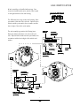
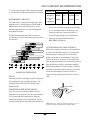
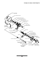
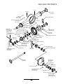
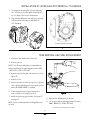
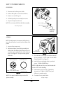
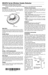
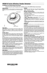
Spicer Tandem Drive Axles ® Service Manual Spicer® Tandem Drive Axles AXSM-1951 September 1997 S400-S TABLE OF CONTENTS Axle Identification .................................................................. 1 Model Identification Numbering System ......................... 2 Gear Set Identification ......................................................... 2 Axle Lubricant Recommendations ...................................... 3 General Precautions .............................................................. 4 Components Power Divider ............................................................... 5 Forward Rear ................................................................ 6 Rear Rear ....................................................................... 7 Removal of Differential Carrier from Axle Housing ........ 8 Removal of Differential from Carrier ................................. 9 Disassembly Inter-axle Differential .................................................. 10 Output Shaft ................................................................ 12 Differential .................................................................... 13 Pinion ............................................................................. 14 Cleaning and Inspection ...................................................... 15 Assembly Pinion ............................................................................. 16 Differential .................................................................... 19 Assembly (Continued) Output Shaft ................................................................ 20 Inter-axle Differential .................................................. 21 Differential Installation ......................................................... 23 Ring Gear and Tooth Contact Pattern .............................. 24 Installation of Inter-axle Differential Into Carrier ........... 25 Yoke Removal and Seal Replacement ................................ 25 Shift Cylinder Service ........................................................... 26 Installation of Differential Carrier Into Axle Housing .... 27 Axle/Torque Specifications.................................................. 28 Recommended Service Tools .............................................. 29 GENUINE SPICER SERVICE PARTS Should an axle assembly require replacement component parts, it is recommended that Spicer Heavy Axle Service Parts be used. Spicer Heavy Axle Service Parts are manufactured under the same rigid specification as are original equipment axle components. This assures the customer who uses genuine Spicer service parts, maximum reliability for a Spicer Heavy Axle assembly. They may be obtained through your vehicle manufacturer. The use of non-original Spicer service parts may cause premature component failure and may void the warranty. The items included in this book are currently being offered as service parts at the time of printing. The part numbers and illustrations are provided specifically for reference purposes only. Therefore, Spicer reserves the right to update this manual without notice or liability. i AXLE IDENTIFICATION All axle assemblies are identified with two tags. One located on the differential carrier, and the other located on the right hand side of the axle housing. JULIAN D ATE CODE DA 97 1 70 17 The differential carrier tag contains the following: Dana part number, julian date code, and ratio. Optional items include customer part number, line set number, and the last six digits of the vehicle serial number. MODEL YEAR DANA P AR T PAR ART NUMBER The axle assembly tag contains the following items: Dana part number, julian date code, axle model, and ratio. Optional items include customer part number, line set number, and the last six digits of the vehicle serial number. DAY OF YEAR CUS TOMER CUST T NUMBER ART PAR (OPTIONAL) Carrier T ag Tag LAS T SIX DIGITS OF LAST VEHICLE SERIAL NUMBER (OPTIONAL) DANA P AR T PAR ART NUMBER CUS TOMER CUST PAR T NUMBER ART (OPTIONAL) MODEL JULIAN D ATE DA CODE Axle A ssembl ag Assembl ssemblyy T Tag LAS T SIX DIGITS OF LAST VEHICLE SERIAL NUMBER (OPTIONAL) LINE SET NUMBER (OPTIONAL) 1 LINE SET NUMBER (OPTIONAL) JULIAN D ATE DA CODE MODEL IDENTIFICATION NUMBERING SYSTEM S 400 S N Famil amilyy (S = Spicer) Nominal Load Carr ying Capacit Carrying Capacityy (400 = 40,000 Lbs.) Gearing T ype Type (S = Single R educ tion) Reduc eduction) Op tions Options (N = *No-SPIN® Differ ential) Differential) * No-SPIN® is a registered trademark of Tractech GEAR SET IDENTIFICATION Manufacturer's Date- Date gear set was made. PINION ETCH SPICER TRADEMARK Spicer Trademark- Company logo and location of manufacturing facility. +15 Part number of pinion- 390GP100 (TYPICAL) Tooth Combination(i.e. 41-11)- Indicates the pinion has 11 teeth and the ring gear has 41 teeth which results in a 3:73:1 ratio. 260 41-11 TOOTH COMBINATION Matched Set Number- Spicer ring gears and pinions are manufactured as matched sets. Both ring gear and pinion are marked with a corresponding number (i.e. 260), which identifies them as a matched set. PART NUMBER HEAT CODE SPICER TRADEMARK MFG. DATE MATCHED SET NUMBER 260 L10 A gear set that does not have the same match set numbers should not be run together. If either ring gear or pinion require replacement, a new matched set must be used. BACKLASH ETCH Backlash etch- Indicates backlash setting for assembly. 2 AXLE LUBRICANT RECOMMENDATIONS To ensure proper lubrication and operating temperature, correct lubricants and lubricant levels must be obtained. APPLICATION On Highway PETROLEUM BASED MILES INTERVAL SYNTHETIC BASED** MILES INTERVAL 100,000 1 Year 250,000 3 Year and 50,000 On-Off Highway 1 Year 100,000 1 Year * Severe Service RECOMMENDED LUBRICANTS Petroleum based or synthetic based hypoid gear lubricants that meet or exceed military specification MIL-L2105D, and API service classification GL-5, are the minimum requirements for use in Spicer Medium and Heavy Duty Drive Axles. * The table below indicates which SAE viscosities are recommended for various temperature ranges the vehicle will encounter. Severe service includes any applications operating at or near maximum GVW or GCW ratings. This includes normally wet or dusty environment, or consistent high load and low speed applications. ** Includes Semi-Synthetic blends that meet MIL-L-2105D specifications. AFTER OVERHAUL OR CHANGE INTERVALS Fill the axle assembly to the bottom of housing fill hole as shown in the illustration below. It is recommended that following an overhaul, each side of the axle be jacked up separately to approximately six inches and held into position for one minute. This procedure will allow adequate lubricant to flow into the wheel ends and help eliminate the possibility of premature damage to wheel bearings and seals. Lower the vehicle to the floor and allow ten minutes for lube to return to normal level. Check and refill assembly to bottom of fill hole to replace the lubricant that was directed into the wheel ends. AMBIENT AIR TEMPERATURE SERVICE Recommended lubricant change intervals are dependent on the application and operating environment. The following chart should be used to establish proper change intervals. SUBMERSION OR DEEP WATER FORDING In the event the axle assembly should become submerged in water, particularly if over the vent or breather, it is recommended that the lubricant be drained to prevent water damage and/or contamination. The axle assembly should then be refilled with specified lubricant. NOTE: Lubricant close enough to the bottom of the fill hole to be seen or touched is not sufficient. Lubricant must be level with the fill hole. 3 GENERAL PRECAUTIONS IMPORTANT READ THIS SECTION BEFORE STARTING ANY SERVICE PROCEDURES GENERAL AXLE DESCRIPTION The Spicer tandem rear axle assemblies consist of two heavy duty, hypoid, single reduction differential carrier assemblies. The forward axle contains a power divider, which does exactly what its name implies. It divides power between the forward rear and rear rear axle assemblies. Accordingly, anyone who uses a service procedure or tool different than shown must first thoroughly satisfy themselves that their safety, nor the vehicle safety, will be jeopardized by the service method selected. END YOKES AND FLANGES CAUTION: Hammering on end yokes could damage the bearing bores or misalign yoke lugs and result in early failures of journal needle bearings or other driveline components. Serious damage can also be done internally to the ring and pinion set or pinion bearings by hammering on external parts. End yokes or companion flanges should be removed or installed using the recommended method such as that described herein. The forward axle receives power through a set of helical gears within the power divider. The rear rear axle receives power from the power divider output shaft that extends through the forward axle housing. The complete forward axle differential carrier assembly and power divider can be removed from the axle housing as a unit. Follow the sections of this manual that cover individual service needs. Safety glasses should be worn at all times when assembling or disassembling axles. SAFTEY PRECAUTIONS Proper service and repair of vehicle components is important to the safe and reliable operation of all motor vehicles. This applies particularly to driving axles such as the ones described in this manual. The procedures recommended and described in this manual are tested, and effective methods for performing service operations. Follow each procedure closely, making use of both the text and illustrations. Some of these service procedures show the use of certain tools designed specifically for the operation being performed. They are shown as a preferred means of performing the operation. It is not practical to anticipate and advise the service trade of all possible alternative methods, and of all possible hazardous consequences that could result from any particular method. CLEANLINESS Axle components should be steam cleaned prior to removal from the vehicle. Dirt is abrasive and can cause premature wear of otherwise serviceable parts. Service personnel should use a wash tank for thorough cleaning of parts just prior to reassembly. CAUTION BRAKE LININGS CONTAIN NON-ASBESTOS FIBERS BREATHING BRAKE DUST MAY BE HAZARDOUS TO YOUR HEALTH AND MAY CAUSE SERIOUS RESPITORY OR OTHER BODILY HARM. AVOID CREATING DUST DO NOT REMOVE BRAKE DRUM WITHOUT PROPER PROTECTIVE EQUIPMENT. DO NOT WORK ON LININGS WITHOUT PROPER PROTECTIVE EQUIPMENT. DO NOT REPLACE LININGS WITHOUT PROPER PROTECTIVE EQUIPMENT. DO NOT ATTEMPT TO SAND, GRIND, CHISEL, FILE, HAMMER OR ALTER BRAKE LININGS IN ANY MANNER WITHOUT PROPER PROTECTIVE EQUIPMENT. FOLLOW 0.S.H.A. STANDARDS FOR PROPER PROTECTIVE DEVICES TO BE USED WHEN WORKING WITH BRAKE MATERIALS. 4 POWER DIVIDER COMPONENTS Fill Plug (35- 45 Lb-Ft) (47-61 N-m) Inter-axle Differential Case Inter-axle Differential Bearing Cup Inter-axle Differential Bearing Cone Inter-axle Differential Side Gear Inter-axle Differential Assembly Helical Drive Gear Needle Bearing Flange Hex Bolt (160-180 Lb-Ft) (217-244 N-m) Needle Thrust Bearing Assembly Magnetic Drain Plug (35- 45 Lb-Ft) (47-61 N-m) Input Shaft Lube Retainer Washer Clutch Collar Hex Bolt (20-25 Lb-Ft) (27-34 N-m) Input Bearing Cone Input Bearing Cup Input Shaft Bearing Shim (Selective) Input Shaft Bearing Retainer Shift Fork Input Oil Seal Compression Spring Yoke Spacer Shift Shaft Piston Assembly Shift Cover O-ring Shift Cover Washer Shift Cover Bolt (15 - 20 Lb-Ft) (20-27 N-m) 5 Input Shaft Bearing Retainer Bolt (100-120 Lb-Ft) (136-163 N-m) Input Yoke Assembly Flanged Hex Nut (900-1,200 Lb-Ft) (1,220-1,627 N-m) FORWARD REAR COMPONENTS Flanged Hex Nut (900-1,200 Lb-Ft) (1,220-1,627 N-m) Output Yoke Assembly Output Oil Seal Axle Shaft ( Roadside ) Beveled Retaining Ring Output Shaft Bearing Output Shaft Fill Plug (35-45 Lb-Ft) (47-61 N-m) Temperature Sensor Plug (35-45 Lb-Ft) (47-61 N-m) Vent Plug Differential Bearing Cap Bolt (295-340 Lb-Ft) (400-461 N-m) Differential Side Bearing Cap Axle Housing Dowel Pin Differential Gear Thrust Washer Differential Case Bolt (180-200 Lb-Ft) (244-271 N-m) Differential Case Cap Half Magnetic Drain Plug (35-45 Lb-Ft) Ring Gear Bolt (47-61 N-m) Differential Case Flange Half Flat Washer Nut (300-320 Lb-Ft) (407-434 N-m) Differential Side Gear Differential Cross Shaft Differential Pinion Mate Differential Pinion Mate Thrust Washer Flat Washer Adjusting RingLock Ring Gear Adjusting Ring Lock Bolt (30-40 Lb-Ft) (41-54 N-m) Hex Bolt (150 Max. Lb-Ft) (203 Max. N-m) Differential Bearing Cone Pinion Pilot Bearing Cap Pinion Pilot Bearing Differential Bearing Cup Adjusting Ring Pinion Dowel Pin Inner Pinion Bearing Cone Inner PinionBearing Cup Pinion Bearing Spacer (selective) Axle Shaft ( Curbside ) Outer Pinion Bearing Cup Carrier Housing Carrier Mounting Bolt (240-260 Lb-Ft) (325-353 N-m) Outer Pinion Bearing Cone Helical Driven Gear 6 Flanged Hex Nut (900- 1200 Lb-Ft) (1,220-1,627 N-m) REAR REAR COMPONENTS Housing Vent Plug Axle Shaft ( Roadside ) Fill Plug (35-45 Lb-Ft) (47-61 N-m) Differential Bearing Cap Temperature Sensor Plug (35-45 Lb-Ft) (47-61 N-m) Dowel Pin Magnetic Drain Plug (35-45 Lb-Ft) (47-61 N-m) Differential Bearing Cap Bolt (295-340 Lb-Ft) (400-461 N-m) Nut (300-320 Lb-Ft) (407-434 N-m) Differntial Pinion Mate Thrust Washer Differential Bearing Cap Washer Differential Pinion Mate Differential Cross Shaft Differential Side Gear Ring Gear Flat Washer Differential Case Cap Half Ring Gear Ring Gear Bolt Hex Bolt (150 Max. Lb-Ft) (203 Max. N-m) Pinion Pilot Bearing Differential Bearing Cone Adjusting Ring Lock Adjusting Ring Lock Bolt (30-40 Lb-Ft) (41-54 N-m) Differential Gear Thrust Washer Differential Case Bolt (180-200 Lb-Ft) (244-271 N-m) Differential Bearing Cup Adjusting Ring Differential Case Flange Half Pinion Pinion Pilot Bearing Cap Inner PinionBearing Cone Inner Pinion Bearing Cup Pinion Bearing Preload Spacer (Selective) Outer Pinion Bearing Cup Outer Pinion Bearing Cone Axle Shaft ( Curbside ) Carrier Housing Carrier Mounting Bolt (240-260 Lb-Ft) (325-353 N-m) Pinion Oil Seal End Yoke Assembly Flanged Hex Nut (900-1,200 Lb-Ft) (1,220-1,627 N-m) 7 REMOVAL OF DIFFERENTIAL CARRIERS FROM AXLE HOUSINGS NOTE: Steam clean axle assembly. 10. Separate differential carrier from the housing using removal slots. See Figures 1 and 2. Be certain differential carrier clears dowel pins and is balanced properly on jack. Remove top two carrier mounting bolts, and remove differential carrier assembly from the axle housing. 1. Block wheels. 2. Remove axle housing and power divider drain plugs and drain lubricant. 3. Disconnect drive shaft at the rear U-joint. NOTE: If end yoke and/or seal is to be replaced, loosen yoke nut at this time. 4. Match mark each axle shaft flange to its mating wheel end and remove axle shaft flange nuts. Removal slot Dowel Pin IMPORTANT: Axle shafts are of different lengths and should be marked accordingly for proper reassembly. 5. Hold a large brass drift or a brass hammer against the center of the axle shaft flange. Strike the drift with sharp blows from a large hammer or sledge until the axle shaft separates from the hub. Dowel Pin Removal slot Power Divider Drain Plug CAUTION: Do not strike the flange directly with a steel hammer or sledge. This may crack and splinter material, possibly causing serious or fatal injury. Do not pry or chisel axle flange away from hub or damage to sealing surfaces could occur. Figur iguree 1 6. Remove axle shafts. Remember due to different length axle shafts, each shaft should be marked to mating wheel end for proper reassembly. Removal slot 7. Disconnect air line from power divider shift cover on forward rear assembly. 8. Support the differential carrier assembly on a roller jack. Secure as necessary to prevent it from falling off the jack when removed from the housing. Removal slot 9. Loosen the differential carrier-to-housing mounting bolts. Remove all bolts except top two. These two bolts will prevent the carrier assembly from falling. Figur iguree 2 11. Mount carrier assembly in a suitable rebuild stand. (Refer to RECOMMENDED SERVICE TOOLS, pgs. 29-30) IMPORTANT: Thread two guide pins into axle housing to relieve weight from output shaft bearing assembly of forward rear during differential carrier removal. Differential Carrier Removal Complete 8 REMOVAL OF DIFFERENTIAL FROM CARRIER The following service procedures apply for both forward rear and rear rear axles, unless otherwise noted. IMPORTANT: If the ring and pinion is to be reused, ring gear backlash should be checked and recorded before disassembly. Backlash should be reset to this specification after completion of repairs. For backlash specifications refer to DIFFERENTIAL INSTALLATION. 1. Remove adjusting ring bolts and locks from bearing caps. 2. One differential bearing cap and leg of the carrier is match marked to aid during reassembly. See Figure 3. 3. Loosen four bearing cap retaining bolts. 4. Loosen adjusting rings, to relieve bearing preload. Figur iguree 3 5. Remove four bearing cap retaining bolts and washers. 6. Remove bearing caps. 7. Remove adjusting rings and bearing cups. NOTE: If bearings are to be reused, cups must stay with mated cones. They can not be interchanged. 8. Carefully lift the ring gear and differential subassembly out of carrier. NOTE: The ring gear side of subassembly must be tipped up for the ring gear to clear the pinion pilot bearing cap. Removal of Differential Complete 9 INTER-AXLE DIFFERENTIAL DISASSEMBLY Fill Plug (35-45 Lb-Ft) (47-61 N-m) Inter-axle Differential Case Bearing Cup Bearing Cone Inter-axle Differential Side Gear Inter-axle Differential Assembly Helical Drive Gear Needle Bearing Needle Bearing Thrust Washer Assembly Bolt (160-180 Lb-Ft) (217-244 N-m) Drain Plug (35-45 Lb-Ft) (47-61 N-m) Lube Retainer Input Shaft Washer Clutch Collar Bolt (20-25 Lb-Ft) (27-34 N-m) Bearing Cone Bearing Cup Shift Fork Shim (Selective) Input Shaft Bearing Retainer Spring Seal Spacer Shift Shaft Piston Assembly Shift Cover O-ring Shift Cover Washer Shift Cover Bolt (15 - 20 Lb-Ft) (20-27 N-m) Bolt (100-120 Lb-Ft) (136-163 N-m) Input Yoke Assembly Flanged Hex Nut (900-1,200 Lb-Ft) (1,220-1,627 N-m) 1. Remove intermediate case to carrier bolts. Use removal slots to seperate inter-axle differential case from carrier. See Figure 4. 2. With inter-axle differential assembly removed, remove four bolts and washers of shift cylinder. 3. Remove shift cylinder cap and piston. NOTE: It may be necessary to tap piston lightly with soft mallet to remove. Removal slot 4. Remove shift cylinder shaft. Removal slot 5. Remove flanged hex nut. Figur iguree 4 10 INTER-AXLE DIFFERENTIAL DISASSEMBLY NOTE: Use of a torque multiplier is recommended as torque specification on input flanged hex nut is 9001,200 Lb-Ft (1,220-1,627 N-m). (Refer to RECOMMENDED SERVICE TOOLS, pgs. 29-30) 8. Remove input oil seal 6. Remove input yoke using a suitable puller. See Figure 5. 10. Remove input shaft assembly. Remove input yoke spacer from input shaft. 9. Press out input shaft bearing cup from bearing retainer. Retain shims for possible use during reassembly. Early models were not a press fit. 11. Remove front bearing cone from input shaft using suitable puller. 12. Remove clutch collar, shift fork, and spring from assembly. Yoke Remover 13. Remove needle thrust bearing assembly from top of drive gear. 14. Remove drive gear from inter-axle differential case. 15. Remove two lube retainer bolts. 16. Remove lube retainer. 17. Remove inter-axle differential assembly from case. Figur iguree 5 18. Remove rear Diff-gear from inter-axle differential case. 7. Remove bolts from input shaft bearing retainer. Use removal slots (See Figure 6) to seperate bearing retainer from inter-axle differential case, and remove retainer. 19. Remove rear bearing cup from intermediate case. 20. Remove bearing cone from rear differential gearusing a suitable puller. 21. Clean and inspect all components for excessive wear, scoring, or cracks. Replace damaged components with original equipment replacement parts and prepare for reassembly. Inter-Axle Differential Disassembly Complete Removal slot Removal slot Figur iguree 6 11 OUTPUT SHAFT DISASSEMBLY Flanged Hex Nut (900-1,200 Lb-Ft) (1,220-1,627 N-m) End Yoke Beveled Retaining Ring Output Shaft Housing Output Shaft Bearing Output Oil Seal 1. Remove the inter-axle drive shaft. 6. Place output shaft remover adapter into housing bore. NOTE: Power divider must be engaged so shaft will not rotate. 7. Thread yoke installer service tool onto output shaft. See Figure 7. 2. Remove output flanged hex nut. 8. Tighten nut on yoke installer to pull output shaft bearing assembly out of housing. NOTE: Use of torque multiplier is recommended as torque specification on output nut is 900-1,200 LbFt (1,220-1,627 N-m). 9. If output shaft bearing is to be replaced, remove old bearing using a suitable puller or press. 3. Remove output yoke using a suitable puller. NOTE: It is important to place the Output Shaft Remover Adapter on with the shoulder to the outside. See Figure 7. 4. Remove oil seal. 5. Remove beveled retaining ring. Output Shaft Removal Complete Yoke Installer Service Tool # DST1007 Output Shaft Remover Adapter w/Shoulder Facing Out Figur iguree 7 12 Housing Output Shaft Bearing Assembly DIFFERENTIAL DISASSEMBLY Bearing Cup Bearing Cone Pinion Mate Thrust Washer Differential Cross Shaft Differential Case Bolt (180-200 Lb-Ft) (244-271 N-m) Plain Half Differential Case Differential Gear Bolt Ring Gear Flange Half Differential Case Flat Washer Nut (300-320 Lb-Ft) (407-434 N-m) Bearing Cup Differential Pinion Mate Gear Thrust Washer Bearing Cone 1. Match mark differential case halves with a punch or chisel for correct alignment in reassembly. See Figure 8. Figur iguree 9 NOTE: Inspect all parts including the machined surfaces of the case itself. IMPORTANT: If any gears are to be replaced, they must be replaced in sets. Inspect thrust washers for scoring and excessive wear. Replace all worn or damaged parts. Figur iguree 8 2. Remove differential case bolts and lift off the differential case half. 7. When it is necessary to remove ring gear from differential case, carefully loosen ring gear nuts with breaker bar in an alternating pattern and remove. 3. Remove thrust washer and differential gear. 4. Lift out cross shaft, pinion mates and pinion mate thrust washers. IMPORTANT: Do not damage ring gear when loosening ring gear nuts. 5. Remove second differential gear and thrust washer. 6. If differential bearings are to be replaced, remove old bearings using a suitable puller. See Figure 9. 8. Inspect ring gear, ring gear bolts, and ring gear bolt holes for nicks, excessive wear, and irregularities. 13 Differential Disassembly Complete PINION DISASSEMBLY 1. Remove flanged hex nut. face up. See Figure 10 and 10A. NOTE: Use of a torque multiplier is recommended. Torque flanged hex nut to 900-1,200 Lb-Ft (1,2201,627 N-m). 7. Place a wooden block under pinion to avoid damage of gear teeth during removal. 8. Pinion removal - 2. Remove end yoke on the rear rear axle using a suitable puller. Refer to RECOMMENDED SERVICE TOOLS, pgs. 29-30). 3. Remove the oil seal on the rear rear axle and discard. 4. Remove the four pinion pilot bearing support bolts. • On the Forward Rear, press the pinion through the helical driven gear and inner and outer bearing cones. See Figure 10. • On the Rear Rear, press the pinion through the inner and outer bearing cones. See Figure 10A. 9. Remove the pinion from the bottom of the carrier. 5. Remove the pinion pilot bearing support. 10. Remove bearing preload spacer and save for use in reassembly. 6. Place carrier in press with threaded end of pinion 11. If the gearset is to be reused, remove inner pinion bearing with a suitable puller at this time. If the gear set is to be replaced new bearings must be installed. Press Pinion 12. If bearings are to be replaced, press bearing cups out of carrier casting at this time. Driven Gear 13. Remove pinion pilot bearing with a suitable puller. Pinion Disassembly Complete Press Wood Block Pinion Figur 0 iguree 1 10 Wood Block Figur 0A iguree 1 10A 14 CLEANING AND INSPECTION CLEANING GEARS 1. Parts should be cleaned with emulsion cleaners or petroleum base cleaning solvent. NOTE: Alkaline type solutions may cause damage to machined surfaces and should be avoided. 2. Make sure interior of axle housing is clean prior to reassembly. 3. Clean all gasket surfaces of old material. DRYING Use soft, clean, lintless towels or rags to dry components after cleaning. Bearings should not be dried by spinning with compressed air. This can damage mating surfaces due to the lack of lubrication. Inspect gears for excessive wear or damage. Replace gears that are pitted, scored, broken, or worn. SHAFTS After drying, parts should be coated with a light coat of lubricant or rust inhibitor to prevent damage from corrosion. If parts are to be stored for a prolonged period, they should be wrapped in wax paper. Inspect shafts for nicks or scoring. INSPECTION Prior to reassembly, inspect parts for signs of excessive wear or damage. Replacement of these parts can prevent premature failure and costly downtime. SPLINES Inspect all splines for excessive wear, distortion from twisting, and cracking. BEARINGS Bearing surfaces should be inspected for pitting, excessive wear, or overheating. HOUSINGS THRUST WASHERS Inspect thrust washers for scoring and cracking. Inspect housing for stripped threads and bending fatigue. 15 PINION ASSEMBLY NOTE: Alkaline type solutions may cause damage to machined surfaces and should be avoided. 3. Stake pilot bearing in nine places using a center punch or equivalent tool. See Figure 13. 4. Press inner and outer bearing cups into the carrier Feeler Gauge Figur 1 iguree 1 11 1. Press inner bearing cone onto pinion. See Figure 11. 2. Press pinion pilot bearing onto the pinion. See Figure 12. Figur 4 iguree 1 14 until seated. Use a feeler gauge (.0015 inch) to make sure that bearing cups are fully seated in bearing bores. Apply hypoid gear lubricant to both cup and cone. See Figure 14. Press Pinion Pilot Bearing Press Outer Pinion Bearing Bearing Preload Spacer Pinion Pinion Figur 2 iguree 1 12 NOTE: Chamfer side of bearing faces the pinion head. Wood Block Figur 5 iguree 1 15 NOTE: After installing pinion bearing and or helical gear, pinion shaft should be turned at least 8 rotations to assure proper alignment of bearing rollers. Figur 3 iguree 1 13 16 PINION ASSEMBLY 5. Place carrier housing in press with the pinion supported by wood block (6"X6"X6"), so the inner pinion bearing is mated to the cup. See Figure 15. 6. Insert original preload spacer and outer pinion bearing onto pinion. Yoke Installer Service Tool 7. Press outer pinion bearing onto pinion until completely seated. 8. On forward rear, press driven gear onto pinion. See Figure 16. IMPORTANT: The old style driven gear on the 3.21 and 3.42 ratios will have FRONT stamped on the face of the gear. This gear must be installed with the word FRONT facing away from the carrier assembly. If you do not have this driven gear no special instructions apply to the installation of the gear. Figur 7 iguree 1 17 900-1,200 Lb-Ft (1,220-1,627 N-m). 12. Install pinion pilot bearing cap. Tighten and torque four bolts to 150 Lb-Ft (203 N-m). 9. On rear rear carrier, inspect end yoke or companion flange, for grooves in seal surface. If grooves can be 13. Measure torque to rotate with an inch-pound torque wrench. Make eight revolutions, taking a torque measurement every fourth revolution. It should read between 10-40 lb-in of bearing preload. See Figure 18. Press Driven Gear NOTE: If bearing preload does not fall within allowed limits, preload can be increased by using a thinner spacer and decreased by using a thicker spacer. .001 inch change in preload spacer will change torque to rotate approximately 30 lb-in. Figur 6 iguree 1 16 detected with finger-nail, then end yoke must be repaired with a C/R approved repair sleeve or replaced. 10. Use yoke installer service tool and install yoke without seal. See Figure 17. 11. Use torque multiplier and torque flanged hex nut to 17 Figur 8 iguree 1 18 PINION ASSEMBLY NOTE: Individual carriers may vary slighty. NOTE: Closer adjustment can be made by sanding the next thicker spacer to desired thickness using emery cloth on a flat surface. Pinion bearing preload spacers are available in the following thicknesses: inch mm inch mm .718 .719 .720 .721 .722 .723 .724 .725 .726 .727 .728 .729 .730 18.24 18.26 18.29 18.31 18.34 18.36 18.39 18.41 18.44 18.47 18.49 18.52 18.54 .731 .732 .733 .734 .735 .736 .737 .738 .739 .740 .741 .742 18.57 18.60 18.62 18.64 18.67 18.69 18.72 18.75 18.77 18.80 18.82 18.85 CAUTION: Wash spacer thoroughly of emery cuttings before installing on pinion. 14. Repeat process until torque to rotate is between 10-40 lb-in after preload is achieved, remove yoke and install new seal with proper service tool. NOTE: Acceptable torque to rotate with seal installed is 15-45 lb-in. 15. Install yoke using yoke installer (See RECOMMENDED SERVICE TOOLS, pgs. 29-30) NOTE: Spicer recommends that new flanged hex nuts be used. 16. Apply Loctite #680 (green) to threads. 17. Use torque multiplier and torque flanged hex nut to 900-1,200 Lb-ft (1,220-1,627 N-m). Always measure each spacer before assembly to ensure correct thickness. Pinion Assembly Complete 18 DIFFERENTIAL ASSEMBLY Bearing Cup Bearing Cone Pinion Mate Thrust Washer Differential Cross Shaft Differential Case Bolt (180-200 Lb-Ft) (244-271 N-m) Bolt Ring Gear Plain Half Differential Case Differential Side Gear Flange Half Differential Case Flat Washer Nut (300-320 Lb-Ft) (407-434 N-m) Bearing Cup Differential Pinion Mate Gear Thrust Washer Bearing Cone 1. If ring gear was removed from the differential case, reinstall it at this time. • Clean the differential case and ring gear mounting surface. • Position the differential case on a work bench with the machine surface down. • Place the ring gear on the case with the teeth facing up. • Install bolts into the tooth side of the ring gear and install the flat washer and nut onto the differential case side. 2. Press bearing cones onto differential case halves. Place bearing cups on cones during remainder of assembly to prevent damage of bearings. 3. Apply a small amount of hypoid axle lubricant to all mating surfaces. This will aid in assembly by keeping parts together and providing initial lubrication. 4. Place gear thrust washer and differential side gear in differential case flange half. 5. Assemble pinion mates and pinion mate thrust washers onto differential cross shaft. Place assembly into flange half differential case. NOTE: Bolts have a clearance fit in the differential case and the ring gear mounting holes. Bolts require correct torque to ensure proper clamp. • 6. Place remaining differential side gear and thrust washer in position on differential pinion mates. When all bolts have been installed, tighten opposite one another until one half the prescribed torque is obtained. 150-160 Lb-Ft (204-217N-m) 7. Assemble case halves, making sure match marks are lined up. 8. Install differential case bolts. Tighten alternately and torque evenly to 180-200 Lb-Ft (244-27N-m). NOTE: Bolt heads must be held flat against ring gear while torque is being applied. • NOTE: If old bolts are used, coat threads with Loctite #277 before installing. Repeat the process to full torque specifications. 300-320 Lb-Ft (407-434 N-m) Differential Assembly Complete 19 OUTPUT SHAFT ASSEMBLY End Yoke Flanged Hex Nut (900-1,200 Lb-Ft) (1,220-1,627 N-m) Output Shaft Beveled Retaining Ring Output Oil Seal Housing Output Shaft Bearing 1. Press new bearing onto shaft using output shaft bearing installer service tool. See Figure 19. 3. Install output shaft and bearing assembly into housing using bearing installer service tool withadequate 2 jaw puller. See Figure 20. NOTE: Clean bore of housing to remove old Loctite and oil. 4. Seat bearing completely in housing and remove excess Loctite. Bearing Installer Service Tool 5. Install beveled retaining ring in housing with bevel facing to the rear of the axle. Be certain the retainer ring is fully seated. Clean and dry threads on output shaft. 6. Lubricate bearing with hypoid axle lube. 7. Install oil seal using proper service tools. 8. Install end yoke using yoke installer service tool. Figur 9 iguree 1 19 2. Apply a thin layer of Loctite #620 to the outside diameter of the bearing before assembly into housing. 9. Apply Loctite #680 to threads before installing new flanged hex nut. 10. Use torque multiplier and torque flanged hex nut to 900-1,200 Lb-Ft (1,220-1,627 N-m). NOTE: Care must be taken to keep Loctite out of bearing. Output Shaft Installation Complete Bearing Installer Service Tool 2-Jaw Puller FFigur igur 0 iguree 2 20 20 Housing INTER-AXLE DIFFERENTIAL ASSEMBLY 1. Position inter-axle differential case on two 4" x 4" blocks for reassembly Tap nut lightly with soft hammer. 15. Position dial indicator onto end of input shaft. See Figure 21. 2. Install new rear differential bearing cup into case. 3. Press new bearing cone onto rear differential gear. NOTE: Be certain that both cup and cone are seated properly or false reading on end play of inter-axle may occur. 4. Apply a light coating of gear lube to rear diff-gear bearing, hub surface, and interior bore, then install.. 5. Lubricate and place inter-axle differential assembly inside of plastic lube retainer and install into case. 6. Align the bolt holes of the plastic lube retainer with the case and install the two bolts and washers. Tighten and torque lube retainer bolts to 20-25 Lb-Ft (27-34 N-m). Figur 1 iguree 2 21 Using suitable pry bar and spacer, pry input shaft out and record end play. 8. Lubricate needle bearing and carefully lower drive gear into intermediate case until differential gear is seated in inter-axle differential. 16. Proper end play for inter-axle is .001 to .003 inch (.025 to .076 mm). Subtract .003 inch (.076 mm) from recorded end play and assemble combination of shims that total proper thickness to establish correct end play. 9. Press input shaft front bearing cone onto shaft until seated completely against shoulder. EXAMPLE: Measurement with dial indicator. .080in. (2.032 mm) 10. Lube the needle thrust bearing lightly and place on front drive gear. Ensure that thin bearing race is seated against drive gear and the thrust bearing is seated between the two spacers. Preferred end play. .003in. (0.076 mm) Required shims. .077in. (1.956 mm) 7. Press new needle bearing into I.D. of drive gear. 17. Remove input shaft bearing retainer and install shim pack between bearing retainer and input shaft bearing cup. Remove input shaft. NOTE: To establish proper end play, input shaft will be installed into inter-axle differential prior to installing shift collar, fork , and shift shaft. 18. Install shift spring into the bottom of the shift well. 11. Lube and install input shaft, turning slightly to engage splines. 19. Check shift fork for excessive wear. Replace if necessary. 12. Install new input shaft front bearing cup into input shaft bearing retainer without shims. 20. Check clutch collar for wear or damage in groove, on drive lugs, and splines. Replace if necessary. 13. Install bearing retainer onto intermediate housing and bolt into place. 21. Apply a thin coat of grease on the clutch collar riding surface area of shift fork. 14. Thread input flanged hex nut onto input shaft until resistance is felt from locking compound. 21 INTER-AXLE DIFFERENTIAL ASSEMBLY 22. Assemble the shift collar onto the shift fork with flat side of collar up. The fork bushing must also face up. Install the fork and collar into the case and align the hole of the shift fork over the opening of the spring. 32. Install new oil seal into input shaft bearing retainer. 23. Apply a thin coat of grease to the small diameter of the shift shaft. of case and around each bolt hole. See Figure 22. 33. Clean the mating surfaces of the bearing retainer and the case. Apply a 1/16 in. bead of Loctite #518 Gasket Eliminator to cover mounting surface 34. Install bearing retainer and tighten bolts alternately. Torque bolts 100-120 Lb-Ft (135-163 N-m). 24. Insert shift shaft into cylinder and install through the shift fork hole and the spring. Make sure shaft is seated into the bottom of the shift cylinder. 35. Inspect input yoke seal surface for grooves. If grooves can be detected with fingernail, it must be repaired with a CR SPEEDI-SLEEVE® or replaced. 25. Apply a thin coat of grease to the O-ring of the shift piston. 36. Clean and dry threads on input shaft. NOTE: Visually inspect the composite shift piston to insure the steel spacer is present on the bottom of the piston. See page 26 for more piston information. 37. Install end yoke using installer service tool. NOTE: Spicer recommends that new flanged hex nuts be used. 26. Lubricate and place piston/O-ring assembly into shift cylinder with detailed side facing front for the composite piston and the flat face on the aluminum piston. See Figure 27 on page 26. Seat piston firmly against shift shaft. 38. Apply Loctite #680 (green) to threads. 39. Use torque multiplier and torque input flanged hex nut to 900-1,200 Lb-Ft (1,220-1,627 N-m). Inter-axle Assembly Complete 27. Install onto the shift cover. 28. Clean the shift cover sealing area and the intermediate case and apply a 1/16 in. bead of Loctite #518 Gasket Eliminator. See Figure 22. NOTE: Care must be taken to keep Loctite off of piston assembly. Loctite #518 Gasket Eliminator 29. Install shift cover. NOTE: If old bolts are used, coat threads with Loctite #277 before installing. 30. Install four washers and cover bolts. Tighten and torque bolts alternately to 15-20 Lb-Ft (20-27 Nm) until cover is seated properly. 31. Lube bearing and bearing journals then Install the input shaft into the shift collar and lube input shaft bearing. Figur 2 iguree 2 22 22 DIFFERENTIAL INSTALLATION 6. Loosen adjusting ring on tooth side of ring gear 1 notch and tighten adjusting ring on flange side of ring gear 1 notch. Repeat process until backlash is elminated. Tighten adjusting ring on tooth side of ring gear until the ring gear and pinion backlash matches the backlash etched on the ring gear. This adjustment sets both the backlash and the bearing preload. 1. Install ring gear and differential assembly into carrier housing. Tilt differential slightly so ring gear clears pinion pilot bearing support. NOTE: Care should be used when installing ring gear and differential into carrier housing so damage to ring gear, pinion, bearings, or bearing bores does not occur. 2. Differential bearings should be lubricated and bearing cups should be cleaned and #620 loctite applied to the O.D. of the bearings. 7. Check ring gear and pinion backlash in four equally spaced positions aound the ring gear with a dial indicator as shown. Acceptable backlash tolerance is +/- .002" from backlash etched on ring gear. (See Figure 24.) 3. Be sure side bearing cups are seated on bearing cones. Assemble differential bearing caps with match marks in proper location. Clean bearing cap bolts and washers and coat threads with Loctite #277(red). 4. Install bearing cap bolts and tighten enough to eliminate visible space between differential bearing cap and carrier. Do not torque bolts at this time. NOTE: Differential assembly must be aligned within bearing bores before preload is applied or damage to bearings can occur. 5. Install adjusting rings. Tighten both adjusting rings until end play is eliminated, and there is backlash between the ring gear and pinion. See Figure 23. Figur 4 iguree 2 24 NOTE: If the backlash tolerance varies more than .003" (.080mm) between the four positions, remove the differential and determine the cause. 8. Once the backlash is set, torque the differential bearing cap bolts to 295-340 Lb-Ft (400-461 Nm). Check backlash after torquing cap bolts. Differential Installation Complete Figur 3 iguree 2 23 23 RING GEAR AND PINION TOOTH CONTACT PATTERN STEP 1. Paint 1/4 ring gear with marking compound on both the drive and coast side. The procedures to the right are to be used to establish proper gear tooth pattern after assembly of the carrier is complete. STEP 2. Rotate ring gear at least one complete revolution in both directions while load is being applied. NOTE: If matched sets are being reused, measure and record backlash before disassembly, and reassemble to the same backlash. This will match ring and pinion gears to the established wear patterns. Hand rolled patterns will cover less area than the gear pattern established by previous service. TOE TOP LAND HEEL The GLEASON gear set is identified by a 390GA100 series part number. The ORLIKON is identified by a 390GA200 series part number. (See Gear Set Identification section.) PROFILE ROOT DRIVE SIDE (CONVEX) COAST SIDE (CONCAVE) CORRECT GEAR PATTERNS FOR GLEASON CUT GEARS LIGHTLY LOADED HEAVILY LOADED CORRECT GEAR PATTERNS FOR ORLIKON CUT GEARS LIGHTLY LOADED HEAVILY LOADED NOTE: Tooth contact pattern, on this axle model, can be moved only by adjusting backlash. The contact pattern can be moved in the direction of heel-to-toe, and toe-to-heel; Depth of the pattern cannot be adjusted. If an acceptable tooth contact pattern cannot be established within limits of backlash, contact Spicer Service at 1-800-666-8688. 24 INSTALLATION OF INTER-AXLE DIFFERNETIAL TO CARRIER 1. Thoroughly clean mating face of carrier and apply an 1/8 inch bead of Loctite #518 Gasket Eliminator. See Figure 19 for correct bead pattern. 2. Align inter-axle differential case with carrier housing and insert bolts and torque to 160-180 Lb-Ft (217-244 N-m). #518 Gasket Eliminator Bead Pattern Figur 9 iguree 1 19 YOKE REMOVAL AND SEAL REPLACEMENT 1. Disconnect drive shaft at the rear U-joint. 2. Remove yoke nut. NOTE: Use of torque multiplier is recommended as torque specification on input flanged hex nut is 9001,200 Lb-Ft (1,220-1,627 N-m). Yoke Remover 3. Remove end yoke using the yoke remover tool. See Figure 25. 4. Remove oil seal. 5. Inspect end yoke seal surface for grooves. If grooves can be detected with fingernail, it should be repaired with a CR SPEEDI-SLEEVE® or replaced. 6. Clean and dry threads on input/ouput shaft or pinion. Install oil seal using proper tools. Figur 5 iguree 2 25 7. Install end yoke using yoke installer. See Figure 17 on page 17. 8. Apply Loctite #680 (green) to threads. 9. Use torque multiplier and torque flanged hex nut to 900-1,200 Lb-Ft (1,220-1,627 N-m). NOTE: Spicer recommends that new flanged hex nuts be used. Yoke Removal and Seal Replacement Complete 25 SHIFT CYLINDER SERVICE DISASSEMBLY 1. Disconnect air line from power divider. 2. Remove shift cylinder cover bolts and washers. 3. Remove cover and O-ring seal. 4. Pull shift cylinder piston assembly from carrier. 5. Inspect all components for wear. NOTE: Do not remove shift fork shaft from assembly. Piston Assembly Seal, "O"-ring Disassembly Complete Shift Cover Washer Shift Cover Bolt (15-20 Lb-Ft) (20-27 N-m) ASSEMBLY NOTE: Visually inspect the composite shift piston to insure the steel spacer is present on the bottom of the piston. 1. Inspect all new components. 2. Lubricate and place piston/O-ring assembly into shift cylinder with detailed side facing front for the composite piston and the flat face on the aluminum piston. See Figure 27. Seat piston firmly against shift shaft. Composite Shift Piston Loctite 518 Gasket Eliminator Figur 8 iguree 2 28 3. Clean the shift cover sealing area and the intermediate case and apply a 1/16 in. bead of Loctite #518 Gasket Eliminator. See Figure 28. AluminumShift Piston 4. Install shift cover and tighten bolts to precribed torque. 15-20 Lb-Ft(20-27N-m) NOTE: If old bolts are to be used, coat threads with Loctite #277 before installing. Detail Faces Front (Found on early production models) (Found on later 5. Install washers and cover bolts. Tighten bolts alternately to 15-20 Lb-Ft (20-27 N-m) until shift cover is seated properly. production models) Figur 7 iguree 2 27 6. Connect air line to power divider. NOTE: Care must be taken to keep Loctite off of piston assembly. 26 Assembly Complete INSTALLATION OF DIFFERENTIAL CARRIER INTO AXLE HOUSING 7. Install the new axle flange gasket. 1. Thoroughly clean the inside of the carrier housing and inspect the housing mounting surface for nicks and general cleanliness. Stone the surface if necessary to remove burrs or nicks. 8. Install the axle shafts in proper location. Torque the axle flange nuts to vehicle manufacturers specifications. 9. Clean drain plug and fill unit to proper level with hypoid gear lubricant. 10. Apply Loctite #565, or its equivalent, to drain plug threads. Insert and torque to 35-45Lb-Ft (4761N-m). Differential Installation Complete Loctite #518 Gasket Eliminator Figur 9 iguree 2 29 2. Apply an 1/8 inch bead of Loctite #518 Gasket Eliminator onto the axle housing mounting flange and around each bolt hole. See Figure 29. 3. Thread 2 studs or guide pins into the axle housing 1800 apart. This will eliminate rotation of the carrier assembly after it makes contact with the gasket material. NOTE : Lubricant close enough to bottom of fill hole to be seen or touched is not sufficient. Lubricant must be level with the fill hole. CAPACITIES (Approximate): NOTE: Use guide pins to install forward carrier assembly with output shaft in housing. Align splines of output shaft and rear gear of inter-axle differential. This will help align carrier and output shaft during installation and prevent any unnecessary weight on output shaft bearing. Axle Forward Rear * Rear Rear ** 0 Pints 30 Liters 14 25 11.7 * Lube capacity is based on a 4 installation angle ** Lube capacity is based on a 110 installation angle 4. Install the carrier assembly into the axle housing. Clean the mounting bolts and coat with Loctite #277 (red), or its equivalent , and install Tighten bolts evenly in cross pattern. Torque bolts 240-260 Lb-Ft (330-338 N-m). 5. Allow one hour cure time for gasket material before adding hypoid gear lubricant. 6. Remove the old axle flange gasket and clean mating surfaces of the hub and axle flange. 27 AXLE / TORQUE SPECIFICATIONS S400-S Specifications Position U.S. Me tric Metric 10 - 40 Lb-in 1.1 - 4.5 N-m Pinion Torque Bearing Preload (Torque Wrench)* Differential .008 - .012 in. Ring Gear to Pinion Backlash .30 - .40 mm Lubrication (Approx.**) Forward Rear 30 Pts. 14 Liters Rear Rear 25 Pts. 11.7 Liters * Pinion bearing preload is established prior to installation of pinion seal. ** Capacity will vary depending on the housing angle in each vehicle. Fill to lower edge of fill hole in rear of axle housing as shown on Page 27. Forward Rear Fasteners Position Gr ade Grade Thr ead size Thread Lb-Ft N-m 1 3/4 12 900 - 1,200 5/8 11 8 240 - 260 330 - 358 3/4 14 3/4 14 35 - 45 47 - 61 Temperature Sensor Plug 1/2 14 35 - 45 47 - 61 Magnetic Drain Plug 3/4 14 35 - 45 47 - 61 Shift Cylinder Cap Bolts 5/16 18 8 15 - 20 20 - 27 Inter-Axle Differential Case Bolts 9/16 12 8 160 - 180 217 - 244 3/8 16 8 20 - 25 27 - 34 Thr ead size Thread Gr ade Grade Lb-Ft 1 3/4 12 900 - 1,200 Carrier Mounting Bolts 5/8 11 8 240 - 260 330 - 358 Fill Plug 3/4 14 35 - 45 47 - 61 Temperature Sensor Plug 1/2 14 35 - 45 47 - 61 Magnetic Drain Plug 3/4 14 35 - 45 47 - 61 Flanged Hex Nut Carrier Mounting Bolts Fill Plugs Lube RetainerBolts 1,220 - 1,627 Rear Rear Fasteners Position Flanged Hex Nut N-m 1,220 - 1,627 NOTE: Refer to vehicle manufactures specifications for Axle Flange - Wheel Nut fastener torque requirements. 28 RECOMMENDED SERVICE TOOLS ORDER NUMBER ILLUSTRATION DESCRIPTION DST1001 CARRIER STAND TORQUE MULTIPLIERS DST1002 DST1003 Maximum 1,000 Lb-Ft Maximum 2,000 Lb-Ft DST1004 DST1005 Maximum 4,000 Lb-Ft Maximum 12,000 Lb-Ft DST1006 YOKE REMOVER, BAR TYPE DST1007 YOKE INSTALLER (1-3/4"-12) DST1008 LONG, 2-JAW, PULLER 29 RECOMMENDED SERVICE TOOLS DS T1 000 DST1 T1000 S400 SER VICE KIT SERVICE ORDER NUMBER ILLUSTRATION DESCRIPTION DST1000-1 SEAL INSTALLATION HANDLE (To be used with seal installers listed below) DST1000-2 INPUT SHAFT SEAL INSTALLER OUTPUT SHAFT SEAL INSTALLER DST1000-3 PINION SEAL INSTALLER DST1000-4 OUTPUT SHAFT BEARING/ BEARING ASSEMBLY INSTALLER (To be used with 2-jaw puller) DST1000-5 OUTPUT SHAFT REMOVER ADAPTER (To be used with yoke installer DST 1007) ALL SERVICE TOOLS AVAILABLE FROM OTC DIVISION: Service Tools 655 Eisenhower Drive Owatonna, MN 55060 Telephone: 1-800-533-0492 Fax Number: 1-800-578-7375 30 Aftermarket Group ForDana spec‘ing or service assistance, call 1.800.621.8084 or visit our website at www.spicerparts.com PO Box 321 Toledo, Ohio 43697-0321 Warehouse Distributor: Dana Commercial Vehicle1.800.621.8084 Products Group OE Technology Dealers: 1.877.777.5360 3939 Drive Maumee, Ohio, USA 43537 www.spicerparts.com www.dana.com AXSM-1951 Printed in U.S.A. Copyright Dana Limited, 2012. All rights reserved. Dana Limited.