1
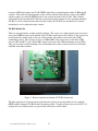
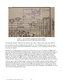
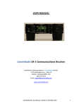
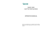
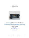
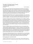
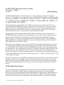
ICOM UX-R91 Broadcast Receive Mod
By Joseph Haas, KE0FF
2/19/2013
The ICOM UX-R91 module is a broad-band receive module designed specifically for the IC-901
Transceiver. The module covers six frequency bands: the AM broadcast band (0.5 to 1.6 MHz), the FM
broadcast band (WBFM, 76 – 108 MHz), the aircraft band (AM, 108 – 137 MHz), the 2M band (NBFM,
137 – 200 MHz), the 220 band (NBFM, 200 – 236 MHz), the 440 band (NBFM, 300 – 500 MHz), and
the 800 band (NBFM, 800 – 950 MHz).
This document details a modification to the UX-R91 to correct an issue with the broadcast receive
modes (both AM and FM broadcast bands are affected). The issue manifests as a low level, constant
amplitude white noise superimposed on the broadcast audio. It has been determined that this noise is
being coupled from the main band IC-901 receiver (including external modules) since it disappears
when the main-band receiver is quieted with a strong, no-modulation signal.
During the check-out of a recently acquired used IC-901, a white noise was noticed on one of the
UX-R91 FM broadcast stations that was being monitored as a test signal. This was attributed it to the
antenna, terrain, and distance to the transmitter since this station usually had difficulty in this area.
However, the noise was observed to disappear when the main band was quieted. After checking the
other UX-R91 bands, and other UX modules, the issue was determined to be limited to the broadcast
AM and FM bands of the UX-R91 module.
The easiest way to examine this issue is to tune the UX-R91 to a broadcast station, and insert a pair of
1/8” audio plugs (with nothing connected to the plugs) into the UX-R91 speaker jacks (located at the
rear of the module). Next, tune the main band (any FM frequency range) to an unused frequency with
the squelch closed. In this configuration, there will be a noticeable white-noise output from the IC-901
speaker. This noise is not affected by any of the volume controls (except if the sub-band volume is
turned all the way down). Turn the main band volume to zero and then quiet the main band by applying
an un-modulated RF signal strong enough to fully quiet the receiver. The noise should disappear as long
as the main band is quieted.
Since the IC-901 was used, it was further investigated to make sure that there were no issues with any of
the analog switch devices in the 901. It was also determined that the noise was reduced by inserting
10K or less of resistance from DETB to GND. Of course, this also greatly reduced the receiver audio.
It was further determined that the issue was not present at the stereo speaker outputs of the UX-R91
module.
UX-R91 Module Design Problem
The issue turns out to be a consequence of the circuit used to provide UX-R91 audio to the DETB
connection. The UX-R91 actually contains a couple of receiver circuits, one for the wide-band
broadcast bands, and the other for narrow-band AM and FM bands. The broadcast AM and FM-stereo
signals are combined at the UX-R91 speaker jacks using a pair of 470KΩ resistors that connect the
stereo R and L audio signals to a common point. This common connection is terminated by a 12KΩ
© Joseph M. Haas, 02/19/2013, all rights reserved
1
resistor to GND and becomes the IC-901 DETB signal after passing through a couple of 4066 analog
switches. The relatively high impedance of this resistor network means that it is easy for the DETA
signal to couple over into the DETB circuit at one or more locations in the IC-901. This is further
exacerbated by the fact that the IC-901 runs its internal sub-band volume level to maximum when the
UX-R91 is in one of the broadcast bands (in these bands, the UX-R91 has an internal level control
circuit that is used to adjust the audio volume).
UX-R91 Module Fix
There are two approaches to addressing this problem. The easiest is to simply install a pair of resistors
across the 470KΩ resistors on the bottom of the UX-R91 main board (refer to Figure 1, the resistors are
located under the speaker jacks at the rear of the module) and another resistor across the 12KΩ
terminating resistor. The resistors used were a 10KΩ, 0603, chip resistor across each of the 470K
resistors (R75 and R77), and a 261Ω, 0603, chip resistor across the 12KΩ terminating resistor (R76).
This gets rid of most of the offending noise and maintains the relative volume levels to be in balance
with that of the other modules.
Figure 1. Resistor locations on bottom of UX-R91 circuit card
The other approach is a bit more involved and involves placing an op-amp buffer in series with the
DETB signal feeding the UX-R91 Front Unit analog switch. A single-op-amp device in an SOT-23-5
package was used and provided very good results with only a modest effort.
© Joseph M. Haas, 02/19/2013, all rights reserved
2
Figure 2. Op-amp buffer circuit for the UX-R91 DETB
signal superimposed on the UX-R91 Front Unit Schematic
The schematic of Figure 2 illustrates the added op-amp. This is simply a unity gain voltage follower
that is inserted just before the 4066 analog switch (IC1 A). C12 and R16 are moved in the schematic,
but only C12 is actually moved in the modification. Also, there is an “X” indicating a cut trace, but no
trace cuts are required.
The mod was accomplished by removing C12 and using epoxy to secure a small piece of SMD protoboard onto the Front Unit PCB (as shown in Figure 3, the proto-board was actually attached to a piece of
Kapton tape so that the modification could be removed without great risk of damaging the Front Unit
PCB). All resistors and capacitors are 0603 chip components with the exception of the electrolytic
capacitor. The opamp, two 100K resistors, a new 0.1uF capacitor, and the original C12 cap were then
added to the protoboard. A 100Ω resistor was attached to the J5 pin at the end of the connector nearest
C5 (the +5V pin). Jumpers were then added to connect the other end of the 100Ω resistor to the +5V pin
of the op-amp, a couple of GND jumpers, a jumper to J5-8 (the DET audio from the Main Board), and a
jumper from the open end of C12 to IC1-2 on the back side of the Front Unit. Lastly, the electrolytic
capacitor is attached from the op-amp +5V pin to GND (the schematic shows a 47 µF cap, but a 39 µF
substitute was handy). The proto board secured most of the added components, with 30AWG wire-wrap
wire to connect to the Front Unit circuits.
© Joseph M. Haas, 02/19/2013, all rights reserved
3
Figure 3. Photograph of the op-amp circuit mod.
Conclusion
The op-amp mod was attempted first on one UX-R91, then the resistor mod was applied to a different
UX-R91. Swapping the modules for comparison yielded a reduced level of residual noise that was
essentially the same for both modules. It is possible that an amplifier with very low (less than 50 ohms)
output impedance might provide an improvement on the two methods discussed above, but this was not
attempted. Based on the effectiveness of the result, the resistor method is very easy to implement and is
recommended for anyone who experiences this issue.
It is arguable that this issue is not often encountered since, for most mobile installations, there is already
a broadcast receiver present in the vehicle. Even if an operator chose to use the broadcast receive
feature of the UX-R91, it is likely that this particular issue might still go un-noticed given conditions of
road noise typically encountered in mobile installations. However, for fixed installations, this issue is
quite noticeable (especially when external speakers are connected to the UX-R91) and the mod
discussed herein can be used to reduce the level of noise that is present when receiving broadcast band
stations to the point that it is no longer objectionable.
References
ICOM Service Manual, IC-901A/E
© Joseph M. Haas, 02/19/2013, all rights reserved
4