1
JAGUAR
SERVICE
BULLETIN
Number
P.1
Electrical and
Instruments
1 (of 1)
Section
Sheet
Date
ms~TS,
JanQ.azy, 1960
OVERDRIVE AND AUTOMATIC
TRANSMISSION INDICATOR LIGHTS
Mark 2 Yodels
All the instruments with the exception of' the speedometer
are electrioally controlled.
The oil pressure gauge is controlled by
a pressure o~ rated element which is screwed into the oil filter head.
The water temperature gauge is controlled by a temperature sensitive
element in the fo:nn of a bulb fitted at the front end of the inlet
manifold water jacket.
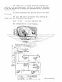
Access to Instruments
~·1:-----------------------~ ::;;'
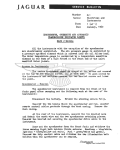
The centre instrument panel i s hinged at the bottom and secured
at the top by two knurled screws, one at each end.
To gain access to
the instruments and switches unscrew the two knurled screws and lower
the panel.
Speedometer - Removal
The speedometer instrument is removed :tram the front of the
:facia panel after carrying out the following rork at the rear of' the
instrument:Disconnect the battery.
Extend the steering coluon fully.
Unscrew the two bezels where the speedometer and rev. counter
remote control cables protrude through the dash casing.
Remove the
dash casing.
At the rear of the instrument, unscrew the two knurled nuts
and detach the earth wire and the two speedometer retaining pieces.
Unscrew the knurled nut securing the speedometer drive cable to the
instrument.
Draw out the speedometer from the front :facia and wi. thdraw the
three warning light bulb holders (Cable colours: Headlamp - blue/l'lhite,
Ignition- browr;V'yellow and white, Fuel - greell/white and green).
Unser~ the trip control cable and withdraw the two illumination bulb
holders when the speedometer can be removed.
/Continued.
Jaguar Cars Limited 2005
Revolution Counter - Removal
It will be found advantageous to first renx>ve the speedometer
instrument as described in the previous paragraphs.
At the rear o'f the instrument unscrew the two knurled nuts and
deta.eh the earth wire and the two revolution oounter retaining pieces.
Unscrew the reroote control of the electric clock and detach the
"snap-on" cable connection (Cable colour - brown).
i.'i ithdraw the 'tYro
illumination bulb holders and detach the "sna,P-on" cable connection for
the revolution counter (Cable colour - black/blue and black/brown) •
The revolution COWlter can now be w:i. thdra\vn.
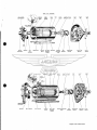
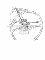
Testing Operation of Revolution Counter
The only testing of this unit is with the engine ticking over.
Place an J£ vol"bneter on the terminals of the generator at the rear of
the right-hand. ca.mshat't, when a current should be recorded.
As a rough
guide, there should be a 1 volt output per 100 revs.
Should the generator record a voltage output, due to its construction it can be
assumed that it is :f\mctioning accurately.
Should the revolution
counter instrument not then £'unc tion it must be r epl aced.
When the overdrive is in operation the word "Overdri ve 11 in the
quadrant behirid the steering wheel becomes illuminated; when the sidelights are switched on the illumination is automatically dimmed.
AU'l'Q;1ATIC TRANSMISSI<li INDIL.:AT<R LIGHT
'IVhen the ignition is switched on the letters P.N.D.L.R. in the
quadrant behind the steering wheel b ecome illuminated; when the sidelights are switched on the illumination is automatically dinmed.
Jaguar Cars Limited 2005
JAGUAR
SERVICE BULLETIN
Number
Section
Sheet
Date
P.2
Electrical and
I nstruments
1 (of' 1)
Januacy, 1960
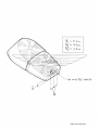
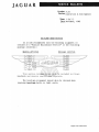
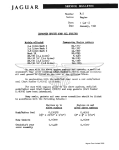
DRAIN HOLES IN NEW TYPE REAR LA11PS
Models affected
Cars with new type tail lamps
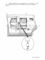
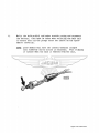
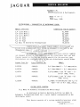
A certain number of' 1 960 oars with the new type rear lamps
(with separate flasher and tail light bulbs) were sent out of the
factory without the drain holes in the bottom of the lamp lens.
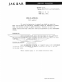
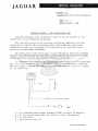
Cars in stock or cars ooming in for servicing should be
ch:ecked for having two noles drilled in the bottom of the rear lamp
lens.
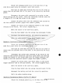
If not so drilled, two hol e s should be made in the bottom o f
the lens as sho~ in the sketch overleaf.
Jaguar Cars Limited 2005
1
y,d
=
-Ys
=
9· 5mm
}32
=
2· 5mm
II
6 · 3 mm
TWO HOI ES 3/J2" DIAMETER
lu
/4.
Jaguar Cars Limited 2005
_jAGUAR
SERVICE BULLETIN
Number
Section
Sheet
Date
P.3
Electrical and
Instruments
1 (of' 1 )
Ja.nu.ary, 1960
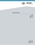
on. PRESSURE GAUG-E - LON INDICATED READmG
Mark 2 Models
I1' it is suspected that the
gauge is rea:ting low, 9.. normal type
ected to the lubrication system and
taken on the two gauges at the same
electrically operated oil pressure
of pressure gauge should be conncomparative pressure readings
engine speed.
This is mc.-,t easily done by using an oil gauge pipe union
(Part number 2698) brazed to a banjo bolt (Part number 0.5846) through
the head of which an ~~~ hole has been drilled.
This adaptor can then be screwed into the cylinder block in
place of' the existing banjo bolt f'or t he oil feed pipe to the camsha:fts.
A nonnal oil pressure gauge oan then b e connected to the adaptor and the
gauge reading compared with the electri cally operated instrument.
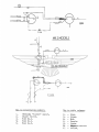
niACCURA.CY OR FLUCTUATICfi OF FUEL GAUGE AND WATER TEMPERATURE
GAUGE READDTGS CCNSISTmT WI'm mfGINE SPEED
Mark 2 Models
Mark 2 models are fitted with an instrument volta.ge control
unit which reduces the battery voltage to 10 volts for the fuel gauge
and water tem_t>erature gauge.
I:f oomplaints are reoeived of inaccuracy or :fluctuation with
engine speed with either of these gauges check the following points before changing the instrument or operating element.
1•
Check voltage oontrol unit for a good ''earth 11 •
earthed to the panel by the mounting screw.
The unit is
2.
Cables inoorrectly connected to voltage control unit.
should be oonnected as follows:-
The cables
/Cont 1 d •••
Jaguar Cars Limited 2005
Terminal 'B' = Dark
Terminal
}.
1
I'
~een
= Light green with dark green tracer.
Faul.t.Y instrument voltage control unit.
This can be checked
b,r shorting out the 'B' and 'I' tenninals on the unit when, if'
there is no change in the petrol gauge reading the unit can be
assumed to be :fauJ.ty.
The instrument panel voltage control unit is attached to the rear
of' the instrument panel between the oil pressure and water temperature
gauges.
To gain access to the rear o:f the instrmnent panel unscrew the
two knurled screws at the top of the panel and lower the panel which is
hinged at the bottom.
Jaguar Cars Limited 2005
JAGUAR
SERVICE BULLETIN
P.4
Number
Electrical and
Instruments
1 (of 1)
Section
Sheet
March, 1960
Date
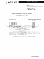
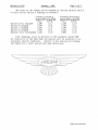
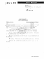
60 lb per sg. in. OIL PRESSURE GAUGE
Yodels affected
Commencing Chassis numbers
R.H. Drive
L.H. Drive
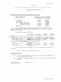
2. 4 litre Mark 2
1 0141+6
3.4 litre Mark 2
3. 8 litre Mark 2
151003
200668
125370
175499
211867
On cars with the above chassis numbers and onwards an oil
gauge reading up to 60 lbs per sq. in. is fitted in place of a gauge
reading up to 100 l bs per sq. in. ; in conjunction with this change a
different operating element is fitted tO the oil filter head.
The
part numbers are as foll ows:-
Part number
Oil pressure gauge (60 lbs per sq. in.)
Electric operating element
0.15473
0.15474
Servicing Procedure
Only the above parts will in future be supplied :f'rom the Jaguar
Spares Department and when the 60 lb gauge is used to replace the 100 lb
gauge (Part number 0.15913) the appropriate element (Part number 0.15474)
~
be fitted to the oil filter head.
Similarly, if it is found
necessary to replace the operating element (Part number 0.15914) fitted
in conjunction with a 100 lb gauge, a 60 lb oil pressure gauge must also
be fitted.
Note:
Vfhen checking for a suspected low indicated oil pressure as
described in Service Bulletin P.3 it is advisable to maintain
an engine speed of 2,500 r.p.m. f'or a period of 2t minutes to
obtain the true oil pressure reading on the electrically operated
oil gauge.
Jaguar Cars Limited 2005
JAGUAR
SERVICE
BULLETIN
Number
Section
P.5
Sheet
Date
Ele ctrical and
In.struments
1 (of 1)
May, 1960
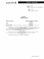
HOBN RING COVER CLIPS
(Mark 2 Models)
In the event of breakage of the spring clip s which secure the
horn ring cover to the horn ring centre, new clips (Part number 834 2)
should be fitted ai¥1 fixed into position using an epoxy resin type of
adhesive such as n Araldi te" ( 1000 A and B) which is readily available
from ironmongers, factors etc.,
This product is marketed in the
u.s. A.
by:Ciba Product s Corporation,
Fairlawn,
New J ers ey,
U.S.A.
Carefully remove the damaged clip with a pair of pliers and
clean out all traces of the old adhesive hom the spring clip recess e s
in the plastic moulding.
When f i tting the new spring clips into their
recesses follow the instruct ions supplied with the adhesive.
Jaguar Cars Limited 2005
JAGUAR
SERVICE
BULLETIN
Number P. 6
Section Electrical and
Instruments
Sheet 1 (of l)
Dat~
February , 1961
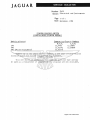
INTRODUCTION OF C48 DYNAYO
(Yark IX cars for U. S.A. and Canada)
(Special orders for other L.H. Drive countries)
Commencing Chassis Numbers
R.H . Driv e
Yark IX
L.H. Drive
793734
Cars for U.S.A. and Canada on and after the above chassis
n umber s are fitted with a higher output dynamo (Part number C.l646l).
The introduction of thi s dynamo
fo llowing:-
necess~tates
changes to the
Co ntrol box
35 amp setting (Part number C.l6465)
Dynamo mountings
Fan belt
(Part number C.l6395)
Ammeter
(Part number C . l6893 )
Power-assisted steering hose - to suit lower position of dynamo
Hole in front wing valance repositioned - to suit lower position of
dynamo .
Power assisted pump - to suit lower position of dynamo .
For full details of the new parts involved in this change r efer
to Spares Bulletin numbers A.45, Y.8 , P.29 and Q.l9.
Jaguar Cars Limited 2005
JAGUAR
SERVICE
BULLETIN
Number P. 7
Section Electrical and
Instruaents
Sheet 1 (of 1)
Date June, 1961.
OXIDIZATION OF DISTRIBUTOR AND REGULATOR CONTACTS
(All llode1&)
Oxidization of the distributor points and regulator contacts
can occur on a car which has been stored for a long period. Aa
a result difficult starting or failure to start the engine, together
with charging trouble may be experienced.
It is, therefore, advisable to clean both the distributor
and regulator contacts before atteapting to start the engine of a
vehicle which has not been used for some ti•e.
Jaguar Cars Limited 2005
JAGUAR
SERVICE BULLETIN
Number P. 9
Section Electrical and
Instruments
Sheet 1 (of 1)
Date January, 1962
HEATER MOTORS
("E" Type)
It should be noted that the heater motors fitted to the
nE" Type models are of A.C.-Delco manufacture and any correspondence
relating thereto should be addressed to : A.C.-Delco Division of General Motors Ltd.,
Watling Street,
Dunstab1e,
Bedf ordsh i r e.
REVOLUTION COUNTERS WITH UARK 11
Models affected
~OVEWENTS
Commencing Chassis Number s
R.H. Drive
L.H. Drive
2.4 litre Mark 2
Standard Transmission
Automatic Transmission
Overdrive
110821
110803
110791
126600
126597
126598
3.4 litre Mark 2
Standard Transmission
Automatic Transmission
Overdrive
157655
157978
157955
177633
177658
177645
3.8 litre Mark 2
Standard Transmission
Automatic Transmission
Overdrive
206743
206924
206930
218592
219046
219028
"E" Type
Open 2-seater
Fixed Head Coupe
850289
860029
876117
885206
On cars with the above chassis numbers and onwards, a
rev. counter with a modified movement (»ark 11) is fitted. On
/Continued overleaf ..•
Jaguar Cars Limited 2005
... - ·
''E" Type cars this instrument is interchangeable with the Mark 1
instrument but on Mark 2 cars the instruments are NOT interchangeable.
When ordering a replacement rev. counter, the code numbers
on the instrument face must be quoted.
Spares Bulletin Number
~.28
refers.
Jaguar Cars Limited 2005
JAGUAR
SERVICE BULLETIN
Number P .10
Section Electrical and
Instruments
Sheet 1 (of 1)
Date February, 1962
INTRODUCTION OF C.48 HIGH OUTPUT DYNAMO
(3.4 and 3.8 litre Mark 2)
A high output dynamo has been introduced as OPTIONAL EXTRA
equipment on 3.4 and 3.8 litre Mark 2 Models. This dynamo is not
interchangeable with that fitted as standard equipment.
Spares Bulletin Numbers A.73, L.l7, and Q.29 refer.
Jaguar Cars Limited 2005
JAGUAR
SERVICE
BULLETIN
Number P.14.
Section Electrical and
Instruments
Sheet 1 (of 2)
Date April, 1962
ELEC'IRICALLY-HEATED BACKLIGIIT
An electrically-heated backlight to provide demisting or
defrosting has been introduced as an optional extra on all current
production models except the Open 2-seater "E" Type.
A heating element consisting of a fine wire mesh between the
laminations of glass is connected to the wiring harness.
The .element
will come into operation when the ignition is switched on; the
current consumption being approximately 5 amps.
Tinted (Sundym) glass is obtainable at an additional cost.
Mark 2
Parts required
BD.21942
BD.,22742
C.20125
80.11524
80.,22655
BD. 711/5
==~~ Description
~ Backlight (Clear Glass)
Backlight (Sundym)
Fuse Connector and Cables
Gr~et
c.s204
80.1229/7
Clip for Fuse Holder
Screw securing Clip
Earth Terminal
Self-tapping Screw
No. off
1
1
1
2
1
1
1
1
Fit the fuse retaining clip (BD.22655) adjacent to, but below
the present fuse block on the left hand wing valance.
Connect the white
cable from the fuse connector (C.20125) to the terminal A3 with existing white cables.
Lead the blac~white cable along with the present
harness into the instrument panel, and across to the left hand body
harness junction.
Lead the cable down the left hand door sill into
the luggage compartment.
If difficulty is experienced in passing the
cable through the door sill, it is penmissible to place it under the
carpet on the interior of the car.
Remove the original backlight, drill two ~' (9.5 mm) holes
12" (30.48 ern) from either side of the centre of the backlight and !i"
(12.7 rnrn) below the lower edge of the glass.
Place the two grommets
(BD.11524) in position.
Pierce two holes through the glass rubber surround and pass
/Continued
Jaguar Cars
Limited 2005 •••
...
the heated backlight cables through.
Fit the backlight (BD.21942 or BD.22742) as described on page
M.14 and 15 of the Mark 2 Service Manual.
Take care to push the cables
into the interior of the c ar when fitting the glass.
Pass the cables
through the rubber grommets into the luggage compartment and connect
the black/white cable to its counterpart.
The black cable from the
heated backlight should be ·fitted with earth terminal (C.5204) and earthed
at a suitable point near the cable.
Mark 10
Parts required
BD.21857
BD.22743
c.19724
C.20128
BD.22655
BD. 711/5
c.15639
C.1 ()4()/13
UFS.419/4H
UFN.1 19/L
C.723/A
Description
No. off
Backlight (Clear Glass)
Backlight (Sundym Glass)
Fuse Connector and Cables
Bracket for Fuse Holde r
Clip for Fuse Holder
Screw, securing Clip
Gromnet
Cable Clip
Setscrew securing Cable Clip
Nut on Se t screws
Washe r under Nut -=::;:::"':=:::::::=:=--
1
1
1
1
1
1
2
2
2
2
2
On Mark 10 models t he feed wi re to the heated backlight is
incorporated in the harness.
Remove the two knurled nuts and hinge
down the instrument panel.
Release both fuse blocks on the left hand
side and slide the bracket (C.20128) over the studs.
Retain the
bracket by refitting the fuse bl ocks .
Fi t the fuse retaining clip
(BD.22655) to the bracket with t he aid of t he self-tappping screw (BD.
711/5).
Place the fuse connector and cables (C.19724) in the clip
already fitted and connect the white cable to t he terminal block at
which all other white cables are collected.
Connect black/white
cable from fuse holder to equivalent cable already situated in the
original harness.
Drill two~" (6.35 mm) holes 12~" (31.1 em) from e i ther side
of the centre of the backlight aperture and ~n (9.52 nm) from the
rear edge of the parcel shelf.
Fit the two grommets (C.15639) in
the holes drilled in the parcel shelf.
Pierce two holes in the
glass surround rubber and pass the black/white and black cables through
the rubber.
Fit the heated backlight (BD.21857 or BD.22743) as already
described under Mark 2 fitting instructions.
Pass the cables through
the parcel shelf and into the luggage compartment.
Drill two 7/32"
(5.55 mm) holes into the underside of the parcel tray approximately
3 11 (7.62 em) from the holes already drilled.
Secure cables with clips
Jaguar Cars
/Continued
•••Limited 2005
Service Bulletin No.
P.14.
continued
Sheet
2 (of 2)
(C.1040/13) to the underside of the parcel tray with the setscrews, nuts
and washers provided.
Join the blac~white and black cables to their
equivalent in the rear harness.
"E" Type
Parts required
BD.22629
BD.22741
C.20124
c.2o123
c.15639
c.ts341
BD.22655
BD. 711/5
c.2oos1
c.11001
c.11002
Description
Backlight (Clear Glass)
Backlight (Sundym Glass)
Fuse Connector and Cables
Backlight connector Cables
Gronrnet
Gronrnet
Clip for Fuse Holder
Screw securing Clip
Sail Eyelet and Ring
P.V.C. Strapping (3~" long)
Stud
No. off
1
1
1
1
2
3
1
1
1
2
2
Lower the instrument panel and fit the fuse retaining clip
(BD.22655) to the lower edge of the right hand lower fuse block.
Place the fuse connector (C.20124) in the clip provided and connect t he
white cable to the terminal bl ock whe r e all white cables are collected.
Lead the blac~white cable from t he fus e connector down the left hand
door sill following the r ea r harness, to t he cover ed aperture provided
in the left hand rear quarter tail casing.
Dril.l two~~~ (6.35 nrn) hol es 18" (45.72 em) apart from the
centre of the backlight.
The hol es should be drilled parallel to
the backlight glass to enter between the inner and outer skins of the
boot lid.
Insert the two grommets (C.15369) in the holes drilled.
Pierce two holes 18'' ( 45.72 em) apart in the backlight rubber
surround and pass the blac~white and black cables through the rubber.
Fit the heated backlight (BD.22629 or BD.22741) as detailed
on page N. 19 of the "E" Type Service Manual.
When fitting the backlight, take care to keep the cables inside the car.
Pass the cables
through the two grommets in the rear panel and fit the backlight
connector cables (C.20123) to the black/white and black cables from
the backlight heating element.
Drill. a 7/1611 ( 11. 11 mm) hole adjacent to the lower door hinge,
insert the sail eyelet and ring, and pass the cables out through this
aperture.
Strap the cables to the lower door hinge and pass through
another 7/16" {11.11 nm) hole drilled in the left hand quarter tail
casing approximately 2J&" (5.40 mm) to the rear of the lower hinge and
~~~ (5.71 nm) from the top of the quarter tail casing.
Connect the
/Continued
•••2005
Jaguar Cars Limited
blac~white
cable to its equivalent situated in the aperture in the
rear quarter.
The interior light earth snap connector is changed to
a double connector and the black cable from the heated backlight is
inserted to provide an earth.
Jaguar Cars Limited 2005
JAGUA .R
SERVICE
BULLETIN
Number P.l4. (2nd is s ue)
Section Electrical and Instruments
(
Sheet 1 ( of 3)
Date December, 1962.
This Service Bulletin supersedes the original issue of April 1962
which should be destroyed.
ELECTRICALLY-HEATED BACKLIGHT.
An electrically-heated backlight to provide demlsting or
defrosting has been introduced as an optional extra on all current
production models except the Open 2 - seater 'E' Type.
The heating element, consisting of a fine wire mesh between
the laminations of the glass, is connected to the wiring harness.
The heating of the element will come into operation when t he
ignition is switched on, the current consumptron being approximately
5 amps, and a 15 ampere fuse i s incorporated in the circuit.
Tinted (SUNDYM) glass is obtainable at an additional cost.
MARK 2 MJDELS
Parts required
BD 21942
BD 22742
c 20125
BD 11524
BD 22655
BD 711/5
c 5204
BD 1229/7
No. off
Description
Backlight (Clear Glass)
Ba~klight (SUNDYM)
Fuse Connector and Cable
Gromnet
Clips for Fuse Holder
Screw securing Clip
Earth Tenninal
Self-tapping Screw
1
1
1
2
1
1
1
1
Fit the fuse retaining clips (BD 22655) adjacent to, but, below
. the fuse block on the left hand front wing valance. Connect the
white cable from the fuse connector (C 20125) to the terminal A3
on the fuse block along with the existing white cables.
Tape the blac~white cable into the panel harness and lead
across to the left hand body junction.
/cont'd ••••••••
Jaguar Cars Limited 2005
Feed. the cable along the l eft hand door sill with the body
r e ar harness and terminate in the luggage compartment.
If difficulty is experienced in passing t he cable through the
door sill it is permissible to place it under t he carpet.
Remove the original backlight as detailed i n the Mark 2
Se rvice Manual - page N 14.
Drill two ~' (9.5 lllll) holes 12" (30.48 em) either side of the
centre line of the backlight and~~~ (12.7 mm) below the lower edge
of the glass on the inner body panel. Place t he two grommets
(BD 11524) in position.
Pierce two holes in the inner face of t he glass r ubber
surround and pass the heated backlight cables through into the body.
Fit the backlight (BD 21942 or BD 22742) as described on
page N 14 of the Mark 2 Service Manual.
Pass the cables through the rubber grommets into the luggage
compartment and connect the black/white cable to its counter part
previously i nstalled. The black cabl e f r om the backlight should be
fit ted with earth terminal (C 5204) and earthed to a suitabl e point
nea r the cable.
MARK 10 1\'DDEL
Parts required
BD 21857
BD 22743
c 19724
c 20128
BD 22655
BD 711/5
c 15639
c 1040/13
UFS 419/4H
UFN 119/L
C 723/A
Description
No off
Backlight (Clear Glass)
Backlight (SUNDYM)
Fuse Connector and Cables
Bracket for Fuse Holder
Clip for Fuse Holder
Screw, securing Clip
Grorranet
Cable Clip
Setscrew securing Cable Clip
Nut on setscrew
Washer under Nut
1
1
1
1
1
1
2
2
2
2
2
On Mark 10 models the f eed wire to the heated backHght is
incorporated in the harness . Remove the two knurled screws and
hinge down t he instrument panel.
/ cont'd •••••••••
Jaguar Cars Limited 2005
Service Bulletin No. P.l4 2nd issue
continued
sheet 2 (of 3)
Release both fuse blocks on the left hand side and sl ide the
bracket (C 20128) over the studs. Retain the bracket by refitting
the fuse blocks. Fit the fuse retaining clip (BD 22655) to the bracket
with the aid of the self tapping screw (BD 711/5).
Place the fuse connector and c ables (C 19724) in the clip and
connect the white cable ·to t erminal A3 on the fuse block along with
the existing white cables.
Connect the blac~white cable from the fuse holder to the
equivalent cable already situated in the existing body harness.
Remove the rear backlight as detailed in the Mark 10
Service Manual- page N 15.
Drill two 4" (6.35 mm) holes 12~" (31.1 em) from either side
of t he centre of the backlight and ~~ (9.5 mm) from the rear edge
of the parcel shelf. Fit the two grorrvnets C 15639 in the holes
drilled i n the parcel shelf.
Pierce hvo holes i n the glass rubber surround and pas s the
backlight cables through int o t he body.
Fit the backlight BD 21857 or BD 22743 as detailed in the
Mark 10 Service Manual - page N 15 .
Pass -che cables thr ough t he parcel shelf and into the luggage
compartment . Drill two 7/32" (5 . 55 rrvn) holes into the underside of
the parcel tray approximately 3" (7.62 em) from the holes already
drilled. Secure the cables with clips to the underside of the
parcel tray with the setscrews, nuts and washers provided. Join the
blac~whi te and black cable s to their equivalent in the rear harness.
'E' TYPE
Parts required
Description
No off
BD 22629
Backlight (Clear Glass)
1
(From Car No.860001 - 860478 (RHO) and 885001 -886013 (LHD)
BD 2274{)
Backlight (Clear Glass)
1
(From Car No.860479 onwards (RHD) and 886014 onwards (LHD)
BD 22741
Backlight (SUi\'DYl\'1)
1
(From car No.860001 - 860478 (RHO) and 885001 - 886013 (LHD)
BD 22744
Backlight ( SUi\'DYri'I)
1
(From Car No.860479 onwards (RHD) and 886014 onwards (LHD)
c 20124
Fuse Connector and Cables
1
c 20123
Backlight connector Cables
1
c 15639
Grommet
2
Jaguar Cars Limited 2005
/cont'do••••••
'E' TYPE CONT'D.
Parts required
De scription
:'-Jo of'f
I
BD 22655
BD 711/5
c 17001
c 17002
c 18341
Clip for Fus e holder
Screw securi ng Clip
P.V.C. Strapping (3J2" l ong )
Stud
Grommet
1
1
2
2
l
Lower the instrument pane l and fit the fuse retain.ing c l i p
(BD 22655) to the lower edge of t he right hand fuse bloc!,.
Place the fuse connec tor (C 20124) in the clip and connect
t he white cables to t e rminal A3 a l ong with the e xi s ting white c able s.
TaJm t he c onnector cable i nto the pane l h a rness and lead across
to the left hand sideo
Feed the cabl e along t he l e f t hand door sJll f ollowing the r un
of t he left hand rear body harness and t erminate t n t he l eft hand r ear
quarter.
Remove the left hand rear quarter casing aperLur e cover
and locate the rear window harness .
Connect the black (earth) c able Logethe r with t he interior
light earth CCibl e u ~ing the double snap connector supplied .
WARNI NG
Do nol atte mpt to lift the "lrimning completely from
the door s ill. Ra ise the lower port ion only and
r oute the cable under the l eathe r c loth.
Ease t,he r e ar quarter casing away from t he pane l.
Insert grommet (C.1834 l) .i n the J2" hole l oc a t ed adjacent to the
lower hinge broc ke t. Pass t he cable harness t hrough the gromme t and
clip Lo the lowe r hinge using t he P.V.C . s t!' apping (C 17001 and
s t uds Cl7002).
Refit r ear qua rter cas.i.ng .
Remove t he rear backlight a s detailed i n the 'E' Type Se rvice
Manual - page N 19.
Drill t wo 4" (6.35 rrm) holes 9" (22.8 em) e llher s ide of t he
centre line of t he bac kLight on t he lower edge of t he aperture . The
h ol es should be dr i lled parallel t o the glass to e nter betwee n t he
inner and outer pane ls of the lid.
Cars Limited 2005
/ cont 1 ( 1 • • • • • •Jaguar
•••
I
I
I
Service Bulletin No. P.l4 2nd issue
continued
sheet 3 (of 3)
I
/
NOTE:
Some early backlight glasses to Part No's BD 22629
and BD 22741 may be supplied with the cable connectors
protruding from the t op of the glass .
In this case drill t he two ~~~ holes i n the UPPER
edge of the ape rture and feed the extende d cables inside
the door frame to the l e f t .
Pierce two holes through the glass rubber surround and pass
the cabl e s through into the luggage compartment lid.
Fit the backlight BD 22629 - BD 22740 - BD 22741 or BD 22744
as deta iled in the 'E' Type Service Manual - page N 19. When
fi tting take care to keep the cables inside the car.
Remove the l i d stay and rubbe r c lip mountings and prise away
the door casing from the lower clip f i xings.
Pass the body connector cables under the casing and connect
to the backlight cables.
Refit casing, stay and rubber c l i p mountings .
~
•
Jaguar Cars Limited 2005
JAGUAR
SERVICE
BULLETIN
Number P.15.
Section Electrical and
Instruments
Sheet 1 (of 1)
Date May, 1962
RADIO FITTING INSTRUCTIONS
( "E" Type)
The attention of Distributors and Dealers is drawn to the
following points when fitting the Smiths Radiomobile.
It is most important when fitting the radio receiver, to remove
any felt material in the area behind and underneath the r eceiver heat
sink to assist in ventilation.
It may also be necessary to trim the
carpet to assist in clearing the heat sink.
When connecting the twin loudspeakers, it is important for the
terminal with the rubber sleeve to be fitted to the top screw terror
i nation of each loudspeaker.
Thi s will ensure that the speakers are
connected to operate in anti-phase giving the correct tone.
FOGLAMP FITTING INSTRUCTIONS
(Mark 10 Model)
Twin rectangular foglamps with yellow bulbs are now available
for fitting to the Mark 10 model as optional extras.
Parts required
C.20443
C.20246
C.15447
C.15463
C.2706
C.1426
C.20444
c.z~
c. 17001
C.17002
Description
Foglamp
Lighting switch (4 position)
Escutcheon
Foglamp connector (cable)
Grorrmet
Grommet
Foglamp bracket L.H.
Foglamp bracket R.H.
Cable strapping
Stud
No. off
2
2
2
2
1
The foglamp brackets should be bolted to the bumper utilizing
the two inner bumper bracket bolts.
The foglamps are fitted to the
brackets and are positioned under the bumper on the inside of the
/Continued •••
Jaguar Cars Limited 2005
overriders.
On later cars, a hole is provided in the front cross
member cover plate adjacent to the bumper bracket, and the foglamp
connector cable should be passed through utilizing a grommet.
Early cars will require a hole drilled in the front cross
member cover plate as shown in the illustration.
Feed the cable through the 1~" hole utilized by the radiator
drain tap on the left-hand side, and the corresponding hole on the
right-hand side,
Place the large grommet in the aperture to prevent
the cable from chafing.
Connect the left-hand foglamp cable to the red/yellow cable
incorporated in the wiring harness, which is situated at the top of
the wing valance in line with the front of the engine.
The red/yellow cable for connection to the
Remove the
the air cleaner intake box.
Remove the two quick
and withdraw the paper element.
Pass the foglamp
of the air cleaner intake trumpets.
will be found behind the air cleaner.
r i ght-hand foglamp
flexible hose to
release fasteners
cable through one
Clip the foglamp cables to the bumper brackets with the-a id
of the cable strapping,
Remove the original lighti ng swi t ch and escutcheon and replace
with the four position switch and a new escutcheon plate.
Replace the cables in their original positions and connect the
r eq/yellow cables, incorporated in the harness, to the foglamp terminal.
The foglamps and necessary parts are available from the Jaguar
Spares Division, Coventry.
Spares Bulletin number Q.39 refers.
SLOT FOR BUMPER
BRACKET
~
2 H OLES
1'
4
(i9 · 0MM)
Jaguar Cars Limited 2005
JAGUAR
SERVICE
(
BULLETIN
Number P .15. ( 3rd issue)
Section Electr ical and Instruments
Sheet 1 ( of 1
Date January, 1963.
This Service Bulletin supersedes the 2nd issue of July 1962
which should be destroyed.
RADIO FITTING INSTRUCTIONS
(All mode l s fi t ted wit h trans ist or radios)
The attention of Distributors and Dealers is drawn to the
following points when fitting the Smiths Radiomobile .
It is most important when fitting the radio r eceiver , to
remove any felt material in t be area behind and underneath the receiver
heat sink to assist in ventilation. It may also be necessary to trim
the carpet to assist in cleari ng the heat sink.
When connecting the twin loudspeaker s, it is important fo r the
terminal with the rubber sleeve to be fitted to the top screw
termination of each loudspeaker . This will ensure that the speakers
are connected to operate in anti-phase giving the correct tone .
FOGLAMP FITI'ING INSTROCTIONS
(Mark 10 Mode l)
Twin rectangula r foglamp s with yellow bulbs ar e now available
for fitting to t he Mark 10 mode l as optional extras.
Parts required
Desc ription
C.20443
Foglamp
Light ing switch (4 position)
Es cutcheon
Foglamp connector ( cable )
Grolllllet
Fogl amp bracket L.H.
Fogl amp bracket R.H. ·
Cable s trapping
Stud
c .20246
C.l5447
C.l5463
C.2706
c. 20444
C.20445
C.l7001
c .17002
No off
2
1
1
2
4
1
1
12"
2
1 2005
Jaguar Cars
Limited
/ cont
d ••••••
The foglamp brackets should be bolted to the bumpe r utilizing
the two inne r bumper bracket bolts. The foglamps are fitted to the
brackets and are positioned under the bumper on the inside of the
overriders. On later cars, a hole is provided in the front c ross
member cover plate adjacent to the bumper bracket, and the foglamp
connector cable should be passed through utilizing a grommet.
Early ca rs will r equire a hole drilled in the front cross
member cover plate as shown in Fig.l.
It will be necessary to drill a ~" (19. 05 mm) hole inside
the engine compartment adjacent to the radiator drain tap aperture
and a corresponding hole on the opposite side of the radiator. The
holes should be drilled 211 (5.08 em) from the outer edge of the
longitudinal underframe member and ~" (19.05 mm) from the radiator
support panel . Fit the grommets provided and pas s the f oglamp cables
thr ough the grommets into the engine compartment.
Connect the left- hand fogl amp cable to the req/yell ow cable
incorporated in the wiring harness, whi ch i s s ituated at the top
of t he wing valance in line wi th the front of the engine.
The red/yellow cable for connection to the right-hand foglamp
will be found behind the air cleaner. Remove the flexible hose to
the air cleaner intake box. Remove the two quick release fasteners
and withdraw the paper element. Pas s the foglamp cable through the
grommet adjacent to t he top air cleaner intake trumpe t.
Clip the foglamp
of the cable strapping.
cables ~o
the bumper bracke ts with the aid
Remove the original lighting switch and escutcheon and replace
with the four position switch and a new escutcheon plate.
Remove the printed circuit resistance from the original switch
(te rminals 2 and 11) and refit to the new switch (te rminal 2 - 4)
Fit the resistance with the large hole over the centre post and
the printed circuit to the switch back pl~t e .
Replace the cables as shown in Fig.2. and connect the red/ yellow
cables, incorporated in the harness, to the foglamp terminal.
The foglamps and necessary parts are available from the
Jaguar Spares Division, Coventry.
Spares Bulletin No. Q.39. refers.
Jaguar Cars Limited 2005
SLOT FOR BUMPER
BRACKET
~
2 HOlts
l"
..
(iCJ . OHM)
Frc.l
)2400)
1•
2.
3.
4.
s.
6.
7.
Green (Automatic) yellow/purple (Overdrive)
ReQ/black (Sidelights and taillights)
Black/red (Warning light - automatic or overdrive)
Brown/white (Ammeter)
ReQ/yellow (Foglamps)
Blue (Headlamps)
Jaguar Cars Limited 2005
JAGUAR
SERVICE
BULLETIN
Number P.l9.
Section
Electrical and Instruments.
Sheet _l ( of 1 )
Date December, 1962.
EXAMINATION OF SPEEDOMETER CABLE OIL SEAL.
(Current Production Overdrive Models).
It has been noticed that speedometer heads are being changed
due to excess oil entering the mechanism. When a car is received
in Service with this complaint, ,it i s advisable to examine the oil
seal contained in the bronze bus h of the speedometer cable drive
gear contained in the overdrive rear casing .
If oil is found to be working along the c able, it will be
necessary to change the complete driven gear bush.
ELECTRICALLY OPERATED WINDOWS - LIMITTED BACKLASH COUPLING
(Ma rk 10 Model)
This bulletin should be used in conjunction with the information
given in Service Bulletin Nos. P. l3 and 16 .
Cars now in production are being fitted with a new rubber
coupling (Part No. BD.20909) and driving peg (Part No. BD.25088) to
allow the electric motor to gain momentum before raisi ng or lowering
the wi ndow. (The rubber coupling is item 15 in Fig 53 on page P.43
of the Mark 10 Service Manual.
It will be necessar y to remove the complete regulator and motor
unit as described on page P.41, 42 and 43 of the Mark 10 Service
Manual.
Remove the motor from the regulator bracket and lift the
coupling off the "D" shaped shaft.
Fit the driving peg onto the "D" shaped driven shaft, then
place the rubber coupling with the lug fac i ng the bottom of the
regulator in position over the driving peg. The coupling should be
free to rota te on the driven shaft.
Replace the motor ensuring that the motor output shaft is
aligned correctly in the "D" shaped hole in the rubber coupling.
Replace the regulator assembly ensuring that t he directions
given in the aforementioned bulletins are closely followed.
Jaguar Cars Limited 2005
JAGUAR
SERVICE
BULLETIN
Number P.l9. (2nd issue)
Section Electrical and Instrwnents
Sheet 1 (of 1 }
Date January, 1963.
This Service Bulletin supersedes the original issue of
December 1962 which should be destroyed.
EXMITNATION OF SPEEDOMETER CABLE OIL SEAL
(Current Production Overdrive Models).
It has been noticed that speedometer heads are being changed
due to excess oil entering the mechanism. When a car is received
in Service with this complaint, it is advisable to examine the oil
seal contained i n the bronze bush of the speedometer cable drive
gear contained in the overdrive rear casing.
If oil is found to be working along the cable, it will be
necessary to change the complete driven gear bush.
ELECTRICALLY OPERATED WINDOWS - LIMITED BACKLASH COUPLING
(Mark 10 Model)
This bulletin shoul d be used in conjunction with the information
given in Service Bulletin No s . P.l3 and 16.
Cars now in production are being fitted with a new rubber
coupling (Part No. BD.20909) and driving peg (Part No. BD.25088) to
allow the electric motor to gain momentum before r a ising or l owering
the window. (The rubber coupling is item 15 in Fig 53 on page P.43
of the Mark 10 Service Manual.)
Remove the woodwork and trim panel from the door.
Remove the two setscrews on either side of the motor securing
the motor to the support plate.
Move the motor up from the regulator bracket sufficie ntly to
lift the coupling off t.he "D" s haped shaft.
Fit the driving peg onto the "D" shaped driven shaft, then
place the rubber coupling with the lug facing the bottom of the
regul ator in position over the driving peg. The coupling should be
free to rotate on the driven shaft.
Refit the motor ensuring that the motor output
shaft is aligned
Jaguar Cars Limited 2005
correctly in the .,D.. shaped hole in the rubber coupling.
/cont'd •••.••
Whilst carrying out this operation, it is advisable to treat
all the window felts with a siliconized fluid such as Duckhams
"Adsil".
Jaguar Cars Limited 2005
JAGUAR
SERVICE
BULLETIN
Number P.20.
Section Electrical and Instruments.
Sheet 1 (of 1 )
Date January, 1963.
REVOLUTION COUNTER AND CLOCK - SERVICING
(All current production models)
Distributors and Deale rs are advised that in future, Revolution
Counters will be supplied ONLY less Clock. Complete instruments
will, therefore, no longer be available, though the Electric Clock
will, of course, continue to be serviced as a separate item.
In all Guarantee Claims concerned with a faulty Revolution
Counter, the Electric Clock MUST be removed before the instrument
is returned to the factory . Similarly, if the Electric Clock is
faulty , this Unit ONLY mus t be returned to the factory for Guarantee
replacement.
All concerned are asked LO save the containers in which the
Revolution Counter or Electric Clock is packed, and to urge their
staffs to use these cartons when returning displaced units to the
factory. This will prevent transit damage.
It should be noted that this new procedure is EFFECTIVE
IMMEDIATELY and any complete instruments being received at these
Works after receipt of this Bulletin will be treated as requiring
attention to both the Revolution Counter and the Electric Clock even
though one or the other may be functioning correctly. In this case
full charge will be made for the a s sembled instrument.
Jaguar Cars Limited 2005
JAGUAR
SERVICE
BULLETIN
Number P. 21.
Section Electrical and Instrwnents.
Sheet 1 ( of 1 )
Date March, 1963.
HEADLAMP FLASHING
I~
THE FULL BEAM POSITION.
(Italian market cars only)
Models affected.
Commencing Chassis Numbers.
L.H.Drive.
2.4 litre Mark 2.
3.4 litre Mark 2.
3.8 litre Mark 2.
Mark 10.
'E' Type Fixed Head Coupe.
Open 2 seater .
127056
178968
222239
352199
888264
879067
Commencing at the auove chas sis numbers, all cars for the
Italian market will have the headlights wired to "flash" when the
lights are 11 off" or whe n t hey are in the main beam position: They
will not '' flas~ ' in the dipped position.
The amended wiring circuits are shown overleaf.
Jaguar Cars Limited 2005
uw
2
N
I
I
: _ _ _ _ l!R_ _ _ _
j
I,
1
c 22141
MK2 MODELS
uw
2.
UR
MK 10 MODELS
. ~- -·~(221<10
UY
/
/
'E' TYPE
uw
KeJ:: to illustration numbers.
1.
2.
3.
4.
s.
Headlamp "flasher" switch.
Dipper switch.
Fuse No.1.
Fuse No.2.
Fuse No.3.
Key to cable colours.
u.
N.
R.
P.
G.
w.
Y.
=
::-:
::::
;;;;
Blue.
Brown.
Red.
Purple.
Green.
White.
Jaguar Cars Limited 2005
Yellow.
JAGUAR
SERVICE
BULLETIN
Number P.22.
Section Electrical and Instrwnen ts.
Sheet 1 ( of 1 )
Date April, 1963.
INTRODUCTION OF MODIFIED DISTRIBUTOR.
;
·'
/
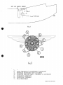
All current pr?fiuction cars are now fitted with a new 2206
type distributorl.iustrated overleaf)
This type f distributor is different in construction t
previous DMBZ6 t~ e fitted but the advanc~ curves remain the
the
The ne type distributo': are inte rchangeable with
appropriate P, edecessors providif~ a new type suction pipe ·s
. Rj
\\
fpares
/
i
r.. ·
,
I
I
I
and Q. 59 refer.
/
~
~
i
I
Jaguar Cars Limited 2005
DISTRIBUTOR MODEL 22 D6
C B. EARTH
CONNECTOR
L T TERMINAL
FIXED CONTACT PLATE
SECURING SCREW
CONTACT BREAKER
MOVING PLATE
CAM
CONTACT BREAKER
BASE P LATE
CENTRIFUGAL TIMING
CONTROL WEIGHTS
VACUUM TIMING
UNIT
CONTROL
Jaguar Cars Limited 2005
JAGUAR
SERVICE
BULLETIN
Number P .22 . ( 2nd I ssue)
Section Electrical and Ins truments.
Sheet 1 ( of 1 )
Date June, 1963.
This bulletin supersedes the previous issue of April 196 3 which
should be destroyed.
INTRODUCTION OF MODIFIED DISTRIBUTOR.
All current production cars are now fitted wit h a new 22D6
type distributor. (illus trated ove rleaf)
This type of dis tributor i s different in construction to t he
previous DMBZ6 type fitted but the advance curves remai n the same.
The new type dist ributors are interchangeable with t heir
appropriate predecessors prov i de d a new type-suction pipe i s fitte d.
Adjusting the Contact Breaker Points.
The method of adjust ing t he contact point is now diffe rent
to that described in the handbook and the following procedure should
be adopted:The correct gap i s
.01 411
-
.016'' (.36 mm- . 41 nm).
If the gap i s incorrect, slacken (very slightl y ) the c ontact
plate securing sc rew and adjust t he gap by turning a scr ewdrive r in
the slot in the contact plate (clockwi se to decrease the gap and anticlocbvise to increase the gap). Tighten the securing sc r ew and r echeck
the gap.
Spare s Bulletin No's. Q.53 and Q.59 r e f e r.
Jaguar Cars Limited 2005
OISTR I BUTOR MODEL 22 06
F\OTOR
L I
ARM------~
C.B EARTH
CONNECTOR
TERMINAL
CAPACIIOR
SECURING SCREW
CONIACT BREAKER
MOVING PLAIE
CAM
CONTACT BREAKER
BASE I"L..O.TE
CENTRl F U GAL TIMING
-.:ONTROL WE IGHT S
VACUUM TIMING CONTROL
U NIT
THRUST
WASHER
Jaguar Cars Limited 2005
JAGUAR
SERVICE
BULLETIN
Number P.23.
Section Electrical and Instruments.
1
Sheet 1 ( of 2)
Date April, 1963.
INTRODUCTION OF 1\I)DIFIED DYNAri{)S AND CONTROL BOXES.
(Mark 2 Models)
All current production Mark 2 cars are now equipped with a
di fferent type dynamo and control box. The illust rations show the
C.40L dynamo fitted to 2.4 litre cars and the C.42 dynamo fitted t o
3.4 litre and 3.8 litre cars.
The C.40L and the C.42 dynamo fitted to standard s teering cars
has a bush at the rear end of the dynamo which should be l ubricat ed
with engine oil through the hole ma rked "Oil" eve ry 5, 000 miles
(8,000km).
The settings f or the new dynamos and control boxes are given
below:2.4 LITRE .
C.40L
DYNAM)
Performance Data.
tq/
Cutting in speed.
Maximum output.
1250 r. p.m. (max .) at 13.0 dynamo volts.
25 amps at 2400 r.p.m. at 13.5 dynamo volts.
Field res i s tance.
6.0 ohms.
CONTROL BOX (RB 340) 37342 D.
Voltage Regulator (open cir cuit settings).
Ambi ent Temperature .
Voltage
10°C (50°F)
20°C (68°F)
30°C ( 86°F)
14.9 - 1 5 .5
14.7- 15.3
40°C ( 104°F)
14.3 - 1 4 .9
14.5 - 15 . 1
Cut -out Relay (settings).
Cut-in Voltage
Drop of Voltage
12.6 - 13.4
9.3 - 11.2
/cont 'd•••••••
Jaguar Cars Limited 2005
3.4 and 3.8 LITRE.
C.42 DYNAM>
Performance Data.
Cutting in speed.
Maximum output.
1,250 r.p.m. (max.) at 13 dynamo volts.
30 amps at 2,200 r.p.m. at 13.5 dynamo volts.
Field resistance.
4.5 ohms.
CONTROL BOX (RB 340) ( 37331A)
Voltage Regulator (Open Circuit Settings).
Ambient Terrnperature.
10°C (5o<>r)
2o0 c ( Bs<>r)
30°C (86~)
40°C (104~)
Voltage
15.0- 15.6
14.8 - 15.4
14.6 - 15.2
14 .4 - 15. 0
Cut-out Relay (Settings) .
Cut-in Voltage
Drop of Voltage
12 . 6 - 13.4
9.25 - 11.25
Spares Bulletin Nos. Q.52 and Q.56 refer.
Jaguar Cars Limited 2005
MOOEL C40l GENERATOR
CO~~UTATOA
FIBRE
END &RACKET
THRU-ST
YOK(
S~AFT
Sti-'F'T OJLLAR
OOI.J•.M
<;UP
S>W"T
KEV
WASHER
\
\
I
TERMtN41. •o•
BRUSHES
FELt
BEAP:ING
RE.TAINING
P'-"TE
'RI~C
REIAI HER
6AJ..L
COARVCA.TED
8EAFliNG
WASI-CER
\
DRJVE ENO
&RACIU::T
PULLE'I'
SPAC.[R
.IAGU~I
I
BRUSHES
&At.\. &E.ARING
TMRUST WA'&Mf.R
MODEL C42 GEN[RATOR
TH R.OUG~
30&..1S
POLE SHOE
.SEC.VRING
BEARING RETAINING
PLA1[
BAll
COARU(.A.T[O
DRIVE. £1-o10
PIJllE't'
&A RING
SCREWS
Jaguar Cars Limited 2005
JAGUAR
SERVICE BULLETIN
Number P.24.
Section Electrical and Instrwnents.
Sheet 1 ( of 1 )
Date April, 1963.
This Service Bulletin supersedes the information given in Service
Bulletin P.l9 Which should be endorsed "See Service Bulletin P.2~'.
EXAMINATIOO' OF SPEEDOMETER CABLE OIL SEAL.
~~urrent
Production Overdrive Models).
It has been noticed that speedometer heads are being changed
due to excess oil entering the mechanism. When a car is received in
Service with this complai nt , it is advisable to examine the oil seal
contained in the bronze bush of the speedometer cable drive gear
contained in the overdrive rear casing.
If oil is found to be working past the inner seal it will be
necessary to dismantle the driven gear bush as follows:Drill out the steel pin retaining the brass adaptor to the
phosphor - bronze bearing.
Unscrew the adaptor from the bearing by means of the flats
provided.
Remove the rubber seal from the recess in the bearing. Fit a
new seal (Part No. C.8773) so that the open end of the seal through
which the spring is visible, is facing the bottom of the recess of the
bronze bearing (See illustration overleaf).
Screw
If necessary,
(5.5 mm) deep
over and file
the adaptor into the bearing and fit a new retaining pin.
drill a new 1/16" (1.5 JTJn) hole not more than 7/32"
in the side of the bearing; fit a mild steel pin, peen
flush.
Jaguar Cars Limited 2005
Jaguar Cars Limited 2005
JAGUAR
SERVICE BULLETIN
Number P. 25.
Section Electrical and Instruments.
Sheet 1 ( of 1 )
Date Augus t, 1963.
I~TRODUCTION
OF NEW DIRECTION
INDICATOR/HEADL~W
FlASHER SWITCH.
Model affected.
Commencing Chassis Numbers .
R.H.Drive .
'E' Type Open 2 Seat e r
850726
861198
Fixed Head Coupe
L.H.Drive.
879551
888767
ColliJiencing at the above chassis munbers, a new direction
indicator/he adlamp fl ashe r switch (Part No . C. 21710) str ike r plate
{C. 22872 ) and s ec i al washe r s (C . 23008 ) ar e int r oduced to repl ace the
exi sting switc h.
The two special washers are used in conjunction with the
striker plate securing screws and s hakeproof washers and must be
positioned between the s t r i];(er plate and shake proof washers .
The new switch i s f ully int erchangeable with the earl ier
type provide d all t hree items menU.oned a bove are used.
Spares Bulletin No. Q.67 refers.
WATERPROOFING OF THE DISTRIBUTOR.
Models affected.
2.4 litre
3.4 lit re
3.8 lit re
1
E' Type
Mark 10
Commencing Engine Numbers .
Mark 2
Mark 2
Mark 2
BH. 9981
KJ. l073
LC. 6957
RA. 2290
ZA. 9238
·
Commencing at the above engine numbers, a waterproof rubber
cap (Part No. C.2607) is fitted over eac h of the six plug leads and
the H.T. lead where they enter the distributor cap.
These rubber c aps can be fitte d to earlier cars if desired.
Spares Bulle t i n
~o.
Jaguar
Q.66 r ef
e r sCars
. Limited 2005
JAGUAR
BULLETIN
SERVICE
Number P • 26 •
Section Electrical and Instruments.
Sheet 1 ( of 1
Date October, 1963.
INTRODUCTION OF "LIVE" HORN BUTTON.
Models affected
Commencing chassis numbers.
R.H.Drive.
2.4 litre
3.4 litre
3.8 litre
Mark 10.
Mark 2
Mark 2
Mark 2
L.H.Drive.
116114
127312
164402
231586
306489
179499
223 125
353182
Commencing wi t h the above chassis numbers the centr e horn
button is now "live" and can be used in addition to the horn ring to
operate the horns.
The Mark 2 steering wheel is now common with the Mark 10
wheel but certain individua l Mark 2 cars prior to the above munbers
were fitted with the Mark 10 wheel without a ''live" horn button .
Spares Bulleti n No. Q. 70 refers.
Jaguar Cars Limited 2005
JAGUAR
SERVICE
BUllETIN
Number P .27.
Section Electrical and I nstrllllents.
Sheet 1 ( of 1 )
Date November, 1963.
ELECTRIC TIJ\IlE CLOCK.
Models affected.
Commencing Chassi s Numbe rs.
R.H.Drive.
2.4 litre
Mark 2
115205
3.4 litre Mark 2
3.8 litre Mark 2
1 E 1 Type Open 2 seater.
'E' Type Fixed Head Coupe.
Mark 10
163007
230516
850702
861169
304482
L.H.Drive.
127141
179136
22 2555
879324
888543
352709
Corrrnenc i ng at the above chassis mrrnbers, t he electric time
clock fitted to t he revolution counter dial , i ncorporates a rectifier .
This is to reduce fouling of the contact points i n the clock.
If at any t i me the clock i s removed for serv1c1ng and
subsequent testing on the bench, I T I S MOST IMPORTANT that the feed t erminal
on the back of the clock is connected to the negative side of the battery
and that the outer casing of the c lock is positively earthed. Incorrect
connection of a rectified clock to the battery will instantly destroy the
rectifier.
Spares Bulletin No. Q.61 refers.
Jaguar Cars Limited 2005
JAGUAR
SERVICE BULLETIN
Number P.28.
Section Electrical and Instrtunents.
Sheet 1 ( of 1 )
Date .March, 1964.
IGNITION SUPPRESSION - HOME TRADE ONLY.
(All models)
A certain number of cars may have left the factory wi thout
ignition suppressors being fitted to the sparking plug· terminals.
fitted.
Fig.l shows a sparking plug terminal without a suppressor
Fig.2 shows the sparking plug terminal with suppressor fitted.
Distribut ors a nd dealers are requested to examine all cars
coming in for service and check if suppressors are fitted. If
suppressors are not fitted on cars wi t hin the guarantee period t hese
must be fitted on a f.o.c basis to the customer .
Supplies may be obtained from the Jaguar Spares Division
under Part number C.16979 ( 6 off) and a guarantee claim submitted
quoting all relevant details . The time required for this work i s
negligible but a maximum all owance of ~ hour will be made should this
be considered necessary.
Jaguar Cars Limited 2005
JAGUAR
SERVICE BULLETIN
Number P .29 •
Section Electrical and Instruments.
Sheet 1 ( of 1 )
Date May, 1964.
CARE OF BATTERIES.
(All models)
If cars (or batteries in store) are held in stock for
more than a month the following procedure should be observed to ensure
that the battery is kept in good condition. Failure to carry out
these instructions may invalidate the Lucas guarantee in any subsequent
claim.
Topping-up.
Add distilled water until the top edges of the separators
or separator guards are just covered. Do not overfill. Keep the cell
tops dry.
Freshening
Give the battery a charge at 5 amperes until the electrolyte
is gassing freely and re peat at monthly intervals as long as the car
is in your care.
These remarks apply to wet charge batteries only.
Jaguar Cars Limited 2005
JAGUAR
SERVICE BULLETIN
Number P.31.
Section Electr ic~) l and Instruments .
Sheet 1 ( of 2 )
Date May, 1964.
INTRODUCTION OF LINE FUSE I N
AUTOMATIC TRANSMISSION
A~D
OVERDRIVE SOLENOID CIRCUITS.
Models affected.
Commencing chassis numbers.
R.H.Drive.
2.4
3.4
3.8
3.4
3.8
litre Mark 2
litre Mark 2
litre Mark 2
'S' Type
'S' Type
117397
166188
232275
1B1004
1BS0321
L.H.Drive.
127492
179744
223449
1825005
1B75053
An 8 ampere fus e has been introduced i n the intermediate
speed hold switch circuit (Automatic transmission) and the control
switch c ircuit (Overdrive transmission) models on and after the a bove
chassi s numbers .
The fuse holder is retained in a spring clip locate d behind
the side facia panel on the steering wheel side.
Earlier models may be modifie d by utilising the following
parts :
Automatic transmission -
Connector Harnes s - C.23524
Connector Nipples ( 2) - 3585
Clip
BD.22655
Screw
BD. 711/5
Ove rdrive transmission - Connector Harness - C.23523
- Clip
BD.22655
-Screw
BD.711/5
FITTING INSTRUCTIONS.
Mark 2 Models.
Remove the under- scuttle casing on the steering whee l side.
All Models.
Disconne ct the battery.
Automatic Transmission Models .
Remove the ring nut securing the intermediate speed hold
switch to the side facia pane l and push t he switch forward.
Pull the switch down below the pane l and
modify the connecJaguar Cars Limited 2005
t ions as follows:
/cont'd •••••••••
Secure the chromium plated clip to the back face of the
side facia panel below the automatic speed hold switch.
Care must be taken when drilling the hole for the screw to
ensure that the polished face of the panel is not pierced by the drill
point.
Disconnect the green cable connected by an eyelet to the
switch and cut off the eyelet. Strip the insulation from the cable for
a length of ~· (9.5 mm) and solder on the nipple.
Connect the green cable into the connector tube located on
the fuse connector harness (Jaguar Part number C.23524).
Connect the eyelet on the connector harness to the vacant
terffiinal on the switch. See circuit diagram Fig.l.
Refit the switch to the side facia panel.
Clip the fuse holder into the spring clip previously fitted.
Reconnect the battery and test the circuit by operation .
Refit the under-scuttle casing (Mark 2 models only).
Overdrive Transmission Models (Mark 2 Models)
Secure the chromium plated clip to the back face of the
side f acia panel below the revolution counter.
Care must be taken when drilling the hole for the screw to
ensure that the polished face of the panel is not pierced by the drill
point.
Djsconnect the yellow cable attached to the switch at the
connector tube located behind the side facia panel above the steering
column and connect to the yellow cable with the single connector contained in the fuse connector harness (Jaguar Part number C.23523).
Connect the yellow cable, with white ident, to the vacant
single connector tube on the main harness. See circuit diagram Fig.2.
Refit the switch to the side facia panel.
Clip the fuse holder into the spring clip previously fitted.
Reconnect the battery and test the circuit by operation.
Refi t the under- scuttle casing.
Overdrive Transmission Models (3.4/3.8 'S' Models)
Secure the chromium plated clip t.o the back face ofJaguar
the Cars Limited 2005
/cant' d ••.....•••
Service Bulletin P.31
continued
sheet 2 ( of 2 )
side facia panel below the brake warning light unit.
Care must be take n when drilling the hole for the screw
to ensure that the polished face of the panel is not pierced by the
drill point.
Disconnect t he yellow cable attached to the switch at the
connector tube located behind the side facia panel above the steering
column and connect to the yellow cable with the single connector contained in the fuse connector harness (Jaguar Part number C.23523).
Connect the yellow cable, with white ident, to the vacant
single connector tube on the main harness. See circuit diagram Fig.2.
Refit the switch to the side facia panel.
Clip the fuse holder into the spring clip previously fitted.
Reconnect t he battery and test the circuit by operation •
•
Jaguar Cars Limited 2005
\
!
CD
HARNESS
IDENT
G
HARNESS C 23)24
G
CABLE COLOUR COCE G- GREEN
AU'OM ATrC TRANSMISSION CARS
INTERMEDIATE SPEED HOLD SWITCH
:::>OT TED
~iNES
5:-I':.J·N MA: :"J rlARt;EsS
CAB LE TO BE MODIFIED
HARNESS
CABLE
O JERDRIVE CON TROL SWITCH
CO~OUR CC~E
f
OV~R :J RI "v E
(fLLOW
CARS
Jaguar Cars Limited 2005
JAGUAR
SERVICE
BULLETIN
Number P.33.
Section Electrical and Instruments.
Sheet 1 ( of 1
Date October, 1964.
SHORTING OF IGNITION WARNING LIGHT OR
FUEL GAUGE WARNING LIGHT CIRCUIT.
Models affected.
2.,4 litre
3.4 litre
3.8 litre
Mark 10
'E' Type
Mark 2
Mark 2
Mark 2
3.4/3.8 'S I models
Isolated instance s of an electrical short circuit i n the
wiring installation have occurred on the above models.
Thes e have been t r aced to (1) faulty i nsulation in the
ignition warning light unit or (2) on the f uel gauge warning light unit.
(The last item is not app licab~e t o those cars fitted with dual fuel
tanks).
Distributors and Deal ers are requested to check all cars and
rectify as necessary during the first available service period as
follows:1.
Disconnect the battery.
2.
Remove the under scuttle casing (steering wheel side) i f fitted.
3.
Withdraw the ignition warrdng light unit and fuel gauge warning
light unit (when applicable) from the back of the speedometer
and remove the bulb from the holder.
4.
Slide back the ident sleeve and the insulating cover.
5.
Push the centre cable upwards throt~h the bulb holder to
expose the terminal. Slide the spring away and check that no
bare wires are visible between the contact terminal and cable
insulation.
Insulate any bare wires exposed with uLASSOVIC'
P.V.C adhesive tape. Extend the tape over the cable insulation
to prevent any further movement.
/cont'd ••.••.•••..
Jaguar Cars Limited 2005
6.
Refit the bulb unit(s) and under scuttle casing and reconnect
the battery. Care must be taken when refitting the bulb unit
to ensure that all the prongs enter the sleeve on the speedometer correctly.
NOTE: Later models will have the contact terminal crimped
(not soldered) and no action is necessary. This crimping
is visible when the bulb is removed from the unit.
13072\
Jaguar Cars Limited 2005
JAGUAR
SERVICE
BULLETIN
Number P. 38.
Section Electrical and Instrwnents .
Sheet 1 ( of 1 )
Date April, 1965.
BATTERY TRAY DRAIN TUBE.
Models affected .
Mark 2 Models
3.4/3.8 'S' Model s .
It has been found that the drain tube from the battery
tray can become displaced so that the end of the tube is adjacent to
one of the brake pipe s. To obviate t his possibility the drain tubes
have now bee n lengthened and this should be carried out in service if
the end of drain tube is found to be above the brake pipe.
ACCESS TO STARTER MOTOR.
(4. 2 Mark 10 Model)
In Service Bulle tin P.35 under the removal of the Mark 10
starter motor, mention is made of an access panel in the right-hand
side of the gearbox tunnel.
This panel is now being de leted and therefore the setscrews
securing the starter motor will only be accessible from underneath the
car.
The best method of removing t he setscrews is to use a
socket spanner with extensions of approximately 30., (76 ems) in length
and enter the spanner from behind the transmission unit. A s econd
operator will be neede d to guide the socket spanne r on to the setscrews
from inside the e ngine compartment.
Amendment to Service Bulletin No. P.34.
Page 2 last line: Del ete the words "brown/purple" and insert "black".
Jaguar Cars Limited 2005
JAGUAR
SE'RVICE BULLETIN
Number P.39.
Section Electrical and Instruments.
Sheet 1 ( of 1 )
Date April, 1965.
WINDSCREEN WIPERS.
Following servJce complaints of unsatisfactory windscreen
wiper operation, investigations have shown that in the maj ority of
cases an incorrect setting procedure is being adopted with the result
that the wiped area is unequal and the self-parking feature rendered
inoperative.
The correct method of fitting and setting is as detailed
below.
1•
Switch on t he i gnition.
2.
Switch on the windscreen wipers tG "SLew'' speed and note the
arc of rotation of the wiper wheelbox spindl e.
3.
Switch off the ignition when the spindle reaches the lefthand limit of travel.
4.
Fit the wiper arms to the spindles in the approximate lefthand position and s witch on the ignition. Adjust the
position of the arms to give equal movement either side of
the arc centre line.
Lift t he spring locki ng catch before withdrawing the arms
from the spindl es .
5.
Switch off the wiper switch .
6.
Adjust the parki ng position of the arms by turning the
knurled adjuster knob or nut as detailed in the appropriate
Jaguar Service Manual - Section P Electrical and Instruments.
On 2.4, 3.~, 3.8 Mark 2 models and 3.4/3.8 'S' mode ls turn
the adjuste r:
Clockwise to lower the arm (Right-hand drive cars)
Anti-clockwise to lower the arm (Left-hand drive cars).
On all Mark 10 and 'E' Type models reverse the above
procedure.
Jaguar Cars Limited 2005
JAGUAR
SERVICE BULLETIN
Number P .4D.
Section Electrical & Instruments.
Sheet 1 ( of 1 )
Date June, 1965.
DTSTR_I_B_!:ITORS - IN1RODUCTION OF WATERPROOF COVER.
Models affected.
2 .4
3.4
3.8
3.4
3.8
4.2
4.2
Commencing engine numbers.
litre Mark 2
litre Mark 2
1 itn Mark 2
'S' Type
'S' Type
' E' Type
Mark 10 (Overdrive Tra nsmission)
BJ .4484
KJ.6898
LE.2047
7B . 3615
7B.55645
7£.2459
70.50740
Commencing a t the a bove engine numbers distributors are
fitted wit a waterr-rcof cover which is retained in position by t he
distributor cap.
Although the Jaguar part number and Lucas serv ice numbers
are changed because of this modification the distributor data and test
figures quoted in the va rious s e rvice manuals for the previous type
distributors are also a pplicable to the new distributors quoted below:
Jaguar Part. No.
Lucas Service No.
C. 25329
41061/A
2.4 litre Mark 2 - 7:1 comp .ratio .
C.25330
4 1062/A
2.4 litre Mark 2- 8:1 comp.ratio.
C.25331
41063/A
3.4/ 3.8 Mark 2 and 'S' Ty pe - 7:1
or 8: 1 comp . ratio.
C.25332
41064/A
3.4/3.8 M<u·k 2 and 'S' Type - 9:1
comp. ratio.
C.:LS285
41060/A
4.2 Mark 10 (Overdrive) and 4.2 'E'
Type- 8:1 or 9:1 comp . ratio.
E~GINE
Model.
SPEED LIMITER.
(4.2 Mark 10 Automat.i.c Transmission Models Only)
As mentioned in Se rvice Bulletin A. 23 the 4 .2 Mark 10
Automatic Transmi ssion Model has a speed limiter incorporated in the
distributor rotor.
This device c onsists of a spring controlled gove rnor plate
Jaguar Cars Limited 2005
/cont'd ••••••••••
attached to the rotor arm which throws out at an engine speed of
5400 r.p.m (2,700 distritutor r.p.m) to earth out the H.T., circuit.
If replacement of the rotor on an automatic transmission
model becomes necessary only the speed limiter type (Part number
C.25328) must be fitted.
Spares Bulletin Q.113 refers.
SPEED LIMITER
Jaguar Cars Limited 2005
JAGUAR
SERVICE
BULLETIN
Number P .41.
Section Electrical & Instruments.
Sheet 1 ( of 1 )
Date September, 1965 .
REAR LAMP CIRCUITS.
(German Marke t Only)
Models affected.
Commencing chassis numbers .
L.H. Drive.
3.4 'S' Type
3.8 'S' Type
4.2 'E' Type Fixed head coupe
4.2 'E' Type Open 2 seater
4 . 2 Mark 10
1B. 25633
1B.78204
1£.31300
1£.11 207
1D. 75690
To conform to GERMAN traffic regulation on all cars
exported to Germany, commencing at the above chassis numbers, all
lamps controlled by the tail lamp circuit will NOT be fused.
The wiring diagrams in the re spective service manuals
and Owner's Handbooks will continue to show the circuits fused. This
should be noted if checking for faults in the rear lamps.
The fuse label attached to the instrument panel will also
continue to show the c ircuits fused.
TRAFFIC HAZARD WARNING DEVICE.
(U.S.A., Market Only)
In order to comply with new traffic r egulations for
the State of New York, u.s.A., all cars exported to the U.S.A and
cars sold for subsequent shipment to t he U.S.A., after Septembe r lst
1965 will have a traffic haza rd warning device fit ted as standard
equipment.
The system operates in conjunction with the four
flashing turn indicator lamps fitted to the car and the operat ion of
a toggle switch on a sub-panel will cause the four turn indicator
lamps to flash simultaneously .
A red warning lamp is incorporated in the circuit to
indicate that the hazard warning system is in operation. A 25 amp
in-line fus e (14 amp American rating) i s incorporated in the subpanel ci rc uit.
Jaguar Cars Limited 2005
/cont'd •..........
The flasher unit is located behind the instrument subpanel and is of the plug-in-type. The unit is similar in appearance
to the one used for the flashing turn indicators but has a different
internal circuit.
A correct replacement unit must be fitted in the event
of failure.
The pilot lamp bulb is accessible after removing t he
c hrome bezel and detaching the bulb holder.
Bulb - 12 Volt
2. 2 watts (Lucas No. 987).
See illustration for circuit diagram.
FEED
I
I
HAzARD FLAsHER UNIT--- - --;
INSENSITIVE TO LOAD VARIATIO N
luNE
I
I
FUsE
I
I
_";et-::::--+::::': .<f:
HAZARD
SWITCH
HAZARD
PILOT LAMP
I
I
I
_ __ I
"
GR
GW
DIRECTION
INDICATOR
SWITCH
IGNITION
SWITCH
GW
G
Gw
R.H.REAR
FLASHER
LAMP
R.H. FRONT
FLASHER
LAMP
G
B
BLACK
\LG N
LIGHT GREEN \ BROWN
G
GREEN
j LGP
LIGHT GPEEN \ PURPLE
G~
GREEN\ !lEO
GW
GREEN \ WHI TE
IN
rw
WHITE
BROWN
.. ·· -
Jaguar Cars Limited 2005
---------------------------------
JAGUAR
--------------------------------
SERVICE
BULLETIN
Number P.42.
Section Electrical & Instruments.
Sheet 1 ( of 1 )
Date Septembe r, 1965.
JAGUAR AIR CONDITIONING EQUIPMENT
(All Models)
To overcome the danger of the air condit ioning equipment
icing up" before de livery to the c ustomer due to the "ON-DFF" toggle
swit ch being inadve rte ntly left in t he "ON" position all cars so
equipped will, in fut ure, leave the works with the system inoperative .
11
To bring the syst em i nt o operation it will be necessary to
complete the e l ectrical circuit by connecting the compressor clutch
cable to t he feed cable connec tor which is clipped t o the radiator
header tank front mounting bracket.
The Distributor and Deal er from whom the car is obtained is
instructed to carry out t his service before releasing the car.
Jaguar Cars Limited 2005
JAGUAR
SERVICE
BULLETIN
Number P.43
Section Electri cal
Sheet 1 (of 1)
Date Novembe r,
&
Inst rtunents
1965
HEADLAMP BEAM SETTING
It is now recornnended tha t the headlamp aligmnent is
checked a s a "Routine Maintenance Servicet' at the following
mileage i nt ervals:Mode ls affect ed
2.4 Ma r k 2
3 . 4 Mark 2
3.8 Mark 2
3. 4 'S ' Type
3.8 'S' Type
4.2 'E' Type
4.2 Mark 10
Mi leage inte rval
10 , 000
10,000
10, 000
12,000
12,000
12,000
12,000
This service recommendati on wi l l be included in future
handbook and service voucher book reprints .
The headlamp a lignment should also be checked when
renewing neadlamp bulbs or light units.
Jaguar Cars Limited 2005
JAGUAR
SERVICE
BULLETIN
Number P.44
Section Electrical
&
Instrwnents
Sheet 1 (of 1 )
Date November, 1965
TRANSISTORISED ELECTRIC CLOCKS
Following complaints received concerning faulty
transistorised electric clockSinvestigation has shown
that in the majority of cases the fault is due to the
clock not being restarted manually when the battery has
been reconnected after work on the car.
This results in the gold-plated coat<:cts in the clock
chattering and subsequently burning.
It is therefore ESSENTIAL to check that the clock is
always running when connected t o the electrical supply.
Failure to ensure this will effectively shorten the service
life of the clock.
To start the clock, the hand setting control must be
firmly depressed, held for a few seconds, and then released
sharply.
This can be done at the same time as re-setting
the hands.
Jaguar Cars Limited 2005
JAGUAR
SERVICE BULLETIN
Number P.45
Section Electr leal and Instruments
Sheet 1 (of 1)
Date April, 1 966
DIRECTION INDICATOR SWITCH
(See also Service Bulletin 1.24)
Models affected
Commenc .i.ng chassis numbers
L.H. Drive
R.H. Dri ve
4.2 Mark 10
1 D.Sl 955
1 B.56872
1 B. 6092
119581
170091
234715
3.4 'S' t.ypc
3.8 'S' type
2 .4 litre Mark 2
3.4 litre Mark 2
3.8 litre Mark 2
1 D. 76088
lB. 78909
1 8.25788
1 2791 2
1 80310
224271
Cars with the above chass is numbers and onwards are f itted with an
improved type directi.on indi cator switch.
The switch trip mechanism ope rat es t hrough a freely rotated castellated
nylon striker r ing which i s in direct contac t with the striker attached to
the inner column.
Removal cf the switch necessitat es re-adjustment of the upper steering
column top bearing when re fi tting, as detailed below: Removal
Remove the s teering wheel as deta iled
Manual - Section I - Steering.
in
the appropriate Servic e
Disconnect the universal (pot) joint and withdraw the inner column.
Note :
I t is not necessary to remove the outer column.
Disconnect the cables from the switch connector.
for reference when ref itting .
Note cable colours
Release the locknut, wit hdraw both securing screws from the switch and
detach the clamp.
Collect t he di stance pi.ece from t he upper screw and
the two lockwashers.
Withdraw the switch from the outer column.
/ cont'd ••••
Jaguar Cars Limited 2005
Refitting and Adjusting
Pass the two fixing screws through the switch clamp, attach the
spring washer and locknut to the bottom screw and the distance piece
and washer ·co the upper screw.
Feed the two screws through the column brackets and attach the
indicator switch.
Tighten the upper screw fully.
Rotate the nylon striker ring until the striker web is located
centrally between the switch trip levers.
Refit the inner column, ensuring that the striker tongue is located
in the top right castellation of the striker ring.
Temporarily fit
he
steerir~
wheel ( i f removed).
Attach a spring balance t o the steering wheel rim and tighten t he
bottom switch securing screw until the wheel will just turn with a pull
of 5 ozs. (141.7 grammes) regi stered on the balance (see illustration).
Turn the locknut towards the
screw.
s~it~h
carri er bracket and lock the
Two thicknesses of distance piece ar e available to compensate for
any variation in the bore of the column.
Grade 'A' .188 11 (4.7 mm.) {Part No. C.26023/l)
Grade'~' .160" (4.06 rrm.) (Part No. C26023/2)
Reconnect the switch connector cables.
Position the road wheels in the straight ahead position, centralise
the steering column and reconnect the universal (pot) joint as detailed
in the appropriate Service Manual - Section I - Steering.
Complete refitting of steering wheel and nacelle covers.
Jaguar Cars Limited 2005
Jaguar Cars Limited 2005
JAGUAR
,
SERVICE BULLETIN
-
Number P.46
Section Electr.ical and Instruments
Sheet 1 (of 1 )
Date April, 1966
I NTRODUCTION OF LlXAS 9H HORNS
Model s affected
Commencing chassis numbers
R.H.D.
2.4 litre Mark 2
3.4 litre Mark 2
3.8 litre Mark 2
11 9432
169762
234499
L .H.D.
127886
180276
2242 34
Commencing at the above chassis numbe r s Lucas 9H horns are fitted,
replac ing the Lucas 618U horns .
These horns may be fitte d as replacements to earli er Mark 2 cars
in pairs onJ y .
The fixing brackets ( 10209) will be s uppl ied separat~ly with the horns
C.22255 (Low Note) and C. 22254 (High 1'\otc ) a nd when fi t ting replacement
horns it i s essentJ_al tllr~ t t he followi ng procedure be carr led out.
(l)
Fit the lockwashers i n thei r correct order, one on each side of
the mounting bracket centre fixing.
(2)
Ensure after posit-ioning the horn, that the 5/16" centre fi xing
bolt is secure but not over-tightened.
Over-t i ghtening of t hi s
bolt will damage the horn.
(3)
Ensure that when a centre fixi ng holt or wa shers other than tho se
s upplied is used, the bolt is not screwed into Lhe horn to a depth
greater than 11/1 6" ( 1 7. 5 mrr.)
Adjustment
If required, after a l e ngthy period of ~e rvice, 2,djustmcnts may be
made by means or a sma ll serrated sc r ew in the rear cover .
Turning the screw will only tnke up wear in the movi ng parts and wi ll
not alter the tone.
Connec t an 0-25 moving coil amneter i n series with t he horn supply
feed.
The amneter s hould be protecte d from overload by connecting an
01\-GFF switch in parallel wHh its terminals .
Keep this switch on exct·pt.
while taking readings , tha t is when the horn is sounding.
/cont' d •••
Jaguar Cars Limited 2005
---------------
Turn the adjustment screw anti-clockWise until the horn just fails
to sound.
Turn the screw clockwise until the horn operates within the
specified current limits of 6.8- 7.0 amperes.
Spares Bulletin Q.124 refers.
Jaguar Cars Limited 2005
SERVICE BULLETIN
JAGUAR
Number
Section
P.49
Electrical and Instruments
Sheet 1 (of 1)
Date April, 1966
HEATED BACK LIGHTS
Incorporation of Control Switch in Electrical Circuit
Models affected
2.3
3.4
3.8
3.8
3.4
4.2
4.2
Litre 1\illrk 2
Litre Mark 2
Litre Mark 2
'S' Model
'S' Model
Mark 10
'E' Type
)
Corrrnencing chassis nwnbers
R.H.D.
L.H.D.
119902
1 27998
170565
180398
224417
235046
18.79231
18.57175
18.6438
1 B. 25850
10.76425
1D.52838
,E.21223
1E.32609
Cotmlencing a LEhe above chassis nwnbers the Heated Backlight has a
control switch, warning light and relay with resistance incl uded in
the ele ctrical circuit.
The warning light , operating t hr:-ough the r e sistance, is dimmed when
the side lights arc switched on.
The circu i t remains ignition cont rolled and there is no c:hc:nge in
the fuse rating, fuse location and the current consumfJt..i on.
The control switch is mounted on the side facia panel adjacent to
the brake fluid warning light , the r elay being located on the back
face of the panel above the switch terminals.
It should be noted that t he warning light is only intended as an
indication that the circuit is switched "ON".
If the warning light does not glow when the heated window is switched
''ON" check the bulb filament before proceeding further.
Jaguar Cars Limited 2005
R
SI DE LAtv1P FUSE
GREEN
BW
ID~NT
BW
GREEN.. . -IDENT BW
BW
RELAY
L---.!;y----'
INCORPJRATJNG
RESISTANCE
RN
II
WARNING
LIGHT
HEATED REAR WINDOW
13502]
Jaguar Cars Limited 2005
JAGUAR
I
SERVICE BULLETIN
Number P.SO
Section Electrical and Ins"'ruments
Page 1 of 1
Date S ep ternber, 1 966
T~~SISTORISED
ELECTRIC CLOCKS
Despite the issue of Service Bulletin P.44 in Novembe r, 1965,
it is apparent that the importance of the instructions contained therein
are not receiving the attention they warrant.
Abundant evidence is available that most of the trouble experienced
with the transistorised elcctr ic clock can be traced to the fact that
they are not being started TIMMEDIATELY THE BATTERY IS RECONNECTED.
It cannot be too strongly emphasized that FAILURE TO ENSURE THAT THE
CLOCK IS \\ORK.U~; />S SOON AS THE BAT'IERY IS CONNECTED WILL INEVITABLY RESULT
IN IRREPARABLE DAMAGE TO THE TIMEPIECE.
All Di stributors and Dealers are requested to i ss ue i nstructions to
Service pe r sonne l that t his small but MOST IMPORTANT operat i on shall be
carried out WHENEVER THE ELECTRICAL SUPPLY IS RECONNECTED AFrH~ ANY PERIOD
OF ISOLATI ON FROM THE BATTERY.
Jaguar Cars Limited 2005
JAGUAR
SERVICE BULLETIN
Number P .51
Section Elec t rical and I ns truments
Page
1 of 1
Date December, 1 966
IGNl TION SWITCH - AIR COl\DITIO:--JED CARS
I sol oted instances have occurred of i gnition swi_ tch failur'e on car s
fit t ed with an Air Conditioning Sy s t em.
This hns be en traced to nn excess ive load being i.mpo sed on the two
e vaporator f an motors when operating unctcr ce rtain adverse c ond.iti ons
cond uc i ve to icing up, re sulting in an ove rload on the .ignition switch
c ont acts and subsectuent breakdown.
To pr eve nt this fault recurr.i ng, a Luca s 9 RA Relay (Part No. C.l !:l085 )
has been i ntroduced int o the Air Conditi oning ~'lcctr l ea circu.it 011 current
production cars, the r-evised circuit heing as illustrated.
If complaint s a re rec eived of i gnition swi t ch f ailure, i t is recommended
t hat t he relay is fi t t e d · n a convenient position and the circuit modil'ied.
The main output terminal (A) should have a 35 amp termi nal fitted to connect
t o the a lternator .
9RA REL.AY
lczlc•lw,l.al
0
A
B____rL_~~-----~
J6Q6
L __ _ _ _ _ _ _ _ _ _ _ _ _ __ _
A - To alternator main output t e rmin nl (Cable to carry 30 amper es )
B To air conditioning line fu se ( Cable to carry 30 amp er es )
In line fuse
C
D Ignition fuse (~o . 3)
Jaguar Cars Limited 2005
JAGUAR
,·.
SERVICE BULLETIN
Number P.52
Section Electrical and Instrtunents
Page 1 of 1
Date December, 1 966
BRAKE FLUID WARNING LIGHT UNIT INSULATION
Models affected
2.-1 Litre Mark 2
3 .4. Litre Mark 2
3.8 Litre Mark 2
3.4 Litre 'S' Model
3.8 Litre 'S I Model
4.2 Mark 10
4.2 'E' Type (o,cn Sports)
4 .2 'E' Type Fixed Head Coupe
4 • ')w ' E' Type 2+2
Commencing chassis numbers
R.H.D.
L.H.D.
11 991 3
127998
170583
180398
235054
224416
1 B.6440
1 8.25856
1 B. 79355
1 B.57204
1 D. 52857
1D. 76-136
1E. 1-181
1 E.1 2638
1 E.21 i-35
1E.32667
1 B.S0008
1 E . 75075
Commencing at the above chassi s numbers a rubber sleeve (Part ~o.
C .2607) is fitted over t.he B akc Fluid Warning light unit terminals.
This modification pr~ven t s the po s sibi ity of n short circuit with other
f itments which may
adjncent.
The sleeve may, if desired, be fitted t o
c ars prior to those given above, as follows :
be
Disconnect the White and Red/Green cahles connected to the warning light
unit, at the snap connectors in the main harness located behind the side
facia panel.
Feed the cables through and slide the sleeve dovv11
warning light terminals.
wtt_i
1 it covers the
Reconnect the cables at the snap connect ors.
Spares Bulletin Q.t32 refers.
Jaguar Cars Limited 2005
JAGUAR
SERVICE BULLETIN
Number P.53
Section Elect r leal and Tns txumcn ts
Page 1 of 1
Date Dec e mber , 1966
TRAFFIC HAZARD WARNING SWITCH PA\lEL
(Fitted f o r U.S . A. Mar ket onl y )
T ~ ola tc d lns tnncr~:-' h ave occurr ed on cars Li.t t ed \vith t he t raff ic
hazar·d warning system \Vherc a s hort c .i rc ui t has deve loped whe n rc- i n sert.i ng
the f lash er unit a f t er r e mov a l from the switch pane l.
I nvesti gation has s hown t..hat this i s· due to the cable t e nni na ls i n
t he :-;ocket bei ng forced into con tac t with the earthed hack face of t h e partel
by the blades 0!' the flas her Lmit .
An i nsulato r is now he irt..~ inter posed betwee n the con tacts housing a nd
t he metal p anel to elimjnat:e t he p os s ibi li ty of short circu i t.
If a flasher uni L is removed f r om the panel, t he cable terminals should
be checked for excess ive moveme nt when pushi ng the Flasher unit .into positi on.
Ir such movement .Ls present, the insuL1 t or sh oul d be fitt ed and retained on
the panel hy applying a quality adhesi.ve t o the face of the inc:ulator .
The ln sul a tor l s ava il a bl e fr om Jaguar Spnr es Di vision to Part No .
1142 7.
It will IJe appreci ated that wl1ilst t hi ::; equi pme nt i s fitted only to
c ar s i n tende d for export t o l .S . A., a nd Distr i !Jutor or Deal e r may be called
UJ, On t o rep ! ace t h e fl a ~ her unit and may , t he r eror e , f ind it necessary to
a ppl:.· the allove instn1c ti on s .
Jaguar Cars Limited 2005
JAGUAR
SERVICE
BULLETIN
Number P.S4
Section Elec trical and Ins truments
Sheet 1 of 1
Date March, 1 967
TRAFFIC HAZARD WARNIN:; CONTROL PANEL
Th e f use rating for the traffic hazard warning control has now
been inc re ased to 35 amperes (English r ati ng) (20 amperes S.A.E.
rat ing).
The previous rat ing was 25 amperes (Engli sh ) (14 amperes
S .A.E . ) .
Replacement fuses should be to the new value.
The fuse
s located in a plastic hol der behind the control panel.
Jaguar Cars Limited 2005
JAGUAR
SERVICE
BULLETIN
Number P.. SS
Section Elec t rical and Instruments
Sheet 1 of 1
Date March, 1 967
INSTRUMEl\'T GA\..CE TEST EQUI fMENr
In order to facilitate the testing of the electrical gauges and indicators
fitted to Jaguar cars, Messrs. SNrrTHS Motor Accessories have now produced a
compact test unit whi ch will quickly determine whether the fault is in the
indicator transmitter or bi-metal voltage stabili ser.
Previously, the only easy way of tracing a faulty unit has been by
substitution.
Apart from trac ing the f ault easily, it will be appreciated that ti.me will
be saved, thereby r educing l abour costs, and will aleo avoi d components i n
good working order being unnecessari l y retur ned for repl acement .
The unit"' is known a s t he , Aut omatic Electr l eal Test i ng Instr ument", and is
available at reasonable cost f rom the Manufac t urers, SMITHS MOTOR ACCESSORIES,
OXGATE LANE, CRICKLEWOOD, LO~DON, N.W. 2. , under Part No. SR/0. 366.
Full working instructions are i ncluded with each instrument.
Jaguar Cars Limited 2005
JAGUAR
SERVICE
BULLETIN
Number P.60
Section Electrical
&
Instruments
Page 1 of 2
Date January, 1 96.8
CARE OF BATTERIES
(NEW CARS)
This Bulletin supplements Bulletin P.29 dated May, 1964, and gives
more detailed information concerning the care of batteries.
In order to ensure that batteries fitted to new cars are in perfect
condition when the car is sold, it is ESSENTIAL that the following
procedure is carried out whilst the car is i n the showrooms.
Batteries standing idle lose charge slowly at the r ate of 1% per
day at normal room temperature, rising to 3% per day unde r tropical
conditions.
This means that a batte ry could be "flat11 in about four months .
A "flat" batte ry can be r echarged prov ided that the standing
period has not been too prolonged, but the neglect wi 11 have left its
mark on the battery and char ging wil ~ not entirely restore it to its
original healthy state.
It is now recommended that batteries receive a fr eshening charge
of 5 amperes every month unti l the correct s pecific gravity is reached
(see table below).
Climates having a shade temperature normally below 80°F
Specific gravity
- 1 .270 to 1 .290
Open circuit voltage
- 12.7
Climates having a shade temperatu re f requently above 80°F (26.6°C)
Spec ific gravity
1.210 to 1.230
Open circ uit voltage
- 12 .7
'fhe batt ery should be charged until t he specific grav i ty (S .G.)
no longer r ises and all cells are gassing fr eely.
A four hour charge
period e ach month should be sufficient.
Fully charge and correct the
electrolyte l ev el before sendi ng the batte r y out into servjce.
/ cont'd ....
Jaguar Cars Limited 2005
Bulletin P.60
January, 1968
Page 2 of 2
The state of the charge can be checked by specific gravity (S.G.)
or open circuit (O.C.V.) readings as follows:-
0
Climat es normall~
below 80 F (2 6 .6 C)
S.G.
O.C.V.
Battery ful ly charged
Battery ~ charged
Battery ~ charged
Battery ~ charged
Battery fully duscharged
1 .280
1.240
1.200
1.160
1.120
12.7
12.5
12.3
12.1
11.9
Climates fr equently
above 80°F (26.6°C)
S.G.
O.C.V.
1 • 220
l .180
1.140
1.100
1.060
12.4
12.2
12.0
11.8
11.6
Fast c harging, prior to delivery to the customer, should NOT
be resorted to in the hope that t he battery will be restored to its
originally healthy condition.
Neither is· the practice of running
the engine for a short period each week sufficient.
Jaguar Cars Limited 2005
JAGUAR
SERVICE
BULLETIN
Number P.63
Section Elec tric a l and Instrument s
Page 1 of' l
Date July, 1 968
PI LOT HEADLAMPS
(GERMA"J MARKEl' ONLY)
l\1ode 1 s affe cted
240
340
'S' ty pe 3.4 l i tre
'S' type 3.8 Litre
420
42ffi
Comme ncing Chassi s Numbers
1J .30338
1J.80286
1B . 26299
1B. 80372
1 F . 27280
G1 D. 77569
Cornnenc.ing at the above chassj s numbe r s a ll car·s expo rted to
Germany will h <we the side l arnp bul b i ncor·por ated i n the headlamp .
On cars w.i th the fo ur hcad lamp sy stem, the bulb will be located
in the outer h cadlamp only .
The ex i s t i ng s ide l amps w.i 11 be retained i.n posit ion but will not
be connec t ed.
The watt age of t he head a nd side l amp bulb s will r emain unalte red.
Access to the bulb for r e placement purposes will be a s for the
head lamp.
Jaguar Cars Limited 2005
JAGUAR
SERVICE BULLETIN
Number P.64
Section Electrical and Instruments
Page 1 of 1
Date July, 1968
WATER TEl\-1PERATURE GAUGE
Models affected
CoJTUlJenc i ng Chassis Numbers
R.H.D.
L.H.D,
240
340
'S' Type 3.4
' S' Type~ . 8
4.2 'E' Type
4 . 2 'E' Type
1J.2037
1J.5118
1B.9118
1 B. 5961 0
1J.30225
1J.80222
1B. 26283
1 B. 80350
1E.34945
1E.t6S38
1E. 77838
litre
li Lre
F.H.C.
Ope-n 2 seat:er
4.2 IE' 2 + 2
Commencing at t he above chassis numbers a Water Temperature
Gauge was introduced wh i ch has zonal dial markings, replacing the
existing method of cali brating in degrees.
The new gauge is
marked "NORMALn to indicate a safe water temperature, \vhjlst the
'danger' area is illustrate d by means of red colouring.
In all other respects the new gauge remains identical with the
old instrument, .is fully interchangeable, and will be used for all
Spares replacements when stocks of the existing gauges are exhausted.
Jaguar Cars Limited 2005
JAGUAR
SERVICE
BULLETIN
Number P.65
Section Electrical and Instruments
Page 1 of1
Date July, \ 968
IGNITION COILS .AND H.T. LEADS
Models affected
Commencing Chass is No.
R. H.D.
Comnencing Engine 1\o.
L.H.D.
240
340
7J . 2891
7J .Sl712
78.10158
78 . 65020
3 .4 litre ' S' mode l
3 . 8 litre 'S' mode l
4.2 'E' type
4.2 ' E' type 2 + 2
120
7E.t7655
7E.S/1609
1 F . 6629
G1D.55267
42(X;
1 F. 27389
G1 D. 77609
Commencjng at the above Engine or Chassis Numbers, LOCAS ign ition
coils with "push-in" H.T. terminals were fitted .
Coils with the nut type terminals are interchangeable with t he
later type which are avaJlable under Jab'llar Part Number C.30t20.
It
will, however, be necessary to replace the existing cable connecto r
w.ith connector c.30067, a nd fit cabl e sleeve C.2885'1·.
Fit the connector as follows:(1)
Stri p insulation b ack~· (12. 7 mrn.) and fold back wire.
(2)
Fit connector and crimp secur e l y in position.
and
11
-
The coil tenninal s on the new coil s will be indicate d by
11
signs and not as previously with "SW" and "Cn 11 signs.
"+"
When c onnect.i ng t h e L .T. le ad s care must be taken to e ns ure that
the leads are c onnectr.d as follows :Cars with positive (+) earth system- whit e cable to negative
(-) terminal.
Cars with negatj_vc (-) earth system- \\11itc cable to positive
( +) term i nal.
The new coils are a universa l t ype and t h e c l nu1p posi tion may have
to be adjusted to enable the cable s to be attached.
Tighten the clarnp
bolt after rc-posi tiot"\ing to a t orque of 8 - 15 lb./in. ( 9 . 2 - 17. 3
kg/ems .).
Ove r-t_ightening w.ill collapse the coil ca se .
Spares Bulletin Q.14B refe r s .
Jaguar Cars Limited 2005
JAGUAR
SERVICE BULLETIN
Number P.68
Section Electrical and Instruments
Page 1 of 1
Date Decembc r, 1 968
HEADLAMPS
(AUSTRIAN lVIARKET}
MJdels affected
Commencing Chassis Numbers
L.H.D.
240
340
3.4 IS' Type
3.8 'S' Type
lJ .30465
lJ .80425
1 B.26356
1 B.80406
Commencing at the above chassis numbers the standard pattern L.H.D .
European headlamps (C.21726) were fitted replacir~ headlamp C.21728
which was for the Austrian market only.
The new lamps are interchangeable with the earlier type, but due
to the change in lens pattern, should only be fitted in pairs.
The bulb (Lucas No. 410) remains unchanged.
Jaguar Cars Limited 2005
JAGUAR
SERVICE
BULLETIN
Number P.69
Section Electrical and Instruments
Page 1 of 1
Date December, 1 968
STARTER SOLENOID SWITCH
(INERTI A DRIVE STARTER MJTORS)
Models affecte d
240
340
340 (Pol ice Equipment)
Commencing Chassis Numbers
R.H.D.
L.H.D.
1J.3432
1J.52241
lJ .52173
1J .30571
1J.80536
Commenc ing at the above c hassis numbers, a new type of Lucas starter
solenoid switch was ritted {Jaguar Part No . C. 30287).
Thi s new switch is interchangeable with the previous type and may
be used as a replacement if supplies of t h e original are not available.
Jaguar Cars Limited 2005
JAGUAR
SERVICE
BULLETIN
Number 0. 7.
Section Heating & Windscreen
Washing Equipment.
Sheet .1 ( of 1 )
Date April, 1965.
INTRODUCTION OF THE LUCAS 5SJ SCREEN JET WINDSCREEN WASHER.
Models affected.
Commencing chassis numbers.
R.H. Drive.
2.4 litre Mark 2
3.4 litre Mark 2
3.8 litre Mark 2
3.4 'S'
3.,8 'S'
4.2 Mark 10
4.2 'E' Type Open 2-seater
4.2 'E' -Type Fixed head c oupe
118878
168957
233919
1B3605
1B53950
1050548
1£1165
1E20371
L.H. Drive.
127760
180137
224086
1B25515
1B77613
1075374
1E10754
tE30825
On cars with the above c h as~is numbers and onwards Lucas SSJ
windscreen washer units are fi t ted, r e placing the Lucas 2SJ unit
previously fit t ed to a ll models.
The model 5SJ screen jet is an electrically operated unit
comprising a small permanent-~agnet mot or driving a centrifugal pump
through a 3-piece Oldham t ype coupl ing.
The water container is moulded in high density polythene.
The motor unit is controlled by the switch on the instrument
panel as on the previous model, but, as no reservoir is incorpor2ted
in the design of the unit the operation is NOT automatic and the motor
is energised only as long as the switch lever is held in the raised
position.
The unit will fail to operate if the water level is allowed
to fall below the pump unit; refilling with clean water to the bottom
of the filler neck will restore operation.
The container capacity is approxJmately 2 pints ( 1 litre).
Lucas "Crystal Clear" screenjet fluid may be added to help
dissolve greasy smears and to remove insect deposits from the
windscreen.
No routine maintenance is necessary but the pump filter should
be kept clean and the container kept free from~diment.
Jaguar Cars Limited 2005
JAGUAR
SERVICE
BULLETIN
Number 0.8.
Section Heating & Windscreen
Washing Equipment.
Sheet 1 ( of 1. )
Date September, 1965.
LUCAS SSJ WINDSCREEN WASHER.
(Cold Weather Protection)
The Lucas SSJ windscreen washer container (reference
service bulletin 0.7) which is made of high density polythene, can
be given a safe degree of protection from frost damage by adding
denatured alcohol (Methylated Spirits) in the following proportions:-
To protect down to
to
to
18.5°F ( -7 .s 0 c)
add
6 . 8°F ( -1 4 Oc·)
add
add
- 16 .6° F ( - 270c)
220
330
440
c .c. ( 20}b}
c. c • ( 3Wa)
c .c. (4afo)
Jaguar Cars Limited 2005
JAGUAR
SERVICE BULLETIN
Number 0.8 (2nd issue)
Section Heating and Windscreen
Washing Equipment
Sheet 1 (of 1)
Date Novembe r, 1965
This Service Bulletin supersedes the original issue of
September, 1965, which should be destroyed.
LUCAS 5SJ WINDSCREEN WASHER
(Cold Weather Protection)
The Lucas 5SJ windscreen washer container which is made
of high density polythene can be given a safe d~gree of
protect i on from frost damage down to -28°F (-33 C) by the use
of propriety anti-freeze solvents as marketed by nTRIC011 or
"HOLTS SCREENWASH11 •
Instructions regarding the use of the solvent will be
found on the container.
Denatured alcohol (Methylated Spirits) must NOT be used.
The use of this chemical wil l di scolour the paintwork on
the body.
Jaguar Cars Limited 2005
September 1957.
P. r;: D
S .:::; R V I C .r..·
S P A R E S
i'.'Iodels affected.
l1iark V11
!G\.1 4 0
[,!ark V111
2.4 l itr e
3. 4 litr e
0 R
~ .~
1'' I S l! T I 0
~T
See SE-rvice Bull etin Fo.217 for
introduction point of DR3 type motor.
.4s present stocks of' DR1 ·wiper motors become exhausted DR3
motor vd.ll be supplied a s a service repla cement, The DR3 l'iiper motor a nd the
DR1 motor are similar type units, both b eing two speed, s e lf-parkin1: wipers,
the ma in difference bet<·;een t he tr;o units beir._:; tha t ,·;her eas v;i th t he DR1
the mounting pillar s are s ecured t o the motor portion, t he pi llars are cast
as part o f the gearbox with DR3 unit s, Therefore a conv ersion bracket J ag uar
Part numb er 7259 (Lu.cas Part number 7441 44) riill be nec es sary with each DR3
replacement ': 'ihich ·:,'hen bolted to the DR3 r::ountil16 pillar s , r;i.ll allow the
new unit to be fitted as a direct repla cement for the DR1 motor.
!';'hen repla cin,:s t he DR1 motor .on the 2.~ litr e model it v;ill be
found tha t the convers i on bracket i s not necessar , since the DR3 mounting
pillars vr.i.ll- fi.t ci;irect ly .into tl:je holes dci.lled in the ~'iheel v-alance a fter
r emoving the DJ~ complete ·.-,itld he ori3i nal f i :ring b-racket .
NOTE:-
Fittin1 Instr uc!2ons.
1)
Disconnect the cDbles a nd r emoiVe t~e ori:;inal motor frotl', the vehicle.
To disconnect the cros she ed
fl~xible rack, the circlip (or hexagon
nut on eorl ier DR1 mot or s) a~o~nd £he gear shaft on the underside of
the -;earbox shouB be r <:>moved . '.:'his will allori the final ~ear assembly
to be partially lo'ii thdr EJvm so tha. t the c onn ecting r od can b e lift ed clear
of t h e cr·osshead .
2)
P. emove the ge<.lrbox cover and circ1i p from the r e pla cement DR3.Partially
withdraw the fina l g eor assembly and connecting rod 7 a nc1 attach the
cros shead to t he 00nnectin; rod . P ush the final gear back into its
origincl posi t i on a nd r c pl2ce the circ lip a nd gearbox cover
3)
Fit the conver sj_on br a ~ ke t t o t hr:1 motor, ~ nd bolt the a ssembly in
pos ition on t h e vehicl e.
1rP
1Tfiriffi
1)
Ins tructiQ_n~
.
Ct1t off the original f ive connec t or s from tho v<iper motor harnes s,and
sold er on t he f i ve " b ulleta c onnec tors.
2)
_
Usi r:g rubber sn::t p c"'nnc cto:::-r;, ,. connect the leeds
frorr.. the DR3 ootor t o the harness, !.JS illustra t ed b elow.(it '.'iill
b e seen f'rom the t ::,o circuits the t two methods of \':"iring are involved
d e pendent on r;hether the vehicl e is equipped r;i th a h·iodel PR35 or
PRS7 panel s wi tch .)
Continllod ••••
Jaguar Cars Limited 2005
2
3)
NOTE:-
It -.,,;ill be necessar,y to I'emove c:ncl 'wpe up the z:ceen c;:;ble feed.in3'
the ~~;::x.el control s •. i tch, 3ince_ it is no lon:::;er rec~uired. (-,i th
PR.S5 s itches, the feed cc:l:Jle is connected to tel~l•linal 2; .. ith J?R.)7
g,,i tches, the feed cc:tble is connectecl to ter;ninc.l 8) l_i'sin:;; the
length of green cacle supplie:i .: _ th the :ce~Jl-::.ce:nent motor, connect
the green lead L:·om the _·notor to the ""·4" fuse bcx terminal.
The PR:)5 t,ype s .itch is fitted tc the :jc.rl: V1'i :-c:.J1d }ia6: V1·t1
model; the Pl1.37 is fittec.:. to the::.:.~ •. 40, L ••• ;SO~ 2.4 &nd 3.4
litre mod.els.
If en testin:.:, the ipcx ~- t is found that the blades fnil to
pari: correctly, the t?a"-~~:inj position C"-cn Le cor:cccteci by turnin;; the knurled
ad.justin.; nut located nf·a:c the ,-,ea_;:·bo;~ cs.bi.e o·--ttlet, one or t .,o sel'rations
at a time un ti :i. th8 co:-rect position i.s c:ot"'inecl.
Motor
DRj
l
i~otor
and
:i:)·__;j_ tch
Grccn/.Clue
I
ll /J
.
13i
,_ (' 10
.3
\ ,.,
.... ~
1·..
~,.-1
3 '1~-
5
~;--
Motor
G:2ecn/Purple
•
-------·---·---Gre:m
I
\;
~~4
:."R3 ]\Toter ,:.nd J?.c'tJ 7 Stii tch
Index Reference
:3ec tior" P.
Jaguar Cars Limited 2005
MAY, 1959
JAGUAR
SERVICE
AND
SPARES
ORGANISATION
SERVICE BULLETU~ N0.267
l5 .k"\lP DYNAMO AND N:EK! VOLTAGE/CURRENT REGULATOR
Commencing Chassis numbers
Models affected
2.4 litre
3.4 litre
XK.150 Open 2-seater
Drop Head Coupe
Fixed Head Coupe
R.H. Drive
L.H. Drive
913953
977762
943437
992494
832088
838259
827273
824900
771237
Mark lX
836222
790713
On cars wi. th the above chassis numbers and onvrards a 25 amp
output dynamo and voltage/current regulator ·with a rerised current
setting are fitted.
The details are as follows:2.1~
litre
Mark lX
.2•4 litre
XK.150
6 .. 152§5
6.15255
0.15254
045-PVS-6
..3f49b"A -
C4 5-FVS- 6
224:96A
Dynamo
Jaguar part
numbe~
Lucas.-type
Lucas p a t number
r
0~·.5-PVS-6
22528.D
Voltage/current regulat or
Jaguar part number
Iucas type
Lucas part number
0.152.57
RB . 310
~297 . lt;
0.15257
0.15257
0.15257
RB.}10
RB.31 0
RB.31 0
37297.F
37297.F
37297.F
The revised current setting of the new voltage re[,mlator is as
follows: ...
24 to 26 amperes at 4,000 dynamo r.p.m.
Interchangeabtl~
( i)
The new voltage/current regula tor is not interchangeable with
the previous type fitted.
(ii)
The new 25 amp dynamo can be used to rep lace t he previous type
fitted.
/
Index Ref'erence
Section P .//
Jaguar Cars Limited 2005
JUN.b, 1 959
J il GU A R
S E R V I C 3
AN D
S P Ic R E S
0 R G lc N I S A T I 0 N
S ERVICS BULL ::!'IN NO. 26 8
V.rii.RIOUS SSRVI CING :r:·r DiS
ELZCTRIC REVOLUTION COUNTER -
INTRODUCTIQ~
Mode ls a f fec t ed
Commencing Cha ssis numbers
R.H~ Drive L.H. Drive
91 521 4943 590
2.4 litre
3 .4 litre
XK.1 50 Open 2-seater
Fixed Head Coupe
Drop Head Coup e
~Eark
L'\
977860
992652
820043
824905
827373
771 820
832088
836 233
838272
791072
On cars with the above chassis munber s and om;ar d s plus certain
individual cars prior to the se n'Ll.L\bcrs an ele ct rically oper a ted revolution
counter replac8s the uable operated type .
Th e r evolu tion counter instr :.llnent is en ergi sed by a small generator
driven fror.1 t h e rea:c of the inlet carr:sha ft.
As the genera tor drive and
mounting at t he 1·c:ar of t~1e cylinder h ead is different to that for the
right-angle cabl e drive, t h e ~Jlinder h ead, inle t cams haft, inle t cam~naft
cover and gasket are modified to suit the nerr arrangement.
Trv; de tails are a s follovts:-
'
..
::;;:::!-
1iiQ
ElectriG Rev. Counter
Instrument rri th Ciook ~
Harness for Electric
Revolution Counter
Revol ution Counter Ge~r:~tor
Driving Haw
Plate \[asher
Lock ··a sher ( 3 off)
'O' Ring
Setscrews (3 off)
Cylinder Head
Inlet Camshaft Cov er
Inl et Camshaft Cover Gaske t
Ne oprene Sealing Ring
Rear Bearing Cap
I n let Camshaft
2 .. 4 l i tre
Ma r k l l
XK.1 50
3. 4htre ~
C.1
J+99~
C.1 4995
0 .. 14994
0:1526B
8-w15268,
0.15269
C. 14996
C. 14989
C. 1591 8
C.1 ) 91 9
0.1 4990
0. 14-992
0.14-95·3
0 .1 4996
0.14989
0.1 5918
C.1 591 9
0. 14 990
C.1 4992
C.14956(X:K.1 50)
C.14957(XK.1 50' S')
0 .14987
c. '14988
0.14991
0. 14984
0.14985
C.j~~6
0. 1 989
0 .. 15918
0.1 5919
c. 1 q.990
C. 1l,.992
0.14955( 2 , 4
0. 14956(3.4
C.1 4987
C.1l!-988
C.1 4-991
0.1 4984
C. 14986(2.4
C .1 4985(3 .4
litr e )
litre )
litre )
litre)
c . 14 987
C.14988
c. •14991
0. 14984
C.14985
Interchangeabil ity
Note t h8.t the nc:w inle t camshafts detailed above are int:crchangeable with
t h e previous types but the e arlier type camshafts mus t NOT b e f i tted. to cars
vd. th an electric revolution counter.
'
Index Hef'erence
/
Sections Bland
P~../
/'
CH.ANGlliG BRAKE DISCS
Models affe c t ed
Car s fi tted with disc brakes
There h a Ve been a nwnb e r of cases of b rake discs having b0en changed
in t he mist aken b elief t hat t h2y have been cra ck ed.
On ex an1ina tion the
su spected crack has been found to be a grinding mark or a corrosion mark at
a point where t he handbrake pad h a s stopp ed against t hJaguar
e CJ.isCars
c. Limited 2005
/ Cont 'd •••
SERVICE BULL:GTD\f NO. 268
(2)
Of the discs returned to u s for examin a tion not one has been fdund to
be cracked.
Index lbfe rence
RE.AR SPRllTG
S e ction L
ThTEl~EAVJNG
Models a ff ected
Har le Vlll
1-.1ark lX
XK. 150
If on cars with nylon interl eav ed l' ea.r springs (see S e rvice Bul le tin
No . 249) it is f ound that the i nterleaving has a t endency to Hark out from
bet':7een th ;;; spr i ng leav e e-, the ::mcls of each r;;ar spring should be bound v:i th
p l astic or s imilar t ape frm.1 t!""!e spring eyes t o a point just s ho rt of the
adj a cent clip.
,/
Index Ref<:rence
S e ction K . /
CLUTCH_SLAVE CYLIND3R BRA.CKET - STRENGTHENED TYPl:
Models affected
GO!'!';Jnenoing Chas-sis numbers
-n.B . _Dri..ve
Mark lX
XK. 150 Open 2- se ~c~
·
Fixed Hea:d C6up e
'' ~ nvoupe
Drop :.eaC',
731823,82001+3
824903
827379
791 081
8.32089
336227
838273
On cars ,_-,i t h t he al;ov e cha,ssis nwnbcrs a n:l on•,;ra:,·(:l.s a stron;:;er t yp e
of clutch slave c-.rli.nder "or.:tcket is fitt ed .
'i't:.c new pe.rt numbers are a s
folloYrs:Part nwubcr
l<.~ark
XK. ~
Service
lX
C.1 5706
50
0 . 15709
Procec~ure
If, o n ca.L~s pi~ior t o the above n~:u:1b.:~~s , a case of the clut0h not
d i s en s;aging i s ex}:Jerienc:::d.- '.-f~'len the normal pecl.al ac1justrtlcnt is correct,
an e:x.arD.inati on should b ~ mad.e to ascertain i f t~1e clutch elave cyl inder
mounting brack et is fl exing vihen the clu t ch p ed a l i s fully depressed.
If this is found t o b e so , a s t r engt hened t ype o f b r acket should
be fitted.
/
I ndex Refe rence
-----
S e ctiol'l E /
Addition t o Service Bulletin No . 255
'!ith the introduction of t he 1 2-bladed f'3.n on Home marke t 2 . 4 l itre
1
cars add the fol l N ring corrnncn cing chasssv
n ·b e r under the heading "12- bladed
Fan - Introdu ction 11 - - - - - - - - R. Ii. Dri v c
915349
Amenament to Sc;rvicc Bull~ tin
No , 265
44mend the p a r t nu.:nbers of t :-!e Rear caliper assc•·11bly :for the 2 . 4 and
3. 4 l itre models to read a s follovrs :/ ,;Rear Calipe r Assembly - r ight hand
c . 15646 d
C. 14894 / .
- left h a nd
C. 15647a n
not C.1 h895 ·
Jaguar Cars Limited 2005