1
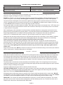
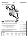
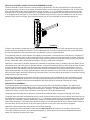
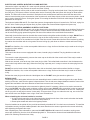
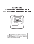
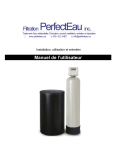
INSTALLATION, OPERATING AND SERVICE MANUAL ELECTRONIC WATER SOFTENER TIME CLOCK MODEL FEATURING THE 2002S VALVE 7-LECT-24 7-LET-24 7-FESLECT-24 • • • •• •• • • • • • • • •• • • • • • • • • • • • • • •• • • • • • • • •• • • • • • • • • 7-FESLET-24 7-LET-32 7-FESLET-32 7-LET-45 7-FESLET-45 7-LET-60 7-FESLET-60 Congratulations on purchasing your new Lancaster Water Filter. This unit is designed to give you many years of trouble free service. For servicing and future inspection purposes, please file this booklet with your important documents. In the event that you need assistance for servicing your water filter, please first contact the professional contractor who installed the system. PAGE 1 OPERATING PARAMETERS Minimum / Maximum Operating Pressures 20 psi (138 kPa) - 125 psi (862 kPa) Minimum / Maximum Operating Temperatures 40°F (4°C) - 110°F (38°C) Current Draw & Voltage 0.5 Amperes - 110 Volts Other Options Available GENERAL WARNINGS The control valve, fittings and/or bypass are designed to accommodate minor plumbing misalignments but are not designed to support the weight of a system or the plumbing. DO NOT use Vaseline, oils, other hydrocarbon lubrications or spray silicone anywhere. A silicone lubricant may be used on black o-rings but is not necessary. Avoid any type of lubricants, including silicone, on red or clear lip seals. The nuts and caps are designed to be unscrewed or tightened by hand or with the optional maintenance wrench (p/n V3193). If necessary, pliers can be used to unscrew the nut or cap. DO NOT use a pipe wrench to tighten or loosen nuts or caps. DO NOT place screwdriver in slots on caps and/or tap with a hammer. Do not use pipe dope or any other sealant on threads. Teflon tape must be used on the threads of the 1” NPT elbow or the 1/4” NPT connection and on the threads for the drain line connection. Teflon tape is not necessary on the nut connection or caps because of o-ring seals. After completing any valve maintenance involving the drive assembly and pistons, unplug power source jack from the printed circuit (PC) board (black wire) and plug back in. This resets the electronics and establishes the service position. All plumbing should be done in accordance with local plumbing codes. The pipe size of the drain line should be a minimum of 1/2”. Backwash flow rates in excess of 7 gpm or length in excess of 20’ require 3/4” drain line. Solder joints near the drain must be done prior to connecting the drain line flow control fitting. Leave at least 6” between the drain line control and fitting solder joints when soldering pipes that are connected on the drain line control fitting. Failure to do this could cause interior damage to the drain line flow control fitting. When assembling the installation fitting package p/n V3007 (inlet and outlet - see page 9), connect the fitting to the plumbing system first and then attach the nut, split ring and o-ring. Heat from soldering or solvent cements may damage the nut, split ring or o-ring. Solder joints should be cool and solvent cements should be set before installing the nut, split ring and o-ring. Avoid getting primer and solvent cement on any part of the o-rings, split rings, bypass valve or control valve. Plug into an electrical outlet. NOTE: All electrical connections must be connected according to local codes. (Be certain the outlet is uninterrupted.) Install grounding strap on metal pipes. INSTALLATION Place softener in desired location close to water supply inlet, after pressure tank, and near a source for waste water, (utility sink, floor drain or sewer line). A 115/120V, 60 Hz uninterrupted outlet is required. Keep softener far enough away from walls and other obstructions to allow enough room for servicing the unit. All sillcocks and similar fixtures that will use untreated water must have their pipes connected to the hard water side of the softener. A bypass valve (optional accessory) should be installed so that water will be available if it should be necessary to shut off the pressure in order to service the softener. The cabinet tank or mineral tank must be reasonably level and solidly in place. Prior to beginning work to the system, make sure that water pressure is shut off at the incoming water supply and that several water spigots are open to provide sufficient venting for drainage of that system. Arrows are molded into the control valve to show the direction of the flow. OPTIONAL BYPASS VALVE: The bypass valve easily connects to the control valve body using nuts that only require hand tightening. Install with red knobs in the upward position. Press end of bypass valve with o-rings into valve. Hand tighten nuts. Place into BYPASS OPERATION (figure 1 page 3). Avoid getting primer and solvent cement on any part of the o-rings or split rings, bypass valve or control valve. DO NOT use pipe dope or any other sealant on threads. Teflon tape is not necessary on the caps because of o-ring seals. DO NOT use Vaseline or other unacceptable lubricants on o-rings. A silicone lubricant may be used on black o-rings. DRAIN LINE: The 3/4” drain line elbow accommodates 5/8” poly tube or 3/4” NPT drain line connections. The nut and poly tube insert for the 3/4” drain line elbow is designed for use with flexible poly tube only. The drain line elbow can be rotated so the outlet can be oriented toward the nearest drain. PAGE 2 H F-XC A N GE H F-XC A N GE O W N y bu to lic k PRESSURE TANK BYPASS SHOULD BE PIPED IN IF OPTIONAL BYPASS VALVE IS NOT USED .d o m w .c o c u-tr a c k C m .c o .d o w w w w w C lic k to bu y N O W ! PD ! PD c u-tr a c k VALVES FROM WELL PUMP SERVICE OUT IN TO 115V RECEPTACLE BRINE LINE TOP VIEW DRAIN LINE FIGURE 1 TO INSTALL 5/8” POLY TUBE DRAIN LINE: The poly tube insert is shipped attached to the drain line elbow’s locking clip. Press the insert into the drain line (5/8” poly tube not included). Loosen nut of the drain line elbow. Press 5/8” poly tube with insert into the drain line elbow until it seats on the back of the fitting. Tighten nut. m .d o w C PD k lic to bu y N O c u-tr a c k W ! .c o H F-XC A N GE It is simplest to run the drain line into a sump pump pit or washing machine drain if possible. If this is not practical, a fitting with a trap must be installed in a sewer line. Place the trap as close to the vent as possible to prevent siphoning of the trap when large amounts of waste water go through the sewer line. DO NOT pipe the drain line solidly into the waste line, as this is prohibited by most plumbing codes. The drain line should enter the trap from above so the water will not back up in the drain line if sewer should become plugged up and the trap overflow. The trap should have a short pipe extending from it to prevent splashing when water runs into the trap from drain line. w w BRINE LINE CONNECTIONS: 3/8” poly tube is shipped inside of the brine tank. The poly tube insert to be used on the control valve fitting is shipped on the brine line elbow’s locking clip. Remove the locking clip by pulling straight out. Remove the white poly tube insert from the locking clip, and replace the locking clip on the brine line elbow of the control valve. Press the poly tube insert into the provided 3/8” poly tube. Press the poly tube and insert into the nut until it is fully seated into the fitting. DO NOT use pipe dope or any other sealant on threads. Teflon tape is not needed on the threads. Tighten nut securely to create a pressure tight connection. Pliers or crescent wrench may be used. The nut, gripper and retainer sleeve is a three piece assembly that can come apart if removed from the elbow body. Parts must be reassembled exactly as shown to function properly. If the nut is completely removed from the body, slip the nut, plastic gripper and retainer sleeve on to the tube then tighten on to the fitting. m to bu y N O c u-tr a c k W ! .c o H F-XC A N GE The poly tube insert used for the brine tank fitting is affixed to the cap of the brine tube next to the brine line fitting during shipping. Install poly tube insert into the end of the 3/8” poly tube and repeat instructions above to install into the brine tank’s brine line fitting. w .d o li ck C PD BRINE TANK OVERFLOW PRECAUTION: Attach a 1/2” poly tube (not provided) to the barbed fitting on the outside of the tank. w w This poly tube should be piped to drain to allow brine to discharge to drain in the event of an overflow condition. PROGRAMMING THE CONTROL VALVE: Note: A quick-reference card is stored inside the front cover of the control valve. To access this card, slightly pull tabs on side of cover outward and pull cover forward. Plug the electrical cord into a 115 Volt receptacle. DO NOT plug into an outlet controlled by a wall switch or pull chain that could inadvertently be turned off. Wait a couple of seconds for control to “home” itself. The time of day will be flashing, an arrow will be pointing to “Time-Hour”. WS1TCvalve & WS1.25 TC Manual Page 11 STEP 1U Set Time of Day SET TIME OF DAY STEP 1: Press and Hold SET for 3 seconds. POWER LOSS: Only the current time of day will need to be reset if power is lost for greater than 8 hours. If power is lost while the system STEP 2: Current time: Adjust hour with ▲ or is regenerating, the control will complete ▼. With 60 Hz line frequency detection on regeneration at the point of interruption once STEP 2U – Current time: Adjustishour with or . PM With 60 Hz linepower frequency on power-up, timekeeping 12 with hour is detection restored. power-up, timekeeping is 12 hour with PM indicator. With 50 Hz line frequency detection on indicator. Press SET to go to Step 3. power-up, timekeeping is 24 hour without the PM indicator. Press SET to go to MESSAGE: Step 3U. ERROR if “E1“, “E2”, “E3” or “E4” appears on the display contact the OEM STEP 3: Adjust minutes with ▲ or ▼. Press for help. This indicates that the valve did not SET to exit Set Time of Day. function properly. STEP 1U – Press SET STEP 2U STEP 3U STEP 3U – Adjust minutes with or . Press SET to exit Set Time of Day. PAGE 3 Page 8 STEP 1ID WS1TC & WS1.25 TC Manual SET REGENERATION TIME AND DAYS BETWEEN REGENERATIONS Installer Displays & Settings (1-99 Days Between Regeneration Option) STEP 1: From normal mode, press SET + ▲ buttons simultaneously for 3 seconds and STEP 1ID – From normal mode, press SET + buttons simultaneously for 3 seconds and release. release. STEP 2ID STEP 3ID STEP Regeneration Hour: Setforthe time fortoregeneration to Press start STEP 2ID2:– Regeneration Time Time Hour: Set the time regeneration start using or . SET to togothetonext thestep. next step. SET to go using ▲ or ▼. Press STEP 3: Regeneration Time Minutes: Set the time for regeneration start using ▲ or ▼. Press STEP – Regeneration Time Minutes: Set the time for regeneration to start using or . SET3ID to go to the next step. Press SET to go to the next step. STEP 4ID STEP 4: Days to Regen: Set the number of days between regenerations. The allowable range is 1 to 99. Press SET to exit. STEP 4ID – Days to Regen: Set the number of days between regenerations. The allowable range is 1 to 99. Press SET to exit Installer Displays and Settings. USE CHART ON OPPOSITE PAGE TO DETERMINE REGENERATION INTERVAL. Return to Normal Mode Displays Settings are (7 Day PLACING UNIT INTO SERVICE: Make sure Installer inlet and outlet&valves to Option) their closed positions. If using optional STEP 1I7 bypass, place in bypass position. Turn on main water supply. Open a cold water faucet. This will clear the lines of any STEP 1I7 – From normal mode, press SET + simultaneously for 3 seconds and release. debris (solder, pipe dope, etc.) that may be in the line. Let water run at tap for a couple of minutes, or until clear. Turn off faucet. Manually add 1½ gallons of water to the brine tank. • Press and hold the ▲ and▼ buttons simultaneously for approximately 5 seconds until the motor starts. STEP 2I7 • Display will read cycle number (ie:C1) and time remaining in cycle. 2I7 – Regeneration Time Hour: Set the time for regeneration to start using or . Press • Wait until displaySTEP reads C1. This is the first BACKWASH position. SET to go to Step 3I7. • Momentarily press ▲ button. Display will read C2. This is the BRINE & RINSE position. • Momentarily press ▲ button again. Valve is now in the second BACKWASH position, C3. If using optional bypass SLOWLY turn bypass valve to DIAGNOSTIC position (figure 2) or slowly open inlet valve to allow water STEPto 3I7slowly enter the softener. STEP 3I7to – Regeneration Timethe Minutes: Set the time for regeneration to start using ▲ or . When water is flowing steadily drain without presence of air, momentarily press button again. Display will read SET to go to Step 4I7. C4. This is the final rinsePress position. Open the outlet valve of the softener, or if using optional bypass place to NORMAL OPERATION MODE (figure 3). Allow control to finish the FINAL RINSE cycle (C4). The control will then advance to the first C5 position. This is an upflow purge that lasts for two minutes. The control will advance to the second C5 position, brine fill. It will then 4I7 FILL position (C5). The brine tank will now automatically fill withDisplay Day of Week advanceSTEP to the the proper volume of water for the first day 1 d1 Sunday regeneration. STEP 4I7 – Current Day of Week: Set the current day of the week by using or (See chart at right for date codes). Press SET to go day 2 d2 Allow the control to automatically advance to the SOFTENING position. C0 will appear forMonday a few seconds, the unit will to STEP 5I7. day 3 d3 Tuesday then display the time of day. day 4 d4 Wednesday Load the brine tank with salt. Solar Salt is recommended. day 5 d5 Thursday SANITIZING: Use 2 oz. of 5¼% household chlorine bleach for each cubic foot of bleach directly into the brine dayresin. 6 d6 PourFriday well of the softener. Press and hold the ▲ and ▼ buttons for 5 – 6 seconds untildaythe motor starts 7 d7 Saturday running. Allow system to complete the regeneration automatically. Check for other local and state codes which may also specify sanitation methods. FIGURE 2 PAGE 4 FIGURE 3 OPTIONAL MAINTENANCE WRENCH V3193 Although no tools are necessary to assemble the valve, the optional maintenance wrench (shown in various positions on the valve) may be purchased to aid in assembly or disassembly. Loosens Drain Nut In Polytube Applications Loosens Injector And Bypass Caps Loosens Quick Connect Nuts Loosens Drive Cap INSTRUCTIONS FOR SELECTING REGENERATION INTERVAL GRAINS OF HARDNESS TO BE REMOVED DAILY To choose the proper regeneration interval, first check the specification table to determine the total grains of hardness per day to be removed. The industry figures 50 gallons of water per person per day to be removed. An automatic washer is figured as a person. Frequent regeneration is beneficial, particularly when larger amounts of iron are involved. GRAINS HARDNESS Example: Family of 4 at 50 gallons each with 13 grains of hardness. 6 NUMBER OF PERSONS IN FAMILY 2 3 4 5 6 600 900 1200 1500 1800 8 800 1200 1600 2000 2400 10 1000 1500 2000 2500 3000 12 1200 1800 2400 3000 3600 14 1400 2100 2800 3500 4200 200 x 13 = 2600 grains per day to be removed. 2600 x 6 = 15600 grains to be removed by 6 day cycle. 16 1600 2400 3200 4000 4800 2600 x 12 = 31200 grains to be removed by 12 day cycle. 18 1800 2700 3600 4500 5400 20 2000 3000 4000 5000 6000 22 2200 3300 4400 5500 6600 25 2500 3750 5000 6250 7500 30 3000 4500 6000 7750 9000 To obtain maximum efficiency per pound of salt, the softener should be set to regenerate at an interval that will utilize the full capacity of the mineral. If 5 parts per million or more of iron are present, it is recommended that the softener be regenerated at least once every 4 days. ELECTRONIC TIME CLOCK SOFTENER STANDARD MODEL NO. 7-LECT-24 7-LET-24 7-LET-32 7-LET-45 7-LET-60 IRONSOFT MODEL NO. 7-FESLECT-24 7-FESLET-24 7-FESLET-32 7-FESLET-45 7-FESLET-60 CAPACITY 24,000 24,000 32,000 TANK SIZE 10” x 35” 8” x 44” 10” x 40” PAGE 5 45,000 10 X 54” 60,000 12” x 48” ADDITIONAL PROGRAMMING INFORMATION AVAILABLE FROM LANCASTER WATER TREATMENT UPON REQUEST. INCLUDES: 7-DAY OPTION, REGENERATION CYCLES, TIMES AND 50 Hz. SERVICE INSTRUCTIONS DRIVE ASSEMBLY: Remove the valve cover to access the drive assembly. Disconnect the power source plug (black wire) from the PC board prior to disconnecting the motor plug from the PC board. The motor plug connects to the two-pin jack on the left-hand side of the PC board. The power source plug connects to the four-pin jack. The PC board can be removed separately from the drive bracket but it is not recommended. Do not attempt to remove the display panel from the PC board. Handle the board by the edges. To remove the PC board from the drive bracket, unplug the power and motor plugs from the PC board. Lift the middle latch along the top of the drive bracket while pulling outward on the top of the PC board. The drive bracket has one plastic pin that fits into the hole in the lower edge of the PC board. Once the PC board is tilted about 45° from the drive bracket it can be lifted off the pin. To reinstall the PC board, position the lower edge of the PC board so that the hole in the PC board lines up with the plastic pin. Push the top of the PC board towards the valve. Align the upper hole on the left hand side of the PC board with the pin and push in until the PC board snaps under the middle latch, weave the power wire into the holders and reconnect the motor and power plugs. The drive bracket must be removed to access the drive cap assembly and pistons or the drive gear cover. It is not necessary to remove the PC board from the drive bracket to remove the drive bracket. To remove the drive bracket start by removing the plug for the power source. Unweave the wire from the side holders. Two tabs on the top of the drive back plate hold the drive bracket in place. Simultaneously lift the two tabs and gently ease the top of the drive bracket toward your body. The lower edge of the drive bracket has two notches that rest on the drive back plate. Lift up and outward on the drive bracket to disengage the notches. To reassemble seat the bottom of the drive bracket so the notches are engaged at the bottom of the drive back plate. Push the top of the drive bracket towards the two latches. The drive bracket may have to be lifted slightly to let the threaded piston rod pass through the hole in the drive bracket. Maintain a slight engaging force on the top of the drive bracket while deflecting the bracket slightly to the left by pressing on the side of the upper right corner. This helps the drive gears mesh with the drive cap assembly. The drive bracket is properly seated when it snaps under the latches on the drive back plate. If resistance is felt before latching, then the notches are not fully engaged, the piston rod is not in the hole, the power wire is jammed between the drive bracket and the drive plate, or the gear is not engaging the drive cap assembly. To inspect drive gears, the drive gear cover needs to be removed. The drive gear is held in place on the drive bracket by three clips. The largest of the three clips is always oriented to the bottom of the drive bracket. Before trying to remove the drive gear cover, the drive bracket must be removed from the drive back plate. The drive gear cover can be removed from the drive bracket without removing the PC board. Simultaneously, push in and down on the large clip at the bottom and the clip on the left-hand side of the drive bracket behind the PC board. Keep your other fingers behind the drive gear cover so the drive gears do not drop on the ground. Replace broken or damaged drive gears. Do not lubricate any of the gears. Avoid getting any foreign matter on the reflective coating because dirt or oils may interfere with pulse counting. The drive gear cover only fits on one way, with the large clip oriented towards the bottom. If all three clips are outside of the gear shroud on the drive bracket the drive gear cover slips easily into place. The drive bracket does not need to be removed from the drive plate if the motor needs to be removed. To remove the motor, disconnect the power and motor plugs from the jacks on the PC board. Move the spring clip loop to the right and hold. Rotate the motor at least a ¼ turn in either direction before gently pulling on the wire connectors to remove the motor. Pulling directly on the wire without rotating the motor may break the wires off the motor. Replace the motor if necessary. Do not lubricate the motor or the gears. When reinstalling the motor gently turn the motor while inserting so that the gear on the motor meshes with the gears under the drive gear cover and the small plastic plug engages one of the slots on the motor housing. Reconnect the motor plug to the two pronged jack on the lower left-hand side of the PC board. If the motor will not easily engage with the drive gear when reinstalling, lift and slightly rotate motor before reinserting. Replace the valve cover. After completing any valve maintenance, press and hold SET HOUR and ▼ buttons for 5 seconds or unplug power source jack (black wire) from the circuit board and plug back in. This resets the electronics and establishes the home position for softening. Reset the time of day. PAGE 6 DRIVE CAP ASSEMBLY, MAIN PISTON AND REGENERANT PISTON: The drive assembly must be removed to access the drive cap assembly. The drive cap assembly must be removed to access the piston(s). The drive cap assembly is threaded into the control valve body and seals the o-ring. To remove the drive cap assembly use the optional maintenance wrench or insert a ¼” to ½” flat bladed screwdriver into one the slots around the top 2” of the drive cap assembly so it engages the notches molded into the drive back plate around the top 2” of the piston cavity (see figure 4). The notches are visible through the holes. Lever the screwdriver so the drive cap assembly turns counter clockwise. Once loosened unscrew the drive cap assembly by hand and pull straight out. FIGURE 4 The drive cap assembly contains the drive cap, the main drive gear, drive cap spline, piston rod and various other parts that should not be dissembled in the field. The only replaceable part on the drive cap assembly is the o-ring. Attached to the drive cap assembly is the main piston and, if a regenerant is used, a regenerant piston. The regenerant piston (the small diameter one behind the main piston) is removed from the main piston by unsnapping it from its latch. Chemically clean in dilute sodium bisulfite or vinegar or replace the regenerant piston if needed. To remove the main piston fully extend the piston rod and then unsnap the main piston from its latch by pressing on the side with the number. Chemically clean in diluted sodium bisulfite or vinegar or replace the main piston. Reattach the main piston to the drive cap assembly. Reattach the regenerant piston (if needed) to the main piston. Do not lubricate the piston rod, main piston or regenerant piston. Lubricant will adversely affect the red or clear lip seals. Reinsert the drive cap assembly and piston into the spacer stack assembly and hand tighten the drive cap assembly. Continue to tighten the drive cap assembly using the maintenance wrench or screwdriver as a ratchet until the black o-ring on the spacer stack assembly is no longer visible through the drain port. Excessive force can break the notches molded into the drive back plate. Make certain the main drive gear still turns freely. The exact position of the piston is not important as long as the main drive gear turns freely. Reattach the drive assembly to the control valve and connect all plugs. After completing any valve maintenance, press and hold SET HOUR and ▼ buttons for 5 seconds or unplug power source jack (black wire) from the circuit board and plug back in. This resets the electronics and establishes the home position for softening. Reset the time of day. SPACER STACK ASSEMBLY: To access the spacer stack assembly remove the drive assembly, drive cap assembly and piston. The spacer stack assembly can be removed easily without tools by using your thumb and forefinger. Inspect the black o-rings and red or clear lip seals for wear or damage. Replace the entire stack if necessary. The spacer stack assembly has been 100% tested at the factory to insure proper orientation of one way seals. Do not disassemble stack. The spacer stack assembly may be chemically cleaned (dilute sodium bisulfite or vinegar) or wipe with a soft cloth. The spacer stack assembly can be pushed into the control valve body bore by hand. Since the spacer stack assembly can be compressed it is easier to use a blunt object (⅝” to 1⅛” in diameter) to push the center of the assembly into the control valve body. The assembly is properly seated when at least four threads are exposed (approximately ⅝”) Do not force the spacer stack assembly in. The control valve body bore interior can be lubricated with silicone to allow for easy insertion of the entire stack. Do not use silicone or any other type of lubricant on the red or clear lips seals or the piston. Reattach the drive cap assembly and piston(s) and the drive assembly. After completing any valve maintenance, press and hold SET HOUR and ▼ buttons for 5 seconds or unplug power source jack (black wire) from the circuit board and plug back in. This resets the electronics and establishes the home position for softening. Reset the time of day. PAGE 7 INJECTOR CAP, SCREEN, INJECTOR PLUG AND INJECTOR: Unscrew the injector cap and lift off. Loosen cap with optional maintenance wrench or pliers if necessary. A screen is attached to the injector cap. Remove the screen and clean if fouled. The plug and/or injector can be pried out with a small screwdriver. The plug can be wiped clean. If the plug leaks replace the entire plug. The injector consist of a throat and a nozzle. Chemically clean the injector with vinegar or dilute sodium bisulfite. The holes can be blown out with air. Both pieces have small diameter holes that control the flow rates of the water to insure that the proper concentration of the regenerant is used. Sharp objects, which can score the plastic, should not be used to clean the injector. Scoring the injector or increasing the diameter of the hole could change the operating parameters of the injector. Two holes are labeled DN and UP. For down flow systems, the appropriate injector is located in the “DN” hole, a plug is in the “UP” hole. Push the plug and injector firmly in place, replace the screen and hand tighten the injector cap. REFILL FLOW CONTROL ASSEMBLY OR REFILL PORT PLUG: To clean or replace the refill flow control, pull out the elbow-locking clip and then pull straight up on the elbow. Replace the elbow locking clip in the slot so that it is not misplaced. Twist to remove the white flow control retainer. The flow control can be removed by prying upward through the side slots of the retainer with a small blade flat screwdriver. Chemically clean the flow control or the white flow control retainer using dilute sodium bisulfite or vinegar. DO NOT use a wire brush. If necessary, replace the flow control, o-ring on the flow control retainer, or the o-ring on the elbow. Reseat the flow control so the rounded end is visible in the flow control. Reseat the white flow control retainer by pushing the retainer into the elbow until the o-ring seats. Remove locking clip, push down on elbow to reseat and insert locking clip. DO NOT use Vaseline, oils, or other unacceptable lubricants on o-rings. A silicone lubricant may be used on the o-ring on the elbow or white retainer. METER PLUG: This control valve does not come equipped with a meter, instead a plug is installed. The plug should not need to be serviced. To remove the meter plug assembly, unscrew the meter cap on the left side of the control valve. Pliers may be used to unscrew the nut if necessary. With the nut removed, a slot at the top of the meter plug is visible. Twist a flat blade screwdriver in the slot between the control valve body and the meter plug. When the meter plug is part way out it is easy to remove the meter plug from the housing. DO NOT use a wire brush to clean. Wipe with a clean cloth or chemically clean in dilute sodium bisulfite or vinegar. DO NOT use Vaseline, oils, or other unacceptable lubricants on o-rings. A silicone lubricant may be used on the black o-ring. Reinsert the meter plug into the side slot. Hand tighten the nut. DO NOT use a pipe wrench to tighten nut. BYPASS VALVE: The working parts of the bypass valve are the rotor assemblies that are contained under the bypass valve caps. Before working on the rotor, make sure the system is depressurized. Turn the red arrow shaped handles toward the center of the bypass valve and back to the arrow direction several times to ensure rotor is turning freely. The nuts and caps are designed to be unscrewed or tighten by hand. If necessary a pliers can be used to unscrew the nut or cap. DO NOT use a pipe wrench to tighten or loosen nuts or caps. DO NOT place screwdriver in slots on caps and/ or tap with a hammer. To access the rotor, unscrew the cap and lift the cap, rotor and handle out as one unit. Twisting the unit as you pull it out will help to remove it more easily. There are three o-rings: one under the rotor cap, one on the rotor stem and the rotor seal. Replace worn o-rings. Clean rotor. Reinstall rotor. When reinstalling the red arrow handles be sure that: 1. O-rings on both rotors face to the right when being viewed from the front of the control valve when the handle pointers are lined up with the control valve body arrows; or 2. Arrows point toward each other in the bypass position. Since the handles can be pulled off, they could be accidentally reinstalled 180° from their correct orientation. To install the red handles correctly, keep the handles pointed in the same direction as the arrows engraved on the control valve body while tightening the bypass valve caps. After completing any valve maintenance, press and hold SET HOUR and ▼ buttons for 5 seconds or unplug power source jack (black wire) from the circuit board and plug back in. This resets the electronics and establishes the home position for softening. Reset the time of day. PAGE 8 PARTS V3007-02 1” Brass Sweat Assembly Optional Item No. Quantity Part No. Description 1 2 V3151 Nut 1” Quick Connect 2 2 V3150 Split Ring 3 2 V3105 O-Ring 215 4 2 V3188 Fitting - 1” Brass Sweat V3007-03 3/4” Brass Sweat Assembly Optional Item No. Quantity Part No. Description 1 2 V3151 Nut 1” Quick Connect 2 2 V3150 Split Ring 3 2 V3105 O-Ring 215 4 2 V3188 Fitting - 3/4” Brass Sweat V3007 1” PVC Male NPT Elbow Assembly Standard Description 1 2 V3151 Nut 1” Quick Connect 2 2 V3150 Split Ring 3 2 V3105 O-Ring 215 4 2 V3145 Bypass 1” Rotor 5 2 V3146 Bypass Cap 6 2 V3147 Bypass Handle 7 2 V3148 Bypass Rotor Seal Retainer 8 2 V3152 O-Ring 135 9 2 V3155 O-Ring 112 10 2 V3156 O-Ring 214 Item No. Quantity 1 2 H F-XC A N GE Part No. Description 2 V3151 Nut 1” Quick Connect 2 V3150 Split Ring 2 V3105 O-Ring 215 2 V3149 1” PVC Male NPT Elbow c u-tr a c k .c 1 2 3 Description 1 2 V3151 Nut 1” Quick Connect 2 2 V3150 Split Ring 3 2 V3105 O-Ring 215 4 2 V3191 Vertical Adapter 4 4740 Brine Valve Assembly ADDITIONAL OPTIONAL FITTINGS Part Number Description V3007-01 3/4” X 1” PVC Solvent Elbow Assembly 1 1 V3007-11 1” PEX Brass Assembly 2 2 10151 Pin V3007-12 3/4” Shark Bite Assembly 3 1 H4640-32 Float Assembly V3007-13 1” Shark Bite Assembly 4 1 H4500-30.50 Air Check Assembly Item No. Quantity PAGE 9 Part No. Description H4600 3/8” Safety Brine Valve C W O N y bu to k lic C .d o w w w w 4 w 3 Part No. PD ! PD w V3191-01 Vertical Adapter Assembly Optional Item No. Quantity m o BP2000 Bypass Valve Item No. Quantity Part No. .d Not Shown V3186EU WS1 AC ADAPTER 220-240V-12V EU V3186UK WS1 AC ADAPTER 220-240V-12V UK V3186-01 WS1 AC ADAPTER CORD ONLY 1 * Drawing number parts 2 through 6 may be purchased as a complete assembly, part V3002. When replacing the battery, align positives and push down to fully seat. Correct Battery Orientation FRONT COVER AND DRIVE ASSEMBLY Battery replacement is 3 volt lithium coin cell type 2032. Item No. Quantity Part No. Description 1 1 V3175TC Front Cover Assembly WS1TC & WS1.25 TC Manual Battery Fully Seated Page WS1TC Drive Cap Assembly, Downow Stack Assembly 2 1 Piston, Regenerant V3107 Piston and Spacer Motor 3 1 1 Description Drawing No. Order No. 1 V3005 WS1 Spacer 4 Stack Assembly 1 2 V3004 Drive Cap 5 ASY 3 V3178 WS1 Drive Back Plate 4 V3011 6 WS1 Piston Downow ASY 4 5 5 6 6 3 1 V3174 2-6 WS1 Regenerant Piston* V3135 O-ring 228 NOT 1 V3180 O-ring 337 SHOWN 8 V3105 O-ring 215 (Distributer Tube) V3001 WS1 Body ASY Downow Not Shown 3 V3001-02 Drive Quantity Bracket/Spring Clip 1 PC Board V3110 1 Drive Gear Cover V32109 1 Drive Assembly V3002TC 1 Drive Assembly (parts 2-6) 1 1 V3186 7 2 V3106 V3108TC Transformer 110V-12V 1 1 1 WS1 Mixing Valve Body ASY Note: The regenerant piston is not used in backwash only applications. 3 DRIVE CAP ASSEMBLY, DOWN FLOW PISTON, REGENERANT PISTON AND SPACER STACK ASSEMBLY Item No. Quantity Part No. Description 1 1 V3005 Spacer Stack Assembly 2 1 V3004 Drive Cap Assembly 3 1 V3135 O-Ring 228 4 1 V3011 Page 5 Piston Assembly 5 1 V3174 Regenerant Piston 1 V3180 25 Drawings & Service Manual Injector Cap, Injector Screen, Injector, Plug and O-Ring Drawing No. 1 2 3 4 5 Not Shown Not Shown 6 Order No. V3176 V3152 V3177-01 V3010-1Z V3010-1A V3010-1B V3010-1C V3010-1D V3010-1E V3010-1F V3010-1G V3010-1H V3010-1I V3010-1J V3010-1K V3170 V3171 Description INJECTOR CAP O-RING 135 INJECTOR SCREEN CAGE WS1 INJECTOR ASY Z PLUG WS1 INJECTOR ASY A BLACK WS1 INJECTOR ASY B BROWN WS1 INJECTOR ASY C VIOLET WS1 INJECTOR ASY D RED WS1 INJECTOR ASY E WHITE WS1 INJECTOR ASY F BLUE WS1 INJECTOR ASY G YELLOW WS1 INJECTOR ASY H GREEN WS1 INJECTOR ASY I ORANGE WS1 INJECTOR ASY J LIGHT BLUE WS1 INJECTOR ASY K LIGHT GREEN O-RING 011 O-RING 013 Quantity 1 1 1 1 1 O-Ring 3374b Black Plu 2 1 5 7 4a 4 * * 8 * The injector plug and the injector each contain one 011 (lower) and 013 (upper) o-ring. 6 Note: For upow position, injector is located in the up hole and injector plug is in the other hole. WS1 upow bodies are identied by having the DN marking removed. Upow option is not applicable to EE, EI, or TC control valves. For a lter that only backwashes, injector plugs are located in both holes. INJECTOR, INJECTOR CAP, SCREEN AND O-RING 1 2 3 4 5 Item No. Quantity Part No. Description 1 1 V3176 Injector Cap 2 1 V3152 O-Ring 135 3 1 V3177 Injector Screen 4 1 V3010-1Z Injector Assy. Z Plug 5 1 V3010-1C Injector Assy. C Violet - 8” Tank 5 1 V3010-1E Injector Assy. E White - 10” Tank 5 1 V3010-1F Injector Assy. F Blue - 12” Tank NOT SHOWN * V3170 O-Ring 011 NOT * V3171 O-Ring 013 SHOWN * Injector plug and injector contains one 011 and one 013 O-ring PAGE 10 WS1 & WS1.25 Drawings & Service Manual 4 Page 6 4 6 – 3/4” Drain Line Drawing No. 1 2 3 4* 5 6* Order No. Description Quantity H4615 Elbow Locking Clip 1 PKP10TS8-BULK Polytube insert 5/8 Option V3192 WS1 Nut ¾ Drain Elbow Option V3158-01 WS1 Drain Elbow ¾ Male 1 V3163 O-ring 019 1 V3159-01 WS1 DLFC Retainer ASY 1 V3162-007 WS1 DLFC 0.7 gpm for ¾ V3162-010 3 WS1 DLFC 1.0 gpm for ¾ V3162-013 WS1 DLFC 1.3 gpm for ¾ V3162-017 WS1 DLFC 1.7 gpm for ¾ One DLFC V3162-022 WS1 DLFC 2.2 gpm for ¾ must be V3162-027 WS1 DLFC 2.7 gpm for ¾ 7 V3162-032 WS1 DLFC 3.2 gpm for ¾ used if ¾ V3162-042 WS1 DLFC 4.2 gpm for ¾ tting is V3162-053 WS1 DLFC 5.3 gpm for ¾ used V3162-065 WS1 DLFC 6.5 gpm for ¾ V3162-075 WS1 DLFC 7.5 gpm for ¾ V3162-090 WS1 DLFC 9.0 gpm for ¾ V3162-100 WS1 DLFC 10.0 gpm for ¾ *4 and 6 can be ordered as a complete assembly - V3331 WS1 Drain Elbow and Retainer Asy METER PLUG 5 2 5 Item No. Quantity Part No. Description 1 1 V3151 Nut 1” QC 1 V3105 O-Ring 215 1 V3003 Meter Plug Assembly 2 3 3 3 2 2 1 Valves are shipped 1 without drain line ow control (DLFC) - install DLFC before using. Valves are shipped without ¾ nut for drain elbow (polytube installation only) and 5/8" polytube insert (polytube installation only). DRAIN LINENOT - 3/4” ATER METER SHOULD BE USED AS THE PRIMARY MONITORING DEVICE FOR CRITICAL HEALTH DEVICE FOR CRITICAL HEALTH THIS WATER METER SHOULD NOT BE USED AS THE PRIMARY MONITORING APPLICATIONS. Item no. Quantity Part No. Description EFFECT APPLICATIONS. 1 for a TC H4615 A water meter is 1not applicable control valve. Elbow Locking Clip 2 1 3 1 NOTE: A water meter is not applicable for a TC control valve. V3194 Polytube Insert 5/8 V3192 Nut for 3/4 Drain Elbow 1 V3158 3/4 Drain Elbow 5 1 V3163 WS1 & WS1.25 Drawings & Service Manual V3159 DLFC Retainer 6 7 1 1 Drawing No. Order No. 1 V3195-01 7 1 4 4 Page 14 O-Ring 019 Refill Flow Control Assembly and Refill Port Plug V3162-017 DLFCThis 1.7 for 8”Quantity Tank part is required for backwash only sys- Description WS1 Refill Port Plug Asy V3162-022 DLFC 2.2 for 10”tems Tank 1 2 H4615 Elbow Locking Clip 3 JCP-P-6 Polytube insert 3/8” 4 JCPG-6PBLK Nut 3/8” 5 H4613 Elbow Cap 3/8” 6 V3163 0-ring 019 7 V3165-01* WS1 RFC Retainer Asy 8 V3182 WS1 RFC 9 V3330-01 WS1 Brine Elbow Asy w/RFC 3/8" Not Shown V3552 WS1 Brine Elbow Asy w/RFC 1/2" Not Shown H4650 Elbow ½” with nut and insert *Assembly includes V3182 WS1 RFC. 7 1 V3162-027 1 DLFC 2.7 for 10” Tank 1 7 1 V3162-032 DLFC 3.2 for 12” Tank 1 1 1 1 1 Option Option Water Flow Proper DLFC orientation directs water ow towards the washer face with rounded edge. 9 BRINE REFILL Item No. Quantity Water Flow Part No. Description 1 1 H4615 Elbow Locking Clip 2 1 H4614 Polytube Insert 3/8” 3 1 H4612 Nut 3/8” 4 1 H4613 Elbow Cap 3/8” 5 1 V3163 O-Ring 019 6 1 V3165 RFC Retainer Assy 7 1 V3182 *Par No. V3165-01 Includes Items 6 and 7 Proper RFC orientation directs rell water ow towards the washer face with rounded edge and text. PAGE 11 RFC PROBLEM TROUBLESHOOTING POSSIBLE CAUSE a. Transformer unplugged 1. Timer does not display time of day. b. No electric power at outlet c. Defective transformer d. Defective PC board 2. Timer does not display correct time of day. a. Switched outlet b. Power outage c. Defective PC board a. Power outages 3. Control valve regenerates at wrong time of day. 4. E1, E2 OR E3: Unable to recognize start of regeneration. Unexpected stall. Motor ran to long, timed out trying to reach next cycle position, or trying to reach home b. Time of day not set correctly c. Time of regeneration incorrect a. Control valve has just been serviced b. Foreign matter is lodged in control valve c. High drive forces on piston d. Control valve piston not in home position e. Motor not inserted fully to engage pinion, motor wires broken or disconnected, motor failure f. Drive gear label dirty or damaged, missing or broken gear g. Drive bracket incorrectly aligned to back plate h. PC board is damaged or defective i. PC board incorrectly aligned to drive bracket a. Motor not operating b. No electric power at outlet c. Defective transformer d. Defective PC board 5. Control valve stalled in regeneration. e. Broken drive gear or drive cap assembly f. Broken piston retainer g. Broken main or regenerant piston a. Transformer unplugged b. No electric power at outlet 6. Control valve does not regenerate automatically when ▲ and ▼ buttons are c. Broken drive gear or drive cap depressed and held. assembly d. Defective PC board a. Defective PC board 7. Control valve does not regenerate automatically but does when ▲ and ▼ b. Set-up error buttons are depressed. 10/12 SOLUTION a. b. c. d. a. Connect power Repair outlet or use working outlet Replace transformer Replace PC board Use uninterrupted outlet b. Reset time of day c. Replace PC board a. Reset control valve to correct time of day b. Reset to correct time of day c. Reset regeneration time a. Press SET HOUR and ▼ for 5 seconds or unplug power source jack (black wire) and plug back in to reset control valve. Reset time of day. b. Check piston and spacer stack assembly for foreign matter. c. Replace piston (s) and spacer stack assembly. d. Press SET HOUR and ▼ for 5 seconds or unplug power source jack (black wire) and plug back in to reset control valve. Reset time of day. e. Check motor and wiring. Replace motor if necessary. f. Replace or clean drive gear. g. Reset drive bracket properly. h. Replace PC board. i. Ensure PC board is correctly snapped onto drive bracket. a. Replace motor b. Repair outlet or use working outlet c. Replace transformer d. Replace PC board e. Replace drive gear or drive cap assembly f. Replace drive cap assembly g. Replace main or regenerant piston a. Connect transformer b. Repair outlet or use working outlet c. Replace drive gear or drive cap assembly d. Replace PC board a. Replace PC board b. Check control valve set-up procedure A DIVISION OF C-B TOOL CO. 1340 MANHEIM PIKE ● LANCASTER PA 17601-3196 ● TEL:717-397-3521 ● FAX: 717-392-0266 www.lancasterwatertreatment.com ● E-mail: [email protected] PAGE 12