1
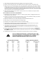
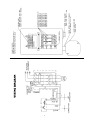
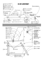
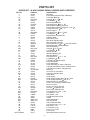
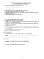
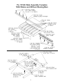
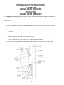
MODEL FBC-4800SS
STAINLESS STEEL
MODEL
FBC-4800SS
FROZEN MEAT
CHIPPER
STAINLESS
STEEL
Operating Manual and Parts List
FROZEN
MEAT
Applicable
on Machines
Starting CHIPPER
with Serial No. 10200
Operating Manual and Parts List
Applicable on Machines Starting with Serial No. 10200
Biro Designed
Biro Built
+
IMPORTANT NOTICE
This Manual contains important
safety instructions which must
be strictly followed when using
this equipment.
+
PTCT
FBC-4800
029-10-05-16
029-5-10-18
TABLE OF CONTENTS
Page
NOTICE
TO OWNERS
OWNERS AND
OPERATORS .....
NOTICE TO
AND OPERATORS
...
...
...
...
...
...
...
...
...
...
...
...
...
...
............................................................................
..11
SAFETY
SAFETYTIPS
TIPS ..
...
...
...
...
...
...
...
...
...
...
...
...
...
...
...
...
...
...
...
...
............................................................................................................................
...
..22
INSTALLATION.
INSTALLATION...
...
...
...
...
...
...
...
...
...
...
...
...
...
...
...
...
...
...
...
.........................................................................................................................
...
..33
UNCRATING
UNCRATING AND
AND SET
SET UP
UP.....
...
...
...
...
...
...
...
...
...
...
...
...
...
...
...
........................................................................................
..3-4
3-4
WIRING
WIRINGDIAGRAM
DIAGRAM..
...
...
...
...
...
...
...
...
...
...
...
...
...
...
...
...
...
...
.......................................................................................................
...
..55
OPERATION
OPERATION..
...
...
...
...
...
...
...
...
...
...
...
...
...
...
...
...
...
...
...
...
...
...............................................................................................................................
..66
TO
PRODUCT .....
TO PROCESS
PROCESS PRODUCT
...
...
...
...
...
...
...
...
...
...
...
...
...
...
...
...........................................................................................
...
..66
TROUBLE
MACHINE OPERATION
OPERATION .....
TROUBLE SHOOTING
SHOOTING MACHINE
...
...
...
...
...
...
...
...
...
...
..............................................................7
MAINTENANCE
MAINTENANCE ..
...
...
...
...
...
...
...
...
...
...
...
...
...
...
...
...
...
...
...
...
.........................................................................................................................
..88
CLEANING
CLEANING ..
...
...
...
...
...
...
...
...
...
...
...
...
...
...
...
...
...
...
...
...
...
...............................................................................................................................
...
..99
PARTS
PARTSDIAGRAMS
DIAGRAMS..
...
...
...
...
...
...
...
...
...
...
...
...
...
...
...
...
...
...
...
................................................................................................................
...
..10
. 10
RUNNER
RUNNERAND
ANDGUILLOTINE
GUILLOTINE BLADE
BLADE REPLACEMENT
REPLACEMENT........
...
...
...
...
...
...
...
...
.......................................................
..14-15
. 14-15
LUBRICATION
LUBRICATION ..
...
...
...
...
...
...
...
...
...
...
...
...
...
...
...
...
...
...
...
...
.........................................................................................................................
..14
. 14
GGROVE
R OVE GEAR
GEAR REDUCER
REDUCERDIAGRAM
DIAGRAM&& LUBRICATION
LUBRICATION.........
...
...
...
...
...
.....................................
..16-17-18-19-20
. 16-17-18-19-20
MORSE
LUBRICATION .........
MORSEGEAR
GEARREDUCER
REDUCERDIAGRAM
DIAGRAM&& LUBRICATION
...
...
...
...
...
...
...
...
...
.......................................................
..21
. 21
OLD
AND
STYLE
AND
NOTES
OPERATOR'S
NOTES.
. . . . . . . AND
. . . . .OPERAT
. . . . . . O. R’S
. . . .NOTES
. . . . . .........
...
...
...
...
...
...
...
..............................................
..22
. 22
OLD
AND NEW
NEW
STYLE.BLADES
BLADES
OPERATOR’S
OPTIONAL
MEAT
FILLER PLATE
....
OPERATOR’S
SIGNATURE
PAGE.
...
...
...
...
...
...
...
...
...
...
...
...
...
...
...
...........................................................................................
..23
. 23
NOTES
...WARRANTY
.....................
LIMITED
...
...
...
...
...
...
...
...
...
...
.....................................................................................................................................
...
..24
. 24
OPERAT O R’S SIGNATURE PAG E ................................................................................................25
LIMITED WARRANTY ..................................................................................................................26
NOTICE TO OWNERS AND OPERATORS
BIRO’s products are designed to process food products safely and efficiently. Unless the operator is properly trained and supervised, however, there is the possibility of a serious injury. It is the
responsibility of the owner to assure that this machine is used properly and safely, strictly following
the instructions contained in this Manual and any requirements of local law.
No one should use or service this machine without proper training and supervision. All operators should be thoroughly familiar with the procedures contained in this Manual. Even so BIRO
cannot anticipate every circumstance or environment in which its products will be used. You, the
owner and operator, must remain alert to the hazards posed by the function of this equipment —
particularly the MOVING SHUTTLE WITH SHARP CHIPPING BLADES, which can severly injure an
inattentive operator amputating fingers and limbs. No one under eighteen (18) years of age
should operate this equipment. If you are uncertain about a particular task, ask your supervisor.
This Manual contains a number of safe practices in the SAFETY TIPS section. Additional warnings are placed throughout the Manual. Warnings related to your personal safety are indicated by:
OR
Warnings related to possible damage are indicated by:
BIRO also has provided warning labels on the equipment. If any warning label or Manual becomes misplaced, damaged, or illegible, please contact your nearest Distributor or BIRO directly
for a replacement.
Remember, however, this Manual or the warning labels do not replace the need to be alert and
to use your common sense when using this equipment.
This Manual applies to SANITARY TIN machines with serial numbers 3100 to 5297, and
STAINLESS STEEL machines with serial numbers 10200 to present.
- NOTE A copyTHE
of thisBIRO
manualMANUFACTURING
is included with each MODEL
FBC-4800SS
COMPANY
FROZEN MEAT
CHOPPER
MACHINE.
1114
Main Street
MARBLEHEAD, OHIO 43440-2099 U.S.A.
The descriptions and illustrations contained in this manual are not
Phone (419) 798-4451
binding. The manufacturer reserves the right to introduce any
Fax (419) 798-9106
modification without updating the manual.
E-mail: [email protected]
Web: http://www.birosaw.com
1
SAFETY TIPS
MOVING SHUTTLE WITH SHARP CHIPPING BLADES
TO AVOID SERIOUS PERSONAL INJURY
· NEVER Touch This Machine without Training and Authorization by Your Supervisor.
· ALWAYS Keep Hands Clear of Sharp Chipping Blades and Other Moving Parts.
· ONLY Use a Qualified Electrician to Install According to Local Building Codes: Machine MUST
Be Properly Grounded.
· ONLY Install on Level, Non-Skid Surface in a Clean, Well-Lighted Work Area Away from
Children and Visitors.
· DO NOT Tamper With or Remove Product Chute Cover.
· NEVER Operate With the Product Chute Cover in the Open Position.
· ALWAYS Close Product Chute Cover Completely Before Operating Machine.
· ALWAYS Turn Off, Unplug From Power Source and Perform Lockout/Tagout Procedure to
This Machine BEFORE Cleaning or Servicing.
· NEVER Leave Machine Unattended While Operating.
· PROMPTLY REPLACE Any Worn or Illegible Warning Labels.
· ALWAYS Read Operation and Service Manual BEFORE Operating, Cleaning, or Servicing.
· USE ONLY BIRO Parts and Accessories Properly Installed.
2
INSTALLATION
TO AVOID SERIOUS PERSONAL INJURY, PROPERLY INSTALL
EQUIPMENT IN ADEQUATE WORK AREA
· ALWAYS Use Qualified Technician and Electrician for Installation.
· ALWAYS Connect to Proper Voltage & Phase.
· ALWAYS Install Equipment in Work Area with Adequate Light and Space Away From Children
and Visitors.
· ONLY Operate on a Solid, Level, Non-Skid Surface.
· NEVER Bypass, Alter, or Modify This Equipment in Any Way From Its Original Condition.
· NEVER Operate With Product Chute Cover in Open Position.
· NEVER Operate Without all Warning Labels Attached and Owner/Operator Manual Available to
the Operator.
UNCRATING AND SET UP
1. Read this Manual thoroughly before installation and operation. Do not proceed with installation and operation if
you have any questions or do not understand anything in this Manual. Contact your local Distributor, or BIRO
FIRST.
2. Carefully remove cardboard crate wraparound. Remove meat lug dolly and set aside.
3. Remove 3 8 bolt and nut holding machine to wood crate bottom.
4. Remove Meat Lug (Item No. 51199-MHD) from top of machine.
5. Install casters (3 ea. Item No. 51165 less brake and 1 ea. Item No. 51164 with brake) on the stainless steel Meat
Lug Dolly (Item No. 51582) with supplied fasteners. Set Meat Lug and Dolly aside.
6. With assistance of mechanical devices lift machine and block up. Remove machine legs from side of machine.
Replace legs to same mounting holes in vertical position, tightening the acorn nuts on the carriage bolts.
7. Remove stainless steel Chute Cover (Item No. 51597) from top of machine. Turn over and mount to stand offs at
top of chute opening. Tighten Chute Cover Hinge Pins (Item No. 51563). Do not over tighten. Chute should be
centered and still have free movement to open and close. Magnet should be centered over safety switch.
Tighten jam nuts on hinge pins.
8. Install Chute Cover Support (Item No. 51404) to Chute Cover. Be sure bushing is used to allow free movement
of chute support. Be sure chute support is in lock bracket welded to side of chute.
9. Place machine on a level, solid, non-skid surface in a well-lighted work area away from children and visitors.
10. Install floor stops over the front leg pads (opposite motor end). It is recommended that floor stops be anchored
to the floor with two 3 8-16 ´ 11 2" expansion anchors per floor stop.
3
11. After checking and making sure that the power supply is correct, plug in your machine.
12. Machine must be properly grounded. Use qualified electrician to install according to local building codes.
13. With rear motor cover removed and chute cover in the closed position, push the green “start” button located on
the side of the rear cover. Be sure that the motor and transmission are rotating in the proper direction. Should
be COUNTERCLOCKWISE when viewing the transmission output shaft and machine crank arm, as indicated by
the arrow on crank arm. Should machine be operating backwards, push red “stop” button. Disconnect machine
from incoming power source and interchange two lead wires.
14. When machine is operating in proper direction, replace rear motor cover. Machine is now ready for trained
operators to process product.
MOTOR WIRING AND ELECTRICAL REQUIREMENTS
(1) Interchange of current is made in motor outlet box. Leads are properly marked. Changing instructions are on
the motor plate or motor outlet box.
(2) All chippers are wired 220 volts unless otherwise specified. Be sure motor specifications (voltage, cycle, phase)
match power supply line. Be sure line voltage is up to specification.
(3) Electrical connections to be in accordance with safety codes and National Electrical Code.
(4) Rated voltage of the unit shall be identical with full supply voltage.
(5) Voltage drop on the supply line shall not exceed 10% of full supply voltage.
(6) The feederline conductor size in the raceway from the branch circuit to the unit must be correct to assure
adequate voltage under heavy starting and short overload conditions.
(7) The feederline conductor shall only be used for the supply of one unit of the relevant horsepower. For
connections of more than one unit on the same feederline, a local electrician will have to be consulted to
determine the proper conductor size.
(8) The size of the electrical wiring required from the power source to the frozen block chipper is a MINIMUM OF
No. 10 WIRE if the distance from the machine to electrical box is 25 feet or less. Over 25 feet a MINIMUM OF
No. 8 WIRE is to be used.
(9) The BIRO Manufacturing Company is not responsible for permanent wiring, connection or installation.
NOTE TO OWNER AND ELECTRICIAN: IF THIS MACHINE IS NOT CORD
AND PLUG CONNECTED TO THE ELECTRICAL SUPPLY SOURCE, THEN IT
SHOULD BE EQUIPPED WITH, OR CONNECTED TO, A LOCKABLE,
MANUALLY-OPERATED DISCONNECT SWITCH (OSHA 1010.147).
MOTOR SPECIFICATIONS
VOLTS
208
230
460
575
190
220
380
415
HERTZ
60
60
60
60
50
50
50
50
FURNAS HEATER ELEMENTS
AMPS
16.2
14.0
7.0
6.0
16.7
14.4
8.7
8.0
CODE NO.
E62
E61
E51
E50
E62
E60
E54
E53
4
BIRO ITEM NO.
50704
52744
50703
50668
50704
50667
50705
50670
5
OPERATION
MOVING SHUTTLE WITH SHARP CHIPPING BLADES
TO AVOID SERIOUS PERSONAL INJURY
· ONLY Properly Trained Personnel Should Use This Equipment.
· ALWAYS Keep Hands Clear of Sharp Chipping Blades and Other Moving Parts.
· NEVER Operate With Product Chute Cover in the Open Position.
· DO NOT Tamper With or Remove Product Chute Cover.
· ALWAYS Close Product Chute Cover Completely Before Operating Machine.
· DO NOT Tamper With, Bypass, Alter, or Modify This Equipment in Any Way From Its Original
Condition.
· ALWAYS Turn Off, Unplug from Power Source and Perform Lockout/Tagout Procedure to This
Machine Before Cleaning or Servicing, or When Not in Use.
· NEVER Leave Unattended While Operating.
· NEVER Operate Without All Warnings Attached.
A. TO PROCESS PRODUCT
1. Place Meat Lug under machine to catch chipped product.
2. Prepare for processing a 60 pound tempered meat block. For optimum chipping the recommended block
temperature is 15 to 25 degrees F. With a maximum block size of 8" ´ 161 2" ´ 191 2". This will yield finished
product chips approx. 31 2" ´ 31 2" ´ 1 4". For narrower meat blocks there is available an optional Chute Filler
Plate (Item No. 51526).
3. Lift the Chute Cover slightly to release the Chute Support. Close the chute cover completely. The magnet
attached to the chute must contact the safety switch. The machine will not operate with the Chute Cover in
the open position.
4. Push the green “START” button. When the machine is finished chipping, which should be approx. 60
seconds, push the red “STOP” button. Unplug machine from power source and perform lockout/tagout
procedures.
5. Remove meat lug from under machine. Product is now ready for grinding or mixing/grinding.
6
B. TROUBLE SHOOTING MACHINE OPERATION
1. Machine is not chipping properly. Check the following items:
A. Product block may be frozen too hard (temperature should be 15 to 25 degrees).
B. Product block may be too soft.
C. Either the Guillotine Knife (Item No. 51380) or the Runner Blades (Item No. 51379) may be dull or broken.
D. Chute Spring (Item No. 51416) may be missing, broken, or have lost its temper.
E. Product block may be too narrow, install optional Chute Filler (Item No. 51526).
F. The machine may be running in the wrong direction. Check rotation arrow on the Crank Arm (Item No.
51387) for proper direction. COUNTERCLOCKWISE — looking at transmission output shaft.
G. Slide bearings in shuttle may be worn (Item No’s. 51502 & 51503, two each).
H. Guillotine Knife (Item No. 51380) may have been installed backwards.
I. Guillotine Knife and Runner Blades may have been resharpened beyond their life span.
J. Slide Rods (Item No. 51382) may be dry. Lubricate with good grade food machine oil.
2. Machine is not operating properly. Check the following mechanical items:
A. Crank Arm Pin sheared (Item No. 51054). Replace.
B. Transmission Bronze Drive Gear damaged or stripped (Item No. 51074-7). Replace.
C. Transmission Shaft Key sheared (Item No. 51074-16). Replace.
D. Motor Shaft Key sheared (Item No. 51074-28). Replace.
7
MAINTENANCE
MOVING SHUTTLE WITH SHARP CHIPPING BLADES
TO AVOID SERIOUS PERSONAL INJURY
· ALWAYS Turn Off, Unplug from Power Source and Perform Lockout/Tagout Procedures to
This Machine BEFORE Servicing.
· NEVER Touch This Machine Without Training and Authorization By Your Supervisor
· NEVER Place Hands Into Machine Input or Output Openings.
· NEVER Bypass, Alter, or Modify This Equipment in Any Way From Its Original Condition.
· PROMPTLY REPLACE Any Worn or Illegible Labels.
· USE ONLY GENUINE BIRO Parts and Accessories Properly Installed.
LUBRICATION
1. SLIDE RODS: Lubricate daily or after each cleaning with a good grade food oil.
2. CRANK PIN: Soak Felt Wick (Item No. 51285) once a year with 90 weight oil.
3. TRANSMISSION: Change after first month of operation, then every one year after.
For room temperatures above 20 deg. F. use SAE90 multi-purpose gear oil.
For room temperatures below 20 deg. F. use SAE80 multi-purpose gear oil.
4. MOTOR: Grease Zerk fitting on top and bottom of motor once a year.
5. GEAR BOX: Grease Zerk fitting on top of gearbox once a year.
SHUTTLE ASSEMBLY
1. GUILLOTINE KNIFE: Check for wear and dulling. Resharpen or replace as necessary.
2. RUNNER BLADES: Check for wear and dulling. Resharpen or replace as necessary. Replace any broken
blades.
3. SLIDE BEARINGS: Check for excessive free play. Replace as necessary.
8
CLEANING
MOVING SHUTTLE WITH SHARP CHIPPING BLADES
TO AVOID SERIOUS PERSONAL INJURY
· ALWAYS Turn Off, Unplug From Power Source and Perform Lockout/Tagout Procedures to
This Machine Before Cleaning or Servicing.
· ONLY Use Recommended Cleaning Equipment, Materials and Procedures.
· NEVER Spray Water or Other Liquid Substances Directly at Motor, Power Switch or Any Other
Electrical Components.
· ALWAYS Thoroughly Clean Equipment at Least Daily.
CLEANING THE BIRO FROZEN BLOCK CHIPPER:
1. Turn “OFF”, unplug machine from power source, and perform lockout/tagout procedures.
2. Lift Chute Cover until notch in Chute Cover Support is in line with bracket on the side of the chute.
Disengage Chute Cover Support from bracket by pulling outward. Lift Chute Cover to fully open position and
allow to rest on top of the Drive Cover.
3. Loosen Hand Wheel (Item No. 51048) securing the Upper Frame Assembly (Item No. 51558). Move the
Hand Wheel and Catch Rod down to the unlock position. The Upper Frame Assembly is hinged to facilitate
cleaning. Lift to open Upper Frame Assembly. Assembly must be opened fully and resting against welded
Chute Cover hinge.
DO NOT SPRAY DIRECTLY AT ELECTRICAL COMPONENTS
4. Machine is now ready to be cleaned using warm soapy water and rinsed with clean water. Machine may be
cleaned by power spray washing, taking care not to spray directly at any electrical controls.
5. The shuttle may be removed for cleaning. This is accomplished by removing the hex head screws holding
the shuttle to the bearing bars.
6. After machine has been cleaned and allowed to air dry, the Slide Rods (Item No. 51382) should be coated
with a good food grade light oil or grease.
9
RECOMMENDED
FLOOR ANCHOR
SUPPLIED
3 -16 ´ 1½²
8
EXPANSION
ANCHORS FOR
EACH (2)
FLOOR CHOCK,
FIGURE No. 17
10
PARTS LIST
For: SANITARY TIN MACHINES starting with Serial No. 3100 to Serial No. 5297
&
For: STAINLESS STEEL MACHINES starting with Serial No. 10200
IMPORTANT: ALWAYS ADVISE SERIAL NUMBER WHEN ORDERING PARTS
FIG. NO.
14
14A
15
16
16A
16B
16C
16D
17
18
19
20
22
22A
22B
23
23
23A
23B
23C
24
24A
25
25A
25B
25C
26
26
26A
27
27
27A
28
28A
29
29A
29B
30
31
31A
31B
31C
31D
32
33
33A
34
34
35
36
37
46A
ITEM NO.
DESCRIPTION
Hex Head Screw, 1 2-13 ´ 2, SS, Attach
Upper to Lower Frame
0909
Acorn Nut, 1 2-13; Attach Upper Frame to Lower Frame
50721
Lower Frame Assembly, Stainless Steel (NSS)
54279
Front Leg, Stainless Steel
51338
Leg Carriage Bolt, 1 2-13 ´ 1, SS
FW11S
Flat Washer, 1 2", SS
LW30S
Lock Washer, 1 2", SS
0909
Acorn Nut, 1 2-13, SS
50604
Floor Stop
51194
Front Leg Pad
51193
Rear Leg Pad
54285
Right Rear Leg, Stainless Steel
51387
Crank
1161
Allen Screw, 1 2-13 ´ 2"
53783
Rotation Decal
51074G
Transmission (see page 16-20) Grove gear reducer
51074
Transmission, (See Page 21) Morse reducer
72251
Transmission Oil, 2 qts. (90 weight) for Morse reducer
HHS128S
Hex Head Screw, 1 2-13 ´ 13 4, SS
LW30S
Lock Washer, 1 2", SS
51054
Crank Pin
16501WB
Thrust Washer, Brass
51384
Pitman Arm Assembly with Bushings,
Wick & Pipe Plug, SS
51051
Pitman Arm Bushings, Bronze
0143
Pipe Plug, 1 2"
51285
Felt Wick
50688
Magnetic Starter, 208/230/380/415/460-50/60-3
50735
Magnetic Starter, 575-60-3
See Page 4 for Item No. Overload Heater Coils
51075
Motor, 5HP, 208/230/380/415/460-50/60-3
51192
Motor, 5HP, 575-60-3
51074-28
Motor Shaft Key, 316 ´ 13 8
51991
Fuse Holder
53851
Fuse, 1 Amp, FNM-1
50639
Magnet for Safety Switch
FNS24S
Flat Head Screw, 10-32 ´ 5 8
1116
Acorn Nut, 10-32
42MC-Y64
Magnetic Safety Switch, to 240V
51404
Chute Cover Support
51581
Chute Cover Support Bushing
19CB
Carriage Bolt, 1 4-20 ´ 3 4, SS
FW05S
Flat Washer, 1 4", SS
AN15S
Acorn Nut, 1 4-20, SS
51558
Upper Frame Assembly, Stainless Steel
13459
Junction Box
13460
Junction Box Cover
51563
Chute cover hinge pin SS
HN30S
Hex nut 3 8-16 SS
51074G-1
Sub-plate (grove gear reducer)
51597
Chute cover
51784
Rubber bumper
50690
Push Button Junction Box
HHS129S
11
12
PARTS LIST
IMPORTANT: ALWAYS ADVISE SERIAL NUMBER WHEN ORDERING
FIG. NO.
1
2
2A
2B
2C
3
3A
3B
3C
3D
4
4A
4B
5
6
7
8
8A
9
10
10A
10B
10C
11
12
13
13A
13B
21
34
35
35A
36
36A
37
38
38A
39
40
40A
40B
41
42
43
44
44A
45
45A
45B
45C
46
46B
46E
46F
47
48
48
48
48
49
NOT SHOWN
ITEM NO.
51382
51547
51503
HHS135S
LW30S
51340
FHS36S
51454
SSS13
SSS10
51378
HHS080S
LW25S
51379
51380
51377
51550
51549
RHS23S
51540
51502
HHS135S
LW30S
51557
51383
51093
HHS125S
LW30S
54284
51165
51164
51269
51582
51335
51199-MHD
72334
51348
51048
51416
CB74S
HNNL20S
51784
51597
51575
51563
HN30S
50757
HHS025S
LW10S
FW06S
50761
50681
42MC-Y73
42MC-Y74
50766
51338
FW11S
LW30S
0909
54279
50777
DESCRIPTION
Slide Rod
Front Bearing Bar Assembly w/Bearings
Front Slide Bearings
Hex Bolt, 1 2-13" ´ 21 2", SS
Lock Washer, 1 2", SS
Runner Blade Retainer
Flat Head Screw, 1 4-20 ´ 1, SS
Runner Blade Adjusting Set Screw
Runner Blade Adjusting Set Screw ¼-20 ´ 3 8
Locking Set Screw, 1 4-20 ´ ¼
Runner Support
Hex Head Screw, 3 8-16 ´ 11 2, SS
Lock Washer, 3 8, SS
Runner Blade, Tapered Ends
Guillotine Knife
Knife Clamp, Rear
Bare Slide, Stainless Steel
Slide Assembly Complete
Round Head Screw, 1 4-20 ´ 3 8, SS, Brg. Retainer
Rear Bearing Bar w/Slide Bushings
Rear Slide Bearing
Hex Bolt, 1 2-13 ´ 21 2, SS
Lock Washer, 1 2", SS
Pitman Arm Pin
Slide Rod Bushing, SS
Slide Rod Washer
Hex Head Screw, 1 2-13 ´ 1, SS
Lock Washer, 1 2", SS
Left Rear Leg, Stainless Steel
Caster Less Brake
Caster With Brake
Caster Assembly, (4 caster w/fasteners)
Lug Dolly Assembly w/Casters, Stainless Steel
Lug Dolly Less Casters, Stainless Steel
Meat Lug
Groove Pin for Catch Rod
Catch Rod, Stainless Steel
Hand Wheel
Chute Spring
Chute Spring Carriage Bolt, 5 16-18 ´ 3 4, SS
Chute Spring Nylok Nut, 5 16-18, SS
Rubber Bumper for Chute Cover
Chute Cover Assembly, Stainless Steel
Drive Cover Door
Chute Cover Hinge Pins, SS
Hex Nut, 3 8-16 light jam, SS
Drive Cover, Stainless Steel
Hex Head Screw ¼-20 ´ ½ SS
Lock Washer ¼ SS
Flat Washer ¼ SS
Push Button Plate w/Hood
Gasket
Green Start Button
Red Stop Button
Switch Hole Filler Plate
Leg carriage bolt ½-13 ´ 1 SS
Flat washer ½ SS
Lock washer ½ SS
Acorn nut ½-13 SS
Front leg SS
Operating Manual & Parts List
13
RUNNER BLADE AND GUILLOTINE BLADE
REPLACEMENT PROCEDURE
1. Remove the slide assembly hex head mounting bolts (3 ea.)
2. Remove Item No. 51549 slide assembly from the machine.
3. Place on workbench.
4. Remove the runner support hex head bolts (4 ea.)
5. Remove Item No. 51378 runner support and Item No. 51377 knife clamp.
6. Clean the runner blade mounting grooves in the knife clamp.
7. Remove Item No. SSS10 locking set screws (4 ea.) and back out Item No. 51454 and No. SSS13S runner
blade adjusting screws (5 ea.)
8. Do not remove Item No. 51340 runner blade retainer.
9. Remove Item No. 51379 runner blades (5 ea.) and Item No. 51380 guillotine knife.
10. Clean the grooves.
11. Slide new Item No. 51379 runner blades into the slide frame under the Item No. 51340 runner blade retainer.
12. Lay new Item No. 51380 guillotine knife on the slide frame.
13. Push Item No. 51379 runner blades into the knife clamp.
14. Assemble Item No. 51377 knife clamp and Item No. 51378 runner support and bolt to the slide frame using
the 4 ea. 3 8-16 ´ 1½'' hex bolts and lock washers.
15. Be sure Item No. 51379 runner blades are sitting square and flush against Item No. 51380 guillotine knife
and Item No. 51377 knife clamp.
16. Tighten the mounting bolts.
17. Re-tighten the 5 ea. Item No. 51454 and No. SSS13S runner blade adjusting set screws until they are snug.
Do not over-tighten. Insert and tighten the 4 ea. ¼-20 ´ ¼ locking set screws in all adjusting set screw holes
except the middle one.
18. This assembly will prevent putting the runner blades in a bind.
19. Remount the slide assembly into the machine.
SHUTTLE ASSEMBLY
1. GUILLOTINE KNIFE: Check for wear and dulling. Resharpen or replace as necessary.
2. RUNNER BLADES: Check for wear and dulling. Resharpen or replace as necessary. Replace any broken
blades.
3. SLIDE BEARINGS: Check for excessive free play. Replace as necessary.
LUBRICATION
1. SLIDE RODS: Lubricate daily or after each cleaning with a good grade food oil.
2. CRANK PIN: Soak Felt Wick (Item No. 51285) once a year with 90 weight oil.
3. MOTOR: Grease Zerk fitting on top and bottom of motor once a year.
4. GEAR BOX: Grease Zerk fitting on top of gearbox once a year.
14
No. 51549 Slide Assembly Complete
With Blades and Without Bearing Bars
15
INSTALLATION INSTRUCTIONS
ALTERNATE
GROVE GEAR REDUCER
REPLACING
MORSE GEAR REDUCER
· ALWAYS Turn Off, Unplug From Power Source and Perform Lockout/Tagout Procedures to
the Machine Before Any Service is Performed.
REMOVAL
A. Remove Item No. 51575 Drive Cover Door.
B. Remove four bolts holding the Item No. 50690 Pushbutton box to the Item No. 50757 Drive Cover and let
box hang free.
C. Remove the Item No. 50757 Drive Cover.
D. Open the motor junction box and disconnect the electrical leads. Remove the switch wires and conduit from
the motor.
E. Remove the motor from the OEM gear reducer (Morse), taking care to locate the motor key.
F. Remove the Item No. 51054 Crank Pin and Item No. 16501WB Thrust Washer from the Item No. 51384
Pitman Arm and rest at the bottom of the base access slot.
G. Loosen the Item No. 1161 Allen Screw in the Item No. 51387 Crank. Remove the Crank from the gear
reducer output shaft. This may require a puller. Keep track of the Crank Key.
H. Remove the four bolts holding the Gear Reducer to the machine frame and remove the Gear Reducer.
16
INSTALLATION
A. Put the four ½-13 ´ 1¾ bolts and lock washers in the mounting plate first. Attach the mounting plate to the
Gear Reducer (Grove) using the four 7 16-14 ´ 1¾ bolts and lock washers.
B. Mount the Gear Reducer and Mounting Plate combination to the machine frame and tighten the four ½-13
bolts. Remove the factory plug and replace with the plastic vented plug in the filler plug hole shown in the
drawing.
C. Reinstall the Motor into the Gear Reducer. Be sure the Motor Key is properly in place, Tighten the Motor
Bolts.
D. Reinstall the Motor wires and conduit. Reattach the wires. Taking care that the Motor wiring diagram is
followed for proper voltage.
E. Being aware of location of all other personnel while the Motor is being tested for proper rotation, plug the
machine into power source. Push the start button and note rotation of Gear Reducer output shaft. It should
rotate counterclockwise when viewing from shaft side. If not, interchange two lead wires. Unplug the
machine from power source for final installations.
F. Reinstall the Item No. 51387 Crank and Crank Key. Tighten the Item No. 1161 Allen Screw.
G. Reinstall the Item No. 51384 Pitman Arm using the Item No. 51054 Crank Pin and Item No. 16501WB
Thrust Washer. If the Crank and Pitman Arm do not line up, move the Pitman Arm by sliding the Slide
Assembly forward or backward until alignment is achieved.
H. Reinstall the Item No. 50757 Drive Cover.
I. Reinstall the Item No. 50690 Drive Cover.
J. Reinstall the Item No. 51575 Drive Cover Door.
K. Plug machine into power source and check for proper operation.
17
LUBRICATION FOR GROVE GEAR REDUCER
1. Factory Filling
The speed reducers are oil filled at the factory to the proper level for the standard mounting position. The oil
level should be checked and adjusted (if necessary) prior to operation, using the oil level plug provided and
while the unit is oriented in its operating position.
2. Oil Changing
WHEN CHANGING OIL FOR ANY REASON,
DO NOT MIX DIFFERENT OILS IN THE REDUCER.
OILS SHOULD BE COMPATIBLE WITH
®
VITON SEAL MATERIAL.
Therefore, when changing to a different oil, it is recommended that the housing be completely drained and
thoroughly flushed with a light flushing oil prior to refilling with the appropriate lubricant. The oil level should
be rechecked after a short period of operation and adjusted, if necessary.
OIL SHOULD BE CHANGED MORE OFTEN IF THE
REDUCER IS USED IN A SEVERE ENVIRONMENT
(i.e., DUSTY, HUMID)
A. Initial Oil Change
The oil in a new speed reducer should be changed at the end of 250 hours of operation. (30 days for 8
hour per day service, 15 days for 16 hour service, 10 days for 24 hour service.)
All standard reducers ordered from the factory are filled with lubricant to operate within a 30° to 100°F
ambient temperature range.
B. Subsequent Oil Changes
Under normal conditions, after the initial oil change, the oil should be changed after every 2500 hours of
operation, or every six months, whichever occurs first. Under severe conditions (rapid temperature
changes, moist, dirty or corrosive environment) it may be necessary to change oil at intervals of one to
three months. Periodic examination of oil samples taken from the unit will help establish the appropriate
interval.
C. Synthetic Oils
Synthetic lubricants can be advantageous over mineral oils in that they generally are more stable, have a
longer life, and operate over a wider temperature range. These oils are appropriate for any application but
are especially useful when units are subjected to low start-up temperatures or high operating
temperatures. Use of synthetics can cause problems if they are not compatible with the seals or the
conventional lubricants they replace. For continuous duty at normal ambient temperatures (-10°F to
105°F) we recommend the use of Mobile SCH 634 which is compatible with the standard compounded oil
shipped in our product and the Viton® seal material used through size 252.
3. Overfilling or Underfilling
If a speed reducer is overfilled with oil, the energy used in churning the excessive oil can result in overheating.
If this occurs, shut down the drive, remove the oil level plug and allow oil to drain until oil ceases to drain
from the level hole, reinstall the oil level plug and restart the drive. if the speed reducer is underfilled, the
resultant friction can cause overheating and possible damage. If this occurs, fill the speed reducer to the oil
level plug hole and check the gearing for excessive wear. NOTE: Oil capacity is 1¾ pints.
4. Oil Seals
Although the speed reducer uses high quality oil seals and precision ground shafts to provide a superior seal
contact surface, it is possible that circumstances beyond the speed reducer's control can cause oil seal
leakage (damage during shipment or installation, etc.). When replacing a shaft oil seal, using the following
suggestions will help to insure leak-free operation and long seal life.
A. When installing a new seal, cover the keyway and any other surface discontinuity with smooth tape to
protect the seal lip from being damaged.
B. A sealant should be used between the O.D. of the seal and the I.D. of the bore into which the seal is
installed. The seal bore should also be free of any burrs, nicks, or scratches.
C. Be sure that the seal is not cocked in the seal bore. The outer face of the seal should be flush with the
surface into which it is mounted.
18
51074G GEAR REDUCER
LUBRICATION AND MAINTENANCE
LUBRICANTS FOR 51074G GEAR REDUCER
WORM GEAR REDUCERS
The precision-made gears and bearings in Grove Gear Speed Reducers require high-grade lubricants of the proper
viscosity to maintain trouble-free performance. For best results, use lubricants on the following chart for worm gear
reducers.
Manufacturer
30° to 100°F Ambient Temperature
AGMA Compounded No. 7
50° to 125°F Ambient Temperature
AGMA Compounded No. 8
Amoco Oil Co.
Worm Gear Oil
Cylinder Oil #680
Chevron USA, Inc.
Cylinder Oil #460X
Cylinder Oil #680X
Exxon Co. USA
Cylesstic TK-460
Cylesstic TK-680
Gulf Oil Co.
Senate 460
Senate 680D
Mobile Oil Corp.
600 W Super Cylinder
Extra Hecla Super
Shell Oil Co.
Valvata Oil J460
Valvata Oil J680
Sun Oil Co.
Gear Oil 7C
Gear Oil 8C
Texaco
Honor Cylinder Oil
650T Cylinder Oil
Union Oil Co. of CA
Steaval A
Worm Gear Lube 140
Standard factory-installed lubricant is Mobile Oil Corp. 600 W Super Cylinder Oil (AGMA7).
Some gear lubricants contain E.P. additives that can be corrosive to gear bronze. Avoid lubricants that are compounded with sulfur and/or chlorine.
19
No. 51074G GROVE GEAR REDUCER PARTS DIAGRAM
Item No.
51074G-1
51074G-2
51074G-3
51074G-5
51074G-6
51074G-7
51074G-10
51074G-14
51074G-15
51074G-16
51074G-17
Description
Gear Housing
Pipe plug
Vent plug
Input cover
O-ring
Hex head cap screw
Input bearing
Output cover
O-ring
Output cover gasket (as required)
Output oil seal
Item No.
51074G-18
51074G-19
51074G-20
51074G-22
51074G-23
50174G-24
51074G-40
51074G-41
51074G-42
51074G-43
51074G-45
20
Description
Output bearing (cup & cone)
Hex head cap screw
Single output shaft 13 8 dia.
Gear spacer
Gear key
Output gear
Quill motor flange
Input oil seal
Hex head cap screw
Retaining ring – shaft
Quill input shaft
MORSE GEAR REDUCER
51074 — 1 Housing
51074 — 8 Bearing Input
51074 — 15 Key Gear
51074 — 22 Cap Screw
51074 — 2 Motor Flange
51074 — 9 Bearing Input
51074 — 16 Key Output
51074 — 23 Lock Washer
51074 — 3 Brg. Ret. Input
51074 — 10 Bearing Output
51074 — 17 Oil Fill Plug
51074 — 24 Cap Screw
51074 — 4 Cover Carr.
51074 — 11 Oil Seal Input
51074 — 18 Oil Plug
51074 — 25 Cap Screw
51074 — 5 Output Shaft
51074 — 12 Oil Seal Output
51074 — 19 Oil Plug
51074 — 26 Cap Screw
51074 — 6 Worm 7 8 Bore
51074 — 13 Shim Input
51074 — 20 Grease Fitting
51074 — 27 Lock Washer
51074 — 7 Gear
51074 — 14 Shim Output
51074 — 21 Grease Fitting
51074 — 28 Motor Shaft Key (316 ´ 13 8)
TRANSMISSION: Change after first month of operation, then every one year after.
TRANSMISSION: For room temperatures above 20 deg. F, use SAE90 multi-purpose gear oil.
TRANSMISSION: For room temperatures below 20 deg. F, use SAE80 multi-purpose gear oil.
21
OLD STYLE AND NEW STYLE BLADES & KNIVES
Due to replacement of old style slide assemblies with the new style slide assemblies on the early
Model FBC-4800SS BIRO Frozen Block Chippers, it has become necessary that we ask you to
order your runner blades and guillotine knives by Style/Item Number.
Please see sketches below and order accordingly on all future orders.
51057
- NOTES -
22
INSERT
OPTIONAL MEAT FILLER PLATE
NO. 51526
23
NOTES
24
OPERATOR’S SIGNATURE PAGE
WARNING
READ AND UNDERSTAND THIS ENTIRE
MANUAL BEFORE SIGNING BELOW
MY SIGNATURE ATTESTS THAT I HAVE COMPLETELY READ AND UNDERSTAND THIS
MANUAL. I REALIZE THAT THIS MACHINE, IF OPERATED CARELESSLY, CAN CAUSE
SERIOUS INJURY TO MYSELF AND OTHERS.
NAME (PRINT)
SIGNATURE
25
SUPERVISOR’S
INITIALS
DATE
LIMITED WARRANTY:
WARRANTY: The Biro Manufacturing Company warrants that Model FBC-4800 Meat Chipper will
be free from defects in material and workmanship under normal use and with recommended service. BIRO will replace defective parts, which are covered by this limited warranty, provided that
the defective parts are authorized for return, shipping charges prepaid, to a designated factory for
inspection and/or testing.
DURATION OF WARRANTY: The warranty period for all parts covered by this limited warranty is
one year from the date of puchase, except as noted below or 18 months from original ship date.
PARTS NOT COVERED BY WARRANTY: The following are not covered by this limited warranty:
wearable parts such as the meat lug, guillotine knife, runner blades,chute spring, and nylon bearings. This limited warranty does not apply to machines sold as used, rebuilt, modified, or altered
from the original construction in which the machine was shipped from the factory. (Water contaminated electrical systems are not covered under this limited warranty). BIRO is not responsible
for service charges or labor required to replace any part covered by this limited warranty or for any
damages resulting from misuse, abuse, lack of proper or recommended service.
EXCLUSION OF WARRANTIES AND LIMITATION OF REMEDIES: BIRO gives no warranties
other than those expressly stated in this limited warranty. THE IMPLIED WARRANTY OF MERCHANTABILITY, THE IMPLIED WARRANTY OF FITNESS FOR PROCESSING OF FOOD PRODUCTS, AND ALL OTHER IMPLIED WARRANTIES ARE SPECIFICALLY EXCLUDED. BIRO IS NOT
LIABLE FOR CONSEQUENTIAL OR INCIDENTAL DAMAGES, EXPENSES, OR LOSSES. THE
REMEDIES PROVIDED IN THIS BIRO LIMITED WARRANTY ARE PURCHASER’S SOLE AND EXCLUSIVE REMEDIES AGAINST BIRO.
REGISTRATION CARDS: You must sign, date and complete warranty registration card supplied
with each machine. The warranty card must be returned to The Biro Manufacturing Company for
proper registration. If no warranty card is returned to BIRO, the warranty period will begin from
the date the machine was originally shipped from the factory.
HOW TO GET SERVICE:
1. Contact the entity from whom you purchased the machine; or
2. Consult the yellow pages of the phone directory for the nearest authorized dealer; or
3. Contact BIRO Mfg. company for the authorized service entity (250 plus worldwide) in your area.
THE BIRO MANUFACTURING COMPANY
1114 Main Street, Marblehead, Ohio 43440-2099
Ph. 419-798-4451
Fax 419-798-9106
E-mail: [email protected]
Web: http://www.birosaw.com
ITEM NO. 50777
ITEM NO. 50777
PTCT
PTCTFBC
FBC4800-092-5-07-17-PPD
4800-092-10-05-16-COMM
26