1
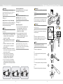
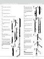
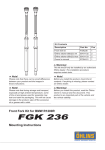
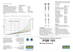
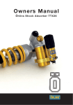
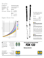
Set-up Data
Recommended set-up:
Rebound adjustment
Compression adjustment
Spring preload
Oil level Öhlins Front Fork fluid
13 clicks
1 turn
2 mm
150 mm
Part No. 01309-01
Recommended sag and ride height:
The measures should not differ from the
following recommendations:
Without rider:
Rear
5 - 15 mm (R1-R2)
Front
20 - 30 mm (F1-F2)
Before installing this product, check the
contents of the kit. If anything is missing, please
contact your nearest Öhlins dealer.
With rider:
Rear
25 - 35 mm (R1-R3)
Front
30 - 40 mm (F1-F3)
Kit Contents
Part No. Front fork kit
FGK133 Öhlins Sticker (60x23) white 00191-32
Öhlins Sticker (60x23) blue 00191-33
Force [N]
Diagram - Oil Level - Force
400
400
375
375
350
350
160mm oil lev
325
325
170mm oil lev
300
300
180mm oil lev
275
275
250
250
225
225
200
200
175
175
150
150
125
125
100
100
75
75
50
50
25
25
0
140mm oil lev
150mm oil lev
Warning!
This kit should only be installed by an authorized
Öhlins dealer. The installation procedure requires
certain tools.
190mm oil lev
200mm oil lev
210mm oil lev
Please note that during storage and
transportation, especially at high ambient
temperature, some of the oil and grease used for
assembling may leak and stain the packaging.
This is in no way detrimental to the product,
wipe off the excessive oil/grease with a cloth.
220mm oil lev
230mm oil lev
240mm oil lev
Warning!
Before installing this product, read the Öhlins
Owner’s Manual. The front fork is an important
part of your vehicle and will affect the stability.
0
0
10
20
30
40
50
60
70
80
90
100
110
120
Stroke [mm]
Öhlins products are subject to
continuous improvement and
development, therefore, although
these instructions include the most
up-to-date information available at
the time of printing, minor updates
may occur.
To find the latest information contact
your Öhlins distributor. Please
consult your Öhlins dealer if you
have any questions regarding the
contents in this document.
© Öhlins Racing AB. All rights
reserved. Any reprinting or
unauthorized use without the written
permission of Öhlins Racing AB
is prohibited.
Öhlins Racing AB
Box 722
S-194 27 Upplands Väsby, Sweden
Phone +46 8 590 025 00
fax +46 8 590 025 80
Front Fork Kit for Kawasaki ZX-6R
FGK 133
Part no. FGK133_3
Issued 2009-05-14
Mounting Instructions
www.ohlins.com
Pcs.
1
2
2
Safety Precautions
Adjustments
Note!
Warning!
The front fork is a very important part of the
vehicle and will therefore affect the stability.
Read and make sure that you understand the
information in this manual before you use this
product. If you have any questions regarding
installation or maintenance please contact your
nearest Öhlins dealer.
Safety Symbols
Öhlins Racing AB can not be held
responsible for any damage to the front fork,
vehicle, other property or injury to persons, if the
instructions for installing and maintenance are
not followed exactly.
The Safety Alert Symbol means: Warning!
Your safety is involved.
In this manual, mounting instructions and
other technical documents, important
information concerning safety is
distinguished by the following symbols:
Warning!
The Warning Symbol means: Failure to
follow warning instructions can result in
severe or fatal injury to anyone working with,
inspecting or using the front fork, or
to bystanders.
Warning!
This product was developed and designed
exclusively for a specific vehicle model and
should only be installed on the intended vehicle
model in its original condition as delivered from
the vehicle manufacturer.
Caution!
The Caution Symbol means: Special
precautions must be taken to avoid damage
to the front fork.
After installing this product, take a test ride
at low speed to make sure that your vehicle has
maintained its stability.
Note!
The Note Symbol indicates information that
is important regarding procedures.
Note!
Before riding, always make sure that the basic
settings made by Öhlins are according to
recommended Set-up Data. Contact an Öhlins
dealer if you have any questions about setting
up the front fork.
1
1. Spring Preload Adjuster. Adjust by
turning the nut on the top of the fork leg. Turn
clockwise to increase and counter clockwise
to decrease the spring preload.
2. Rebound Damping Adjuster. Adjust by
turning the screw with an allen key.
3. Compression Damping Adjuster. Adjust
by turning the screw, use proper tool.
2
To Reset
The adjusters have a normal right hand
thread. Turn the damping adjuster clockwise
to fully close (pos. zero [0]). To open, turn the
damping adjuster counter clockwise - count
the clicks or turns from fully closed until you
reach the recommended setting. See Set-up
data in this manual.
3
Caution!
Do not use force, delicate sealing surfaces can
be damaged.
When working on this product, always consult
your Vehicle Service Manual.
This Manual should be considered as a part
of the product and should therefore accompany
the product throughout its life cycle.
© Öhlins Racing AB. All rights reserved. Any
reprinting or unauthorized use without the written
permission of Öhlins Racing AB is prohibited.
Printed in Sweden.
Tools
Tool 1765-03
Tool 1797-07
Tool 0797-01
1
Decrease
6
Increase
How to install
1 - Remove Original Front Fork
Recommended Measures
Recommended measures for Free Sag and
Ride Height; see Set-up Data.
Warning!
Before riding, always ensure that the basic
settings made by Öhlins are intact. Take notes,
adjust in small steps and make only one
adjustment at a time.
Note!
Always check on the Öhlins web site www.ohlins.com or with your Öhlins dealer/ distributor for the latest information.
Step 1
Spring Preload - Free Sag - Ride Height
Spring preload is a crucial part of setting your
motorcycle since it affects the height of the
motorcycle and the fork angle.
Step 2
Adjust spring preload
1. If your measures differ significantly from
the recommendations in the Set-up
Data, adjust the spring preload. (See
Adjustments this manual).
2. If the ride height still differs from the
recommendations, you may need to
change to softer/harder spring. Contact
your Öhlins dealer for advise.
Note!
The following procedure should be performed on
a flat surface.
1. Put the motorcycle on a workstand so that
both wheels are off the ground and the
suspension is unloaded.
2. Mark, for example with a piece of tape, a
point immediately above the rear wheel
axle.
3. Measure the distance from the marked
point to a fixed point, for example the
wheel axle (R1).
4. Measure the distance from the bottom of
the outer tube to a fixed point, for example
the front wheel axle (F1).
5. Put the motorcycle on the ground so
that the front and the rear suspensions
are slightly compressed. Repeat the
measuring procedures (R2 and F2).
6. Sit on the motorcycle in normal riding
position, properly outfitted in your riding
gear. Repeat the measuring procedure (R3
and F3).
Warning!
Incorrect spring rate may result in a front
geometry that is either too steep or too flat.
This can result in a tendency of under or over
steering, that could seriously affect the handling
characteristics of the motorcycle.
Warning!
It is advisable to have an Öhlins dealer install the
front fork.
When installing, consult your Vehicle Service
Manual.
2
1
Put the motorcycle on a workstand so that
the front wheel barely touches the ground.
Warning!
Make sure the vehicle is securely supported so
that it will not tip.
1
3
2
Remove the front fender, brake caliper and
the front wheel.
3
Measure the position of the front fork:
Measure the distance from the top of the fork
leg to the top of the upper fork crown.
Note!
It is very important that the front fork is
reattached at the exact same position.
Screw
4
Release the spring preload.
5
Loosen the upper fork crown by loosening
the screws.
4
6
Loosen (do not remove) the top cap ½ turn.
7
Loosen the lower fork crown by loosening the
screws.
6
8
Remove the fork legs from the fork crowns.
1/2 turn
5
2
5
2 - Disassemble Original Front Fork
2.1
Remove the original top cap from the fork leg.
3 - Install Öhlins Front Fork Kit
3.8
Make sure the piston shaft is in the bottom
of the fork leg and that the outer fork leg is
in the bottom position. Measure the oil level
with a ruler. Recommended setting according
to chapter Set-up data and Diagram: Oil
level-force.
2.2
Remove the original cartridge from the fork
leg.
2.3
Turn the fork legs upside down to pour out
all oil.
1
Top cap
3
3.2
Remove the spring support, spring and the
preload tube.
3.3
Put the cartridge into the fork leg.
Top cap
3.10
Fasten tool 01765-03 on the top of the shaft.
Install the spring support by leading it over
the tool.
Spring
3.4
Tighten the cartridge with tool 01797-07 to
torque 20 Nm. Smear some loctite 243 on the
threads.
support
Spring
3.5
Remove tool 01797-07 and pour
approximately 0,5 litre Öhlins Front Fork fluid
into the fork leg.
Preload
tube
5
3.7
Remove the top cap from the fork leg.
Loctite
4
Spring
support
9
Spring
3.12
Open the rebound adjuster fully. Remove
the pull-up tool and install the top cap to the
shaft. Tighten with torque 15 Nm.
Preload
tube
3.13
Pull up the outer tube. Make sure the fork
leg is in a fully extended position. Use tool
00797‑01 to tighten the top cap. Tighten the
top cap with torque 10 Nm.
11
3.14
Set the spring preload, rebound and
compression adjusters according to
Adjustments and Set-up data in this
manual.
Spring
support
Top cap
12
3.15
Install the front fork legs into the fork crowns.
Tighten the upper fork crown with torque
20 Nm, and the lower fork crown with
torque 10 Nm.
13
Note!
It is very important that the front fork is in the
same position as before changing the fork kit!
3
XXX mm
10
3.11
Pull up the piston shaft with tool 01765-03
and grab the spring support with a 19 mm
wrench.
2
3.6
Open the rebound adjuster fully. Install the
top cap directly to the cartridge (no spring or
preload tube). Pull up the front fork outer tube
and screw it to the top cap. Handtighten
only. Pump out all air from the cartridge by
pulling the outer tube up and down 10‑15
times.
8
3.9
Put the preload tube and the spring on top of
the cartridge.
3 - Install Öhlins Front Fork Kit
3.1
Remove the Öhlins top cap from the shaft.
6
4