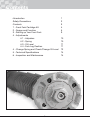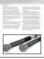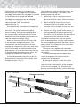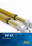
1
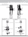
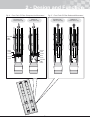
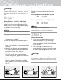
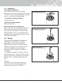
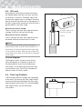
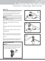
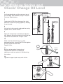
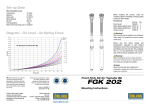
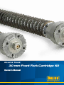
Road & Track
30 mm Front Fork Cartridge Kit
Owner’s Manual
Introduction
Öhlins Racing AB - The Story
It was the 1970’s, a young man named Kenth
Öhlin spent most of his spare time pursuing his
favourite sport: motocross.
Congratulations! You are now the owner
of an Öhlins Front Fork Cartridge Kit. More
than two hundred World Championships
and other major world titles are definitive
proof that Öhlins products offer outstanding
performance and reliability.
A careful observer, Kenth’s attention was
continually drawn to one specific detail motocross bikes had more engine power
than
their
suspension
could
handle.
It was not long before Kenth realised that better
performance could be achieved by improved
wheel suspension.
Every product has gone through rigorous testing
and engineers have spent thousands of hours,
doing their very best to use every possible
experience from our 30 years within the racing
sport. The product that you now have in your
possession is pure racing breed that is built to
withstand.
Öhlins Racing was established in 1976, and
just two years later the company won its first
World Championship title. Despite being in the
business for 30 years, the search for perfection
and new functions is still the main focus of the
company.
By installing this Front Fork Cartridge Kit on
your bike you have made a clear statement…
you are a serious rider with a focus on getting
the maximal handling ability and outstanding
feedback from your bike. Along comes the
fact that your Front Fork Cartridge Kit will be
a long lasting friend, delivering the very best
of comfort and performance every time you go
for a ride. Go explore!
1
Safety Precautions
Note!
Safety Symbols
The front fork is a very important part of the
vehicle and will therefore affect the stability.
Read and make sure that you understand
the information in this manual and the mounting
instructions before you use this product. If you
have any questions regarding installation or
maintenance please contact an Öhlins dealer.
In this manual, mounting instructions and
other technical documents, important
information concerning safety is
distinguished by the following symbols:
The Safety Alert Symbol means: Warning!
Your safety is involved.
Öhlins Racing AB can not be held
responsible for any damage to the front fork,
vehicle, other property or injury to persons, if
the instructions for installing and maintenance
are not followed exactly.
Warning!
The Warning Symbol means: Failure to
follow warning instructions can result in
severe or fatal injury to anyone working with,
inspecting or using the front fork, or
to bystanders.
Warning!
This product was developed and designed
exclusively for a specific vehicle model and
should only be installed on the intended vehicle
model in its original condition as delivered from
the vehicle manufacturer.
Caution!
The Caution Symbol means: Special
precautions must be taken to avoid damage
to the front fork.
After installing this product, take a test ride
at low speed to make sure that your vehicle
has maintained its stability.
Note!
The Note Symbol indicates information that
is important regarding procedures.
If the suspension makes an abnormal noise,
or the function is irregular, or if you notice any
leakage from the product, please stop the
vehicle immediately and return the product to
an Öhlins Service Centre.
Note!
When working on this product, always consult
your Vehicle Service Manual.
This Manual should be considered a part of
the product and should therefore accompany
the product throughout its life cycle.
© Öhlins Racing AB. All rights reserved. Any
reprinting or unauthorized use without the written
permission of Öhlins Racing AB is prohibited.
Printed in Sweden.
2
Contents
Introduction
Safety Precautions
Contents
1 - Front Fork Cartridge Kit
2 - Design and Function
3 - Setting up Your Front Fork
4 - Adjustments
4.1 - Adjusters
4.2 - Spring
4.3 - Oil Level
4.4 - Fork Leg Position
4 - Change Spring and Check/Change Oil Level
5 - Technical Specifications
6 - Inspection and Maintenance
3
1
2
3
4
5
9
10
10
11
11
12
14
14
1 - Front Fork Cartridge Kit
Introduction
The product in your hand is an artwork,
prepared by our dedicated craftsmen at
our facility in Upplands Väsby, Sweden.
Its predecessors have battled their way on
numerous race tracks in World Superbike,
Supersport, Superstock and AMA and the
legacy continues in your front fork. Thousands
of hours have been spent together with some of
the best teams in the world to find the optimal
design and functionality to give you as much
performance and comfort as possible. You will
feel the difference…be sure.
Our engineers that work on a daily basis with
the top riders in the world often hear the word
“feeling” and “control” when they debrief after
tests and races.
We wanted to pour as much of these
important factors into your front fork cartridge
kit and, as a result, the new 30 mm front
fork cartridge kit gives you improved “brake
support” and “tire feel” when riding. For all of
you that have your mind set on doing some
serious racing we have some really good news.
Of course we have improved the design so
that you easily can have it properly maintained
and every kit is individually tested with an
optimum setting, spring and top-out spring.
The new top-cap design will send a signal to
all curious spectators when you pull over next
to your favourite café or local race track… it’s a
signal that says that the owner of the bike has
made his choice to go straight for the podium.
Now we are raising the new 30 mm front fork
cartridge kit to a new level.
Design
The DNA of this new 30 mm front fork cartridge
kit originates in the most prestigious race
series in the world and the front fork cartridge
kit is weight optimized as a result of that fact.
We have used exclusive racing components
from our R&D department to increase the
performance of the front fork cartridge kit.
4
2 - Design and Function
The front fork cartridge kit is divided into
one compression cartridge and one rebound
cartridge. The compression cartridge is installed
in the left front fork leg and the rebound
cartridge in the right front fork leg. Marked
at the top cap is “COMP” for compression
adjustment and “REB” for rebound
adjustment (Fig. 1).
The compression and rebound cartridges are
both of the same design but works opposite
each other. To achieve rebound damping
force instead of compression damping force,
the cylinder tubes and the pistons are turned
opposite each other between the compression
and the rebound cartridges (Fig. 2).
When the front fork moves, the fluid inside
is forced to flow through the pistons. At a
compression movement the fluid is forced
through the compression shim stack and at the
same time through the rebound check valve.
And opposite, at a rebound movement the fluid
is forced through the rebound shim stack and
through the compression check valve.
The fluid displaced by the piston shafts are
directed either into or out of the cylinder tubes
through the holes. (Fig. 2)
Fig. 1 - Cartridges
The compression and the rebound pistons are
both of the same design. The pistons have
three flow paths for the fluid:
1. Bleed valve (Fig. 3 centre gray arrows).
Small orifice that creates a flow restriction
simply by being small.
2. Shim valve (Fig. 3 outer black arrows).
Fluid pressure has to deflect thin steel
washers (shims) to open up an orifice and
allow fluid to flow through it.
3. Check valve (Fig. 3 outer white arrows). A
spring preloaded shim that opens easily,
for return flow of fluid when the direction of
movement of the front fork changes.
The bleed valve and shim valve are used to
build up damping force. At slow stroke speeds
the percentage going through the bleed valve is
higher and at fast strokes the shim valve takes
care of most of the flow.
The check valve, together with the bleed
valve (since it can flow both directions), handle
return flows.
To control damping force the bleed valve
can be changed by the external adjuster,
compression and rebound.
By altering the stiffness of the shim stack
(number, thickness, diameter and shape) on the
shim valve the characteristics of the damping
action can be changed. This should only be
done by an authorized Öhlins service workshop.
Rebound Cartridge
Top cap
marked
“REB”
Cylinder tube
Compression Cartridge
5
Top cap
marked
“COMP”
2 - Design and Function
Fig. 2 - Schematic View
Compression Front Fork Leg
Rebound Front Fork Leg
Cylinder
tube
holes
Shim
stack
Check
valve
Piston
Piston
Check
valve
Shim
stack
Cylinder
tube
holes
Fig. 3 - Piston Oil Flow
Compression
Rebound
bleed valve flow
bleed valve flow
Shim stack
Check valve
Piston
shim valve flow
check valve
flow
Piston
check
valve
flow
shim valve flow
Check valve
Shim
stack
6
2 - Design and Function
Compression damping
Rebound damping
Compression front fork leg
When movement of the motorcycle causes
compression of the front fork (Fig. 4
compression movement), the fluid below the
compression piston is pressurized and goes
through:
• Compression shim valve
• Compression bleed valve
Rebound front fork leg
When the spring forces the front fork to extend
again (Fig. 5 rebound movement), the fluid
above the rebound piston is pressurized and
in a similar pattern as compression movement,
goes through:
• Rebound shim valve
• Rebound bleed valve
Rebound front fork leg
The pressure difference between the inside of
the front fork leg and above the rebound piston
causes the fluid to go through:
• Rebound check valve
• Rebound bleed valve (Small and insignificant
flow compared to the check valve)
Compression front fork leg
As similar the rebound front fork leg at a
compression movement, the pressure difference
between the inside of the front fork leg and
below the compression piston causes the fluid
to go through:
• Compression check valve
• Compression bleed valve (Small and
insignificant flow compared to the
check valve)
Displaced fluid
During compression movement, the piston
shafts enter the cylinder tubes and the
correspondingly displaced volume of fluid has
to flow out of the cylinder tubes through the
holes.
Displaced fluid
The fluid that was displaced by the piston
shafts is now pushed back into the cylinder
tubes by the pressure difference between the
inside of the front fork legs and above and
below the pistons.
7
2 - Design and Function
Fig. 4 - Front Fork Oil Flow Compression Movement
Compression
Front Fork Leg
Fig. 5 - Front Fork Oil Flow Rebound Movement
Compression
Front Fork Leg
Rebound
Front Fork Leg
Cylinder
tube
holes
Shim
stack
Piston
Check
valve
Check
valve
Piston
Shim
stack
Cylinder
tube
holes
8
Rebound
Front Fork Leg
3 - Setting up your Front Fork
Recommended Measures
If no other recommendations are given in the
Mounting Instructions follow the measures
below:
Warning!
Before riding, always ensure that the basic settings
made by Öhlins are intact. Take notes, adjust in
small steps and make only one adjustment at a
time.
Free sag/ Without Rider (R1-R2), (F1-F2)
Rear
5 - 15 mm
Front
20 - 30 mm
Step 1
Ride height/ With Rider (R1-R3), (F1-F3)
Rear
25 - 35 mm
Front
30 - 40 mm
Spring Preload - Free Sag - Ride Height
Spring preload is a crucial part of setting your
motorcycle since it affects the height of the
motorcycle and the fork angle. Before setting
the preload, measure the sag:
Note!
Always check on the Öhlins web site www.ohlins.com or with your Öhlins dealer/ distributor for the latest information.
Note!
The following procedure should be performed on a
flat surface.
Step 2
1. Put the motorcycle on a workstand so that
both wheels are off the ground and the
suspension is unloaded.
2. Mark, for example with a piece of tape, a
point immediately above the rear wheel axle.
3. Measure the distance from the marked
point to a fixed point, for example the wheel
axle (R1).
4. Measure the distance from the bottom of
the upper triple clamp to a fixed point, for
example the front wheel axle (F1).
5. Put the motorcycle on the ground so that
the front and the rear suspensions are
slightly compressed. Repeat the measuring
procedures (R2 and F2).
6. Sit on the motorcycle in normal riding
position, properly outfitted in your riding
gear. Repeat the measuring procedure (R3
and F3).
Adjust spring preload
1. If your measures differ significantly from
the recommendations in the Mounting
Instructions or the table above, adjust the
spring preload. (See chapter Spring Preload
in this manual).
2. If the ride height still differs from the
recommendations, you may need to change
to softer/harder spring. Contact your Öhlins
dealer for advise.
Warning!
Incorrect spring rate may result in a front geometry
that is either too steep or too flat. This can result
in a tendency of under or over steering, that could
seriously affect the handling characteristics of the
motorcycle.
9
4 - Adjustments
4.1 - Adjusters
• Spring preload adjuster Use a 14 mm wrench to turn the upper
adjustment screw. Maximum adjustment range
is 18 mm. One turn of the adjustment screw will
cause 1 mm change in spring preload.
Spring preload adjuster
• Compression damping adjuster
Left front fork leg.
• Rebound damping adjuster
Right front fork leg.
Adjust Compression and Rebound;
Use a 3 mm allen key. Adjustment range from
fully closed valve (clockwise) to fully open
valve (counter-clockwise) is about 20 “clicks”.
Recommended “clicks” from closed position
according to your mounting instruction for your
Front Fork Cartridge Kit.
Compression adjuster
4.2 - Spring
The spring recommended in the Mounting
Instructions is chosen after evaluations
performed on a test track according to
motorcycle characteristics for your specific
motorcycle model. Due to variations in ride
style, track conditions, body shape etc.
the spring is often a subject for additional
fine‑tuning.
Springs are available in 0.5 N/mm intervals
from 6.5 N/mm to 11.5 N/mm but the rate can
be set to 0.25 N/mm increments by using two
different rates. A method used on the race
track.
Rebound adjuster
Example:
Using 9.5 N/mm in the right front fork leg
and 10.0 N in the left front fork leg gives a
combined spring rate of 9.75 N/mm.
10
4 - Adjustments
4.3 - Oil Level
Compared to conventional type of front forks,
the upside down front forks are very sensitive
to variations in oil level. Therefore, adjust the
oil level with special care. A change in the front
fork oil level will not affect the air spring force in
the early stage of the movement, but will have a
greater effect in the later stage.
Öhlins Front Fork Fluid
When the oil level is raised:
The air spring in the later half stage of travel is
stronger, and thus the front fork harder.
The upper edge of the
outer front fork leg
When the oil level is lowered:
The air spring in the later half stage of travel is
lessened, and thus the front fork is softer.
Oil level
Note!
When measuring oil level; remove spring and
preload tube, make sure the shaft assembly is in
the bottom of the fork leg and that the outer tube
is in its bottom position. Measure the oil level with
a ruler. See set-up data and oil level-force diagram
in this folder.
Oil level diagram
The Diagram shows several curves for the
force that equals to a specific oil level. For
recommended oil level, see the Mounting
Instructions. If the Mounting Instructions was
not included in your Front Fork Cartridge Kit,
please contact an Öhlins dealer.
4.4 - Fork Leg Position
The Fork Leg Position changes the ride height
at the front. To measure the Fork Leg Position;
measure the distance between the outer tube
and the upper triple clamp. For recommended
Fork Leg Position, see the Mounting
Instructions.
Fork leg position
11
5 - Change Spring and
Check/ Change Oil Level
Warning!
This procedure requires high technical knowledge
and/or experience of working with front forks. If
you feel any insecurity regarding this procedure,
contact an Öhlins dealer for advice. See the
Vehicle Service Manual.
1
Note!
The following procedure is performed on front fork
legs installed in the vehicle.
2
1
Release the spring preload fully (counter
clockwise).
3
2
Loosen the upper triple clamp by loosening the
screws.
3
Loosen the top cap from the outer tube, use
tool 00797-08.
4
Remove the top cap from the shaft extension.
Use a 19 and a 14 mm wrench to loosen the
top cap.
4
5
Remove the spring support, the spring and the
preload tube. Check the oil level, see figure.
Check/Change Oil Level
Note!
We recommend you to check the oil level since
spring removal affects the oil level. Measure oil
level without spring or preload tube according
to chapter “Setting Up - Oil Level”.
XXX mm
12
5 - Change Spring and
Check/ Change Oil Level
6
Put the preload tube and the spring on top of
the cartridge. See available springs in chapter
Technical Specifications.
The marking
facing up.
6
7
7
Fasten tool 01765-03 on the top of the shaft
extension. Install the spring support by leading
it over the tool.
Tool
1765-03
8
Pull up the shaft assembly and grab the spring
support with a 19 mm wrench.
Spring
support
Preload
tube
9
Open the compression and rebound adjusters
fully. Remove the pull-up tool and install the top
cap to the shaft extension. Torque: 15 Nm.
10
Make sure the front fork leg is in a fully
extended position. Use tool 00797‑08 to tighten
the top cap to the outer tube.
Torque 10 Nm.
8
11
Set the spring preload, rebound and
compression adjusters according to
adjustments and set-up data in the Mounting
Instructions.
Spring
support
12
Tighten the upper triple clamp with 20 Nm.
19 mm
wrench
9
10
13
6 - Technical Specifications
Front Fork length
See specification card for your specific Front
Fork Cartridge Kit.
Available Springs:
Part No.
08790-65
08790-70
08790-75
08790-80 08790-85 08790-90 08790-95 08790-10 08790-05 08790-11 08790-15
Stroke
See specification card for your specific Front
Fork Cartridge Kit.
Free spring length
260 mm
Compression adjustment
Maximum open valve about 20 clicks.
Rebound adjustment
Maximum open valve about 20 clicks.
Spring Rate
6.5 N/mm
7.0 N/mm
7.5 N/mm
8.0 N/mm
8.5 N/mm
9.0 N/mm
9.5 N/mm
10.0 N/mm
10.5 N/mm
11.0 N/mm
11.5 N/mm
Oil Level
See specification card or Mounting Instructions
for your specific Front Fork Cartridge Kit.
Spring preload adjustment
0 - 18 mm (0 - 18 turns)
Spring rate
Please see specification card or Mounting
Instructions for your specific Front Fork
Cartridge Kit.
Caution!
Use only Öhlins high performance Front Fork
Fluid  (01309-01).
7 - Inspection and Maintenance
Note!
Preventive maintenance and regular inspection
reduces the risk of functional disturbance. If
there is any need for additional service, please
contact an authorised Öhlins service workshop.
Discarded Öhlins products should be handed over
to an authorized work shop or distributor for proper
disposal.
Service Intervals
This product is designed for racing use only.
Service and maintenance is recommended
every 10 hours.
14
Öhlins Owner’s Manual Front Fork Kit FGK | Part No. 07284-01_2 | Issued 2010-03-25 | © 2010 Öhlins Racing AB
Your Öhlins retailer:
Öhlins Racing AB
Box 722
SE-194 27, Upplands Väsby
Sweden
Phone: +46 (0)8 590 025 00
Fax: +46 (0)8 590 025 80
www.ohlins.com