1
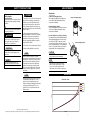
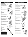
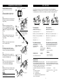
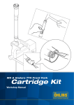
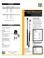
spring guide Brand Rider’s weight*SpringSpring rate kg/pounds Yamaha YZF 250 Yamaha YZF 450 70/154 75/165 80/176 85/187 90/198 95/209 08763-44 08763-44 08763-46 08763-46 08763-46 08763-48 70/154 75/165 80/176 85/187 90/198 95/209 08763-44 08763-46 08763-46 08763-48 08763-50 08763-52 N/mm 4,4 4,4 4,6 4,6 4,6 4,8 Owner’s Manual/ Mounting Instructions Öhlins front fork kit FGYA 893/ FGYA 894 for Yamaha YZF 250/ 450 2008 4,4 4,6 4,6 4,8 5,0 5,2 Please read before installing Öhlins Racing AB cannot be held responsible for any damage to the front fork kit, vehicle or injury to persons, if the instructions for fitting and maintenance are not followed exactly. Similarly, the warranty will become null and void if the instructions are not adhered to. This kit should only be installed by an authorized Öhlins dealer. The installation procedure requires certain tools. Before installing this front fork kit, please check the contents of the kit, listed below. If any part is missing, please contact your Öhlins dealer. maintenance Preventive maintenance and regular inspection reduces the risk of functional disturbance. Breather plug Make sure to ventilate the front fork at regular intervals: 1. Put the motorcycle on a workstand so that the front wheel is off the ground. Breather plug 2. Loosen the breather plug to release the excess pressure in the front fork. Recommended Service Intervals Every 25 hours. Make your service and maintenance according to Öhlins Work shop manual. Disposal Discarded Öhlins products should be handed over to an authorized Öhlins workshop or distributor for proper disposal. Öhlins Racing AB, Box 722, S-194 27 Upplands Väsby, Sweden. Phone +46 8 590 025 00. Fax +46 8 590 025 80. www.ohlins.com 07296-50_1 FGYA 893/ FGYA 894 Issued 2008-07-11 Öhlins Racing AB Annette Asph/ Jonas Mossberg * Rider’s weight: Rider wearing all riding equipment Kit Contents Front fork kit FGYA 893/894 (1) Sticker “TTX Cartridge” 00191-29 (2) Sticker “Öhlins” 00197-01 (2) O-ring 00338-10 (2) O-ring 00438-12 (2) Base plug TTX FG 15430-03 (2) Circlip 15440-01 (2) Spacer 2 mm 15443-02 (2) Spacer 3 mm 15443-03 (2) Owner’s Manual/Mounting Instr.07296-50 (1) NOTE! Oil and spring kit need to be ordered separately. For correct spring rate see spring guide recommendation. Use Öhlins fork oil only 01311-xx. In this manual Recommended tools Tool STD OEM top-cap tool Tool 20 mm socket (bottom plug) Tool 12 mm socket (shaft end adjuster housing) Tool Pliers for the security snap-ring Safety precautions Mounting instruction Set-up data Adjustments/ Diagram: Oil volume - Force Spring guide/ Maintenance SAFETY PRECA U TION S Safety signals Important information concerning safety is distinguished in this manual by following notations: This Safety alert symbol means: Attention! Your safety is involved! WARNING! Failure to follow warning instructions could result in severe or fatal injury to anyone working with, inspecting or using the suspension, or to bystanders. CAUTION! Caution indicates that special precautions must be taken to avoid damage to the suspension. NOTE! This indicates information that is of importance with regard to procedures. WARNING! 1. Installing a front fork kit, that is not approved by the vehicle manufacturer, may affect the stability of your vehicle. Öhlins Racing AB cannot be held responsible for any personal injury or damage whatsoever that may occur after fitting the front fork kit. Contact an Öhlins dealer for advice. 2. Please study and make certain that you fully understand the contents in the mounting instruction and the owner´s manual before handling this front fork kit. If you have any questions regarding installation procedures, contact an Öhlins dealer. 3. The vehicle service manual must be referred to when installing the Öhlins front fork kit. NOTE! Öhlins products are subject to continual improvement and development. Consequently, although these instructions include the most up-to-date information available at the time of printing, there may be minor differences between your suspension and this manual. Please consult your Öhlins dealer if you have any questions with regard to the contents of the manual. AD JUST M E N TS Adjustments Compression damping adjuster The compression adjuster is located at the top of the fork leg. Adjust by turning the slotted screw with a screwdriver. Compression damping adjuster Rebound damping adjuster The rebound adjuster is located at the bottom of the fork leg. Adjust by turning the slotted screw with a screwdriver. + - Reset the adjusters according to following: The adjusters have a normal right hand thread. Turn the damping adjusters clockwise to fully closed (pos. zero [0]). To open, turn counter clockwise, and count the clicks until you reach the recommended number. For recommended clicks see Set-up data. Static sag can only be changed with softer or harder spring rate. Rebound damping adjuster CAUTION! Do not use too much force, delicate sealing surfaces can be damaged. + NOTE! The total stroke of the front fork may differ from the original stroke, so that more or less of the steel tube will be visible when the fork is fully compressed. - DI A G R A M NOTE! During storage and transportation, especially at high ambient temperature, the oil and grease used for assembling may run out inside the packing and damage the expanded polystyrene packing material. This is not unusual and is in no way detrimental to the Öhlins product. Oil volume - Force Force 420cc 400cc 380cc 360cc © Öhlins Racing AB. All rights reserved. Any reprinting or unauthorized use without the written permission of Öhlins Racing AB is prohibited. Printed in Sweden. Stroke 6 MOUNTING IN STR UCTION S Changing springs (only) Top cap tool 3 This can be done on the motorcycle with Öhlins special tools. Make your service and maintenance according to Öhlins work shop manual. M OUN T I N G I NST R UC T I O NS ! WARNING! 1 1. It is advisable to have an Öhlins dealer to install the front fork kit. 2. Refer to the instructions in your vehicle service manual when changing the front fork. 1. Put the motorcycle on a work stand. 2. 3. When working on a raised vehicle, make sure that it is securely supported to prevent it from tipping. 4 Loosen the screws that hold the fork legs in the upper triple clamps. Security snap-ring Removing the original front fork 3. Upper triple clamp 1 Open up the top cap on the fork leg. Use a standard fork top cap tool. 4. Remove the security snap-ring in the bottom of the fork with a pair of pliers. Put the motorcycle on a workstand so that the front wheel is off the ground. Lower triple clamp 4 2 Front leg cover 6 Remove the front wheel and the brake caliper. 5. 5 Loosen the bottom end of the cartridge kit. 3 Bottom end 2 Measure the position of the front fork. Measure the distance from the top of the fork leg to the top of the upper triple clamp according to figure. 6. Install the tool 01890-01 (oil plug) by pushing it into the fork bottom. The plug will keep the oil in the fork while changing the spring. 2 Front wheel Brake caliper 4 Loosen the upper triple clamp by loosening the screws. 7. Remove the cartridge kit from the fork leg and change the spring. Note the preload washer (if any). 6 5 Loosen (but not remove) the top cap 1/2 turn. Use a standard tool from the motorcycle manufacture. Oil plug 8. Install the cartridge kit into the fork leg and push out the oil plug tool 01890-01. NOTE! 9. 7 Tighten the shaft end into the fork bottom with tightening torque 18 Nm. The preload washers must be below the spring, at the bottom end of the fork leg. Preload washer (optional) 10. Install the security snap-ring. Top cap 3 6 Loosen the lower triple clamp by loosening the screws. 7 Remove the front fork legs from the motorcycle. Fork leg Disassembling the original front fork NOTE! Spring If any oil is needed, use Öhlins Front Fork Oil 01311-xx only. CAUTION! The top cap should only be tightened by hand or maximum torque of 10 Nm into the fork leg. Cartridge kit 5 5 8 Follow your vehicles service manual to remove the original front fork kit from the front fork leg. Turn the fork leg upside down to pour out the oil. Clean your front fork internally thoroughly. 2 MOUNTING IN STR UCTION S O-ring 00438-12 Install the Öhlins front fork kit O-ring 00338-10 9 9 S E T-UP DATA Smear some red grease or similar on the orings and install them according to figure. Before riding your motorcycle, check sag and ride height according to Set-up data and Adjustments in this mounting instruction. To get the most out of your suspension component it is of great importance to make the correct settings for your weight - full riding equipment on. F1 10 10 Install and tighten the base valve plug into the fork bottom, use a 20 mm socket (tightening torque 45 Nm). Fork bottom R1 Base valve plug 11 Install the preload washer(s) 15443-xx (optional - see Set-up data, Spring preload), the recommended Öhlins spring (see Spring guide) and the cartridge kit into the standard fork leg. 11 Fork leg The preload washers must be below the spring, at the bottom end of the fork leg. Preload washer (optional) Tighten the cartridge shaft end into the base valve plug. Use a 12 mm socket (tightening torque 18 Nm). Spring 13 Install the security snap-ring at the shaft end groove according to figure. Cartridge kit 12 14 Cartridge shaft end/ Base valve plug Pour Öhlins front fork oil (01311-xx) into the fork leg according to the recommended settings. Oil volume range: 0,350 to 0,420 litre. 15 Tighten the Öhlins fork top cap gently. Use the standard top cap tool from the motorcycle manufacture. Handtighten only! 13 16 3 Rear suspension F1. Motorcycle on a stand with the R1. Motorcycle on a stand with the suspension fully extended = ............ suspension fully extended = ............. F2. Motorcycle on the ground without rider = ............ R2. Motorcycle on the ground without rider = ............ F3. Motorcycle on the ground with rider = ............ R3. Motorcycle on the ground with rider = ............ Free sag F1 - F2 = ............ Free sag R1 - R2 = ............ Ride height F1 - F3 = ............ Ride height R1 - R3 = ............ Recommended settings: Recommended sag and ride height: Rebound damping Compression damping Spring preload 12 click 12 click -5 to 8 mm (can be changed with washers 15443-02 and 15443-03) If no other recommendations are given in your vehicles manual follow the measures below: Oil volume for 250F: Oil volume for 450F: 0,370 litre 0,380 litre Without rider: Rear 30 ±10 mm (R1-R2) With rider: Front 40 ±10 mm (F1-F3) Rear 100 ±10 mm (R1-R3) The setup for zero (0) preload is calculated below. An increase of the spring length and/or an increase of the preload washer thickness give a corresponding increase of the preload. Free spring length: 455 mm Preload washer (15443-xx): 15443-03 (3 mm) The preload is calculated as: Top cap tool It is very important that the triple clamps are tightened to the correct torque. Motorcycle with rider on Front suspension Measure the spring length. The springs may differ in length which will affect the preload. The preload can be changed with the preload washers 15443-xx (installed before the spring). A negative preload of up to – 5 mm is possible, because the top-out spring then still gives a small compression load on the main spring. 15 NOTE! Motorcycle on the ground Spring Preload 17 Install the front fork legs into the triple clamps. Tightening torque - see your vehicle service manual. F3 R3 Use only Öhlins fork oil 01311-xx. Security snap-ring Check and set the rebound and compression valves click positions according to the recommended settings in Set-up data. R2 Motorcycle on a stand NOTE! 12 F2 Preload: A Free spring length B Preload washer thickness C Installed length for spring and preload washer A + B - C = Spring preload 4 0 mm