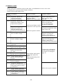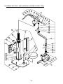
1
MODEL 096
DENTAL X-RAY
·Wall Mount Type.....................WK
·Room Mount Type...................RK
INSTALLATION
INSTRUCTIONS
(for USA & Canada)
REV.4
INDEX
PAGE
SECTION ONE : TECHNICAL DATA
[1] ELECTRICAL AND RADIATION DATA.......................................................... 3
[2] PHYSICAL DIMENSIONS................................................................................ 4
[3] TUBE HEAD THERMAL CHARACTERISTICS............................................. 5
SECTION TWO : PRE-INSTALLATION INSTRUCTIONS
[1] SUPPORT REQUIREMENTS............................................................................ 6
[2] ELECTRICAL REQUIREMENTS..................................................................... 6
[3] LOCATION OF COMPONENTS....................................................................... 7
SECTION THREE : INSTALLATION INSTRUCTIONS
[1] INSTALLATION REQUIREMENTS................................................................. 8
[2] UNPACKING...................................................................................................... 8
[3] ARM ASSEMBLY INSTALLATION.................................................................. 9
[4] HEAD ASSEMBLY INSTALLATION............................................................. 12
[5] CONTROL BOX INSTALLATION.................................................................. 12
SECTION FOUR : POST INSTALLATION INSPECTION
[1] ARM ASSEMBLY............................................................................................. 14
[2] BALANCE ARM ASSEMBLY......................................................................... 15
[3] HEAD POSITIONING...................................................................................... 15
SECTION FIVE : CONTROL IDENTIFICATION AND OPERATION
[1] CONTROL IDENTIFICATION........................................................................ 16
[2] FUNCTION OF CONTROLS........................................................................... 16
[3] OPERATING PROCEDURES.......................................................................... 18
[4] ERROR CODES................................................................................................ 19
SECTION SIX : POST INSTALLATION CONFIRMATION
[1] CONFIRMATION OF POWER SUPPLY VOLTAGE...................................... 20
[2] CONFIRMATION OF TUBE CURRENT........................................................ 20
[3] CONFIRMATION OF EXPOSURE WARNING LAMP & BUZZER............. 20
[4] CONFIRMATION OF LINE VOLTAGE REGULATION............................... 20
SECTION SEVEN : INITIAL SETTING
[1] FILM SPEED..................................................................................................... 21
[2] PRIORITY OF SELECTIONS.......................................................................... 23
[3] ELECTRONIC CHIME ON/OFF..................................................................... 23
APPENDIX ONE : CIRCUIT DIAGRAM . .......................................................... 23
APPENDIX TWO : PARTS IDENTIFICATION
[1] ,[2] ARM AND HEAD / CONTROL BOX ASSEMBLY................................. 24
[3] SLIDING SECTION / ARM AND HEAD ASSEMBLY OF RK TYPE........... 26
APPENDIX THREE : CERTIFICATION ............................................................ 28
CAUTION
This manual provides information and instructions for the installation, assembly calibration
and certification procedures for BELMONT BELRAY MODEL 096 dental x-ray.
The instructions contained in this book should be thoroughly read and understood before
attempting to install the X-ray unit. After the installation is complete, file this manual and
refer back to it when performing periodic maintenance.
--
SECTION ONE : TECHNICAL DATA
[1] ELECTRICAL AND RADIATION DATA
1. Focal point measurement............................................... 0.8 mm x 0.8 mm
2. Rated peak tube potential............................................... 70 kVp
3. Rated tube current.......................................................... 10 mA
4. Maximum rated peak tube potential.............................. 70 kVp
5. Rated line voltage.......................................................... 120 V AC
6. Line voltage range.......................................................... 108 V AC ~ 132 V AC
7. Range of line voltage regulation.................................... 2 ~ 5 %
8. Rated line current........................................................... 10.8 A at 70 kVp, 10 mA
9. Maximum line current.................................................... 11.9 A at 70 kVp, 10 mA
10. Exposure time.............................................................. 0.02 ~ 3 sec.
(ON and OFF are zero crossed.)
11. Timer accuracy............................................................. ± 1 pulse (1/60 sec.)
12. Inherent filtration......................................................... 1.3 mmAl Equivalent
13. Added filtration............................................................ 0.8 mmAl
14. Minimum filtration permanently in useful beam......... 2.1 mmAl Equivalent at 70 kVp
15. Nominal roentgen output
a. Distal end of regular cone............................................ 8.2 mGy/sec. + 30 %, - 40 %
b. Distal end of long cone................................................ 3.7 mGy/sec. + 30 %, - 40 %
(Data obtained by direct measurement in the useful beam)
16. Source to skin distance
a. Regular cone................................................................. 204 mm
b. Long cone..................................................................... 305 mm
17. Leakage technique factor............................................. 70 kVp / 0.16 mA
0.16 mA is maximum rated continuous current
for 10 mA with a duty cycle 1: 60
18. Duty cycle.................................................................... 1: 60 (0.5 sec. exposure with 30 sec. interval)
19. Maximum deviation of tube potential and tube current Pulse
Tube Potential Tube Current
+8
1st,2nd & 3rd 70 kVp
10 ± 2 mA
-11
+7
4th & Up
70 kVp
10 ± 1 mA
-10
20. Measurement base of technique factors
a. peak tube potential....................................................... Peak tube potential of conducting half cycle
b. tube current.................................................................. Average of tube current during one cycle of
line frequency
c. exposure time............................................................... Impulses of power line frequency
21. Half value layer............................................................ 1.5 mmAl over
22. Source to the base of cone distance............................. 81 mm
--
[2] PHYSICAL DIMENSIONS
(
) = mm
096-WK
220˚
600˚
4-1/8"
(104)
31-1/2"
(800)
9-1/8"(232)
Min. 34-5/8" (879)
Max. 77-15/16" (1979)
Max.75"
(1904)
10-5/16"(261)
46-11/16"(1185)
3-9/16"
(90)
096-RK
11"
(280)
300˚
Min. 19-1/4" (489)
Max. 62-9/16" (1589)
6-1/2"(165)
40-1/16"(1017)
40-5/8"
(1032)
SHORT CONE : 15-15/16"(404)
LONG CONE : 19-7/8"(505)
39"(990.6)
47-1/16"(1195)
4-3/16"
(106)
180˚
260˚
19-11/16"
(500)
19-11/16"
(500)
600˚
13-3/4"
(350)
4-3/16"
(106)
7-1/2"
(190)
3-9/16"
(90)
Max. 84-1/4"
(2140)
Max. 58-1/16"
(1475)
20"
(507)
Stroke 27-9/16"
(700)
15-3/4"
(400)
Max. 25-9/16"
(650)
--
30-1/2"
(775)
300˚
Stroke
7-7/8"
(200)
17-1/16"
(450)
3-11/16"
(93)
17-11/16"(322)
42-1/2"(1080)
40-5/8"(1032)
3-15/16"(100)
CENTER OF
ELECTRIC
Max. 46-7/8" (1190)
Stroke : 43 5/16" (1100)
48"(1219)
OPTION:
20" (500) or
12" (300)
Horizontal Arm
is available.
From 2004 July
[3] TUBE HEAD THERMAL CHARACTERISTICS
A. Interval between each exposure
The temperature inside of the tube head rises, when an exposure is made. The value of the heat
generated is measured in Heat Unit (HU), which is the product of tube potential, tube current and
exposure time. Excessive heat will be accumulated inside of the tube head, if the x-ray is used
without a proper cool down interval between each exposure. The excessive heat may damage the
x-ray tube, high voltage generator or both.
B. Duty cycle
To avoid the accumulation of excess heat in an effort to prolong the tube head life, a cool down
interval of 60 seconds or more must be allowed between each 1 second exposure. or a 30 second
cool down must be allowed between each 0.5 second (30 impulses) exposure.
C. Tube head cooling curve
1. Tube Housing cooling curve
Tube Housing Cooling Curve
0
ANODE THERMAL CHARACTERISTICS
0000
00
10
100
1
HU/
S
HU
/S
1000
Heat Storange (H.U.)
Heat Storange (KH.U.)
2. Anode thermal characteristics
14000
U/S
H
1
TUBE MODEL D-0
10000
6000
0
000
0
0
40
60
0
100
Time in Minutes
10
0
140
1
3. Maximum rating chart
FOCAL SPOT 0.8mm
0
Tube Current (mA)
0 kV
60 kV
0
0 kV
0 kV
90 kV
10
0.1
0.
0.
0. 0. 1.0
Load Time (sec.)
.0
--
.0
.0
Time in Minutes
4
6
SECTION TWO : PRE-INSTALLATION INSTRUCTIONS
[1] SUPPORT REQUIREMENTS
Control box:
When mounting the model 096 control box, the wall and mounting hardware must be sufficient to
withstand a 25 pound shear load.
Arm and head:
The MODEL 096 wall plate is designed for mounting on two 2 x 4 wood studs with 16 inches
centers. For other types of construction, the wall and mounting hardware must be sufficient to withstand
a 100 pound shear load and a 450 pound withdrawal force at each of the four mounting bolts.
The arm mounting bracket, part No.39, must be mounted to the wall plate using the bolts supplied with the
x-ray.
CAUTION :
If the MODEL 096 is to be mounted in a manner other than what is specified in this manual or if
the hardware to be used is other than what is supplied, the support capability of the wall and
the strength of the hardware must be checked and verified to be adequate.
[2] ELECTRICAL REQUIREMENTS
Power supply:
The MODEL 096 x-ray system will operate on a power supply of 120V AC,+12V AC,-12V AC (108V AC
to 132V AC).
A 3 wire GROUNDED circuit, separately connected to the central distribution panel with an over-current
protection device rated for 15 amperes.
Recommended wire size is 12 AWG BUT if the wire run distance is to exceed 50 feet 10 AWG is required.
For wire run distances in excess of 75 feet 8 AWG is required. Line voltage regulation must be within
2~5 % at 10.8 amps.
Interconnecting wiring, control box to arm and head assemblies:
6 conductor 12 AWG is recommended for wire run distances up to 50 feet. For wire runs between 50 and 75
feet 10 AWG is required and for wire run distances in excess of 75 feet 8 AWG is required.
Concealed wiring for WK type:
Concealed wiring is accomplished by bringing conduit and wires into (2) flush mounted junction boxes
located (1) behind the control box and (1) behind the arm mounting plate. Recommended heights for the
flush junction boxes are : 51 5/8" for behind control box and 44 1/2" for behind wall plate. Wiring done in
this manner should extend 12 inches beyond the wall surface to allow sufficient wire for connections.
FROM
POWER
SOURCE
Junction
Boxes
(1)
L N
4 6 Min 1AWG
Terminal Block
for Control Box
()
WALL
6 4 Pigtail for Arm
Mounting Bracket
NOTE:
All connections, workmanship and materials used must comply with the local codes.
--
[3] LOCATION OF COMPONENTS
A. Arm and head assemblies for WK type:
Using the information provided in FIGURE 1, determine the correct location for the installation of the arm
and head assemblies.
NOTE: State and local requirements supersede guide lines indicated below.
( ) : WITH LONG CONE
(66
"
(1904)
"
/
0
"
-1/
4
4-1/"
1"
(40)
1"
(0)
")
/16
1-1/16"
(104)
-1
220˚
(46-/16")
FIGURE 1
B. Control box :
When determining the location for the control box the following radiation requirements concerning
operator positioning must be considered. The operator must;
1. have full view of the patient.
2. have full view of kVp, mA, timer selections and exposure warning light.
3. be a minimum of 6 feet away from the patient.
4. be out of line of the useful beam of radiation or be positioned behind a protective device with X-ray
protection equivalent of 1 mm of lead.
--
From 2004 July
SECTION THREE : INSTALLATION INSTRUCTIONS
Within the installation and confirmation procedures are inspection/test steps which the installer must perform
to insure that the installation meets the manufacturer’s specifications. These steps require the installer to record
the necessary information onto the “ASSEMBLER’S INSTALLATION SECTION OF THE LIMITED
WARRANTY REPORT FORM” supplied, which must be returned to BELMONT along with the warranty
card.
[1] INSTALLATION REQUIREMENTS
Tools:
Standard tool kit including wire crimping pliers (AMP, “Super Champ” or equivalent).
1.5 mm, 2 mm, 3 mm and 5 mm allen keys.
Instruments:
Digital multimeter with an accuracy of 1%, capable of measuring 150 V AC and 10mA DC, and capable of
indicating true RMS value within 1 second.
Impulse counter, capable of registering 1 to 999 half-wave primary voltage impulses at a rate of 60 per
second over a range of 90 to 100 Vrms, 60 Hz.
Standard calculator.
POWER SUPPLY:
Prior to starting the installation inspect the power supply and confirm that the power supply is 120V AC,
+12V AC, -12V AC, and that the supply is a 3 wire GROUNDED circuit, separately connected to the
central distribution panel with an overcurrent protection device rated for 15 amperes (Refer to Page 6, [2]
ELECTRICAL REQUIREMENTS).
Record the voltage reading of power supply on “Assembler’s Installation Report”.
[2] UNPACKING
Unpack the entire contents of the shipping carton. Included within the shipping carton are:
Identification
Quantity
Head.............................................................................................................. 1/WK,RK
Regular Cone................................................................................................ 1/WK,RK
Long Cone.................................................................................................... (1)/WK (OPTION)
Control Box.................................................................................................. 1/WK,RK
Head key....................................................................................................... 1/WK,RK
Collar............................................................................................................ 1/WK,RK
Balance Arm................................................................................................. 1/WK
Balance Arm Wrench.................................................................................... 1/WK
Horizontal Arm W/ 2/Screw Cover.............................................................. 1/WK
Arm Mounting Bracket W/3 Machine Bolt (M8 x 20mm), 3/Bolt cap........ 1/WK
Wall Plate W/4 Coach Bolts, 3 bolts, Washers,7/bolt cap and template....... (1)/WK
Brake Screw (M6 x 6mm)............................................................................ 2/WK,RK
Brake Plug (Brass Plug)............................................................................... 2/WK,RK
Retaining Bolt (M6 x 35mm)....................................................................... 2/WK
Stopper Screw (M6 x 15mm)....................................................................... 1/WK,RK
Control Box Mounting Screw (ø5.8 x 32mm)............................................. 4/WK,RK
Brake Spring (ø5)......................................................................................... 1/RK
Base.............................................................................................................. 1/RK
Column......................................................................................................... 1/RK
Sliding Post................................................................................................... 1/RK
Swing Arm.................................................................................................... 1/RK
Gas Pump..................................................................................................... 1/RK
Seat............................................................................................................... 1/RK
Lag Bolt (ø8 x 45mm).................................................................................. 5/RK
Manual.......................................................................................................... 1/WK,RK
Inspect contents of shipping carton for damage or missing components.
--
[3] ARM ASSEMBLY INSTALLATION
[3-1] WK TYPE
The INSTRUCTIONS given below are for mounting the arm and head assembly on two 2 X 4 wood studs
with 16-inch centers. Should the MODEL-096 be mounted in a manner other than what is specified here,
the wall and the strength of the hardware used must be checked and verified as being adequate to withstand
a 100 pound shear load and a 450-pound withdrawal force at each of the four mounting bolts.
When using concealed wiring, a flush mounted junction box with the necessary conduit and wiring must be
pre-installed at 40 5/8 inches from the floor and centered between the two studs (refer to template).
A. WALL PLATE (FIGURE 2):
Level(b)
1. Tape the wall mount plate template to the wall, positioning it
Level(a)
so that the holes are aligned with the vertical 2 X 4" stud.
NOTE: In no instance is the wall mount plate, or the arm
mounting bracket, to be a single stud.
Coach Bolt
Bolt Cap
2. Mark the hole locations.
3. Using a 3/16" drill, drill a pilot hole approximately 2" deep for
each plate bolt. CAUTION: Do not use larger dia. drill.
The electrical wire access hole should be predrilled using the
Access Hole
height from the floor specified on the mounting template.
4. Place the wire through the hole into the stud mount wall plate
and mount the plate to the stud with 4 coach bolts supplied.
DO NOT FULLY TIGHTEN BOLTS.
5. Holding plate firmly against the wall, place a level(a) upright
FIGURE 2
on the surface. If the wall is not plumb, use shims behind
the plate to level.
6. Place a level(b) across top edge of wall plate, level and tighten bolts securely.
NOTE: Final leveling of wall plate is described on page 13.
7. Put bolt cap to each head of bolt.
B. ARM MOUNTING BRACKET (FIGURE 3):
1. Remove access cover from bottom of arm mounting bracket. Snake electrical interconnecting wires
through bracket and out access hole.
2. Using M 8 X 20 mm bolt with washers in lower mounting hole and two M 8 X 20 mm bolts in top
mounting holes, mount arm mounting bracket to wall plate. DO NOT FULLY TIGHTEN.
3. Placing level across top edge of arm mounting bracket, level bracket then tighten bolts securely.
4. Put the bolt cap to each head of bolt.
NOTE: Final leveling of wall mounting bracket is described on Page 13.
FIGURE 3
Level(b)
M x 0Bolt
Access Hole
Washer
Bolt Cap
Access Cover
C. If wall plate is not used, other optional, special, wall plate for "pas thru" (4X4") installation must be installed.
--
D. HORIZONTAL ARM (FIGURE 4):
Pull String
1. Cut pull string on horizontal arm. DO NOT REMOVE STRING.
ALLOW ONE END TO EXTEND BEYOND MALE BARB
AND THE OTHER END TO EXTEND BEYOND THE
FEMALE MOUNT.
Thrust Washer
2. Place a thrust washer over the hole of arm mounting bracket,
Retaining Bolts
and insert male barb into arm mounting bracket, allowing pull
Brake Screw
string to extend through access opening on bottom of the arm
mounting bracket.
Brake Plug
3. Insert two retaining bolts securely into upper threaded holes of arm
mounting bracket and tighten securely.
FIGURE 4
IMPORTANT: The retaining bolts must securely engage the annular
groove horizontal arm, the removal of the retaining bolts will allow the
horizontal arm to rise vertically, and out of, the arm mounting bracket.
DO NOT FULLY TIGHTEN.
4. Insert brake plug then brake screw(M6 x 6mm) into the lower threaded hole of the arm mounting bracket.
5. Place a level on the horizontal arm and confirm that the arm is level in its left and right swing positions.
NOTE: Final leveling of horizontal arm is described on Page 13.
E. BALANCE ARM ASSEMBLY (FIGURE 4a):
WARNING:
DO NOT RELEASE ARM HOLDING BAND UNTIL THE X-RAY HEAD HAS BEEN INSTALLED.
BALANCE ARM ASSEMBLY IS SPRING LOADED AND CAN CAUSE EQUIPMENT DAMAGE AND
INJURY IF NOT HANDLED IN THE PROPER MANNER.
1. DO NOT REMOVE ARM HOLDING BAND.
2. Secure pull string to cable and pulling the opposite
end, snake cable through horizontal arm and arm
mounting bracket.
3. Insert brake plug then brake screw (M 6 X 6 mm)
into the horizontal arm collar.
DO NOT FULLY TIGHTEN.
4. Remove end cap screw and open end cap.
5. Insert stopper screw into upper threaded hole inside
horizontal arm and tighten securely.
CAUTION: If stopper screw is not tightened
securely, the scissors arm can move vertically up
and out of the horizontal arm
6. Cut cable and interconnecting wires to a workable
length. Strip 3/8" of wire insulation from each lead.
With wire crimping pliers use supplied wire nuts
to make wire connections.
7. Insert connected wires into the arm mounting
bracket and secure the access cover to the bottom
of the arm mounting bracket.
8. Secure end cap with end cap screw, and place a
screw cover.
- 10 -
Arm Holding Band
Brake Plug
Brake Screw
End Cap
Screw Cover
End Cap Screw
Stopper Screw
Access Cover
Access Cover Screw
FIGURE 4a
From 2004 July
[3-2] RK TYPE (FIGURE 5)
1. Fix the base on the floor with lag bolts (supplied) or
with appropriate means.
Brake Screw
Brake Spring
Brake Plug
CAUTION :MAKE SURE THE BASE IS FIXED ON THE FLOOR FIRMLY.
Swing Arm Stopper Screw
2. Insert the sliding post with column cover into the
column.
3. Install the column on the base with mounting bolts. Make it vertical with adjusting bolts.
4. Put the thrust washer to top of the sliding post and
install the swing arm assembly to sliding post.
5. Set the stopper screw into lower threaded hole of
swing arm 2.
6. Set the brake plug then brake spring and brake
screw into the upper hole of swing arm 2.
Tighten the brake screw IF ARM DRIFTS.
DO NOT FULLY TIGHTEN.
Thrust Washer
Swing Arm 1
Sliding Post
Column Cover
Column
Cable Guide
Backrest
Cushion
Cable
Mounting Bolt
Adjusting Bolt
Gas Pump
7. Run the cable from swing arm 1 through a cable
guide.
8. Slide up the backrest cushion to the top of column.
9. Insert the gas pump into the gas pump bracket. Mount the seat on the gas pump.
10. Refer to page 12 for Head assembly installation.
11. Refer to page 13 for Control box installation.
12. Perform the post installation inspection.(page 14)
- 11 -
Seat
Gas Pump
Bracket
Lag Bolt
Base
FIGURE 5
[4] HEAD ASSEMBLY INSTALLATION (FIGURE 6):
Arm Holding Band
1. Remove a screw (a) on arm collar, and place the arm
collar over the stopper ringon the head shaft.
(Direction of arm collar is shown in FIGURE 6.)
Balance Arm
2. Remove the yoke inside cover by loosening screw(b).
3. Making sure the stopper ring and arm collar is placed
on the head shaft, insert the wirings of balance arm
through the head shaft to the head yoke.
4. Insert the head shaft into balance arm assembly, and
while holding the head in position, install head key
securely into retaining groove.
5. Slide the arm collar upward to proper position and
secure it in place with a screw (a).
Balance Arm
Wiring
Arm Collar
Head Key
1mm
mm
(a)
Head Shaft
Stopper Ring
Head Yoke
(b)
Terminal
6. Loosen 5 screws on the terminal using a small dia.
screw driver, and insert the wirings of balance arm
assembly into the terminal according to the color. (FIGURE 6-1)
Yoke Inside
Cover
7. Retighten the screws on the terminal and confirm that
the wirings are fixed on the terminal.
FIGURE 6
8. Remove M5 Phillips head screw from earth terminal
and secure No.8 wiring together to earth terminal.
Small Diameter
Screw Driver
9. Reattach the yoke inside cover with a screw.
10. Remove arm holding band.
[5] CONTROL BOX INSTALLATION
3
4
5
6
7
8
Blue
Brown
Red
Yellow
Gray
Green/Yellow
Wi
ri
Ar ngs
m of
As Ba
4
se lan
mb ce
6
ly
Earth Terminal
FIGURE 6-1
The wall and the strength of the hardware used must be checked and verified as being adequate to
withstand a 25 pound shear load.
A flush mounted junction box with the necessary conduit and wiring must be pre-installed at 51 5/8" from
the floor.
NOTE: Refer to the control box template, and:
1. Be certain the electrical wire entry hole is aligned with the junction box.
2. That there is adequate support in the wall to secure the control box.
- 12 -
From 2004 July
A. CONTROL BOX - MOUNTING (FIGURE 7):
1. Tape the control box template to the wall at the recommended height.
1a. Confirm relationship of access hole in for the electric wires with the entry hole for the wires in the back
of the control box.
2. Using a 3/32" drill, drill a pilot hole 2" deep for each mounting screw.
2a. The method of drilling the pilot hole and, the hardware use to secure the control box depend upon the
structure.
3. Drive two wood screws into upper two holes remaining about 3/4" undriven. (Fig.7a)
4. Remove two M3 Phillips head screws from top of the control box and open front panel. (Fig.7b)
5. Remove a restriction plate. (Fig.7c)
6. Snake power supply cable lines and interconnecting wires through access hole in back panel.
7. Hook the control box chassis to wood screws driven in step 3 above through two mounting holes
on upper side of chassis. Tighten screws slightly.
8. Attach two wood screws to mounting holes on lower side of back panel. (Do not fully tighten.) (Fig.7d)
9. Placing level across top edge of the control box, level, then tighten four screwes securely.
a
c
b
d
FIGURE 7
B. CONTROL BOX, WIRING (FIGURE 8-a & 8-b)
WARNING: MAKE SURE THE POWER SUPPLY IS TURNED OFF AT THE CENTRAL
DISTRIBUTION PANEL.
1. Strip approximately 3/8" of insulation off the power supply leads and interconnecting cables.
2. Following wiring diagram, connect those wires to the terminal block of control box.
3. Set the restriction plate to the original place.
GREEN/YELLOW
BLUE(WHITE)
From
Power
Source
BROWN(BLACK)
Junction Boxes
L N
4 6 Terminal Block
for Control Box
6
4
Pigtail for Arm
Mounting Bracket
WALL
BLUE
BROWN
RED
YELLOW
GRAY
GREEN/YELLOW
FIGURE 8-a
L
N
- 13 -
4
6
FIGURE 8-b
C. CLOSING FRONT PANEL (FIGURE 9).
CAUTION: BEFORE CLOSING THE FRONT PANEL, PERFORM POST INSTALLATION CONFIRMATION (PAGE 20 ).
1. Confirm all the post installation confirmation are performed.
2. Close the front panel and secure two M3 phillips head screws on the top panel.
FIGURE 9
SECTION FOUR: POST INSTALLATION INSPECTION
[1] ARM ASSEMBLY
1. Incorrect levelling of the wall bracket can cause arm drift. First, check level with arms in position #l . If not correct, bracket must be adjusted by placing shims behind the wall plate (FIGURE 10-a).
IMPORTANT:
If the end of the horizontal arm #1 is pitched below level, then the tubehead will drift away from the wall.
If the end of the horizontal arm #1 is pitched above level, then the level arm will require only minimum
adjustment of brake (friction) screw.
2. Check level in position #2. If not correct, adjust as follows: (FIGURE 10-b)
a) Remove bolt caps on mounting bolts.
b) SLIGHTLY loosen two top mounting bolts.
c) Shift the bracket left or right up to the arms arc accurately levelled.
d) Move the horizontal arm to position #1.
e) Fully tighten two top mounting bolts.
f) Fully tighten bottom mounting bolt.
g) Put the bolt cap to each head of mounting bolt.
NOTE: SLIGHT TENDENCIES TO DRIFT CAN BE CORRECTED BY TIGHTENING
BRAKE SCREWS IN HORIZONTAL ARM AND/OR WALL BRACKET.
DO NOT TIGHTEN BEYOND WHAT IS REQUIRED TO PREVENT DRIFT.
Top Mounting Bolt
#
Bolt Cap
LEVEL
LEVEL
#1
Brake Screw
Wall error adjustment;
installshimsbehind
thewallplate
Bottom Mounting Bolt
FIGURE 10-b
FIGURE 10-a
- 14 -
[2] BALANCE ARM ASSEMBLY
1. Place the balance arm assembly into position.
2. If either balance arm drifts either higher or lower from the set position, remove the spring adjuster covers
and with the supplied wrench adjust the balance arm springs (FIGURE 11).
more tension
TIGHTEN
Cover
less tension
LOOSEN
Adjustment Nut
Balance Spring
FIGURE 11
[3] HEAD POSITIONING
A. Place head into position.
B. If head drifts from the set position, adjust the brake screws according to the following procedures.
(FIGURE 12)
1. Remove the yoke outside cover by loosening cover screw.
2. Adjust 6 brake screws using phillips screw driver.
3. After adjustment, reattach the yoke outside cover with the cover screw.
Phillips Screw Driver
Yoke Outside Cover
Brake Screw
Cover Screw
FIGURE 12
- 15 -
SECTION FIVE : CONTROL IDENTIFICATION AND OPERATION
[1] CONTROL IDENTIFICATION
2
MODEL 096 0kVp 10mA
W A R N I N G
THIS X-RAY UNIT MAY BE DANGEROUS
TO PATIENT AND OPERATOR UNLESS SAFE EXPOSURE FACTORS
AND OPERATING INSTRUCTIONS ARE OBSERVED.
4
9
7
6
5
13
14
15
8
12
11
10
3
T1
T2
T3
T4
T5
a b
P
C
c
F
16
1
(1) Main Power switch
(2) Ready Lamp
(3) Exposure Time Adjusting Sw.
(Up)
(4) Exposure Time Adjusting Sw.
(Down)
(5) Tooth Selection Switch (T1)
(6) Tooth Selection Switch (T2)
(7) Tooth Selection Switch (T3)
(8) Tooth Selection Switch (T4)
(9) Tooth Selection Switch (T5)
(10) Patient Size Selection Switch
(11) Cone Type Selection Switch
(12) Film Speed Selection Switch
(13) Exposure Time Display Window
(14) Exposure Warning Light
(15) Exposure Switch
(16) Technical Switch
[2] FUNCTION OF CONTROLS
1
Main Power switch
Pushing right side of this switch energizes the x-ray unit.
(Ready lamp and pre-selected lamps for patient size, cone type and film speed illuminates.)
It is recommended to keep this switch OFF when the unit is not in use in order to prevent an accidental exposure.
2
Ready Lamp
This lamp lights when the line voltage is within operable range.
When this lamp is not on, exposure can not be made.
3
4
Exposure Time Adjusting Switches
By momentarily pushing (or ) switch, exposure time displayed increases (or decreases) by one
step. By keeping the switch depressed more than 2 sec., exposure time displayed increases (or decreases) continuously until the switch is released.
5 ~ 9
Tooth
Selection Switch (T1 ~ T5)
Pushing one of these switches set the exposure time automatically in combination with following
10 ~ 12 .
5
T1
: Incisor of Mandible
6
T2
: Incisor of Maxilla, Cuspid & Premolar of Mandible
T3
: Cuspid & Premolar of Maxilla, Molars of Mandible, Bitewing
7
8
T4
: Molars of Maxilla, Bitewing Molars
9 T5 : Occlusal
- 16 -
10 Patient Size Selection Switch
Pushing this switch alters the selection of patient size (small -> medium ->large -> small) and sets
the exposure time accordingly.
11 Cone Type Selection Switch
The exposure time corresponding to the cone type being used (Standard Regular Cone or Optional
Long Cone) can be selected by this switch.
12 Film Speed Selection Switch
Three types of film speed can be registered. Pushing this switch momentarily indicates the film
speed number being selected in exposure time display window 13 .
Depressing the switch for more than 2 seconds alters the film type being selected.
NOTE : Setting or adjusting the exposure time manually (with
5 ~ 12 functions.
or
switch) supersedes
13 Exposure Time Display Window
Normally the exposure time selected is displayed.
1. E.00 ~ E.12 :Error code [See page 19 of this manual]
2. F.00 ~ F.15 :Film type [See page 21 & 22 of this manual]
3. Tube Current:The tube current of the last pulse of the exposure can be displayed if the exposure
switch is kept depressed after exposure is over and technical switch 16 is depressed.
4. bu.0, bu.1 :Buzzer ON/OFF when a switch is activated. [See page 23 of this manual]
5. FIn
:Confirmation of tube current [See page 20 of this manual]
6. PH.0 ~ PH.F:To adjust tube current at beginning of exposure [Refer to service manual]
7. EP.0 ~ EP.F :To adjust tube current when stabilized [Refer to service manual]
8. Pt.0 ~ Pt.F :To adjust preheat time [Refer to service manual]
14 Exposure Warning Light
Illumination of this light indicates the unit is producing x-radiation.
15 Exposure Switch
Deadman Type exposure switch. When making an exposure, depress this switch and keep it depressed until the exposure warning light 14 and the audible warning terminate.
Failure to keep this switch depressed will result in premature termination of the exposure.
16 Technical Switch
This switch is exclusively for the installer and service personnel. It is used for following purposes:
1. The tube current (mA) of the last pulse of the exposure can be displayed in exposure time display
window 13 if the exposure switch is kept depressed even after the exposure is over and this technical switch is depressed. Display will return to exposure time when the exposure switch is released.
2. Priority of selection (Patient Size, Cone Type, Film Speed) can be changed when the main power
switch is turned on while this switch is depressed. [See section Seven of this manual]
3. Memorizing : After setting film speed, priority of selection and/or buzzer ON/OFF, this switch is
used for memorize these settings. [See section Seven of this manual.]
- 17 -
[3] OPERATING PROCEDURES
1.
Turn ON the main power switch
2.
Confirm that ready lamp 2 is illuminated.
NOTE: The ready lamp will not illuminate unless the incoming line voltage
is correct and within the x-ray’s operable range.
3.
Select the appropriate tooth type( 5 ~ 9 ), and confirm if the pre-selected
conditions (patient size 10 , cone type 11 and film speed 12 ) are suitable
for radiographing.
1
.
NOTE: To manually set the exposure time, depress either manual exposure
time adjust switch( 3
or 4 ) until the desired exposure time
is displayed in exposure time display window 13 . While the unit is in
manual mode, other selection switches( 5 ~ 12 ) do not affect
exposure time. (All the tooth selection lamps are off.)
To return to the automatic exposure time selection mode, depress any
one of tooth selection switches.
4.
Depress the exposure switch 15 . When the exposure switch is depressed,
the exposure warning lamp 14 illuminates and the audible warning sounds.
Do not release the exposure switch until the audible warning and the
warning lamp terminate. Failure to keep the switch depressed will result
in the exposure being terminated prematurely.
5.
To continue to radiograph other teeth, just select appropriate tooth
selection switch.
IMPORTANT : To protect x-ray tubehead from heat accumulation,
wait for 60 times of exposure time between exposures.
[Ex. 30 second wait interval for each 0.5 sec.(30 impulses) exposure]
6. After use turn OFF the main power switch
exposures.
1
in order to prevent accidental
NOTE : If the unit is left over 8 minutes without being operated and the
main power switch is kept on, figure 1 runs through the exposure time
display window. This does not mean that a malfunction of the unit has
occurred, but saves energy. The unit returns to normal condition by
pressing any one of the switches except the exposure switch.
- 18 -
[4] ERROR CODES
When abnormal condition exists in the unit, or malfunction occurs, error code
is displayed in exposure time display window.
Please refer to the table below.
Error Condition
code
E.00 Exposureswitchwas
releasedbeforethe
exposureterminates.
E.01
E.02
Exposureswitchwas
depressedwithin10sec.
ofpreviousexposure.
Exposureswitchwas
depressedwithin3sec.
afterthemainpower
switchhasbeenturnedon.
Linevoltagewaslessthan
90%ofratedvoltage.
E.03
Linevoltagewasmorethan
110%ofratedvoltage.
E.04
Excesscurrentduring
exposure.
Tubecurrentofthelast
pulsewaslessthan7.5mA.
Tubecurrentofthelast
pulsewasmorethan
12.5mA.
Tubecurrentduringexposurewaslessthan5mA.
Tubecurrentduringexposurewasmorethan
15mA.
Malfunctionofthe
microcomputer.
ExposureswitchorexposurecircuithadbeenON,
whenmainpowerswitch
isturnedon.
Tubecurrentisdetected
duringpre-heatingperiod.
Tubecurrentisdetected
whenmainpowerswitch
isturnedon.
E.05
E.06
E.07
E.08
E.09
E.10
E.11
E.12
Steptobetaken
Possiblesolution
Allthetoothselection
Releaseexposureswitch
switchesblink.
afterexposurelamp
Depressoneoftheswitch. turnsoff.
There is to be an "wait"
intervalof60times
ofexp.timebetween
A10seconddelayisbuilt successiveexposures.
inbetweeneachexposure. Exposureswitchshould
bedepressedaftertheready
lampcomesON.
Releaseexposureswitch.
Iflinevoltageisless
than90%ofratedline
voltage,correctitby
usingstep-uptransformer.
Iflinevoltageismore
than110%ofratedline
voltage,correctitby
usingstep-downtransformer.
Turnoffthemainpower
switchandwaitfora
while.
Turnonthemainpower
switchagain.
Conducttheconfirmation
oftubecurrentdescribed
insectionsix,item[2]on
page20.
Refertotheservicemanual.
- 19 -
SECTION SIX : POST INSTALLATION CONFIRMATION
[1] CONFIRMATION OF POWER SUPPLY VOLTAGE
As specified in Electrical Requirements (Page 6), power supply voltage must be within the operable
range of 108~132V AC. Confirm the power supply voltage again before turning on the unit.
1.Open the front panel of control box by loosening two screws on top of the control box.
2.Set the range of digital multi meter at 200V AC, connect probes of multimeter to L and N of
terminal block of control box.
3.Confirm that the reading is 120V ± 10% (108~132V AC).
NOTE : 096 X-ray can not be operated unless the power supply voltage is within this range.
[2] CONFIRMATION OF TUBE CURRENT
Model 096 x-ray incorporates self diagnose system to check if the tube current is within specified
range both at the beginning of exposure and during stabilized period.
1.While depressing tooth selection switches T1, T4 & T5 together, turn on the main power switch.
2.Exposure time of 0.50 is displayed and ready light is on.
[If not, turn off main power switch and repeat 1.]
Then release T1, T4 & T5 switches.
3.Make an exposure by depressing hand exposure switch.
WARNING: X-RADIATION IS GENERATED FOR 0.5 SEC.
4.Confirm that "F I n" is displayed at exposure time display window.
Then, turn off the main power switch.
5.If "PH. " and "EP. " are displayed alternately, follow Step 6 through 8 below.
6.When "PH. " and "EP. " are displayed alternately, leave the unit for about 30 seconds until
display returns to "0.50". Then make an exposure again and confirm that "F I n" is displayed.
7.Repeat Step 5 & 6 until "F I n" is displayed.
8.Record final PH & EP values in "Assemblers Installation Section of Limited Warranty Report Form" if
procedures in Step 5 through 7 are performed.
[3] CONFIRMATION OF EXPOSURE WARNING LAMP & BUZZER
A. EXPOSURE WARNING BUZZER
1. Make an exposure and confirm that the exposure warning buzzer located within the control box
is activated during the entire exposure.
B. EXPOSURE WARNING LAMP
Exposure warning lamp is located on the front panel of the control box,
1. Make an exposure and confirm that the warning lamp illuminates during the exposure.
[4] CONFIRMATION OF LINE VOLTAGE REGULATION
1.Make sure that main power switch is "OFF".
2.Open the front panel of control box by loosening two screws on top of the control box.
3.Set the range of digital multi meter at 200V AC, connect probes of multimeter to L and N of
terminal block of control box.
4.Turn the main power switch on, and set the exposure time at 2.00 sec. with manual switch .
5.Record the no-load line voltage (VN) indicated by the multimeter before exposure.
6.Make an exposure and record the load voltage (VL) indicated by the multimeter during exposure.
WARNING : X-RADIATION IS GENERATED FOR 2 SECONDS.
NOTE: Read the multimeter when the value is stabilized (about one second after exposure).
7.Calculate line voltage regulation R (%) in the formula below:
R =
VN - VL
VL
X 100 Record this value in "Assemblers Installation Report".
NOTE: LINE VOLTAGE REGULATION MUST NOT EXCEED THE RANGE OF 2~5%.
IF IT IS GREATER THAN 5%, THE SIZE OF THE POWER SUPPLY WIRES MUST BE
INCREASED. REFER TO THE POWER SUPPLY REQUIREMENTS OUTLINED ON
PAGE 5 TO DETERMINE THE CORRECT WIRE SIZE NECESSARY.
- 20 -
SECTION SEVEN : INITIAL SETTING
[1] FILM SPEED
As factory installation, following three kinds of film speed are registered to be selected by
Film Speed Selection Switch :
a = Film speed No. F.09 (equivalent to ISO speed group "D", or Kodak Ultra-Speed film)
b = Film speed No. F.04 (equivalent to ISO speed group "F/E", or Kodak InSight film)
c = Film speed No. F.02 (equivalent to ISO speed group "F")
Including these three, Model 096 can provide 16 different types of film speed and any three of them
can be registered for easy selection.
If the doctor uses different speed of film, or prefers darker (or lighter) radiograph, substitute speed
can be registered as follows:
1.While depressing technical switch 16 , turn on the main power switch
and F.09 is displayed in exposure time display window 13 .
Then, release technical switch.
1
. Film type lamp "a" is lit,
2.By depressing
switch (or switch), increase (decrease) film speed number until desired number
is displayed. [Refer to Exposure Time Table on next page.]
3.Depress technical switch 16 , an electronic chime sounds and the selected film speed number is
registered at film type "a".
4.Turn off the main power switch.
5.If different film speeds are to be registered at "b" and "c", depress "F"switch 12 after step 1 above
to light the appropriate film type lamp, and repeat steps 2 & 3.
- 21 -
TABLE 1 : FILM SPEED AND EXPOSURE TIME (REGULAR CONE)
Patient Size
Tooth
F. 00
F. 01
F. 02
F. 03
F. 04
F. 05
F. 06
F. 07
F. 08
F. 09
F. 10
F. 11
F. 12
F. 13
F. 14
F. 15
T1
0.0
0.0
0.0
0.0
0.04
0.0
0.06
0.0
0.0
0.10
0.1
0.1
0.1
0.0
0.4
0.9
SMALL
T2 T3 T4
0.0
0.04
0.0
0.06
0.0
0.0
0.10
0.1
0.14
0.1
0.19
0.4
0.9
0.
0.41
0.0
0.04
0.0
0.06
0.06
0.0
0.10
0.1
0.14
0.1
0.0
0.4
0.9
0.
0.41
0.0
0.
0.0
0.06
0.0
0.09
0.10
0.1
0.16
0.1
0.
0.
0.1
0.
0.4
0.4
0.66
0.6
T5
0.0
0.09
0.11
0.1
0.16
0.19
0.
0.
0.
0.
0.4
0.4
0.66
0.1
0.9
1.1
T1
0.0
0.04
0.0
0.0
0.06
0.0
0.09
0.11
0.14
0.16
0.19
0.4
0.
0.
0.
0.4
MEDIUM
T2 T3 T4
0.0
0.06
0.0
0.09
0.11
0.1
0.16
0.19
0.
0.
0.1
0.
0.4
0.4
0.66
0.1
0.06
0.0
0.09
0.10
0.1
0.16
0.19
0.
0.
0.
0.
0.4
0.4
0.66
0.1
0.9
0.0
0.10
0.1
0.1
0.1
0.0
0.
0.9
0.6
0.44
0.0
0.6
0.6
0.
1.0
1.
T5
0.1
0.1
0.1
0.0
0.
0.1
0.6
0.44
0.4
0.6
0.6
0.
1.0
1.
1.1
1.6
T1
0.04
0.0
0.06
0.06
0.0
0.10
0.11
0.14
0.1
0.19
0.4
0.9
0.
0.41
0.4
0.
TABLE 2 : FILM SPEED AND EXPOSURE TIME (LONG CONE)
Patient Size
Tooth
F. 00
F. 01
F. 02
F. 03
F. 04
F. 05
F. 06
F. 07
F. 08
F. 09
F. 10
F. 11
F. 12
F. 13
F. 14
F. 15
T1
0.0
0.0
0.06
0.0
0.0
0.10
0.1
0.1
0.1
0.0
0.
0.1
0.6
0.44
0.0
0.6
SMALL
T2 T3 T4
0.0
0.0
0.10
0.1
0.1
0.1
0.0
0.
0.9
0.6
0.41
0.0
0.6
0.1
0.
1.0
0.0
0.10
0.1
0.14
0.1
0.0
0.
0.9
0.6
0.44
0.0
0.6
0.1
0.
1.0
1.
0.11
0.14
0.16
0.19
0.
0.
0.
0.
0.4
0.
0.66
0.1
1.00
1.1
1.41
1.6
T5
0.16
0.19
0.4
0.
0.
0.41
0.4
0.
0.1
0.1
1.00
1.1
1.41
1.
.00
.44
T1
0.0
0.0
0.10
0.11
0.14
0.1
0.19
0.4
0.9
0.
0.41
0.0
0.
0.1
0.1
1.00
MEDIUM
T2 T3 T4
0.11
0.14
0.1
0.19
0.4
0.
0.
0.41
0.4
0.
0.66
0.1
1.00
1.1
1.41
1.
- 22 -
0.14
0.16
0.19
0.
0.
0.
0.41
0.4
0.
0.1
0.1
1.00
1.1
1.41
1.
.00
0.1
0.
0.
0.1
0.6
0.44
0.4
0.6
0.6
0.9
1.0
1.
1.6
1.6
.
.6
T5
0.
0.1
0.
0.44
0.4
0.66
0.6
0.9
1.1
1.
1.6
1.6
.
.0
.00
.00
T1
0.0
0.10
0.1
0.14
0.1
0.0
0.4
0.9
0.6
0.41
0.0
0.6
0.1
0.
1.00
1.
(UNIT : SEC.)
LARGE
T2 T3 T4 T5
0.06
0.0
0.10
0.11
0.14
0.16
0.19
0.4
0.
0.
0.
0.4
0.
0.66
0.1
1.00
0.0
0.09
0.11
0.1
0.16
0.19
0.4
0.
0.
0.41
0.4
0.
0.66
0.1
1.00
1.1
0.10
0.1
0.1
0.1
0.0
0.
0.1
0.6
0.44
0.4
0.6
0.6
0.9
1.0
1.
1.1
0.1
0.1
0.
0.
0.1
0.
0.44
0.4
0.66
0.6
0.9
1.0
1.
1.6
1.6
.
(UNIT : SEC.)
LARGE
T2 T3 T4 T5
0.14
0.1
0.0
0.4
0.9
0.
0.41
0.0
0.
0.1
0.1
1.00
1.
1.41
1.
.1
0.1
0.19
0.4
0.
0.
0.41
0.0
0.
0.1
0.
1.00
1.
1.41
1.
.1
.44
0.
0.
0.1
0.
0.44
0.4
0.66
0.6
0.9
1.1
1.
1.6
.00
.
.0
.00
0.1
0.
0.4
0.4
0.66
0.1
0.9
1.1
1.41
1.6
.00
.
.0
.00
.00
.00
[2] PRIORITY OF SELECTION
As factory installation, following selection lamps light when the main power switch is turned on:
Patient Size : Medium
Cone
: Regular
Film Speed : "a"
If necessary, this priority can be changed as follows;
[For example, at pedodontistry, patient size of "small" should be preferentially selected.]
1. While depressing technical switch 16 , turn on the main power switch.
2. Select the patient size "small" by depressing patient size selection "P"switch 10 .
3. Depress technical switch 16 , an electronic chime sounds and the patient size of "small" will be stored as
primary selection.
4. Priority of selection for cone type and film speed can be changed by same procedures.
[3] ELECTRONIC CHIME ON/OFF
As factory installation, electronic chime sounds when each switch is depressed. If preferred, this sound can
be eliminated.
1. While depressing tooth selection switches T1 & T2 together, turn on the main power switch.
2. "bu.1" will be displayed in exposure time display window 13 .
3. By depressing either or ( 3 or 4 ), display changes to "bu.0".
4. Then depress technical switch 16 , and turn off the main switch.
NOTE : Exposure Warning Buzzer and alarm sound of error code can not be eliminated.
APPENDIX ONE : CIRCUIT DIAGRAM
Control Box
T.B.
Brown
L
1
AVR
N
Blue
Power
Switch
Fuse
RY
1
CN
1
CN1
Power Generator Board
096P-PW00
16
CN
500Ω
Green/Yellow
1
4
1
6
Brown
T.B.
Brown
4
Blue
H.V. Transformer
CN
CN1
NC
T.B.
T.B.
Fuse
Head
Arm
Control Board
096P-CN00
16
1
CN4
Exposure Switch
- 23 -
Red
Blue
Yellow
Yellow
Gray
Gray
N.C.
Green/Yellow
Green/Yellow
6
Fil. Trans.
X-Ray
Tube
[D-0]
APPENDIX TWO : PARTS IDENTIFICATION
[1] ARM AND HEAD ASSEMBLY OF WK TYPE
50
8
49
14
18
14 17
22
23
13
13
19
21
20
14
25
24
14
16
17
26
10
15
12
11
46
9
45
27
37
38
29
39
30
31
41
42
36
32
30
31
28
33
34
3
35
40
7
6
5
47
48
2
4
1
44
43
[2] CONTROL BOX ASSEMBLY (60)
- 24 -
From 2004 July
ID.No.
PartsNo.
Description
QTY
USA Code
1
E04-EHLL03A0
X-Ray Head Assembly (RAL-9003)
1
096-1010
2
E04-ECPE03G0
Yoke (RAL-9003)
1
096-1020
3
E04-EHLL12A0
Housing Cover Set (RAL-9003)
1
096-1030
4
E04-ECPR22B0
Lock Ring (R1-1005)
1
096-1040
5
E04-ECPR36A0
X-Ray Exposure Sleeve
1
096-1050
6
E04-ECPR21D0
Regular Cone (RAL-9003)
1
096-1060
7
E04-EHLL13A0
Long Cone (RAL-9003) (Option)
(1)
096-1070
8
E04-EHLL28A0
Balance Arm Assembly (RAL-9003)
(1)
096EHLL28A0
9
E04-ECLS01A0
Stopper Ring
1
096-1090
10
E04-ECPE17B0
Joint No.3
1
096ECPE17B0
11
E04---------------
Collar Screw (SUS M4-10)
1
096SRWM0410
12
E04-ECQR34B0
Collar (R1-1005)
1
096ECQR34B0
13
E04-ECQR30C0
Spring Adjuster Cover
2
096ECQR30C0
14
E04-ECQR27B0
Crevice Cover
4
096ECQR27B0
15
E04-ECPE19F0
Left Cover for Joint No.3
1
096ECPE19F0
16
E04-ECPE18F0
Right Cover for Joint No.3
1
096ECPE18F0
17
E04-ECPJ64C0
Cover for Joint No.2
2
096ECPJ64C0
18
E04-ECPJ58B0
Joint No.2
1
096ECPJ58B0
19
E04-ECPJ63F0
Left Cover for Joint No.1
1
096ECPJ63F0
20
E04-ECPJ62F0
Right Cover for Joint No.1
1
096ECPJ62F0
21
E04-ECPE15B0
Joint No.1
1
096ECPE15B0
22
E04-ECPJ60A0
Arm Cover No.2
1
096ECPJ60A0
23
E04-ECPE30B0
Balance Arm No.2
1
096ECPE30B0
24
E04-ECPJ59A0
Arm Cover No.1
1
096ECPJ59A0
25
E04-ECPE31B0
Balance Arm No.1
1
096ECPE31B0
26
E04-ECQR33A0
Cushion Absorber
1
096ECQR33A0
27
E04-ECLR95B0
Head Key
1
096-1270
28
E04-EHLK90A0
Horizontal Arm Ass'y (800mm) (RAL-9003)
(1)
096-1280
E04-EHLK87A0
Horizontal Arm Ass'y (300mm) (RAL-9003)
(1)
096-1281
E04-EHLK88A0
Horizontal Arm Ass'y (500mm) (RAL-9003)
(1)
096-1282
E04-EHLK89A0
Horizontal Arm Ass'y (650mm) (RAL-9003)
(1)
096-1283
E04-EHLK91A0
Horizontal Arm Ass'y (1000mm) (RAL-9003)
(1)
096-1284
29
E04---------------
Horizontal Arm
1
096-1290
30
E04-ECLS06A0
Brake Plug
2
096-1300
31
E04---------------
Brake Screw (M6-6)
2
096-1310
32
E04-ECLS09A0
Stopper Screw
1
096-1320
33
E04-ECLJ36A0
End Cap (R1-1005)
2
096-1330
34
E04---------------
End Cap Screw (M6-15)
2
096-1340
35
E04-ECNR24A0
Hole Plug for End Cap (R1-1005)
2
096-1341
36
E04-EHLL05A0
Arm Mounting Bracket Ass'y (RAL-9003)
(1)
096-1350
37
E04---------------
Machine Bolt (M8-20)
3
096-1360
38
E04-ECPR53A0
Bolt Cap (RAL-9003)
3
096-1370
39
E04-ECPR44A0
Retaining Bolt
2
096-1380
40
E04-EHLL15A0
Arm Mounting Bracket Ass'y (RAL-9003)
(1)
096-1390
41
E04-ECPR45B0
Bottom Cover
1
096-1400
42
E04---------------
Bottom Cover Screw (M3-6)
2
096-1410
43
E04-ECPR52A0
Bolt Cap (RAL-9003)
4
096-1420
44
E04---------------
Coach Bolt (ø9-75) (RAL-9003)
4
096-1430
45
E04-ECPJ19A0
Wall Mount Plate (RAL-9003)
1
096-1620
E04-ECPJ18A0
Wall Mount Plate for Cover Type
(1)
096-1621
46
E04-EHLL11A0
Wire Harness in Balance Arm
1
096-1081
47
E04-ECNR18A0
Yoke Side Cap (R1-1005)
1
096-1630
48
E04-ECPJ15A0
Yoke Inside Cover (RAL-9003)
1
096-1021
49
E04-ECLJ82A0
Adjust Wrench
1
096-1082
50
E04-EHLL14A0
Cover Set for Wall Mount Plate (RAL-9003) (Option)
(1)
096-1625
60
E04-EHLL07A0
Control Box Assembly (for 120V) (RAL-9003)
(1)
096-1000
61
E04-ECPE01A0
Chassis (R1-1005)
1
096-1440
62
E04---------------
Fuse (F1/F2 - 10A)
2
096-1450
63
E04---------------
Terminal Block (4P)
1
096-1460
64
E04---------------
Power Switch
1
096-1470
65
E04-ECPJ07D0
Covering Plate
1
096-1480
66
E04---------------
Timer Board
1
096-1490
67
E04-ECPB01G0
Front Cover
1
096-1500
68
E04---------------
Top Screw (M3-8)
2
096-1510
69
E04---------------
Fuse (F3 - 0.5A)
1
096-1520
70
E04---------------
Wood Screw for Chassis (ø5.8-32)
4
096-1530
71
E04---------------
Fuse (F4 - 1A)
1
096-1540
72
E04---------------
Terminal Block (5P)
1
096-1550
73
E04-ECNJ47A0
Hook for Hand Exposure Switch
1
096-1560
74
E04-EHLL21A0
Hand Exposure Switch Ass'y
1
096-1570
75
E04---------------
Screw for Hook (ø3-12)
1
096-1580
76
E04-ECPR20A0
Restriction Plate
1
096-1590
77
E04---------------
Power Board for 120V
1
096-1600
78
E04-ECPJ08D0
Front Sheet (RAL-9003)
1
096-1610
- 25 -
From 2004 July
[3] SLIDING SECTION / ARM AND HEAD ASSEMBLY OF RK TYPE
33
21
32
23
31
30
29
9
28
27
26
25
24
23
22
21
20
19
18
34
40
18
39
17
41
42
16
38
43
44
15
14
37
13
36
33
35
11
10
45
46
47
48
49
5
50
2
51
52
- 26 -
3
6
4
1
7
8
ID.No.
PartsNo.
Description
QTY
USA Code
1
E04-EHLL03A0
X-Ray Head Assembly (RAL-9003)
1
096-1010
2
E04-ECPR21D0
Regular Cone (RAL-9003)
1
096-1060
3
E04-ECPR36A0
X-Ray Exposure Sleeve
1
096-1050
4
E04-ECPR22B0
Lock Ring (R1-1005)
1
096-1040
5
E04-EHLL12A0
Housing Cover Set (RAL-9003)
1
096-1030
6
E04-ECNR18A0
Yoke Side Cap (R1-1005)
1
096-1630
7
E04-ECPJ15A0
Yoke Inside Cover (RAL-9003)
1
096-1021
8
E04-ECPE03G0
Yoke (RAL-9003)
1
096-1020
9
E04-EHLL20A0
Swing Arm Assembly (RAL-9003)
1
10
E04-ECLR95B0
Head Key
1
096-1270
11
E04-ECLS01A0
Stopper Ring
1
096-1090
13
E04---------------
Collar Screw (SUS M4-8)
1
096-1110
14
E04-ECLS22A0
Collar (R1-1005)
1
096-1120
15
E04---------------
Stopper Screw(M4-8)
1
096-1130
16
E04-ECLF20B0
Swing Arm 1(RAL-9003)
1
17
E04---------------
Swing Arm Pin Screw(M6-16)
1
18
E04---------------
Stopper Screw(M4-8)
3
19
E04-ECLT47B0
Swing Arm Sleeve
1
20
E04-ECLT46C0
Swing Arm Pin
1
21
E04---------------
Brake Screw(M6-6)
2
22
E04-ECLS11B0
Brake Spring(ø5-11)
1
23
E04-ECLS06A0
Brake Plug
2
24
E04-ECLS12A0
Brake Sleeve
1
25
E04---------------
Swing Arm Sleeve Screw(M5-8)
2
26
E04-ECLT44A0
Swing Arm Joint
1
27
E04-ECLF19B0
Swing Arm 2 W/Belmont Seal(RAl-9003)
1
28
E04---------------
Tapping Screw(ø4.5-40)
4
29
E04-ECLT45A0
Thrust Washer(ø42-t2)
1
30
E04-EEMU19A0
Bushing
1
31
E04-ECLS09A0
Stopper Bolt(M6-15)
1
32
E04-ECLS47A0
Brake Spring(ø4.7-7)
1
33
E04-EHLZ38A0
Cable W/Connector
1
34
E04-EHLL19A0
Column Assembly (RAL-9003)
1
35
E04-ECLK76A0
Seat Cushion (NL-3)
1
36
E04-F32270
Knob(black)
1
37
E04-P30080
Gas Cylinder
1
38
E04-ECLK73A0
Backrest Cushion (NL-3)
1
39
E04-ECLT50A0
Cushion Plate
4
40
E04-ECLK69A0
Sliding Post
1
41
E04-EALJ14A0
Column Cover
1
42
E04-EHLZ37A0
Guide Roller Assembly
4
43
E04-EFPR02A0
Cable Guide W/Nut
1
44
E04-EHLL17A0
Constant Tension Spring Assembly
1
45
E04-EHLL18A0
Column W/Sub Plate(RAL-9003)
1
46
E04---------------
Mounting Bolt(M6-20)
4
47
E04---------------
Spring Washer(M6)
4
48
E04---------------
Washer(M6)
4
49
E04---------------
Set Screw(M8-12)
4
50
E04---------------
Lag Bolt(ø8-45)
5
51
E04-ECLT53A0
Gas Cylinder Sleeve(R1-1005)
1
52
E04-ECLK75B0
Base Plate(R1-1005)
1
- 27 -
APPENDIX THREE : CERTIFICATION
FORM FDA 2579 FROM THE DEPARTMENT OF HEALTH AND HUMAN SERVICES MUST
BE FILLED AND MAILED TO THE RESPECTIVE AGENCIES FOR THIS INSTALLATION
TO BE CONSIDERED COMPLETE. ALSO COMPLETE THE WARRANTY CARD AND THE
ASSEMBLER'S INSTALLATION REPORT AND RETURN TO BELMONT EQUIPMENT CORP.
REFER TO THE SAMPLE FORM:
FOR FDA USE ONLY
From Approved: OMB No. 0910-0213
Expiration Date: December 31, 1992
See reverse for OMB statement.
DEPARTMENT OF HEALTH AND HUMAN SERVICES
PUBLIC HEALTH SERVICE
FOOD AND DRUG ADMINISTRATION
D
REPORT OF ASSEMBLY
OF A DIAGNOSTIC X-RAY SYSTEM
1. EQUIPMENT LOCATION
XXXXXX
2. ASSEMBLER INFORMATION
a. NAME OF HOUSPITAL, DOCTOR OR OFFICF WHERE INSTALLED
a. COMPANY NAME
b. STREET ADDRESS
b. STREET ADDRESS
c. CITY
d. STATE
e. ZIP CORD
c. CITY
f. TELEPHONE NUMBER
d. STATE
e. ZIP CORD
f. TELEPHONE NUMBER
3. GENERAL INFORMATION
a. THIS REPORT IS FOR ASSEMBLY OF CERTIFIED COMPONETS WHICH ARE(Check appropriate box(es))
NEW ASSEMBLY - FULLY CHRTIFIED SYSTEM
REASSEMBLY - FULLY CHRTIFIED SYSTEM
REP;ACEMENT COMPONETS IN AN EXISTING SYSTEM
REASSEMBLY - MIXED SYSTEM (Both certified and uncertified components)
AN ADDITION TO AN EXISTING SYSTEM
PODIATRY
CT HEAD SCANNER
DENTAL PANRAMIC
GENERAL PURPOSE RADIOGRAPHY
UROLOGY
CT WHOLE BODY SCANNER
RADIATION THERAPY SIMULATOR
GENERAL PURPOSE FLUOROSCOPY
MAMMOGRAPHY
HEAD - NECK (Medical)
C - ARM FLUOROSCOPIC
TOMOGRAPHY (Other than CT)
CHEST
DENTAL - INTRAORAL
DIGITAL
ANGIOGRAPY
CHIROPRACTIC
DENTAL - CEPHALOMETRIC
OTHER (Specify in comments)
b. INTENDED USE(S)(Check applicble box(es))
c. THE X-RAY SYSTEM IS (Check one)
e. DATE OF ASSEMBLY
d. THE MASTER CONTROL IS IN ROOM
STATIONARY
MOBILE
(mo.)
(day)
(yr.)
4. COMPONENT INFORMATION (If additional space is needed for this section use another form, replacing the preprinted number with form
Number and complete items 1,4, and 5 only)
a. THE MASTER CONTROL IS
A NEW INSTALLATION
EXISTING (Certified)
EXISTING (Non-certified)
b. CONTROL MANUFACTURER
b. CONTROL SERIAL NUMBER
c. CONTROL MODEL NUMBER
c. SYSTEM MODEL NAME (CT Systems Only)
Complete the following infomation for the certified components listed below which you installed. For beam limited device, tables and CT gantries the manufacturer and Model number in the
indicated spaces. For other certified components, enter in the appropriat block how many of each you installed in this system.
SELECTED COMPONENTS
CT
GANTRY
TABLES
BEAM
LIMITING
DEVICE
f.
MANUFACTURER
MODEL NUMBER
DATE MANUFACTURED
MANUFACTURER
MODEL NUMBER
DATE MANUFACTURED
MANUFACTURER
MODEL NUMBER
MANUFACTURER
MODEL NUMBER
MANUFACTURER
MODEL NUMBER
f.
OTHER CERTIFIED COMPONENTS
(Enter number of each installed in appropriate blocks)
X-RAY CONTROL
CRADLE
HIGH VOLTAGE GENERATOR
FILM CHANGER
DATE MANUFACTURED
VERTICAL CASSETTE HOLDER
IMAGE INTENSIFIER
DATE MANUFACTURED
TUBE HOUSING ASSEMBLY
(Medical)
SPOT FILM DEVICE
DENTAL TUBE HEAD
OTHER (Specify)
DATE MANUFACTURED
5. ASSEMBLER CERTIFICATION
I affirm that all certified components assembled or installed by me for which this report is being made, were adjusted and tested by me according to the instructions provided by the
manufacturer(s), were of the type required by the diagnostic x-ray performance standard (1 CFR Part 100), were not modified to adversely affect performance, and were insralled in
accordance with provisions of 1 CFR Part 100. I also affirm that all instruction manuals and other infomation required by 1 CFR Part 100 for this assembly have been furnished to the
purchaser and within 1 days from the date of assembly, each copy of this report will be distributed as indicated at the bottom of each copy.
a. PRINTED NAME
b. SIGNATURE
c. DATE
d. COMMENTS
FORM FDA 2579(7/92)
PREVIOUS EDITION IS OBSOLETE
BELMONT EQUIPMENT, Division of Takara Belmont, USA, Inc.
101 Belmont Drive Somerset, New Jersey 08873 U.S.A.
TAKARA CO, CANADA LTD.
TEL.:(732) 469-5000 / (800) 223-1192
2076 S. Sheridan Way, Mississauga, Ont., L5J2M4, Can. TEL.:(905) 822-2755
Fax.:(732)526-6322 / (800) 280-7504
Fax.:(905)822-6203
Book No. EDAP7
Printed in Japan
0504 MA