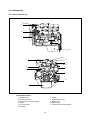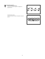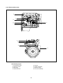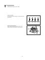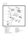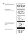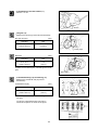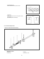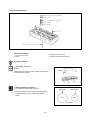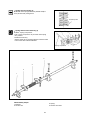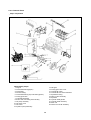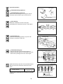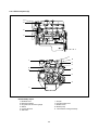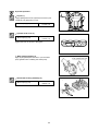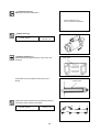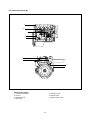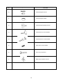
1
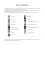
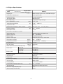
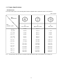
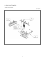
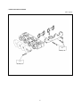
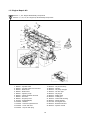
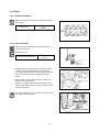
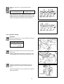
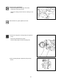
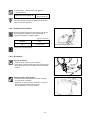
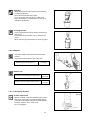
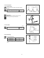
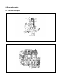
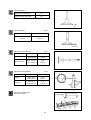
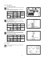
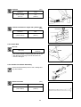
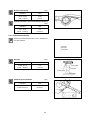
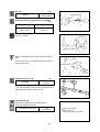
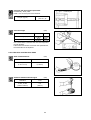
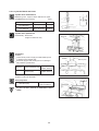
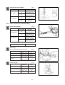
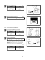
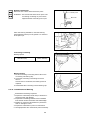
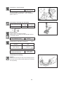
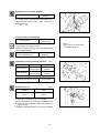
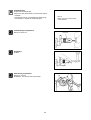
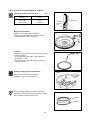
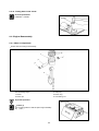
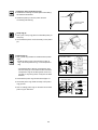
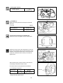
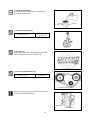
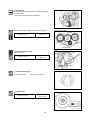
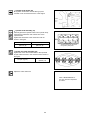
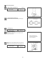
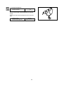
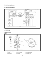
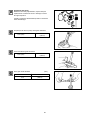
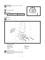
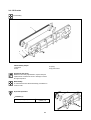
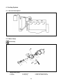
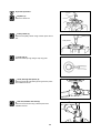
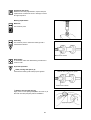
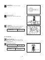
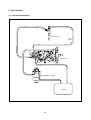
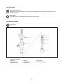
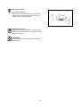
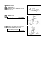
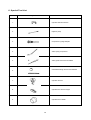
SB2013E02
May. 1 9 9 8
Service Manual
Diesel Engine
3.3 Liter (DB33A)
Important Safety Information
Most accidents involving product operation, maintenance and repair are caused by failure to observe basic safety
rules or precautions. An accident can often be avoided by recognizing potentially hazardous situations before an
accident occurs. A person must be alert to potential hazards. This person should also have the necessary training, skills and tools to perform these functions properly.
Read and understand all safety precautions and warnings before operating or performing lubrication,
maintenance and repair on this product.
Basic safety precautions are listed in the ÒSafetyÓ section of the Service or Technical Manual. Additional safety
precautions are listed in the ÒSafetyÓ section of the owner/operation/maintenance publication.
Specific safety warnings for all these publications are provided in the description of operations where hazards
exist. WARNING labels have also been put on the product to provide instructions and to identify specific hazards.
If these hazard warnings are not heeded, bodily injury or death could occur to you or other persons. Warnings in
this publication and on the product labels are identified by the following symbol.
WARNING
Improper operation, lubrication, maintenance or repair of this product can be dangerous and could result
in injury or death.
Do not operate or perform any lubrication, maintenance or repair on this product, until you have read
and understood the operation, lubrication, maintenance and repair information.
Operations that may cause product damage are identified by NOTICE labels on the product and in this publication.
DAEWOO cannot anticipate every possible circumstance that might involve a potential hazard. The warnings in
this publication and on the product are therefore not all inclusive. If a tool, procedure, work method or operating
technique not specifically recommended by DAEWOO is used, you must satisfy yourself that it is safe for you
and others. You should also ensure that the product will not be damaged or made unsafe by the operation, lubrication, maintenance or repair procedures you choose.
The information, specifications, and illustrations in this publication are on the basis of information available at the
time it was written. The specifications, torques, pressures, measurements, adjustments, illustrations, and other
items can change at any time. These changes can affect the service given to the product. Obtain the complete
and most current information before starting any job. DAEWOO dealers have the most current information available.
TO THE CUSTOMERS
This operation and maintenance manual is designed to serve as a reference for DHI's customers and distributors
who wish to gain basic product knowledge on DHI's DB33 Diesel engine.
To maintain the engine in optimum condition and retain maximum performance for a long time, CORRECT
OPERATION and PROPER MAINTENANCE are essential.
In this manual, the following symbols are used to indicate the type of service operations to be performed.
Removal
Adjustment
Installation
Cleaning
Disassembly
Pay close attention-Important
Reassembly
Tighten to specified torque
Align the marks
Use special tools of manufacturer's
Directional Indication
Lubricate with oil
Inspection
Lubricate with grease
Measurement
If you have any question or recommendation in connection with this manual, please do not hesitate to contact our
head office, dealers or authorized service shops.
CONTENTS
1. GENERAL INFORMATIONS
1.1. General Repair Instructions
1.2. Engine Specifications
1.3. Torque Specifications
1
1.4. Major Parts Fixing Bolts
1.5. Engine Repair Kit
1.6. Repair
2. ENGINE ASSEMBLY
2.1. General Description
2.2. Disassembly
19
2.3. Inspection and Repair
2.4. Reassembly
3. LUBRICATING SYSTEM
3.1. General Description
3.2. Oil Pump
61
3.3. Oil Filter
3.4. Oil Cooler
4. COOLING SYSTEM
4.1. General Description
4.2. Water Pump
66
4.3. Thermostat
5. FUEL SYSTEM
5.1. General Description
5.2. Fuel Filter
6. SPECIAL TOOL LIST
• WORLDWIDE NETWORK
70
5.3. Injection Nozzle
74
1. GENERAL INFORMATION
1.1. General Repair Instructions
1. For safety, park the truck on even ground or work station and fix the wheels using wedges and hand brake
during operation.
2. Before performing service operations, disconnect the grounding cable from the battery to reduce the chance
of cable damage and burning due to short-circuiting.
3. Before performing service operations release the air pressure in the machine air line system for safety. To not
do so is extremely dangerous.
4. Use covers to prevent the components from damage or pollution.
5. Brake oil and anti-freeze solution must be handled with reasonable care as they cause paint damage.
6. The use of proper tools and special tools where specified is important for efficient and reliable service
operation.
7. Use genuine DAEWOO parts exclusively.
8. Used cotter pins, gaskets, O-rings, oil seals, lock washers and self-lock nuts should be discarded and new
ones should be prepared for installation as normal function of the parts can not be maintained if these parts
are reused.
9. To facilitate proper and smooth reassembly operation, keep disassembled parts neatly in groups. Keeping
bolts and nuts separate is very important as they vary in hardness and design depending on the position of
installation.
10. Clean the parts before inspection or reassembly. Also clean oil ports, etc. using compressed air to make
certain they are free from restrictions.
11. Lubricate rotating and sliding faces of parts with oil or grease before installation.
12. When necessary, use a sealant on gaskets to prevent leakage.
13. Carefully observe all specifications for bolts and nuts torques.
14. When a service operation is completed, make a final check to ensure that the service has been done
properly.
1
1.2. Engine Specifications
Engine Model
Items
DB 33A
Engine type
Water-cooled, 4 cycle in-line, overhead valve type
Combustion chamber type
Direct injection type
Cylinder liner type
Dry type, casting liner
Timing gear system
Gear drive type
No. of piston ring
Compression ring 2, oil ring 1
No. of cylinder-bore¡¿stroke
(mm)
Total piston displacement
4-102¡¿100
(cc)
3,268
Compression ratio
(199 cu in)
17.5 : 1
Engine dimension(length¡¿width¡¿height)
Engine weight(dry)
(mm)
795¡¿701¡¿720
(kg)
340
(31¡¿28¡¿28 in)
(750 lbs)
Fuel injection order
1-3-4-2
Fuel injection timing(B.T.D.C static)
13¡˘
Type of fuel used
High-speed diesel fuel (SAE No.2)
Injection pump type
VE
Governor type
Mechanical governing
Injection nozzle type
(DOOWON)
Multi-hole type (6 hole) - VCO nozzle
Fuel injection pressure
(Kg/cm )
220
Compression pressure
(kg/cm )
30 (at 200 RPM)
Low idle speed
(R.P.M)
775-825
High idle speed
(R.P.M)
2400-2500
2
2
Intake and exhaust valve clearance(at cold)
Intake valve
Exhaust valve
(mm)
(3,128 psi)
(426 psi)
0.4
Open at
28 (B.T.D.C)
Close at
62 (A.B.D.C)
Open at
70 (B.B.D.C)
Close at
28 (A.T.D.C)
Lubrication method
Pressurized circulation
Oil pump type
Gear type
Oil filter type
Full-flow type
Lubricating oil capacity
(§⁄)
7.5 (Oil pan)
(1.97 gal)
Oil cooler type
Water cooled
Cooling method
Pressurized circulation
Cooling water capacity(engine only)
(§⁄)
7.5
(1.97 gal)
Thermostat type
Wax pallet type (with jiggle valve)
Generator voltage-capacity(V-A)
12-61
Starter Voltage-output(V-KW)
12-2.5
2
1.3. Torque Specifications
¡ Standards bolts
The torque values given in the following table should be applied where a particular torque is not specified.
(Unit : kgƒUm)
Bolt
identification
Bolt
diameter¡¿pitch
4T
Low carbon steel
7T
High carbon steel
6¡¿1.0
0.4-0.8
0.5-1.0
-
8¡¿1.25
0.8-1.8
1.2-2.3
1.7-3.1
10¡¿1.25
2.1-3.5
2.8-4.7
3.8-6.4
2.0-3.4
2.8-4.6
3.7-6.1
12¡¿1.25
5.0-7.5
6.2-9.3
7.7-11.6
¡ 12¡¿1.75
4.6-7.0
5.8-8.6
7.3-10.9
14¡¿1.5
7.8-11.7
9.5-14.2
11.6-17.4
¡ 14¡¿2.0
7.3-10.9
9.0-13.4
10.9-16.3
16¡¿1.5
10.6-16.0
13.8-20.8
16.3-24.5
¡ 16¡¿2.0
10.2-15.2
13.2-19.8
15.6-23.4
18¡¿1.5
15.4-23.0
19.9-29.9
23.4-35.2
20¡¿1.5
21.0-31.6
27.5-41.3
32.3-48.5
22¡¿1.5
25.6-42.2
37.0-55.5
43.3-64.9
24¡¿2.0
36.6-55.0
43.9-72.5
56.5-84.7
¡ 10¡¿1.5
9T
Alloy steel
The ¡ indicates that the bolts are used for female-threaded parts that are made of soft materials such as casting, etc.
3
1.4. Major Parts Fixing Bolts
¡ Cylinder head and block
(unit : kgƒUm)
2.5
2.1
18.0 lb¡⁄ft
15.2 lb¡⁄ft
72.32 lb¡⁄ft
10.0
11.5
83.17 lb¡⁄ft
5.3
38.33 lb¡⁄ft
4
¡ Intake and exhaust manifold
(unit : kgƒUm)
2.1
15.2 lb¡⁄ft
2.1
15.2 lb¡⁄ft
5
¡ Cylinder block and others
(unit : kgƒUm)
13.7
99.1 lb¡⁄ft
2.6
18.8 lb¡⁄ft
Lubricate with engine oil
2.1
15.2 lb¡⁄ft
7.9
57.0 lb¡⁄ft
2.6
18.8 lb¡⁄ft
2.4
Lubricate with engine oil
6
¡ Cylinder block and others
(unit : kgƒUm)
2.6
18.8 lb¡⁄ft
2.6
18.8 lb¡⁄ft
5.3
38.3 lb¡⁄ft
2.6
5.3
38.3 lb¡⁄ft
7
18.8 lb¡⁄ft
¡ Crankshaft and camshaft
(unit : kgƒUm)
44.0
318 lb¡⁄ft
9.75¡ 0.25
70.5 ¡ 1.8 lb¡⁄ft
12¡ 0.25
86.8 ¡ 1.8 lb¡⁄ft
16.0
115.7 lb¡⁄ft
5.5
39.8 lb¡⁄ft
2.5
18.1 lb¡⁄ft
16.0
115.7 lb¡⁄ft
8
¡ Thermostat and housing
(unit : kgƒUm)
2.1
10.5 lb¡⁄ft
5.3
25.1 lb¡⁄ft
9
1.5. Engine Repair Kit
Part No. 1¡›25 : Engine disassembly components
Part No. 1, 3, 21, 22, 25 : Engine top disassembly components
1. Gasket : Cylinder head
2. Gasket : Cylinder head cover and bolt
3. Gasket : Head cover
4. Gasket : Relief valve
5. Gasket : Injection pump
6. Gasket : Tappet chamber and bolt
7. Gasket : Oil cooler
8. Gasket : Oil pump cover
9. Oil seal : Crankshaft(RR)
10. Gasket : Retainer
11. Gasket : Case and cylinder block
12. Gasket : Cover and case
13. Gasket : Oil pan drain plug
14. Gasket : Oil pan and body
15. Gasket : Oil filter
16. Gasket : Oil pump and pipe
17. Gasket : Oil filter pipe
18. Gasket : Oil jet pipe
19. Gasket : Water pump
20. Gasket : Outlet pipe
21. Gasket : Thermostat housing
22. Gasket : Nozzle gasket
23. Oil seal : Crank gear case
24. Gasket : Exhaust manifold
25. Gasket : Injection nozzle
10
1.6. Repair
1.6.1. Cylinder Head Bolt
Tighten the cylinder head bolts in sequence as shown
in the figure.
Torque(kgƒUm)
11.5
( 83.2 lb¡⁄ft)
Front
1.6.2 Valve Clearance
Adjust the valve clearance in the following manner
using a feeler gauge.
Standard(in cold)
Intake and exhaust (mm)
0.4
(.016 in)
1. Bring the piston in either the No. 1 cylinder or the No.
4 cylinder to top dead center on the compression
stroke by turning the crankshaft until the TDC notched
line on the crankshaft pulley is aligned the timing
pointer.
2. Check to see if there is play in the No. 1 intake and
exhaust valve rocker arms.
If the No. 1 cylinder intake and exhaust valve rocker
arms are depressed, the No. 4 piston is at TDC on the
compression stroke.
TDC
The same results can be obtained by using the TDC
line on flywheel and pointer.
TDC line
11
Timing pointer
Adjust the clearances of valves marked with an
arrow
Rocker arm screw
lock nut torque (kgƒUm)
2.5
(18.1 lb¡⁄ft)
After adjusting the valve clearances referring to the
drawing, turn the crankshaft one full turn in the
rotative direction and align the TDC mark with the
pointer, then adjust the remaining valve clearances.
1.6.3. Injection Timing
Inspection
Check the notched line on the crankshaft pulley and
timing pointer are aligned.
Setting Timing (BTDC)
Engine : 13¡B̆TDC
I/P : Plunger Lift 0.3mm
(.0118 in)
TDC
Remove the inspection hole cover at the front of gear
case cover.
Check the alignment between the notched line on the
camshaft gear and the arrow mark of gear case cover.
Notched line
Arrow mark
Check the notched line on the injection pump is in
alignment with the notched line on the timing gear
cover.
Arrow mark
Check the alignment of the notched lines injection
pump and bracket.
Notched line
Notched line
12
Injection timing adjustment
1. Adjust fuel injection timing with crank pulley
notched line and timing pointer.
Adjust the timing pointer with the marking on the
pulley.
TDC
Disconnect the inj. pipes (4pieces) from I/P
2. Remove 2 fixing bolts of timing flange and injection
pump.
Remove bolt located at the center.
Insert the dial gauge to check the plunger lift.
3.Turn the timing flange to adjust the plunger lift to
0.3mm.
13
4. Install the No. 1 injection pipe and tighten to
specified torque.
Injection pipe nut torque (kgƒUm)
3¡›3.5
(21.7~25.3 lb¡⁄ft)
Do not overtighten the delivery valve holder. It will
distort the injection pump body shape and adversery
affect control rack operation.
1.6.4. Compression Pressure
Remove the glow plugs from all cylinders, then check
the compression pressure in each cylinder with a
compression gauge by engaging starter.
(kg/cm2, 200 rpm)
Standard
Limit
30
22¡›23
(312~327 psi)
Compression gauge adapter
Compression gauge adapter
1.6.5. Air Cleaner
Dry type air cleaner
¡ Observe the air cleaner service indicator
¡ Clean the air cleaner element and dust pan when the
RED band in the service indicator looks in the visible
position.
Air cleaner
service
indicator
Stop button
Cleaning primary filter element
Direct air inside of the element and blow out dusts
from the pleats completely.
(Maximum air pressure does not excess 2.1kg /cm2)
¡ Always replace the secondary element.
Do not attempt to reuse it by cleaning.
¡
14
Detergent
¡ Wash the element in warm water and nonsudsing
household detergent.
¡ Rinse the element with clean water
¡ Dry it thoroughly with natural air or electric fan.
Don't use a flame or compressed air for drying. It
damages the element.
Checking element
¡ Insert a light inside the clean and dry element and
examine it.
¡ Discard the element if tears, rips or damages are
found.
¡ Wrap and store good elements in a clean, dry place.
1.6.6. Radiator
Install the radiator cap tester and pressurize the
radiator.
¡ Inspect the cooling system if there any leak.
¡
Measuring pressure (kg/cm2)
1.0
(14.2 psi)
Radiator cap
Pressure valve opening pressure (kg/cm2)
0.87
(12.4 psi)
Vaccum valve opening pressure (kg/cm2)
0.05
(.71 psi)
1.6.7. Lubricating System
Oil filter replacement
¡ Before installing a new filter element apply a small
amount of clean engine oil to the element gasket.
¡ Install the new element. When the gasket contacts
the base, tighten it 3/4 of a turn more.
Do not overtighten.
15
Element
1.6.8. Fuel System
Injection nozzle
Check the spraying condition and injection starting
pressure.
Injection starting pressure (kg/cm2)
Correct
Incorrect
Incorrect
220
(3.128 psi)
Adjustment
Adjust the injection starting pressure with the
adjusting screw using a nozzle tester.
1.6.9. Fan Belt
Fan pulley
(mm)
Specified belt deflection
Depress here
10
(.393 in)
Generator pulley
Crank pulley
1.6.10. Glow Plug
Inspection(Resistance)
Silver color
4.5 §
Black color
1.6§
Check the continuity across the plug terminals and
body.
16
2. Engine Assembly
2.1. General Description
17
2.2. Disassembly
2.2.1. External Parts (A)
11
8
6
5
12
11
8
1
2
3
9
6
10
5
4
7
<Disassembly steps>
1. Breather hose
2. Exhaust manifold
3. Oil guide tube and level gauge
4. Starter
5. Cooling fan belt
6. Alternator
7. Oil pan
8. Cylinder head cover
9. Rubber hose
10. Water pump
11. Thermostat housing assembly
18
Important operations
¡ Exhaust manifold assembly(2)
Loosen the manifold fixing bolts in sequence of
figure's shown.
1
8
3
¡
5
6
4
7
2
Cylinder head cover(8)
Loosen the head cover bolts in sequence of figure's
shown
1
19
3
2
2.2.2. External Parts (B)
4
8
1
7
6
5
2
3
8
6
<Disassembly steps>
1. Fuel injection pipe
2. Injection nozzle
3. Glow plug
4. Intake manifold
5. Oil pipe
6. Oil filter assembly
7. Injection pump
8. Oil cooler assembly
20
Important operations
¡ Engine control cable.
Disassemble the engine control cable.
¡
Injection nozzle(2)
Avoid damaging the nozzle tips or other parts during
disassembly.
¡
Injection pump assembly(7)
When disassembving the injection pump, cap or
tape the delivery valve holder to avoid dirt entry.
21
2.2.3. Internal Parts
¡ Major Components
<Disassembly steps>
1. Rocker arm shaft assembly
2. Push rod
3. Cylinder head assembly
4. Cylinder head gasket
5. Fly wheel
6. Fly wheel housing
7. Rear oil seal assembly
8. Oil pump cover
9. Oil pump assembly
10. Piston and connecting-rod assembly
11. Crankshaft front nut and washer
12. Crankshaft pulley
13. Gear case cover
14. Idle gear
15. Camshaft assembly
16. Timing gear case
17. Crankshaft bearing cap and bearing
18. Thrust bearing
19. Crankshaft assembly
20. Crankshaft bearing
21. Tappet
22
Important operations
¡‹ Rocker
arm shaft assembly (1)
Loosen the rocker arm shaft assembly bolts a little
at a time in numerical sequence as shown in the
figure.
¡‹ Cylinder
head assembly (3)
Loosen the cylinder head bolts a little at a time in
the numerical sequence as shown in the figure.
Front
¡‹ Flywheel
(5)
Loosen the flywheel bolts a little at a time in
numerical sequence as shown in the figure.
Apply engine oil
¡‹ Piston
assembly (10)
Remove any carbon deposits from the upper part of
the cylinder bore using a scraper.
This will prevent damage to the piston and the
piston rings when they are removed from the
cylinder bore.
Position the piston to the top by turning the
crankshaft, remove the piston assembly from
cylinder using a wooden bar or hammer.
23
¡‹ Crankshaft
front nut and washer (11)
Wrench : 41 mm
Wrench
¡‹ Idle
gear (14)
Measure the following points before disassembly.
Idle gear end play.
(mm)
Standard
Limit
0.058¡›0.115
(.002~0.0045 in)
0.2
(.0078 in)
Feeler gauge
Backlash
(mm)
Standard
Limit
0.10¡›0.17
(.0039~.0069 in)
0.3
(.012 in)
Includes the crankshaft gear, camshaft gear and idle
gear.
Dial indicator
¡‹ Crankshaft
bearing cap and bearing (17)
Measure the crankshaft end play before
disassembly.
Crankshaft end play
Feeler gauge
(mm)
Standard
Limit
0.10¡›0.17
(.0039~.0067 in)
0.3
(.012 in)
Includes the crankshaft gear, camshaft gear and
idle gear.
Crankshaft
Loosen the crankshaft bearing cap bolts in
numerical sequence as shown in the figure.
Apply engine oil
24
¡‹ Thrust
bearing (18)
Remove the thrust bearing with steel wire.
Wire
¡‹ Tappet
(21)
Remove the tappets and mark the cylinder number
each tappet.
(Be careful against the damages)
Mark the cylinder No
Exhaust
2.2.4. General Components
¡ ‹ Rocker
arm, Bracket and shaft assembly
<Disassembly steps>
1. Bracket
2. Rocker arm
3. Spring
4. Rocker arm shaft
25
Intake
¡ Cylinder head assembly
<Disassembly steps>
1. Spring retainer and valve cotter
2. Spring and spring seat
3. Valve
4. Valve stem oil seal
Important operations
Mark the cylinder No. each component when it
disassembles.
¡ Valve spring
¡ Valve
¡ Valve seat
¡ Retainer and valve cotter (1)
Spring compressor
Valve spring compressor
26
¡ Piston and connecting-rod assembly
<Disassembly steps>
1. Piston ring
2. Snap ring
3. Piston pin and connecting-rod
4. Piston
Important operations
Mark the cylinder No. each component when it
disassembles.
¡
¡
¡
¡
27
Piston ring
Piston
Piston pin
Connecting-rod
¡‹Piston
ring (1)
Remove the piston rings
¡‹Snap
ring (2)
Remove the piston pin snap ring
¡‹ Piston
pin and connecting-rod (3)
Pull out the piston pin with brass bar
2.3. Inspection and Repair
Make the necessary adjustments, repairs and
replacements if excessive wear or damage is
discovered during inspection.
2.3.1. Cylinder Head
Lower face warpage
a straight edge and a feeler guage to measure
the four sides and the two diagonals of the cylinder
head lower face.
¡‹ Use
28
Lower face warpage and height
(mm)
Standard
Limit
Warpage
0.05 or less
(.002 in)
0.2
(.008 in)
Thickness
(reference)
89.95¡›90.05
(3.54~3.55 in)
89.75
(3.53 in)
2.3.2. Valve, Valve Guide and Valve Seat Insert
Valve contact width
(mm)
Standard
Limit
1.5
(.059 in)
2.0
(.079 in)
Contact width
Valve depression
(mm)
Standard
Limit
1.0
(.039 in)
2.5
(.098 in)
Depression
Valve seat angle
Valve seat angle
Valve seat insert replacement
Removal : Arc weld the entire inside circumference of
the valve seat insert.
¡ ‹ Cooling the valve insert for a few minutes
and pull out with a screw driver.
Installation : Use a bench press to smoothly press the
valve seat insert.
Valve seat
insert
Cylinder head
Welding bead
29
Valve seat angle
Intake valve seat angle
45¡˘
Exhaust valve seat angle
45¡˘
45¡˘
Valve seat angle
(mm)
Standard
Limit
1.5
(.059 in)
1.0
(.039 in)
Thickness
Valve stem outer diameter
(mm)
Standard
Standard
Intake valve
8.946¡›8.961
(.352~.353 in)
8.88
(.350 in)
Exhaust valve
8.921~8.936
(.351~.352 in)
8.88
(.350 in)
Valve stem outer diameter
¥†
¥–
¥
(mm)
Standard
Standard
Intake
0.04¡›0.07
(.002~.003 in)
0.2
(.008 in)
Exhaust
0.06~0.09
(.002~.009 in)
0.25
(.010 in)
Valve guide replacement
Remover, installer
Measuring
point
Remover, installer
30
2.3.3. Valve Spring
Valve Spring Free Length
Use a vernier caliper to measure the valve spring free
length.
If the measured value is less than the specified limit,
the valve spring must be replaced.
Standard
Exhaust and Intake
Valve Spring Free
Length
Free
length
Inner
Outer
49.0 mm
(1.93 in)
52.4 mm
(2.06 in)
53.6 mm
(2.11 in)
Limit
Remark
for
47.0 mm
(1.85 in) Industrial
50.0 mm
for
(1.97 in)
Automotive
50.6 mm
(1.99 in)
Valve Spring Inclenation
Use a surface plate and a square to measure the
valve spring inclination.
If the measured value exceeds the specified limit, the
valve spring must be replaced.
Valve spring
Inclination
Free
length
Inner
Outer
Standard
less than
1.3 mm
(.051 in)
-
Limit
Inclination
Remark
for
2.7 mm
(.106 in) Industrial
1.0 mm
for
(.039 in)
Automotive
1.0 mm
(.039 in)
Free
length
Square
Valve Spring Tension
Use a spring tester to measure the valve spring tension
if the measured value is less than the specified limit, the
valve spring must be replaced.
Standard
Valve Spring
14.5 kg
Tension at 40 mm
(32 lbs)
Set Length
10.9 kg
42mm
Inner
(1.65 in) (24 lbs)
23.0 kg
44mm
Outer
(1.73 in) (50.7 lbs)
Limit
Remark
11.5 kg
for
(25.4 lbs) Industrial
9.9 kg
for
(21.8 lbs)
Automotive
20.0 kg
(44.1 lbs)
Spring tester
2.3.4. Tappet
Inspect the tappets for excessive wear, damage and
any abnormalities.
Pitted
Crack
normal contact
Abnormal contact
31
Diameter
(mm)
Standard
Limit
27.97¡›27.98
(1.10 in)
0.2
(1.09 in)
Micrometer
Clearance between the tappet and cylinder body
(mm)
Standard
Limit
0.02¡›0.054
(.0008~.002 in)
0.1
(.004 in)
2.3.5. Push Rod
Run-out
Limit (mm)
0.03
(.0012 in)
¡‹ Use
a feeler gauge to measure the push rod run-out
the push rod along a smooth flat surface as
shown in the figure.
¡‹ Roll
2.3.6. Rocker Arm Shaft Assembly
Inspect all disassembled parts for wear, damage and
any abnormalities.
Rocker arm shaft
(mm)
Standard
Limit
18.98~19.00
(.747~.748 in)
18.85
(.742 in)
32
Dial indicator
Rocker arm bushing
(mm)
Standard
Limit
19.01~19.03
(.748¡›.749 in)
19.05
(.75 in)
Clearance between rocker arm shaft and bushing
(mm)
Standard
Limit
0.01¡›0.05
(.0004¡›.0020 in)
0.2
(.0079 in)
2.3.7. Camshaft Assembly
Inspect all disassembled parts for wear, damage and
any abnormalities.
¡‹
Camshaft
Cam gear
¡‹ Thrust plate
¡‹
End play
(mm)
Standard
Limit
0.050¡›0.114
(.0020¡›.0045 in)
0.2
(.0079 in)
Camshaft gear
Thrust plate
Camshaft
Feeler gauge
Camshaft journal diameter
(mm)
Standard
Limit
55.94¡›55.97
(2.202~2.204 in)
55.60
(2.189 in)
33
Run-out
(mm)
Standard
56.00¡›56.03
(2.205~2.206 in)
Camshaft bearing
Clearance between camshaft journal and body
(mm)
Standard
Limit
0.03¡›0.09
(.001~.004 in)
0.15
(.006 in)
Camshaft bearing replacement
Remover, installer
Remover, installer
Align the camshaft oil holes with the cylinder body oil
ports.
The oil holes of No. 1 camshaft bearing(front side are
two otherwise is one.
Camshaft run-out (T.I.R)
Standard
Align the oil ports
(mm)
0.1
(.004 in)
¡‹ Place
the camshaft on a measuring stand.
a dial indicator to measure the camshaft run-out
¡‹ Note the total indicator reading (T.I.R).
¡‹ Use
Camshaft bearing
Replace the camshaft gear if any damages or
excessive backlash are found.
Gear bolt torque (kgƒUm)
14.0
(101.3 lb¡⁄ft)
34
¡ÿRefer to the standard
backlash table at
"Major components disassembly"
Cam gear and thrust plate replacement
Disassembly : Gear puller
Install : Use a bench press and a hammer
16.0
(115.7 lb¡⁄ft)
Torque (kgƒUm)
Cam lobe height
Cam lobe height (C)
Cam journal diameter (A,B)
Camshaft gear
(mm)
Standard
Limit
47.7
(1.88 in)
56.0
(2.20 in)
46.5
(1.83 in)
55.6
(2.19 in)
Use a micrometer to measure the cam lobe height and
journal diameter.
If the measured number is less than the specified limit,
the camshaft must be replaced.
2.3.8. Idle Gear and Idle Gear Shaft
Shaft outside diameter
(mm)
Standard
Limit
44.94¡›44.97
(1.76~1.77 in)
44.84
(1.765 in)
use a micro.
Clearance between shaft and gear
(mm)
Standard
Limit
0.009¡›0.060
(.0004~.0023 in)
0.2
(.008 in)
35
2.3.9. Cylinder Block and Liner
For steel liner
For cast liner
Standard
105.00¡›105.04
(4.13~4.14 in)
105.99¡›106.01
(4.17~4.179 in)
Limit
105.10
(4.14 in)
106.10
(4.18 in)
Cylinder liner replacement
Disassembly : Removeer
Angle for steel liner only
Angle
Remover
Installation
Installer
¡‹ Use a bench press to apply an initial seating force
of 500kg to the cylinder liner.
¡‹ And then apply a final seating force of 2,500kg to
fully seat the cylinder liner.
Steel liner
Tight fit (standard) (mm)
Cast liner
Loose fit (mm)
20mm
Cylinder bore measurement
Measuring point : Approx. 20mm bellow from upper
face(Maximum wear portion)
(mm)
Installer
Bench press
0.001¡›0.019
(.0004~.0007 in)
0.005¡›0.026
(.0002~.0010 in)
After installing the liner measure the cylinder liner
projection and inner diameter.
Square Liner projection
Liner projection
Standard (mm)
0.03¡›0.010
(.0011~.0004 in)
¡‹ For
the cast liner, removal or installation is done
easily.
Feeler gauge
36
Cylinder liner inner diameter
(mm)
102.021¡›102.040
(4.016~4.017 in)
102.041¡›102.060
(4.017~4.018 in)
102.021¡›102.030
(4.016~4.017 in)
102.031¡›102.042
(4.017 in)
A
For steel liner
Standard
C
A
For cast liner
B
2.3.10. Piston, Piston Pin and Piston Ring
Piston outer diameter
(mm)
Piston grade
For steel liner
Standard
101.955¡›101.975
(4.014~4.015 in)
101.975¡›101.994
(4.015~4.016 in)
101.953¡›101.967
(4.014~4.015 in)
101.963¡›101.977
(4.014~4.015 in)
A
C
A
For cast liner
B
Piston and liner bore clearance
Standard (mm)
0.055~ 0.075
Piston ring
Piston ring and ring groove clearance
1st compression ring
2nd compression ring
Oil ring
Standard
Limit
0.085¡›0.11
(.003~.009 in)
0.035¡›0.055
(.001~.002 in)
0.03¡›0.07
(.001~.003 in)
0.2
(.008 in)
0.15
(.006 in)
0.15
(.006 in)
Piston ring gap
1st compression ring
2nd compression ring
Oil ring
(mm)
(mm)
Standard
Limit
0.25¡›0.45
(.010~.018 in)
0.2¡›0.4
(.008~.016 in)
0.2¡›0.4
(.008~.016 in)
1.5
(.006 in)
1.5
(.006 in)
1.5
(.006 in)
37
20mm
Liner Grade
Piston pin outside diameter
(mm)
Standard
Limit
35.000¡›35.005
(1.377~1.378 in)
34.95
(1.376 in)
Piston pin and piston clearance
(mm)
0.005
(.0002 in)
Limit (mm)
2.3.11. Connecting Rod and Bearing
Connecting rod aligmment (parallelism)
Alignment (per length of 100mm (3.94 in))
Standard
Limit
0.05
(.002 in)
0.2
(.009 in)
(mm)
Bushing inside diameter
Standard
35.017~35.025
(1.379 ~1.380 in)
Use a caliper calibrator and micrometer to measure
the piston pin and connecting rod small end bushing
clearance.
Piston pin and connecting rod small end bushing
(mm)
Standard
Limit
0.01~0.03
(.0004~.0012 in)
0.05
(.002 in)
38
Bushing replacement
Removal : Use a brass bar and a bench press
Bench press
Installation : Use a brass bar and a bench press. The
connecting rod busing oil port must be
aligned with the connecting rod oil port.
After new bushing installation, ream the bushing
inside diameter with a pin hole grinder or a reamer to
fit the piston pin.
Brass bar
Pin hole grinder
Reamer
Connecting rod bearing
Bearing spread
Standard (mm)
68.00¡›68.01
(2.677~2.678 in)
Bearing tension
1. Fit the connecting rod bearing lower half into the
connecting rod bearing cap.
2. Check the connecting rod bearing lower half
tension.
If the tension is insufficient, the bearing must be
replaced.
3. Reassemble the connecting rod and bearing cap.
2.3.12. Crankshaft and Bearing
¡‹ Crankshaft
and bearing inspection
1. Inspect the crankshaft journal and pin surfaces for
excessive wear and damage.
2. Inspect the oil seal fitting surfaces of the crankshaft
front and rear ends for excessive wear and damage.
3. Replace or repair the crankshaft if any excessive
wear or damage is found.
4. Inspect the crankshaft oil ports for obstructions.
5. Use high pressure air to clean the oil ports if necessary.
39
Crankshaft pin outside diameter
¤
63.932¡›63.944
(2.517~2.517 in)
Standard (mm)
Use a micrometer to measure the crankshaft pin
outside diameter across points ¤ and ¤Łat the two
points ¤Øand ¤Œ.
Connecting rod bearing cap reassembly
Connecting rod bolt torque (kgƒUm)
Bolt type
A:
11
B:
TY
11T
12¡ 0.25
9.75¡ 0.25
(86.7 ¡ 1.81 lb¡⁄ft) (70.51 ¡ 1.81 lb¡⁄ft)
A
B
Bolt head
or
TY
12T
Inside diameter
- Apply engine oil to bearing surface.
- Measure the connecting rod inside diameter with an
inside dial indicator.
Connecting rod bearing
nominal diameter (mm)
64§j
(2.52 in)
Crankshaft pin and bearing clearance
Standard
Limit
0.03¡›0.07
(.001~.003 in)
0.10
(.004 in)
Under size
Bearing specifications
(mm)
(mm)
0.25¡›0.50
(.010~.020 in)
Crankshaft journal bearing
Tension
Fit the journal bearing into the journal bearing cap and
check the tension with the same method of connecting
rod cap bearing.
40
¤Ł
¤Ø¤Œ
¤Ł
¤
¤Ø
¤Œ
Crankshaft journal outside diameter
B
Use a micrometer to measure the crankshaft journal
outside diameter across points £ and £ at the two
points ¥ and ¥–.
I II
B
75.913¡›75.925
(2.989 in.)
Standard (mm)
B
A
Journal bearing cap reassembly
24
(173.6 lb¡⁄ft)
Torque (kgƒUm)
Inside diameter
-Apply engine oil to bearing surface.
-Measure the journal bearing cap inside diameter with
an inside dial indicator.
Journal bearing
nominal diameter (mm)
76§j
(2.992 in)
Crankshaft journal and bearing clearance
(mm)
Standard
Limit
Center bearing
0.065¡›0.116
(.003~.006 in)
0.15
(.006 in)
Other bearings
0.025~0.076
(.001~.003 in)
0.11
(.004 in)
Under size
Bearing specifications (mm)
0.25~0.50
(.010~.020 in)
Crankshaft run-out
(mm)
Standard
Limit
0.05
(.002 in)
0.40
(.016 in)
1. Mount the crankshaft on a set of v-blocks.
2. Set a dial indicator to the center of the crankshaft journal
3. Gently turn the crankshaft in the normal direction of
engine rotation.
4. Read the dial indicator(TIR) as you turn the crankshaft.
41
Refer to
"Major components disassembly"
- Crankshaft bearing cap.
Crankshaft gear
Inspect the crankshaft gear
- Before the gear disassembly, check the crank gear
backlash.
- If excessive wear of any damage is found through
the inspection, replace the crankshaft gear.
Crankshaft gear replacement
Removal : Remover
Refer to
"Major components disassembly"
- Gear backlash.
Remover
Installation
Installer
Installer
Pilot bearing replacement
Removal : remover
Installation : Use a brass bar and hammer.
42
2.3.13. Flywheel and Housing(Rear Oil Seal)
¡ ‹Flywheel thickness (Friction face)
(mm)
Standard
Limit
33.4¡›33.6
(1.315~1.323 in)
32.5
(1.280 in)
Friction face
Crankshaft
assembly
face
Ring gear replacement
Removal : Use a brass bar and hammer
- Strike around the edges of the ring gear with a
hammer and brass bar to remove it.
Installation :
-Heat the ring gear evenly with a gas burner to invite
thermal expansion.
Do not allow the temperature of the ring gear to
exceed 200¡ (390¢ )
-Use a hammer to install the ring gear when it is
sufficiently heated.
Flywheel housing oil seal replacement
Installer
Removal : Use a pry bar and hammer.
Installation : Use a oil seal installer.
If the crankshaft contact area wears excessively,
move the contact area with a oil seal spacer. Install
new oil seal and discard the used one.
Oil seal
Spacer
43
2.3.14. Timing Gear Case Cover
Oil seal replacement
Installation : Installer
Installer
2.4. Engine Reassembly
2.4.1. Minor Components
¡ ‹Piston and connecting-rod assembly
4
1
3
2
3
5
<Disassembly steps>
1. Piston
2. Piston pin
3. Snap ring
4. Piston ring
5. Connecting rod
Important operation
Piston heater
¡ ‹ Piston (1)
Use a piston heater to heat the piston approximately
60¡ (140¢ )
44
¡ ‹ Piston pin and connecting-rod (2)
1. Install the connecting-rod to the piston with setting
the marks as illustrated.
Piston head
Front mark
2. Install the piston pin into the piston and the
connecting-rod bushing
Cylinder numder
marked side
¡ ‹ Snap ring (3)
1. Use a pair of snap ring pliers to install the piston pin
snap ring.
2. Check that the piston moves smoothly on the piston
pin.
¡ ‹Piston ring (4)
1. Use a piston ring installer to install the three piston
rings.
- Install the piston rings in the following order: oil
ring ¤M2nd compression ring ¤M1st compression
ring.
FOR STEEL LINER
1st ring
2nd ring
¡ The marked side of the two compression rings
must be facing up. The undercut side of the 2nd
compression ring will be facing down. As the oil
ring has no any facing mark, it may face in either
direction.
2. Lubricate the piston ring surfaces with engine oil.
3. Check the piston ring rotate smoothly in the piston
ring grooves.
Marked side
Oil ring
FOR CAST LINER
1st ring
2nd ring
4. Use Cr-coating piston ring for cast liner and normal
piston ring for steel liner.
Oil ring
45
¡ ‹ Cylinder head assembly
4
3
1
2
<Disassembly steps>
1. Valve stem oil seal
2. Valve
3. Spring seat and spring
4. Spring retainer and cotter key
Important operation
¡ ‹ Valve stem oil seal (1)
Installer
Lubricate the oil seals and valve guides and install the
oil seals with an installer.
¡ ‹ Intake and exhaust valves (2)
1. Lubricate valve stems with engine oil.
Installer
Intake valve
Exhaust valve
Big
Small
2. Install the valves to the intake and exhaust guides.
Install the valves to their original lapped valve
seats.
(Valve face)
46
¡ ‹ Spring seat and spring (3)
Install the valve springs with their painted end(the
close pitched end) facing down.
Painted portion
¡ ‹ Spring retainer and cotter key (4)
Installer : Spring compressor
- Use a spring compressor to push the valve spring
into position.
- Install the cotter key
- Set the cotter key by tapping lightly around the head
of the collar with a rubber hammer.
Spring compressor
4
3
2
1
<Disassembly steps>
1. Bracket
2. Rocker arm
3. Spring
4. Rocker arm shaft
47
2.4.2. Internal Parts
¡ ‹ Major components
11
12
<Disassembly steps>
1. Tappet
2. Crankshaft bearing(upper)
3. Crankshaft
4. Thrust bearing
5. Crankshaft bearing cap and bearing(lower)
6. Timing gear case
7. Camshaft assembly
8. Piston and connecting rod assembly
9. Oil pump assembly
10. Oil pump cover
11. Oil cooler
12. Injection pump assembly
13. Idle gear
14. Timing gear case cover
15. Crankshaft pulley
16. Crankshaft front nut and washer
17. Flywheel housing
18. Rear oil seal assembly
19. Flywheel
20. Cylinder head gasket
21. Cylinder head assembly
22. Push rod
23. Rocker arm shaft assembly
48
Important operation
With oil hole
and groove
Fit correctly
¡ ‹ Crankshaft bearing (upper) (2)
¡ ‹Crankshaft bearing (lower) (5)
Center lower half bearing has no oil groove and oil
hole while others all have oil groove and oil hole.
No oil groove and hole
(center lower)
¡ ‹Crank shaft (3)
Install the crankshaft so that the crank gear
assembled part is directed to the front of the engine.
Front
¡ ‹ Thrust bearing (4)
Oil groove side
Install the thrust bearings with the oil groove side
facing the crankshaft contact face.
¡ ‹ Crankshaft bearing cap
- Lubricate the bearing cap bolts with engine oil
- Install the bearing caps to the crankshaft. The arrow
mark must be pointing to the front of the engine.
Arrow mark(position No. punched)
Front
Tighten the bearing cap bolts to the specified torque a
little at a time in the numerical order shown in the
figure.
Torque (kgƒUm)
Arrow mark
24
(173.6 lb¡⁄ft)
Check that the crankshaft turns smoothly by manually
rotating it.
Lubricate with enging oil
49
¡ ‹ Timing gear case (6)
2.6
(18.8 lb¡⁄ft)
Torque (kgƒUm)
¡ ‹ Camshaft (7)
Tighten the thrust plate bolts through the camshaft
gear hole.
¡ ‹Torque
(kgƒUm)
2.1
(15.2 lb¡⁄ft)
16
(115.7 lb¡⁄ft)
Thrust plate bolt
Camshaft gear bolt
Camshaft gear
¡ ‹Piston and connecting rod assembly (8)
2nd compression ring
Position the piston ring gaps as shown in the figure.
Oil ring
Position the piston front mark towards the front of the
engine. Use a hammer grip to push the piston in until
it makes contact with the crank pin. At the same time,
rotate the crankshaft until the crank pin reaches its
highest point.
Set the bearing cap cylinder number marks and the
connecting-rod cylinder number marks.
The marks must be facing the exhaust manifold.
¡ ‹ Connecting rod cap bolt
Bolt head
11
TY
11T
TY
12T
Cylinder No.
12¡ 0.25
9.75¡ 0.25
(70.5 ¡ 1.8 lb¡⁄ft)
(86.8 ¡ 1.8 lb¡⁄ft)
-Lubricate the connecting-rod cap bolt threads and
setting faces with MoS grease.
Torque (kgƒUm)
50
Top ring
¡ ‹ Oil pump assembly(9)
Full up the oil pump with engine oil and install the
pump to the cylinder body.
Oil
Oil pump
¡ ‹ Oil pump mounting bolts
Torque (kgƒUm)
3.8
(27.5 lb¡⁄ft)
¡ ‹ Oil cooler(11)
Tighten the cooler bolts to the specified torque. Start
from the middle and work out to either side.
¡ ‹Injection pump assembly (12)
Torque (kgƒUm)
2.6
(18.8 lb¡⁄ft)
"ƒU" ; Injection pump fixing bolts
Check the punched line of the injection pump body is
aligned to the pump bracket line.
Arrow mark
Notched line
Notched line
51
¡ ‹ Idle gear(13)
Use the thrust collar fixing bolt as a guide to install the
idler gear shaft.
The oil port must be facing the camshaft.
Set the timing marks (A,B,C) as shown in the figure.
Injection pump gear
Idle gaer
Idle gear bolt
Torque (kgƒUm)
"B" mark
2.6
(18.8 lb¡⁄ft)
"C" mark
Crankshaft
gear
"A" mark
Camshaft gear
¡ ‹ Crankshaft front nut (16)
Pulley
Wrench : 41 mm
2.6
(18.8 lb¡⁄ft)
Torque (kgƒUm)
Wrench
¡ ‹ Flywheel housing (17)
Fixing bolts torque
14kgƒUm (101.25 lb¡⁄ft)
¡ ‹ Flywheel (19)
Torque (kgƒUm)
16.0
(115.7 lb¡⁄ft)
Lubricate with engine oil
52
¡ ‹ Cylinder head gasket (20)
The gasket "TOP" mark must be facing up and
"FRONT" mark is towards the front of the engine.
Front top mark
Front
¡ ‹ Cylinder head assembly (21)
Carefully place the cylinder head on the cylinder body.
Lubricate the head bolts and contact face of the
cylinder head.
Tighten the head bolts in the numerical order as
shown in the figure.
1st step
7.0
(50.6 lb¡⁄ft)
2nd step
11.5
(83.2 lb¡⁄ft)
Front
¡ Shorter head bolts are used
for injection pump side
¡ ‹ Rocker arm shaft assembly (23)
Tighten the rocker arm bracket bolts to the specified
torque a little at a time in the numerical order shown in
the figure.
Torque (kgƒUm)
3.1
(22.4 lb¡⁄ft)
Adjust the valve clearance
Refer to MAINTENANCE for
the valve clearance adjustment
procedure.
53
2.4.3. External parts (A)
11
8
6
5
7
11
8
1
2
3
9
6
10
5
4
7
<Disassembly steps>
1. Breather hose
2. Exhaust manifold
3. Oil guide tube and level gauge
4. Starter
5. Cooling fan belt
6. Alternator
7. Oil pan
8. Cylinder head cover
9. Rubber hose
10. Water pump
11. Thermostat housing assembly
54
Important operation
¡ ‹ Oil pan (1)
- Apply liquid gasket to the cylinder block and oil pan.
- Install oil pan gasket and oil pan.
Bolt torque (kgƒUm)
1.6
(11.6 lb¡⁄ft)
¡ ‹ Cylinder head cover (2)
Bolt torque (kgƒUm)
2.1
(15.2 lb¡⁄ft)
Tighten the bolts as shown in the figure.
1
¡ ‹ Water pump assembly (3)
Apply liquid gasket(belco bond No. 4) to the water
pump gasket before installing the water pump.
¡ ‹Thermostat housing assembly (5)
Bolt torque (kgƒUm)
5.3
(38.3 lb¡⁄ft)
55
3
2
Apply liquid gasket
to the cylinder block side
¡ ‹ Cooling fan belt (13)
Adjust the cooling fan belt tension.
Refer to Maintenance for
the fan bolt tension adjustment
¡ ‹Starter motor (9)
Torque (kgƒUm)
8.6
(62.2 lb¡⁄ft)
¡ ‹Exhaust manifold (11)
"TOP" mark
Carefully install the gasket with the "TOP" mark side
facing up.
Install either end of the distance tube in the spot
facing.
Distance tube
Tighten the exhaust manifold and gasket fixing bolts in
numerical order as shown in the figure.
Torque (kgƒUm)
2.6
(18.8 lb¡⁄ft)
1
3
56
8
5
6
7
4
2
2.4.4. Extermal Parts (B)
3
6
7
1
2
5
3
4
6
2
1
<Disassembly steps>
1. Oil filter and bracket
2. Oil pipe
3. Intake manifold
4. Glow plug
5. Injection nozzle
6. Injection pipe
7. Engine control lever
57
Important operation
¡ ‹Main oil filter and bracket (1)
'A' bolt torque
(kgƒUm)
5.3
(38.3 lb¡⁄ft)
¡ ‹Intake manifold assembly (3)
Install the gasket with its protruding part facing up.
Protruding Part
¡ ‹ Glow plug (4)
Torque (kgƒUm)
5.3
(38.3 lb¡⁄ft)
¡ ‹ Injection nozzle (5)
Adjusting the opening pressure with adjust screw
using a nozzle tester.
Refer to maintenance for
the injection nozzle opening
pressure adjustment
Replace the nozzle gasket and dust cover with new
one.
Tighten the injection pipe sleeve nut and flange nut.
Torque (kgƒUm)
Dust cover
2.6
(18.8 lb¡⁄ft)
Nozzle gasket
58
¡ ‹ Fuel injection pipe (6)
Torque (kgƒUm)
3.0
(21.7 lb¡⁄ft)
Delivery valve holder must be tightened as specified
torque.
Excessive torque causes leakage at control rack and
pipe.
Delivery valve
Holder torque (kgƒUm)
4.0~4.5
(28.9~32.5 lb¡⁄ft)
59
3. Lubricating System
3.1. General Description
O/P : Opening pressure
O/P warning
lamp
Full flow filter
By-pass
valve
Start
S/W
Battery
Oil filter
warning lamp
O/P 1kg/cm2
By-pass
valve
Oil press S/W
Cylinder body main oil gallery
Paper
filter
O/P 8kg/cm2
Oil
cooler
O/P 2kg/cm2
Oil relief
valve
Oil
relief
valve
Oil pump
Crank
shaft
brgs.
Cam
shaft
brgs.
Con.
rod
brgs.
Cyl.
head
valve
system
Timing
idle
gear
Oil strainer
Oil pan
3.2. Oil Pump
Disassembly
1
5
4
3
6
2
<Disassembly steps>
1. Strainer
2. Suction pipe
3. Cover and dowel
4. Drive gear
60
5. Drive shaft and gear
6. Driven gear shaft
Injection
pump
Inspection and repair
Make the necessary adjustments, repairs and part
replacements if excessive wear or damage is found
through inspection.
Visually inspect the disassembled parts for excessive
wear and damage.
Oil pump cover and oil pump drive gear clearance.
Limit (mm)
0.18
(.007 in)
Cover and driven gear clearance
Limit (mm)
0.12
(.005 in)
Drive gear shaft diameter
(mm)
Standard
Limit
16.0
15.9
(.626 in)
61
Reassembly
To Assemble, follow the disassembly procedures in
reverse order.
Important operation
¡ ‹Strainer (1)
Torque (kgƒUm)
1.0¡›1.8
(7.233~13.0 lb¡⁄ft)
3.3. Oil Filter
Disassembly
<Disassembly steps>
1. Oil filter ass'y
2. Head-oil filter
3. Element-oil fiter
4. Relief valve ass'y
5. Gasket
6. Bolt
7. Spring washer
8. Plain washer
9. O-Ring
10. Plug-screw
Inspection and repair
Make the necessary adjustments, repairs and part
replacements if excessive wear or damage is found
through inspection.
62
Reassembly
To reassemble follow the disassembly procedures in
reverse order.
Important operation
¡ ‹ Relief Valve (1)
Torque (kgƒUm)
2.5
(18.1 lb¡⁄ft)
63
3.4. Oil Cooler
Disassembly
1
4
3
2
<Disassembly steps>
1. Element
2. Bolt
3. Spring
4. By-pass valve
Inspection and repair
Make the necessary adjustments, repairs and part
replacements if excessive wear or damage is found
through inspection.
Reassembly
To reassemble follow the disassembly procedures in
reverse order.
Important operation
¡ ‹ Element (1)
Torque (kgƒUm)
2.6
(18.8 lb¡⁄ft)
64
4. Cooling System
4.1. General Description
4.2. Water Pump
Disassembly
<Disassembly steps>
1. Cover
2. Impeller
3. Center-Fan
4. Snap ring
5. Shaft bearing and spacer
6. Seal unit, washer and seal
65
Important operation
¡ ‹Impeller (2)
Removal : Remover
¡ ‹Pulley center (3)
Remove the pulley center using a bench press and a
bar.
Bench press
Pully center
¡ ‹ Snap ring (4)
Remove the snap ring using a snap ring plier.
¡ ‹ Shaft, bearing and spacer (5)
Remove the shaft and bearings using a bench press
and suitable remover.
¡ ‹ Seal unit, Washer and seal (6)
Remove the seal unit using a bench press and
suitable remover.
66
Inspection and repair
Make the necessary adjustments, repairs and part
replacements if excessive wear or damage is found
through inspection.
Bearing replacement
Removal ;
Use a bench press
Assembly
Use a bench press to install two bearings with a
marked side outward.
Marked side outward
Reassembly
To assemble, follow the disassembly procedures in
reverse order.
Important operation
¡ ‹Shaft, bearing and spacer (5)
Lubricate the bearing with multi-purpose grease.
Lubricate with multi purpose grease
Marked side outward
¡ ‹ Washer, seal and seal unit (6)
Apply a thin coat of liquid gasket(Belco bond No. 4) to
the seal unit outer periphery before installation.
Apply liquid gasket
67
¡ ‹ Snap ring (4)
Install the snap ring using a snap ring plier.
¡ ‹ Pulley center (5)
Install the pulley center using a bench press.
¡ ‹ Impeller (2)
ƒUInstall the impeller to the shaft using a bench press.
ƒUUse a feeler gauge to measure the clearance
between the impeller and the pump body.
Bench press
0.3¡›0.8
(.012~.031 lb¡⁄ft)
Standard (mm)
Feeler gauge
4.3. Thermostat
Inspection and repair
Make the necessary adjustments, pepairs and part
replacements if excessive wear or damage is found
through inspection.
Valve opening temperature
Agitating rod
Thermometer
80¡›84
(176¢ ~183¢ )
Standard (¡ )
Valve lift(at testing temperature)
Standard
approx. 10 mm (at 95¡ )
(.393 in (at 203¢ ) )
68
Wood piece
5. Fuel System
5.1. General Description
Injection nozzle
Fuel
return
Injection pump
Fuel filter & water separator
Fuel tank
69
5.2. Fuel Filter
Inspection and repair
Make the necessary adjustments, repairs and part replacements if excessive wear or damage is found
through inspection.
Reassembly
To assemble, follow the disassembly procedures in reverse order.
5.3. Injection Nozzle
Disassembly
<Disassembly steps>
1. Plunger
2. Retaining nut
3. Injection nozzle
4. Spacer
5. Spring seat
6. Nozzle spring
7. Adjust shim
8. Nozzle holder body
70
Important operation
¡ ‹Injection nozzle (3)
Remove the nozzle assembly from the nozzle body.
Keep the parts separately to maintain the proper
needle valve to body combination.
Inspection and repair
Make the necessary adjustments, repairs and part
replacements if excessive wear or damage is found
through inspection.
Reassembly
To assemble, follow the disassembly procedures in
reverse order.
71
Important operation
¡ ‹Injection nozzle (3)
Align the nozzle dowel pin with the dowel hole in the
nozzle holder body.
¡ ‹Retaining nut (2)
Torque (kgƒUm)
6~8
( 43.4~57.9 lb¡⁄ft)
¡ ‹Adjust shim (7)
The injection nozzle injection starting pressure can be
adjusted after the adjusting shim is installed.
Injection starting pressure (kg/cm2)
220
( 3.128 psi)
72
6. Special Tool List
No.
Figure
Tool name
1.
Cylinder head bolt wrench
2.
Injection pump
3.
Compression gauge adapter
4.
Valve spring compressor
5.
Valve guide remover and installer
Camshaft bearing remover and installer
6.
7.
Cylinder remover
8.
Cylinder liner remover angle
9.
Cylinder liner installer
73
No.
Figure
Tool name
10.
Crankshaft gear remover
11.
Crankshaft gear installer
12.
Crankshaft pilot bearing remover
13.
Crankshaft rear oil seal installer
14.
Crankshaft front oil seal installer
Valve stem oil seal installer
15.
16.
Piston ring compressor
17.
Water pump impeller remover
74