1
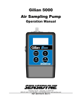
LASER DUST
MONITOR
LASER DUST MONITOR
➨
0.1
5
1
2
0
10
mg/M 3
10 MIN
MANUAL
MODEL LD-1
POWER
BATT.
O-ADJ
X 10
START
/STOP
OPERATION & SERVICE MANUAL
for the following Laser Dust Monitor models:
7012201-1 (LD-1)
7012201-2 (LD-1H)
WARNING
Class I laser product with embedded Class IIIb
invisible laser diode (781 nanometers, 3 milliwatts) inside internal laser optics housing. Internal access by authorized personnel only. This
product complies with 21 CFR 1040.10 and 1040.11.
16333 Bay Vista Dr. • Clearwater, Florida 33760 • (800) 451-9444 • (727) 530-3602 • (727) 539-0550 [FAX]
Revision C • October 1996 (Document No. 7012201-1M)
PACKING LIST
LASER DUST MONITOR
The items listed below are shipped with the Sensidyne Laser Dust Monitor:
•
Laser Dust Monitor (either Model LD-1 or LD-1H)
•
Cleaning brush
•
Operation & Service Manual
ALWAYS check to make certain
you have received all of the items listed above.
If you have any questions or need assistance,
contact your Sensidyne Sales Representative, or call
800-451-9444
or
727-530-3602
SENSIDYNE® 7012201-1M (Rev C) 10/96
3
LASER DUST MONITOR
PROPRIETARY NOTICE
This manual was prepared by Sensidyne, Inc. exclusively for the owner of the Sensidyne Laser Dust Monitor. The material within this manual is the proprietary information of Sensidyne, Inc. and is to be used only to understand, operate, and
service the instrument. By receiving this document, the recipient agrees that neither this document nor the information disclosed within nor any part thereof shall be reproduced or transferred, physically, electronically or in any other form, or
used or disclosed to others for manufacturing or for any other purpose except as specifically authorized in writing by
Sensidyne, Inc.
COPYRIGHT NOTICE
© 1996 Sensidyne, Inc. ALL RIGHTS RESERVED. Information contained in this document is protected by copyright. No part
of this document may be photocopied, reproduced, or translated to another program or system without prior written
authorization from Sensidyne, Inc.
TRADEMARK NOTICE
Sensidyne and the Sensidyne logo are registered trademarks of Sensidyne, Inc. The trademarks and service marks of
Sensidyne, Inc. are protected through use and registration in the United States.
DISCLAIMER
SENSIDYNE, INC. ASSUMES NO RESPONSIBILITY WHATSOEVER, TO ANY PARTY WHOSOEVER, FOR
ANY PROPERTY DAMAGE, PERSONAL INJURY, OR DEATH RECEIVED BY OR RESULTING FROM, IN
WHOLE, OR IN PART, THE IMPROPER USE, INSTALLATION, OR STORAGE OF THIS PRODUCT BY THE
USER, PERSON, FIRM, ENTITY, CORPORATION OR PARTY NOT ADHERING TO THE INSTRUCTIONS
AND WARNINGS IN THIS MANUAL, OR OTHERWISE PROVIDED BY THE SELLER OR FROM NOT ADHERING TO ALL FEDERAL, STATE, AND LOCAL ENVIRONMENTAL AND OCCUPATIONAL HEALTH AND
SAFETY LAWS AND REGULATIONS.
THE SELLER SHALL NOT BE LIABLE FOR DIRECT, INDIRECT, CONSEQUENTIAL, INCIDENTAL OR
OTHER DAMAGES RESULTING FROM THE SALE AND USE OF ANY GOODS AND SELLERS’ LIABILITY
HEREUNDER SHALL BE LIMITED TO REPAIR OR REPLACEMENT OF ANY GOODS FOUND DEFECTIVE.
THIS WARRANTY IS IN LIEU OF ALL OTHER WARRANTIES, EXPRESSED OR IMPLIED, INCLUDING BUT
NOT LIMITED TO THE IMPLIED WARRANTIES OF MERCHANTABILITY AND FITNESS FOR USE OR FOR
A PARTICULAR PURPOSE WHICH ARE EXPRESSLY DISCLAIMED.
© 1996 SENSIDYNE®, Inc., 16333 Bay Vista Drive, Clearwater, Florida 33760 USA. ALL RIGHTS RESERVED.
4
— PRELIMINARY —
SENSIDYNE® 7012201-1M (Rev C) 10/96
LASER DUST MONITOR
TABLE OF
CONTENTS
PREFACE
•
Packing List ................................................................................................................. 3
•
WARNINGS .................................................................................................................. 7
SECTION ONE: DESCRIPTION
1.1
Introduction ............................................................................................................... 8
1.2
Principle of Operation ............................................................................................. 8
1.3
Components ............................................................................................................... 9
SECTION TWO: OPERATION
2.1
Initial Set-Up ..............................................................................................................15
2.2
Adjustments ...............................................................................................................15
2.2.1
2.2.2
2.3
Zero Adjustment ............................................................................................ 15
Sensitivity Adjustment.................................................................................... 16
Measurement .............................................................................................................17
SECTION THREE: CALIBRATION
3.1
Introduction ..............................................................................................................18
3.2
Calibration Procedure .............................................................................................18
SENSIDYNE® 7012201-1M (Rev C) 10/96
5
LASER DUST MONITOR
TABLE OF
CONTENTS
SECTION FOUR: MAINTENANCE
4.1
Filter Replacement ...................................................................................................19
4.2
Battery Maintenance ................................................................................................21
4.2.1
4.2.2
4.3
Rechargeable Battery Pack ............................................................................ 21
Disposable Batteries ...................................................................................... 21
Air Sampling Inlet & Detection Cleaning ............................................................ 22
APPENDICES
•
•
•
•
Appendix A: Parts List .................................................................................................... 24
Appendix B: Specifications ............................................................................................ 25
Appendix C: Troubleshooting Guide ............................................................................ 26
Appendix D: Returned Material Authorization .............................................................. 27
FIGURES
1.1
1.2
1.3
1.4
4.1
6
Laser Dust Monitor: Top View ................................................................................ 10
Laser Dust Monitor: Right Side View ...................................................................... 12
Internal Components: Front View ........................................................................... 13
Internal Components: Back View ............................................................................ 14
Sampling Air Inlet & Detector Cleaning .................................................................. 23
— PRELIMINARY —
SENSIDYNE® 7012201-1M (Rev C) 10/96
WARNINGS !
LASER DUST MONITOR
READ AND UNDERSTAND ALL WARNINGS BEFORE USE
CAUTION
Use of controls or adjustments or performance of procedures other than as specified
herein may result in hazardous radiation exposure.
Read and understand ALL warnings before using this product. Failure to read, understand, and comply with
ALL warnings could result in property damage, severe personal injury, or death.
Read and understand ALL applicable Federal, State, and Local environmental health and safety laws and
regulations, including OSHA. Ensure complete compliance with ALL applicable laws and regulations before
and during use of this product.
UNDER NO CIRCUMSTANCES should this product be used except by qualified, trained, technically
competent personnel and not until the warnings, Operation and Service Manual, labels, and other literature
accompanying this product have been read and understood.
The Operation and Service Manual must be read and understood by each user before operating this product
or using its accessories, in order to ensure proper and safe use and installation of this product and to ensure
familiarity with the proper treatment and safety procedures in the event of an accident.
DO NOT remove, cover, or alter any label or tag on this product, its accessories, or related products.
DO NOT operate this product should it malfunction or require repair. Operation of a malfunctioning product,
or a product requiring repair may result in serious personal injury or death. DO NOT attempt to repair or
modify the instrument, except as specified in the Operation and Service Manual. Contact the Sensidyne
Service Department to arrange for a Returned Material Authorization (RMA).
Use ONLY genuine SENSIDYNE® replacement parts when performing any maintenance procedures
described in this manual. Failure to do so may seriously impair instrument performance. Repair or alteration
of the product beyond the scope of these maintenance instructions, or by anyone other than a certified
SENSIDYNE® service technician, could cause the product to fail to perform as designed and persons who rely
on this product for their safety could sustain severe personal injury or death.
This instrument utilizes an internal laser beam that may cause injury to eyes and skin if direct contact is made.
DO NOT attempt unauthorized repairs of the instrument. All internal repairs should be made by a
SENSIDYNE® service technician.
Direct contact with laser beams can cause injury to eyes and skin. This instrument utilizes an internal laser
beam that is housed in a module so as to be inaccessible to the user in normal operation. DO NOT attempt
repairs of the laser/optics. ALL such repairs should be made by the Sensidyne® service technician. DO NOT
apply power to a laser optics module that is removed from the instrument. The laser output is at 781
nanometers wavelength and 3 milliwatts of power. It is NOT visible to the human eye.
This product is not rated explosion proof or intrinsically safe. DO NOT operate this product in explosive or
flammable environments.
SENSIDYNE® 7012201-1M (Rev C) 10/96
7
LASER DUST MONITOR
SECTION ONE
INTRODUCTION
1.1
INTRODUCTION
1.2
PRINCIPLE OF OPERATION
This manual provides information concerning the operation, calibration, and maintenance of the Sensidyne
Laser Dust Monitor. To ensure proper operation of the
Laser Dust Monitor, you should first read this manual
in its entirety.
The Sampling Air Inlet (see Figure 1.1) allows air to
be drawn from the full 360° area surrounding the
monitor. The inlet also prevents ambient light from
entering the unit and minimizes the effect of wind
velocity.
The portable Laser Dust Monitor is available in two
models: LD-1 (Normal Sensitivity) and LD-1H (High
Sensitivity). The Model LD-1 has a measuring range of
0.01–100 mg/M3, while the Model LD-1H has a measuring range of 0.001–10 mg/M3. Both ranges are based on
Arizona Road Dust (fine).
Ambient air is drawn into the Sampling Air Inlet at
the rate of 3.4 LPM via a fan. The air passes at a right
angle through a low power laser beam where a
photo-electric diode detects the scattered light and
produces an electrical signal. The detector assembly
is positioned to provide optimum sensitivity to the
size distribution of respirable dust (0–10 µm). A filtered clean purge air prevents dust from collecting
on the optical components.
The Model LD-1 and LD-1H monitors are sensitive to
airborne dust particles, fumes, mists, and aerosols. Both
monitors determine relative dust concentrations by
measuring the intensity of light scattered by the dust.
The concentration for a particular dust of interest is calculated by multiplying the readout by a conversion coefficient (K-value). The K-value is determined by the
user by means of a one-time side-by-side test with a
gravimetric sampler.
8
Capping the air inlet permits filtered clean air to
purge the optical chamber of the dust monitor, thus
producing a proper environment for zero and sensitivity adjustments of the instrument.
— PRELIMINARY —
SENSIDYNE® 7012201-1M (Rev C) 10/96
LASER DUST MONITOR
1.3
COMPONENTS
For the following descriptions, refer to Figure 1.1
through Figure 1.4.
• Air Sampling Inlet
Allows air to be drawn from the full 360° area surrounding the monitor, while preventing ambient light
from entering the unit. The design of the Sampling Air
Inlet also minimizes the effect of wind velocity.
• Ratemeter (Analog Meter)
Provides a real-time reading of relative dust concentration, monitoring of background value, and battery
check.
Range: Model LD-1
0.01–10 mg/M3
0.1–100 mg/M3 (“x10” button pressed)
Range: Model LD-1H
0.001–1 mg/M3
0.01–10 mg/M3 (“x10” button pressed)
• Counter (LCD Display)
Provides a digital reading (count) of the relative dust
concentration for the time indicated on the timer. During counting an arrow is displayed on the upper left
portion of the LCD (refer to Figure 1.1). When the
“X10” button is pressed, the count value is multiplied
by 10 to obtain the actual count. To determine the
counts per minute (CPM) use the following equation:
Counts per Minute (CPM) =
Count Value / Measuring Time (in minutes)
NOTE
• Timer Control (6-position, Quartz Oscillation)
Used to set the measuring time in minutes. Manual
mode allows continuous monitoring until stopped by
the operator.
• “POWER” (Red Button)
Turns the Laser Dust Monitor On and Off.
• “BATT.” (Button)
Checks the battery charge. The battery charge level is
displayed in the Analog Ratemeter window. The battery charge can be checked any time during measurement.
NOTE
The Laser Dust Monitor should be operated only when the
charge level is in the red line range. If the charge is below the
red line range, recharge or replace the batteries.
• “0-ADJ” (Button)
Activates the zero-adjustment mode.
• “X10” (Button)
Lowers the sensitivity of the monitor by a factor of ten.
When activated, an indicated value on the Ratemeter
and the count value on the LCD must be multiplied by
ten in order to determine the correct (actual) count
value. The recorder output must be calculated in the
same manner. Note: This button is pushed when the
monitor is used at a location where a high dust concentration is expected (i.e., where the Analog Ratemeter
may exceed 10 mg/M3 (LD–1) or 1 mg/M3 (LD–1H) , or
when a total count on the LCD Counter is expected to
exceed 9999.
The count value on the LCD Counter is unreliable when the
needle on the Ratemeter exceeds its upper limit.
SENSIDYNE® 7012201-1M (Rev C) 10/96
9
LASER DUST MONITOR
TIMER CONTROL
(Knurled Knob)
SAMPLING AIR
INLET COVER
(removed)
SENSITIVITY
ADJUSTMENT
KNOB
SAMPLING AIR
INLET
BACK COVER
LASER DUST MONITOR
➨
0.1
5
1
2
0
10
mg/M 3
10 MIN
MANUAL
MODEL LD-1
POWER
ANALOG
RATEMETER
BATTERY
CHARGE
“RED LINE”
FRONT COVER
(Battery Cover)
LCD
DISPLAY
BATT.
BATTERY
CHECK
O-ADJ
X 10
START
/STOP
X 10 BUTTON
(with LED above)
POWER SWITCH
(Red Button)
ZERO
ADJUSTMENT
BUTTON
(with LED above)
START/STOP
TIMER BUTTON
(Black - LD-1)
(Blue - LD-1H)
Figure 1.1
Laser Dust Monitor: Top View
10
— PRELIMINARY —
SENSIDYNE® 7012201-1M (Rev C) 10/96
LASER DUST MONITOR
• “START/STOP” (Button)
• “0-ADJ.” (Potentiometer)
Used to start the counter for the time set by the Timer
control. If pressed during a count cycle, counting will
be stopped. (This button is black on the Model LD-1
and blue on the Model LD-1H.)
Adjusts the “zero value” of the unit.
• Sensitivity Adjustment Knob
Used to move a built-in, light-scattering board into the
path of the laser beam. This standard board (based on
polystyrene latex particles) is used for sensitivity adjustment.
CAUTION
DO NOT force the Sensitivity Adjustment Knob, or loosen the
hex nut on the shaft. If the knob is forced out of alignment on its
shaft, the unit will have to be returned to the factory for
realignment.
• “OUTPUT” (Port)
Recorder output port (DIN-5) which provides 0–1 volt
output. (Optional cable available, PNº 7016430).
• “EXT DC” (Port)
Allows continuous operation from an AC source using
an AC adapter. Also used to charge the nickel-cadmium
batteries (with an AC adapter).
• “PUSH” (2 Buttons)
Allows access to the battery compartment. The “PUSH”
buttons are located on opposite ends of the unit. It is
necessary to push these buttons at the same time in order to release the compartment lid.
• “SENSI. ADJ.” (Potentiometer)
• Exhaust Air “OUTLET” (Port)
Adjusts the sensitivity of the unit to the value (S-value)
of a standard light-scattering board.
Used for expelling air that has been drawn into unit
through Sample Air Inlet.
NOTE
The Exhaust Air Outlet should not be blocked during measurement.
SENSIDYNE® 7012201-1M (Rev C) 10/96
11
LASER DUST MONITOR
SAMPLING AIR
INLET
(background)
TIMER CONTROL
(Knurled Knob)
(foreground)
FRONT COVER
(Battery Cover)
SENSITIVITY
ADJUSTMENT
(Potentiometer)
TURN & PUSH
PULL & TURN
MEASURE •
• SENSI. ADJ.
SENSI.
ADJ.
SENSITIVITY
ADJUSTMENT
KNOB
O-ADJ.
EXT. DC OUTPUT
0 (ZERO)
ADJUSTMENT
(Potentiometer)
OUTPUT PORT
EXTERNAL D.C.
POWER PORT
BATTERY
BATTERY COVER
RELEASE BUTTON
(1 OF 2)
BATTERY COVER
(Back Cover)
OUTLET
PUSH
EXHAUST AIR
OUTLET
INSULATED FEET
Figure 1.2
Laser Dust Monitor: Right Side View
12
— PRELIMINARY —
SENSIDYNE® 7012201-1M (Rev C) 10/96
LASER DUST MONITOR
TIMER
CONTROL
SAMPLING
AIR INLET
7-PIN
NON-KEYED
CONNECTOR
(Yellow on top)
RIBBON
CONNECTOR
AIR HOSE
(Clear Tubing)
NO
FILTER
MANIFOLD
BATTERY
COMPARTMENT
0 1 2 3 4 5 6 7
BATTERY CARTRIDGE
TERMINAL CONTACTS (4)
BATTERY PACK
CONNECTOR
(Keyed)
7-PIN
NON-KEYED
CONNECTOR
(Yellow on right)
PCB MOUNTING
SCREWS (2)
Figure 1.3
Internal Components: Front View
SENSIDYNE® 7012201-1M (Rev C) 10/96
13
LASER DUST MONITOR
TIMER CONTROL
(Knurled Knob)
SAMPLING AIR
INLET COVER
(removed)
SENSITIVITY
ADJUSTMENT
KNOB
SAMPLING
AIR INLET
DANGER
ANALOG
RATEMETER
FILTER HOUSING
COVER (4 screws)
INVISIBLE
LASER DIODE
➨
INVISIBLE LASER RADIATION-AVOID
DIRECT EXPOSURE TO BEAM
PEAK POWER 5 mW
AVOID EXPOSURE
– Invisible Laser
WAVELENGTH 780 nm
radiation is emitted
CLASS IIIb LASER PRODUCT
as shown.
Figure 1.4
Internal Components: Back View
14
— PRELIMINARY —
SENSIDYNE® 7012201-1M (Rev C) 10/96
LASER DUST MONITOR
SECTION
TWO
OPERATION
2.1
INITIAL SET UP
The Laser Dust Monitor comes with 8 dry cell batteries
and a battery cartridge, which must be installed prior to
initial use. The Laser Dust Monitor may be operated
using any of three available power sources:
•
•
•
(standard) Eight (8) AA batteries. The batteries may
be either standard dry cell, or Alkaline (recommended).
(optional) A rechargeable nickel-cadmium Battery
Pack, (PNº 7016429-1). See Section 4.2.1 for installation.
(standard) A 115 VAC to 12 Vdc adapter. The AC
adapter can be used by attaching one end to the
EXT DC port on the right side of the monitor (see
Figure 1.2) and plugging the other end into a standard 115 VAC outlet.
To install the standard battery cartridge, do the following (refer to Figure 1.3):
1) Insert the 8 batteries into the cartridge, following
the position diagram printed on the inside bottom
of the cartridge. The positive (+) and negative (-)
terminals of the batteries must be positioned correctly in order for the unit to operate.
2.2
ADJUSTMENTS
Zero and Sensitivity adjustments should be made before initial use, and at regular intervals not to exceed
one (1) month. However, it is best to check the Zero
and Sensitivity values before each use and adjust as
necessary.
NOTE
Complete the zero adjustment procedure before proceeding
with the sensitivity adjustment procedure.
2.2.1
Zero Adjustment
Refer to Figure 1.2 and perform zero adjustment as follows:
1) Cap the Sampling Air Inlet.
2) Activate the unit and switch the Timer Control to
0.1 minute.
3) Press the 0-ADJ button. Note that the red light
above the button is on.
4) Carefully pull and turn the Sensitivity Adjustment
Knob until it points to the MEASURE position.
CAUTION
2) Place the unit so the battery (front) cover is up. Remove the battery cover by pressing on the PUSH
buttons found at each end of the unit. (It is necessary to press these buttons at the same time in order to remove the cover.)
DO NOT force the Sensitivity Adjustment Knob, or loosen the
hex nut on the shaft. If the knob is forced out of alignment on its
shaft, the unit will have to be returned to the factory for
realignment.
3) Position the cartridge so the silver tabs (contacts)
are facing toward the battery compartment. Place
the battery cartridge inside the battery compartment.
4) Replace the battery cover.
NOTE
The battery cover must be securely in place in order for the unit
to operate.
SENSIDYNE® 7012201-1M (Rev C) 10/96
15
LASER DUST MONITOR
2.2.2
5) Press the START/STOP button to begin a 6 second
(0.1 minute) count cycle.
6) Observe and record the number indicated on the
LCD once the count cycle has been completed. If
the count reads “2” (corresponding to 20 mg/M3 on
the Ratemeter), go to Step 7. If the count does not
read “2,” proceed to Step 6 (a).
Sensitivity Adjustment
NOTE
Complete the zero adjustment procedure before proceeding
with the sensitivity adjustment procedure.
Refer to Figure 1.2 and perform the sensitivity adjustment as follows:
1) Cap the Sampling Air Inlet.
a) Turn the 0-ADJ potentiometer with a small
jeweler’s screwdriver (3/32” blade width). Turn
clockwise to increase the value and counterclockwise to decrease the value. Note: Adjustments should be made in small (1/8-turn) increments.
b) Press the START/STOP button to begin another
6 second count cycle.
c) Observe the LCD reading. If it reads “2” go to
Step 7. If it does not read “2,” repeat Steps 6 (a)
through 6␣ (c) until a “2” is indicated.
7) Depress the 0-ADJ button and note that the red
light above this button is off and the Ratemeter is
registering “0” mg/M3.
2) Activate the unit and switch the TIMER Control to 1
minute.
3) Carefully turn and push the Sensitivity Adjustment
Knob until it points to the SENSI ADJ position. This
moves a standard light-scattering board made of
(0.6 µm) polystyrene latex particles into the optical
path of the laser.
CAUTION
DO NOT force the Sensitivity Adjustment Knob, or loosen the
hex nut on the shaft. If the knob is forced out of alignment on its
shaft, the unit will have to be returned to the factory for
realignment.
4) Press the START/STOP button to begin a 1 minute
count cycle.
5) Observe and record the number indicated on the
LCD once the count cycle has been completed. If
the count is within ± 5% of the “S-value” (listed on
the Test Report and on an external label on each
unit), the unit is ready for monitoring. If the count
is greater than ± 5% of the “S-value,” proceed to
Step 5 (a).
a) Adjust the SENSI ADJ potentiometer with a
small jeweler’s screwdriver (3/23” blade
width). Turn clockwise to increase, counterclockwise to decrease. Note: Adjustments
should be made in small (1/8-turn) increments.
b) Press the START/STOP button to begin another
1 minute count cycle.
c) Observe the LCD reading. Repeat Steps 5 (a)
through 5 (c) until the LCD value is within ±
5% of the “S-value.”
16
3.4
— PRELIMINARY
—
SENSIDYNE® 7012201-1M (Rev C) 10/96
LASER DUST MONITOR
2.3
MEASUREMENT
The following steps should be taken to obtain a valid
measurement of dust concentration in a target area:
1) Press the POWER button to activate the monitor.
Allow the unit to warm-up for 3 minutes before
proceeding with the measurement.
2) Set the TIMER Control to the desired sampling
time.
3) Remove the cap covering the Sampling Air Inlet.
4) Pull and turn the Sensitivity Adjustment Knob
counter-clockwise to the MEASURE position.
5) Press the START/STOP button to begin measuring
the ambient air. Note the arrow in the upper lefthand corner of the LCD counter. This indicates that
a count is in progress. Dust measurement will automatically stop at the end of the selected time period (unless MANUAL has been selected). The realtime mg/M3 value is displayed on the Ratemeter,
while the count value is displayed on the LCD.
6) To obtain a CPM (Count Per Minute) value from
the LCD counter, simply divide the count displayed
on the LCD by the measuring time (in minutes).
(When using the manual mode, be certain to start
the timing as the START/STOP button is depressed,
and stop the timing as the START/STOP button is
pressed again.) To obtain a concentration value for
a particular dust of interest (mg/M3), multiply the
CPM times the “K-value” (see Section Four: Calibration):
7) Recap the Sampling Air Inlet and wait several seconds before pressing the POWER button to deactivate the monitor. (This allows any dusty air inside
the instrument to be expelled , thus preventing unwanted dust build-up inside the monitor.) Always
store the unit with the Sensitivity Adjustment Knob
in the SENSI ADJ position.
8) Remote sampling can be achieved with the use of
3/8” I.D. Tygon® tubing, tubing connectors, and a
personal monitoring pump. To use remote sampling, do the following:
a) Remove the Air Sampling Inlet (turn counterclockwise), install the Inlet Tubing Connector
(PNº 7016431), and attach a length of Tygon
tubing (maximum length = 12 ft.)
b) Install the Exhaust Tubing Connector at the
Outlet. Attach a length of 3/8” I.D. tubing to
the connector.
c) Attach a pump to the Exhaust Connector via a
short length of Tygon® tubing. The pump
must run at 3.4 LPM.
Dust Conc. (mg/M3) = K-value • CPM
SENSIDYNE® 7012201-1M (Rev C) 10/96
17
LASER DUST MONITOR
SECTION THREE
CALIBRATION
3.1
INTRODUCTION
3.2
To determine dust concentrations, both the LD-1 and
the LD-1H must be calibrated for the size and type of
dust found in a particular target environment. Calibration involves the calculation of a conversion factor (Kvalue) that is used to provide a direct reading of dust
concentration levels in mg/M3. Calibration should be
done annually.
The K-value is calculated through simultaneous sampling with the unit and a gravimetric filtration sampler.
Sensidyne personal monitoring pumps BDX 44, BDX
55, BDX 74, BDX 530, or BDX 530 CF/CFT are recommended. Contact Sensidyne for ordering information.
NOTE
It is recommended that the unit be returned to Sensidyne
annually for a calibration check against a reference device.
CALIBRATION PROCEDURE
To determine the K-value do the following:
1) Carefully select a representative measuring point
for the calibration.
2) Place the Laser Dust Monitor next to a respirable
filtration sampler such that the Sampling Air Inlet
of the monitor is at the same height as the filtration
sampler. If all the dust in the target environment is
not in the respirable range (0-10 µm), a separator,
such as a cyclone, should be used in conjunction
with the filtration sampler. A Sensidyne Cyclone
Sampler BDX 99R (5 µm PVC filter membrane at
1.7 LPM) is recommended.
3) Weigh the filter from the filtration sampler.
4) Set the unit to the manual setting on the timer.
Press the X10 button (unless the dust concentration
is <␣ 0.5 mg/M3). Allow both monitors to operate for
a fixed time interval (3–8 hours) depending on the
dust concentration. The approximate concentration
can be determined from the analog ratemeter. For
example, if the concentration is 2.0 mg/M3 by the
ratemeter (with the X10 button off), the unit can
operate approximately 500 minutes before the LCD
exceeds 9999 and starts again at 1.
5) Weigh the filter again, and subtract from this
weight the weight of the filter prior to measurement.
6) Divide the resulting weight by the number of minutes in the sampling interval and then multiply the
result by 588 to obtain a dust concentration reading
in mg/M3.
7) Calculate the K-value using the formula: K = D / R,
Where:
K = Conversion factor
D = Dust concentration (mg/M3) from the
filtration sampler
R = Relative dust concentration (CPM)
from the dust monitor
8) Repeat the above measurement several times to
obtain a reliable K-value.
18
— PRELIMINARY —
SENSIDYNE® 7012201-1M (Rev C) 10/96
LASER DUST MONITOR
SECTION
FOUR
MAINTENANCE
4.1
FILTER REPLACEMENT
WARNING
THIS INSTRUMENT INCORPORATES A LASER BEAM IN THE
LASER OPTICS MODULE THAT MAY CAUSE INJURY TO EYES
AND SKIN IF DIRECT CONTACT IS MADE. DO NOT ATTEMPT UNAUTHORIZED REPAIRS OF THIS INSTRUMENT. ALL REPAIRS
SHOULD BE MADE BY SENSIDYNE® SERVICE PERSONNEL.
The filter should be replaced once a year. However, in
very dusty environments it may be necessary to change
the filter more frequently.
If the response time of the instrument increases significantly, the filters should be changed. Or, if the flow of
air at the Sampling Air Inlet drops below 65 ft/min (1.0
LPM) [measured with the optional inlet adapter installed], then change the filters. The normal flow is 220
ft/min (3.4 LPM).
The flow can be measured with a thermal anemometer
(such as the Kurz Model 491 Mini Anemometer from
Carmel Valley, CA). The air flow must be measured
with the optional inlet adapter installed.
NOTE
To protect the Electrostatic Discharge (ESD) sensitive components in the Laser Dust Monitor, a Grounding Wrist Strap must
be worn at all times when servicing the unit.
To replace the filters of the Laser Dust monitor, perform the following steps (refer to Figure 1.3 and
Figure␣ 1.4):
IMPORTANT
It is highly recommended that this procedure be performed
ONLY by trained instrument personnel. The dust monitor may
be returned to Sensidyne for filter replacement for a nominal
charge.
1) Turn the power off. Place the unit in an upright position. Remove the battery cover (front cover) by
pressing on the PUSH buttons found at each end of
the unit. (It is necessary to press these buttons at
the same time in order to remove the cover.)
2) Unplug and remove the battery pack (cartridge)
from the unit.
WARNING
Omission of Step 2 can result in damage to the printed circuit
board.
3) Turn the monitor around (back side forward) and
remove the four screws securing the cover to the
back of the unit. (The screws are found at each end
of the unit.) Remove the cover.
4) Remove the four screws from the round filter housing and remove the cover. Remove and discard the
dirty filter. Scrape any filter fragments from the filter housing, being careful not to get any fragments
inside of the housing.
5) Remove the two screws found on the bottom side
of the unit.
6) Turn the unit around (front side up) and loosen the
circuit board as follows:
a) Carefully unplug the wide ribbon connector.
Do not bend or fold the ribbon cable.
SENSIDYNE® 7012201-1M (Rev C) 10/96
19
LASER DUST MONITOR
b) Unplug the two 7-pin connectors found on the
far ends of the circuit board. Note: When removing the connectors pull evenly from the
center of the connector, taking care not to
bend the connector pins. Note the orientation
of the connectors. Maintain this orientation
during re-assembly.
13) Secure the circuit board using the same two screws
removed earlier in Step 6 (d).
14) Re-attach the 7-pin connectors and the ribbon connector. Be careful not to bend the pins or stress the
circuit board.
15) Re-attach the air hose (clear tubing).
c) Unplug and remove both ends of the air hose
(clear tubing).
16) Place the battery pack inside the unit.
d) Unscrew and remove the two screws securing
the board to the unit.
17) Plug the connector from the battery pack into the
keyed receptacle on the circuit board. Make certain the connection is secure.
e) Carefully lift and rotate the circuit board from
the unit (taking care not to unplug any of the
remaining connections) so that it is resting on
top of the ledge.
7) Rotate the filter manifold 180° such that the end of
the manifold is pointing upward. Gently lift the
manifold out of the unit. Note: The filter housing
cover is attached to the manifold and will be removed with the manifold.
8) Remove the dirty filter. Place a clean, new filter
over the opening in the filter housing inside the
unit (rough side without pattern faces out). Make
certain the new filter is not pushed into the opening of the housing, as this will prevent the filter
housing from being properly sealed.
9) With the end of the manifold pointing upward,
gently place the filter housing cover over the new
filter.
10) Rotate the filter manifold 180° until the end of the
manifold is positioned downward and the tube end
is pointing upward.
11) Secure the filter manifold with the two screws removed from the bottom side of the unit.
12) Carefully return the circuit board to its original
place inside the unit, positioning it so the EXT DC
& OUTPUT ports and the SENSI ADJ & 0-ADJ potentiometers are properly seated in their respective
openings in the monitor case. (Make certain all existing connections on the circuit board are intact.)
20
18) Replace the front cover.
19) Position the unit so the remaining uncovered side
is facing you.
20) Place a clean, new filter in the filter housing cover
(rough side without pattern faces out). Make certain the new filter rests on the rim of the cover.
21) Carefully place the filter housing cover on the filter
housing. Make certain the new filter remains in its
proper position.
22) Insert one of the four screws into the filter housing
cover, positioning it until it engages with the
threads of the opposite filter housing cover. Turn
the screw one or two turns only to ensure engagement. Repeat this procedure for each of the other
screws. DO NOT TIGHTEN ANY SCREWS AT THIS
TIME.
23) Once all the screws are properly engaged, make
certain the filter housing cover is positioned correctly on the filter housing. While applying enough
pressure to the cover to maintain its position,
tighten one of the four screws. Release pressure
and tighten the other three screws.
24) Replace the back cover. Secure the cover with the
four screws removed earlier in Step 3.
— PRELIMINARY —
SENSIDYNE® 7012201-1M (Rev C) 10/96
LASER DUST MONITOR
4.2
4.2.1
BATTERY MAINTENANCE
Rechargeable Battery Pack
Recharge the nickel-cadmium batteries for 15 hours to
obtain a full charge, if the battery check is below the
red line on the Analog Ratemeter. The nickel-cadmium
battery pack will operate either the Model LD-1 or the
Model LD-1H for about 8 hours at 20° C.
To replace the battery pack do the following:
1) Turn the Power off. Place the unit in an upright position. Remove the battery cover (front cover) by
pressing on the PUSH buttons found at each end of
the unit. (It is necessary to press these buttons at
the same time in order to remove the cover.)
4.2.2
Disposable Batteries
NOTE
Use only fully charged batteries.
Check the charge by activating the monitor and pressing the BATT button while observing the Analog Ratemeter. The batteries are adequately charged when the
needle moves to the Red Line area. Replace the batteries if the battery charge is below the Red Line on the
Analog Ratemeter. Eight (8) AA batteries (standard dry
cell) will operate the Laser Dust Monitor for about 10
hours at 20° C. When 4 batteries are placed in one side
of the cartridge, the unit can be operated for about 5
hours.
2) Unplug and remove the battery pack from the unit.
3) Plug the battery pack connector from the new battery pack into the keyed receptacle on the circuit
board.
Eight (8) AA Alkaline batteries will operate the Laser
Dust Monitor for about 24 hours at 20° C. When 4 Alkaline batteries are placed in one side of the cartridge, the
unit can be operated for about 12 hours at 20° C.
4) Place the battery pack in the battery compartment.
Insert a piece of foam (included) between the battery and the filter manifold to prevent the battery
from moving. Replace the battery cover.
If the unit is not going to be used for a long period of
time, remove the batteries and store them separately to
protect the unit from possible damage due to battery
leakage.
NOTE
ALWAYS turn the power off before removing or replacing the
batteries.
SENSIDYNE® 7012201-1M (Rev C) 10/96
21
LASER DUST MONITOR
4.3
AIR INLET & DETECTOR CLEANING
The Air Sampling Inlet and Detector should be cleaned
monthly during regular use.
NOTE
3) Using a flashlight for illumination, locate the detector through the inlet opening. The detector is located on the left side of the opening when the
monitor is facing toward you. Gently clean the detector and inner surfaces using the brush that came
with the unit.
The fan must operate during cleaning to prevent dusted particles from re-settling on the detector surface.
NOTE
To clean, do the following (refer to Figure 4.1):
1) Turn on the unit and remove the Sampling Air Inlet
cover.
Do not use cotton swabs or solvents to clean the Detector as
they may mar the surface.
4) Clean the Sampling Air Inlet piece with the brush.
2) Remove the Sampling Air Inlet piece by turning it
counter-clockwise.
5) Insert the Sampling Air Inlet piece into the unit and
secure it by turning clockwise.
6) Replace the Sampling Air Inlet cover.
7) Turn Off the unit.
22
— PRELIMINARY —
SENSIDYNE® 7012201-1M (Rev C) 10/96
LASER DUST MONITOR
DANGER
INVISIBLE
LASER DIODE
➨
INVISIBLE LASER RADIATION-AVOID
DIRECT EXPOSURE TO BEAM
PEAK POWER 5 mW
AVOID EXPOSURE
– Invisible Laser
WAVELENGTH 780 nm
radiation is emitted
CLASS IIIb LASER PRODUCT
as shown.
Figure 4.1
Sampling Air Inlet & Detector Cleaning
SENSIDYNE® 7012201-1M (Rev C) 10/96
23
LASER DUST MONITOR
APPENDIX A
PARTS LIST
Part Number
7016429-1
Rechargeable Nickel-Cadmium Battery Pack
7016429-3
Battery Kit (Rechargeable Battery Pack & Adapter)
7016429-4
Battery Charger (115 VAC to 12 Vdc Adapter)
7016430
Recorder Cable
7016431
Inlet and Exhaust Tubing Connectors
7016459P
Replacement Filters (package of 6)
7016461
7012201-1M
24
Item/Description
Soft-Bristle Cleaning Brush
Operation & Service Manual
— PRELIMINARY —
SENSIDYNE® 7012201-1M (Rev C) 10/96
LASER DUST MONITOR
APPENDIX
B
SPECIFICATIONS
Principle of Operation .................................. Light scatter
Standard Particle ........................................... Arizona Road Dust (< 7µm)
Applications .................................................. Real-time monitoring of airborne dust, fumes,
mists, and aerosols.
Measuring Range ........................................... LD-1: 0.01–100 mg/M3 (1 CPM)
LD-1H: 0.001–10 mg/M3 (1 CPM)
Sensitivity ...................................................... LD-1: 0.01 mg/M3 (1 CPM) [Arizona Road Dust, fine]
LD-1H: 0.001 mg/M3 (1 CPM) [Arizona Road Dust, fine]
Accuracy ........................................................ ± 10% of reading (Arizona Road Dust, Fine)
Flow Rate (at inlet) ........................................ 3.4 LPM (220 ft/min. with optional inlet adapter installed)
Sample Time ................................................. Five (5) ranges selectable: 0.1, 1, 2, 5, & 10 minutes
Manual mode
Readout ......................................................... Continuous/Analog (Ratemeter)
LD-1: 0.01–10 mg/M3, 0.1–100 mg/M3 [x10]
LD-1H: 0.001–1 mg/M3, 0.01–10 mg/M3 [x10]
Cumulative .................................................... LCD 4-digit counter, plus 5th character
denoting counting in progress)
Digital LCD (0–9999)
Output ........................................................... Analog signal output for recorder (0–1 V)
Pulse signal output for external counter
Temperature Range (Operation) .................. 0° C to 40° C (32° F to 104° F)
Temperature Range (Storage) ....................... -20° C to 60° C (-4° F to 140° F)
Power Options .............................................. AC/DC adapter
Rechargeable Nickel-Cadmium Battery Pack
Eight (8) AA batteries:
Dry cell (10 hours of operation)
Alkaline (24 hours of operation)
Power Requirements ..................................... 115 VAC, 60 Hz
Size: ............................................................... 7.4 in (W) x 2.5 in (D) x 4.2 in (H)
188 mm (W) x 64 mm (D) x 107 mm (H)
Weight ........................................................... 3.3 lbs (1.5 kg)
SENSIDYNE® 7012201-1M (Rev C) 10/96
25
LASER DUST MONITOR
APPENDIX C
TROUBLESHOOTING GUIDE
Cause
Remedy
• “0” is not displayed on the LCD when Power Switch is On.
Poor Contact of AC adapter.
Battery exhausted.
Breaker actuated.
Connect AC adapter properly.
Replace battery.
Reset breaker. (If actuates again, return unit for repair.)
• S-value cannot be adjusted to ± 10% of the value listed on the Test Report.
Decline of sensitivity due to
detector contamination.
Battery exhausted.
Aging of laser diode.
Clean detector or return unit for repair.
Recharge or replace battery.
Adjust laser properly or return unit for repair.
Improper Sensivity Adjustment Knob setting.
Adjust properly.
Sensitivity declined to 10% of normal value.
Cancel “ x10” mode.
• LED on zero adjustment button blinks on and off when button is activated.
0-ADJ potentiommeter is turned
counterclockwise too much.
Set Sensitivity Adjustment Knob to MEASURE and turn 0-ADJ
potentiometer clockwise.
• Ratemeter is off-scale below zero.
Poor zero adjustment.
Set Sensitivity Adjustment Knob to MEASURE and turn 0-ADJ
potentiometer clockwise.
• Ratemeter is off-scale above 10 mg/M3 (LD-1) or 1 mg/M3 (LD-1H).
Poor sensitivity adjustment.
26
Set Sensitivity Adjustment Knob to SENSI ADJ and turn SENSI
ADJ potentiometer counterclockwise. Then conducty zero and
sensitivity adjustments. If problem is not resolved, return unit
for repair.
— PRELIMINARY —
SENSIDYNE® 7012201-1M (Rev C) 10/96
LASER DUST MONITOR
APPENDIX
D
RETURNED MATERIAL AUTHORIZATION
Sensidyne, Inc. maintains an instrument service facility
at the factory to provide its customers with both warranty and non-warranty repair service. Sensidyne, Inc.
assumes no liability for service performed by personnel
other than Sensidyne, Inc. personnel. To facilitate the
repair process, please contact the Sensidyne Service
Department in advance for assistance with a problem
which cannot be remedied and/or requires the return
of the product to the factory. All returned products require a Returned Material Authorization (RMA) number.
Sensidyne Service Department personnel may be
reached at:
SENSIDYNE, INC.
16333 Bay Vista Drive
Clearwater, FL 33760 USA
800-451-9444
727-530-3602
727-539-0550 [FAX]
invokes extra cost and handling delay. Sensidyne,
Inc.’s repair policy is to perform all needed repairs to
restore the instrument to its full operating condition.
Repairs are handled on a “first in - first out” basis. Your
order may be expedited if you authorize an expediting
fee. This will place your order next in line behind orders currently in process.
Pack the instrument and its accessories (preferably in
their original packing) and enclose your return address,
purchase order, shipping and billing information, RMA
number, a description of the problem encountered
with your instrument and any special instructions. All
prices are subject to change without notice.
If this is the first time you are dealing directly with the
factory, you will be asked to prepay or to authorize a
COD shipment.
All non-warranty repair orders will have a minimum fee
whether the repair is authorized or not. This fee includes handling, administration and technical expenses
for inspecting the instrument and providing an estimate. However, the estimate fee is waived if the repair
is authorized.
Send the instrument, prepaid, to:
SENSIDYNE, INC.
16333 BAY VISTA DRIVE
CLEARWATER, FL 33760 USA
ATTENTION: Service Department
If you wish to set a limit to the authorized repair cost,
state a “not to exceed” figure on your purchase order.
Please indicate if a price quotation is required before
authorization of the repair cost, understanding that this
RMA #:_______________________
SERVICE OPTIONS
The Sensidyne Service Department offers you a variety of service options which will help increase
your user confidence while minimizing costly interruptions and maintenance costs. These options
include initial training, on-site technical assistance, and full factory repairs. Sensidyne has developed
several programs which will allow you to select just the right options best suited to your applications
and needs. For further information, contact the Sensidyne Service Department.
SENSIDYNE® 7012201-1M (Rev C) 10/96
27