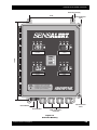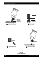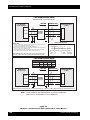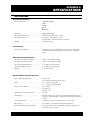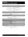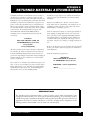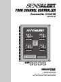
1
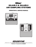
FOUR CHANNEL CONTROLLER
Document No. 7013227M
(Revision H)
LO
HI
LO
HI HI
HI
HI HI
CH 1
CH 2
FAULT
FAULT
METHANE
9 %LEL
OXYGEN
19.3 %VOL
POWER
AC PWR
LO
HI
DC PWR
BACK UP
HI HI
▼
HI
HI HI
CH 3
CH 4
FAULT
FAULT
CHLORINE
0.3 PPM
RESET
BUTTON
LO
AMMONIA
19 PPM
• Push RESET to unlatch a LATCHED ALARM
• Push RESET to silence a local LO ALARM
• Push RESET for 5 seconds to enter CAL MODE
(Push RESET again to exit CAL MODE)
Sensidyne, LP
1000 112th Circle N, Suite 100
St. Petersburg, Florida 33716 USA
(800) 451-9444 • (727) 530-3602 • Fax: (727) 539-0550
web: www.sensidyne.com • e-mail: [email protected]
SENSALERT FOUR CHANNEL CONTROLLER
PACKING LIST & NOTICES
The items listed below are shipped with the SensAlert Four Channel Controller:
•
4–20 mA controller with built-in readout displays,
housed in a NEMA 4X fiberglass enclosure.
•
Operation and Service Manual
Always check to make certain you have received all of the items listed above. If you have any questions or
need assistance, contact your Sensidyne Representative, or call (800) 451-9444 or (727) 530-3602
PROPRIETARY NOTICE
This manual was prepared by Sensidyne, LP exclusively for the owner of the SensAlert Four Channel Controller. The material within this manual is
the proprietary information of Sensidyne, LP and is to be used only to understand, operate, and service the instrument. By receiving this document, the recipient agrees that neither this document nor the information disclosed within nor any part shall be reproduced or transferred, physically, electronically or in any form or used or disclosed to others for manufacturing or for any other purpose except as specifically authorized in
writing by Sensidyne, LP.
COPYRIGHT NOTICE
© 2002, © 2008 Sensidyne, LP. All rights reserved. Information contained in this document is protected by copyright. No part of this document may
be photocopied, reproduced, or translated to another program or system without prior written authorization from Sensidyne, LP.
TRADEMARK NOTICE
Sensidyne, the Sensidyne logo, SensAlert, and the SensAlert logo are registered trademarks of Sensidyne, LP. SensAlarm is a trademark of Sensidyne,
LP. The trademarks and service marks of Sensidyne, LP are protected through use and registration in the United States.
SOFTWARE LICENSE
The software included with the SensAlert is the property of Sensidyne, LP and shall remain the property of Sensidyne, LP in perpetuity. The software is protected by U.S. and international copyright laws and is licensed for specific use with the SensAlert Four Channel Controller. The user
may NOT reverse-engineer, disassemble, decompile, or make any attempt to discover the source code of the software. The software may NOT be
translated, copied, merged or modified in any way. The user may NOT sublicense, rent, or lease any portion of the software. The right to use the
software terminates automatically if any part of this license is violated.
DISCLAIMER
SENSIDYNE, LP ASSUMES NO RESPONSIBILITY WHATSOEVER, TO ANY PARTY WHOSOEVER, FOR
ANY PROPERTY DAMAGE, PERSONAL INJURY, OR DEATH RECEIVED BY OR RESULTING FROM, IN
WHOLE, OR IN PART, THE IMPROPER USE, INSTALLATION, OR STORAGE OF THIS PRODUCT BY
THE USER, PERSON, FIRM, ENTITY, CORPORATION OR PARTY NOT ADHERING TO THE INSTRUCTIONS AND WARNINGS OR NOT ADHERING TO ALL FEDERAL, STATE, AND LOCAL ENVIRONMENTAL AND OCCUPATIONAL HEALTH AND SAFETY LAWS AND REGULATIONS.
THE SELLER SHALL NOT BE LIABLE FOR DIRECT, INDIRECT, CONSEQUENTIAL, INCIDENTAL OR
OTHER DAMAGES RESULTING FROM THE SALE AND USE OF ANY GOODS AND SELLER’S LIABILITY HEREUNDER SHALL BE LIMITED TO REPAIR OR REPLACEMENT OF ANY GOODS FOUND DEFECTIVE. THIS WARRANTY IS IN LIEU OF ALL OTHER WARRANTIES, EXPRESSED OR IMPLIED, INCLUDING BUT NOT LIMITED TO THE IMPLIED WARRANTIES OF MERCHANTABILITY AND FITNESS
FOR USE OR FOR A PARTICULAR PURPOSE WHICH ARE EXPRESSLY DISCLAIMED.
Sensidyne Document No. 7013227M (Rev H)
PRELIMINARY
3
SENSALERT FOUR CHANNEL CONTROLLER
TABLE
OF
CONTENTS
• PREFACE
• Packing List & Notices .............................................................................................................3
• WARNINGS ............................................................................................................................. 7
SECTION ONE: INTRODUCTION
1.1
Overview ...................................................................................................................... 8
1.2
Components ................................................................................................................. 9
1.2.1
1.2.2
1.2.3
Controller Housing ......................................................................................... 9
Display PCB .................................................................................................... 9
Bottom PCB .................................................................................................... 9
1.3
Operator Buttons ........................................................................................................ 11
1.4
Controller Screens ....................................................................................................... 12
1.4.1
1.4.2
System Screens .............................................................................................. 12
Channel Screens ............................................................................................ 12
SECTION TWO: INSTALLATION
2.1
Mounting & Wiring ..................................................................................................... 15
2.1.1
2.1.2
2.1.3
2.1.4
4
Terminal Designations .................................................................................. 15
Jumpers .......................................................................................................... 16
Fuses ..............................................................................................................16
Potentiometers ............................................................................................... 16
2.2
Wiring Procedure ........................................................................................................ 18
2.3
Initial Start-Up ..............................................................................................................21
PRELIMINARY
Sensidyne Document No. 7013227M (Rev H)
SENSALERT FOUR CHANNEL CONTROLLER
TABLE OF
CONTENTS
SECTION THREE: OPERATION
3.1
Main Screen .................................................................................................................25
3.2
View Alarm Settings (Menu #1) .................................................................................. 25
3.3
Entering a Password .................................................................................................... 25
3.4
Entering Calibration Mode ..........................................................................................26
SECTION FOUR: CHANGING ALARM SETTINGS
•
Changing Alarm Settings .............................................................................................28
SECTION FIVE: USING SET-UP & DIAGNOSTICS
5.1
Set-Up (Menu #3) ........................................................................................................ 29
5.1.1
5.1.2
5.1.3
5.1.4
5.1.5
5.1.6
5.1.7
5.2
Enable/Disable a Channel ............................................................................. 29
Set Calibration Delay ..................................................................................... 29
Changing the Password................................................................................. 30
Changing the RS-485 Address ....................................................................... 30
Setting Alarm Latching .................................................................................. 32
Energize Relay ............................................................................................... 32
Adjusting the Zero Point ............................................................................... 32
Diagnostics (Menu #4) ................................................................................................33
5.2.1
5,2.2
Self-Test .......................................................................................................... 33
Relay Check ...................................................................................................33
SECTION SIX: MAINTENANCE & SERVICE
6.1
Adjusting the Output ...................................................................................................34
6.2
Replacing the Power Supply ...................................................................................... 34
6.3
Replacing the Display PCB ......................................................................................... 35
6.4
Replacing the Bottom PCB ......................................................................................... 35
SECTION SIX: PARTS LIST
• Controller Parts .....................................................................................................................36
Sensidyne Document No. 7013227M (Rev H)
PRELIMINARY
5
SENSALERT FOUR CHANNEL CONTROLLER
LIST OF
FIGURES & TABLES
APPENDICES
• Appendix A: Specifications
• General Specifications ............................................................................................ 37
• Appendix D: Troubleshooting Guide
• Troubleshooting Guide ..........................................................................................38
• Appendix E: Returned Material Authorization
• Returned Material Authorization ............................................................................ 39
• Service Options ......................................................................................................39
LIST OF FIGURES
Section One: Introduction
1.1
1.2
1.3
Display PCB .............................................................................................................10
Controller Menu System: Main Screens ................................................................. 13
Controller Menu System: Individual Channel Screens .......................................... 14
Section Two: Installation
2.1
2.2
2.3
2.4
2.5
2.6
2.7
Controller Wiring: Bottom PCB ............................................................................. 17
Attaching the Mounting Feet ................................................................................... 18
Controller Mounting ................................................................................................19
Terminal Wiring Guide ............................................................................................ 20
Wiring to a SensAlert Transmitter (with Intrinsic Safety Barrrier) ......................... 22
Wiring to a SensAlert Transmitter (without Intrinsic Safety Barrrier) ................... 23
Wiring to a non-SensAlert Transmitter (without Intrinsic Safety Barrrier) ............ 24
Section Three: Operation
3.1
Entering a Password ................................................................................................27
Section Five: Using Set-Up & Diagnostics
5.1
6
Changing a Password .............................................................................................. 31
PRELIMINARY
Sensidyne Document No. 7013227M (Rev H)
SENSALERT FOUR CHANNEL CONTROLLER
WARNINGS
READ AND UNDERSTAND ALL WARNINGS BEFORE USE
Read and understand ALL warnings before using this product. Failure to read, understand, and
comply with ALL warnings could result in property damage, severe personal injury, or death.
Read and understand ALL applicable Federal, State, and Local environmental health and safety
laws and regulations, including OSHA. Ensure complete compliance with ALL applicable laws
and regulations before and during use of this product.
UNDER NO CIRCUMSTANCES should this product be used except by qualified, trained, technically competent personnel and not until the warnings, Operation and Service Manual, labels,
and other literature accompanying this product have been read and understood.
This product should NOT be used in any way other than specified in this manual.
DO NOT remove, cover, or alter any label or tag on this product, its accessories, or related
products.
DO NOT operate this product should it malfunction or require repair. Operation of a malfunctioning product, or a product requiring repair may result in serious personal injury or death.
DO NOT attempt to repair or modify the instrument, except as specified in the Operation and
Service Manual. Contact the Sensidyne Service Department to arrange for a Returned Material
Authorization (RMA).
ONLY use genuine SENSIDYNE® replacement parts when performing any maintenance procedures
provided in this manual. Failure to do so may seriously impair instrument performance. Repair or
alteration of the product beyond the scope of these maintenance instructions, or by anyone other
than a certified SENSIDYNE® serviceman, could cause the product to fail to perform as designed and
persons who rely on this product for their safety could sustain severe personal injury or death.
AC (Earth) ground MUST terminate on each controller’s ground terminal to prevent an electric
shock-hazard. A PCB board mounted ground lug is supplied with each unit.
Operation of the alarm relays above their contact ratings may result in false alarms or relay failure.
CAUTIONARY NOTE
The output signal to the recorder, or other data gathering device, is always “live.” That is, the display
reading is transmitted directly through the recorder output to whatever peripheral device is attached
to the controller. Any recorder or other data gathering device should be turned off during
calibration.
Sensidyne Document No. 7013227M (Rev H)
PRELIMINARY
7
SENSALERT FOUR CHANNEL CONTROLLER
SECTION ONE
INTRODUCTION
1.1
OVERVIEW
IMPORTANT
You must read this manual in its entirety to ensure proper
operation of the controller.
This manual provides specific information concerning
the installation, operation, and maintenance of the
Sensidyne SensAlert Controller.
The SensAlert Controller, when used with a Sensidyne
external I.S. barrier (PNº 7013263), is designed to operate an intrinsically safe SensAlert transmitter in areas
classified Class I, Division 1, Groups A, B, C, D; Class II,
Division 1, Groups E, F, G.
The Sensidyne SensAlert Controller is an integral part
of the SensAlert Gas Monitoring System. The SensAlert
Controller, housed in a NEMA 4X enclosure, provides
separate single pole double throw (SPDT) relays for
each alarm condition, plus one common relay for a
fault condition. It also serves as an interface when an
event needs to be relayed to a peripheral device, such
as a building fire alarm system. The SensAlert Controller displays can display gas levels in either ppm, %vol,
or %LEL, depending on the installed sensor.
The power supply for the controller has been designed
to operate at 90-265 VAC, with the capability of adding a 24 Vdc backup power supply.
Some of the features of SensAlert Four Channel Controller include:
•
•
•
•
•
•
•
•
8
Auto-recognition of sensors
Lo, Hi, HiHi, & Fault alarms
User-selectable alarm levels
Three relay contacts per sensor
Lockout/tagout designed case
RS-485 serial output
4-20 mA / 1-5 volt output
Password protection
PRELIMINARY
Sensidyne Document No. 7013227M (Rev H)
SENSALERT FOUR CHANNEL CONTROLLER
1.2
1.2.1
COMPONENTS
Controller Housing
The NEMA 4X enclosure is made of high-grade, fiberglass reinforced polyester resin matting. The enclosure
provides a weather-resistant and water-resistant barrier
between the internal electronics and the ambient environment. The controller cover is secured to the housing with 2 quick release latches. Each latch has a
small circular knockout that allows the case to be
locked or tagged to prevent unauthorized entry.
The Reset switch is located on the bottom of the controller housing (refer to Figure 2.1). The switch can be
used to (1) unlatch a latched alarm, (2) silence a local
Lo Alarm, or (3) enter Calibration Mode (when
pressed for 5 seconds).
The Alarm Buzzer is located on the bottom of the
controller housing, next to the cable glands. The
alarm buzzer is used for the Local Alarm.
1.2.2
Display PCB
The Display PCB contains the large, 3-digit LED displays, the LCD displays, and the operator buttons that
control the menu system. The Display PCB connects
to the Bottom PCB via a 20-pin flex cable. The components on the Display PCB are described as follows.
• Liquid Crystal Display
The Liquid Crystal Display (LCD) is a 16 character, 2line display located behind the front cover of the controller enclosure (see Figure 1.1). During normal operation, the display shows the gas name and gas concentration (in ppm, %LEL, or %vol) for the sensor installed at the transmitter. The display is also used for
viewing and changing various features of the
controller (e.g., alarm settings, passwords, etc.).
During alarm and fault conditions, the display shows
status messages on Line 2 describing the nature of the
condition (e.g., Lo Alarm, Missing Sensor, etc).
• Operator Buttons
The 5 Operator Buttons a control the menu system.
The menu system allows you to view and change
alarm settings, change system features, and perform
diagnostics. A detailed description of the menu system
and operator buttons can be found in Sections 1.3 &
1.4.
1.2.3
Bottom PCB
The Bottom PCB (see Figure 2.1) is attached to the inside bottom of the controller housing. The components located on the Bottom PCB are described below.
The Bottom PCB is populated with 11 terminal blocks.
Each terminal block consists of a base block and a
keyed, removable terminal plug that facilitates wiring.
Terminal wiring designations are described in Section
Two.
The Bottom PCB also contains jumpers, AC & DC
fuses, and a current limiting 4 channel power supply.
Sensidyne Document No. 7013227M (Rev H)
PRELIMINARY
9
SENSALERT FOUR CHANNEL CONTROLLER
Hinged Sandoff
(under PCB)
Channel &
Fault LED
(4 places)
LO
HI
Mounting
Screw
LCD Display
16 Char X 2 Line
(4 places)
LO
HI HI
HI
HI HI
CH1
CH2
OXYGEN
OXYGEN
19.3 %VOL
%VOL
19.3
OXYGEN
METHANE
9 %LEL
19.3
%VOL
Power LEDs
LO
HI
LO, HI, & HIHI
Alarm LEDs
(4 PLACES)
AC PWR
HI HI
LO
HI
HI HI
DC BACK UP
CH3
CH4
OXYGEN
CHLORINE
.3 PPM
19.3
%VOL
CARBON MONOXIDE
19 PPM
Operator
Buttons
CHANNEL
SELECT
NEXT
▲ UP
SELECT
▼ DOWN
Hinged Standoff
(under PCB)
Mounting
Screw
Figure 1.1
Display PCB
10
PRELIMINARY
Sensidyne Document No. 7013227M (Rev H)
SENSALERT FOUR CHANNEL CONTROLLER
1.3
OPERATOR BUTTONS
Figures 1.2 and 1.3 show the operator buttons that
control the menu system.
▲ UP & ▼ DOWN
The
▲UP
The buttons are described below.
•
To scroll “up” or “down” different menu lists.
Each screen indicates which type of scrolling is
available by displaying either an ▲ or ▼ arrow.
When both arrows appear on the display, up and
down scrolling is available.
•
To increase or decrease a value shown on the
screen (such as an alarm setting or a password
code).
CHANNEL SELECT
The CHANNEL SELECT button is used to access a channel for system programming.
NEXT
The
NEXT
•
Pushing the NEXT button,during normal operation
displays the current alarm settings for all 4 channels (see Figure 1.2).
•
button has two funrctions:
Pressing the NEXT button after selecting a channel
moves you through the Set Alarm, Set-up, and Diagnostics screens for that channel (see figure 1.3).
Sensidyne Document No. 7013227M (Rev H)
and
▼DOWN
buttons have two purposes.
SELECT
The SELECT button is used to select an item from a
menu list after you have scrolled to that item using the
▲UP or ▼DOWN buttons.
The SELECT button also is used to accept a value after
it has been changed (e.g., a new alarm setting). It is
similar to the RETURN/ENTER key on a keyboard.
PRELIMINARY
11
SENSALERT FOUR CHANNEL CONTROLLER
1.4
CONTROLLER MENUS
Figures 1.2 and 1.3 show the primary controller
screens: Main Screen, View Alarms (#1), Set Alarms
(#2), Set-Up (#3), and Diagnostics (#4). There is also an
Enter Password screen that appears if a password has
been set. The CHANNEL SELECT and NEXT buttons are
used to navigate through the menu screens.
1.4.1
System Screens
• Main
The Main Screen is the primary screen during normal
operation. It displays the gas name and gas concentration (in ppm, %LEL, or %VOL). During alarm or fault
conditions, the Main Screen displays warning messages
on Line 2. These messages are shown in Figure 1.3.
• View Alarms (#1)
The View Alarms Screen shows the current settings for
the Lo, Hi, and HiHi alarms. This screen is always available whether or not a password has been set. The
alarm settings can be viewed by pressing the NEXT button during normal operation.
1.4.2
Channel Screens
The following screens are available for each of the
four controller channels.
• Set Alarms (Menu #2)
This screen allows you to change the Lo, Hi, and Hi Hi
alarm settings. It also lets you set the alarms to their default (factory-set) values.
• Set-Up (Menu #3)
The Set-Up Screen allows you to change the following
SensAlert features:
•
•
•
•
•
•
•
Enable/Disable a Channel
Set Calibration Delay
Change the Password
Change the RS-485 Address (custom order)
Set Alarm Latching (latched vs. unlatched)
Energize Relay
Adjust the Zero Point
• Diagnostics (Menu #4)
• Enter Password
This screen appears after you press the CHANNEL SELECT button and a password has been set. You must
enter a valid 4-digit password to access the Set Alarms,
Set-Up, and Diagnostics screens in any of the 4 channels. The unit is shipped from the factory without a
password.
12
The Diagnostics screen contains routines that check the
state of the controller. These include a Self-Test (similar to the self-test conducted during initial start-up)
and an Alarm Relay Check.
PRELIMINARY
Sensidyne Document No. 7013227M (Rev H)
Sensidyne Document No. 7013227M (Rev H)
PRELIMINARY
AMMONIA
19 PPM
CHLORINE
0.3 PPM
0.5
HIHI
1.5
REFERS TO MENU#
HI
1.0
CHANNEL 3
1
HIHI
50
LO
10
HI
20
HIHI
50
CHANNEL 4
HI
20
LO
10
1
LO
10
HI
20
CHANNEL 2
VIEW ALARM SETTINGS
CHANNEL 1
1 LO
1
CHANNEL 4
CHANNEL 3
QUICK VIEW
METHANE
9 %LEL
OXYGEN
19.3 %VOL
• Line 1: Sensor Name
• Line 2: Sensor Value
or status message:
CHANNEL 2
NORMAL OPERATION SCREENS
CHANNEL 1
▲ UP
2 SCROLL & SELECT
▼ LO ALARM
CHANNEL 4
CHANNEL 2
▼ DN
SELECT
SELECT
CHANNEL
SELECT
Figure 1.2
Controller Menu System: Main Screens
CHANNEL 3
CHANNEL 1
NEXT
CHANNEL
SELECT
MAINTENANCE
Use ▲ & ▼ buttons to
set code, then press
SELECT.
ENTER PASSWORD
▲
▼ 0000
CHANNEL 1
This screen appears if password enabled.
2 SCROLL & SELECT
▼ LO ALARM
CHANNEL 3
CHANNEL 1
CHANNEL
SELECT
CHANNEL 3
CHANNEL 1
CHANNEL
SELECT
CHANNEL 3
2 SCROLL & SELECT
▼ LO ALARM
CHANNEL 1
CHANNEL 4
CHANNEL 2
CHANNEL 4
2 SCROLL & SELECT
▼ LO ALARM
CHANNEL 2
CHANNEL 4
CHANNEL 2
SENSALERT FOUR CHANNEL CONTROLLER
13
SENSALERT FOUR CHANNEL CONTROLLER
OPERATOR BUTTONS
CHANNEL
SELECT
• Selects active channel
for programming
NEXT
• Advances to next Menu
SELECT
▲ UP
• Scrolls “up” a menu list
• Increases a value
▼ DOWN
MAIN SCREEN
• Selects item from menu
• Accepts changed value
• Scrolls “down” a menu list
• Decreases a value
SET ALARMS SCREEN
(Menu #2)
PASSWORD SCREEN *
CARBON MONOXIDE
5 PPM
2 SCROLL & SELECT
▼ LO ALARM
ENTER PASSWORD
▲
■=0
▼ ■000
CHANNEL
SELECT
• Line 1: Sensor Name
• Line 2: Sensor Value
OR
"LOOP-FAIL"
"LO ALARM"
"HI ALARM"
"HIHI ALARM"
"LO ALARM LATCH"
"HI ALARM LATCH"
"HIHI ALARM LATCH”
SELECT
• Lo Alarm
• Hi Alarm
• HiHi Alarm
• Default
• Resume
Use ▲ & ▼ buttons to set
code, then press SELECT.
* Screen appears if password enabled
REFERS TO MENU#
NEXT
DIAGNOSTICS SCREEN
(MENU #4)
MAIN SCREEN
SET-UP SCREEN
(Menu #3)
3
4 SCROLL & SELECT
▼ SELF TEST
CARBON MONOXIDE
5 PPM
NEXT
SCROLL & SELECT
ENABLE/DISABLE
▼
NEXT
• Self Test
• Relay Check
• Resume
• Enable/Disable
• Set Cal Delay
• Change Password
• RS-485 Addr
• Alarm Latching
• Energize Relay
• Adjust Zero
• Resume
Figure 1.3
Controller Menu System: Individual Channel Screens
14
PRELIMINARY
Sensidyne Document No. 7013227M (Rev H)
SENSALERT FOUR CHANNEL CONTROLLER
SECTION TWO
INSTALLATION
2.1
MOUNTING & WIRING
The SensAlert Controller is designed to be wall
mounted. Four mounting feet are supplied. The feet
mount to the back of the enclosure and are secured to
the unit by 10-32 screws (3/8” in length). The feet must
be positioned vertically (refer to Figures 2.2 & 2.3).
The controller is wired to transmitters through EMT
connectors positioned at the bottom of the enclosure.
The EMT connectors prevent moisture from entering
the enclosure. The controller must be wired using
shielded twisted pair cable (with the shield tied to earth
ground) to achieve maximum RFI/EMI immunity.
24V wire connects to the Positive Power on the
transmitter.
4–20 mA IN signal wire connects to the 4–20 mA
Signal Output terminal on the transmitter.
Power Return (PWR RTN) wire connects to the
Power Return terminal on the transmitter (3-wire
transmitters only).
NOTE
Use only U.L. listed or recognized conduit hubs that have
the same or better environmental rating as the enclosure. Conduit hubs must be connected to the conduit
before being connected to the enclosure.
2.1.1
• Transmitter Power To Sensors (J8-J11)
This terminal is used to wire the controller to the
transmitter. A simplified wiring diagram showing how
the controller is wired to the transmitter is shown in
Figure 2.6). The terminals are wired as follows:
Terminal Designations
Wiring terminals are located on the Main (bottom) PCB.
They are designated as follows (see Figure 2.1):
Audible Alarm (J5)
The local alarm buzzer is factory wired. The local alarm
buzzer is located at the bottom of the controller housing, on the outside of the case.
Reset Switch (J4)
The Reset Switch is factory-wired. The switch is located
on the bottom of the controller housing, on the outside
of the case.
AC Power To Controller (J2)
The controller is wired to an AC power source through
these terminals. The terminal marked LO is used for the
neutral AC wire. The terminal marked HI is used for
the hot AC wire. The middle terminal is not used.
• 4–20 mA Output (J6)
4-20 mA output is available for external devices for
each of the 4 channels. Each output can be independently changed from 4-20 mA to 1-5 Volts using the
jumpers at JP1–JP4.
In addition, each channel output can be adjusted by
potentiometers VR1-VR4 for increased accuracy.
• 24 Vdc Battery Backup (J3)
A DC battery backup can be wired to controller. The
battery backup is wired as follows:
POS wire connects to the positive (+) terminal on
a 20-26 Vdc battery backup.
RTN (Power Return) connects to the negative (–)
terminal on a 20-26 Vdc battery backup.
There is fuse diode protection incorporated within the
unit such that reversing the wiring of the backup supply will not do any damage, but will merely burn out
the fuse. The backup supply must have an output of
20–26 Vdc @ 2 1/2 amp.
NOTE
When wiring the controller to a permanent A.C. source,
the A.C. source circuit breaker and/or switch must be IEC
approved. The circuit breaker and/or switch must be near
the unit and marked as the disconnect device for the unit.
Sensidyne Document No. 7013227M (Rev H)
PRELIMINARY
15
SENSALERT FOUR CHANNEL CONTROLLER
• Fault Relay (J12)
The Fault Alarm Relay (J12) acts in common to all
four channels and the system. It is factory-set (default)
to be energized during normal operation. The markings
at J12 reflect this intention. Therefore, unless the operation is changed by the user, the fault relay’s SPDT
Form C contact acts as follows:
The Hi Hi Alarm Relays are factory-set to be normally de-energized:
ENERGIZED
DE-ENERGIZED
(Normal)
NO
COM
NO
COM
NC
NC
No Alarm
No Alarm
ENERGIZED
(Normal)
NC
• RS-485 Output (J7)
The RS-485 Output terminals are designated as follows:
COM
NO
No Alarm
VCC
A
B
GND
• Alarm Relays (J8-J11)
Each channel has a set of 3 alarm relays which act in
accordance with the settings for their channel. These
relays each have one SPDT Form C contact. Unless the
factory setting (default) of de-energized during normal
operation is changed by the user, the alarm relays act
as follows:
Exact RS-485 functions to be determined for specific
applications.
2.1.2
The Lo Alarm Relays are factory-set to be normally
de-energized in normal operation:
ENERGIZED
DE-ENERGIZED
(Normal)
NO
COM
1-5 Volt Output Select (JP1-JP4)
The analog output signal from the controller to an external device is factory set for 1–5 volts. This allows
output to a chart recorder or computer-based recorder
device. The jumpers are designated as follows:
NO
COM
NC
No Alarm
The Hi Alarm Relays are factory-set to be normally
de-energized in normal operation:
Removing the jumper changes the output to 4–20 mA
for any channel using external termination.
DE-ENERGIZED
(Normal)
2.1.3
NO
COM
Fuses
NO
COM
NC
No Alarm
JP1 = Channel 1
JP2 = Channel 2
JP3 = Channel 3
JP4 = Channel 4
NC
No Alarm
ENERGIZED
Jumpers
NC
No Alarm
•
AC Fuse: 4 amp, fast blow (Location: FS1).
•
DC Fuse: 3 amp, fast blow (Location: F1).
2.1.4
Potentiometers
The accuracy of the analog output signal from the
controller can be adjusted by VR1-VR4. Clockwise adjustments increase the output level for that specific
channel. Counterclockwise adjustments decrease it.
The potentiometers are designated as follows:
VR1
VR2
VR3
VR4
16
PRELIMINARY
=
=
=
=
Channel
Channel
Channel
Channel
1
2
3
4
Sensidyne Document No. 7013227M (Rev H)
SENSALERT FOUR CHANNEL CONTROLLER
Output to External Device (J6)
(4-20 mA or 1-5 V)
Reset Switch (J4)
(factory wired)
Audible Alarm (J5)
(factory wired)
Fault Alarm
(energized in normal operation)
NO = Normally Open
NC = Normally Closed
Alarms
(Lo, Hi, & HI-HI each channel)
CHANNEL 1
RS-485 functions to
be determined by
specific application
J7 RS-485
VCC
A
B
GND
J12
NC
COM
NO
FAULT
NORMALLY ENERGIZED
CHANNEL 2
CHANNEL 3
CHANNEL 4
HI-HI
HI-HI
NO
COM
NC
NO
COM
NC
HIGH
HIGH
NO
COM
NC
NO
COM
NC
LOW
LOW
NO
COM
NC
24V
4-20mA IN
PWR RTN
NO
COM
NC
24V
4-20mA IN
PWR RTN
J8
J10
J9
J11
ALARM
J5
Transmitters
(PWR RTN for
3-wire systems only)
RESET
J4
VR3
J6 4-20 mA OUT
CH4
GND
CH3
GND
CH2
GND
CH1
GND
JP4
JP3
VR1
VR2
JP2
JP1
Output Adjust Potentionmeters
VR1 = Channel 1
VR2 = Channel 2
VR3 = Channel 3
VR4 = Channel 4
AC Power Source (J2)
HOT
4-20 mA Output Circuit (JP1-JP4)
Jumpers installed: 1-5 volts
Jumpers removed: 4-20 mA
POS
RTN
J3
VR4
Neutral
3 AMP
24 VDC
Battery B/U
J2
AC Fuse, 4 amp (FS1)
F1
AC
POWER SUPPLY
DC Connector
to PCB
AC Connector
to PCB
Safety Ground
[install ground wire
from power source here]
24 VDC Battery
Back-Up (J3)
DC Fuse, 3 amp (F1)
Figure 2.1
Controller Wiring: Bottom PCB
Sensidyne Document No. 7013227M (Rev H)
PRELIMINARY
17
SENSALERT FOUR CHANNEL CONTROLLER
2.2
WIRING PROCEDURE
Mount the controller to the wall using the four
mounting feet provided. The feet are positioned vertically and then mounted to the back of the controller
housing with four 10-32 screws (see Figure 2.2).
5) Insert a terminal wire into the plug [Figure 2.4-B].
Note: Wires are inserted in the side of 2-, 3-,
and 4-position terminal plugs, and in the top
of 8- and 12-position terminal plugs.
Secure the controller housing to the wall with the appropriate anchoring hardware. The mounting dimensions are shown in Figure 2.3.
6) Secure the wire by tightening the terminal screw
with a small flat blade screwdriver [Figure 2.4-C].
Wire the controller according to the terminal designations described in Section 2.1.1 and shown in Figure
2.1.
Wire the controller as follows (refer to Figures 2.1,
2.4, 2.5, 2.6, & 2.7):
1) Open the quick-release latches on the controller
housing and open the cover.
2) Unscrew the two right-hand mounting screws on
the Display PCB and swing it to the left (the
board is attached to 2 hinged standoffs.
3) Locate a terminal block you wish to wire.
4) Remove the terminal plug from the terminal
block [Figure 2.4-A]
7) Complete Steps 5 & 6 for the remaining wires for
that terminal plug.
8) Replace the terminal plug on the terminal block
[Figure 2.4-D].
9) Complete Steps 3–8 for the remaining terminal
blocks.
Make certain you install the ground (earth) wire
under the lower level washer on the safety ground
terminal. Terminate the shields of the transmitter
cable under the upper level washers on the ground
terminal.
10) Install the ground wire (earth) to safety ground
(see Figure 2.1).
11) Close the Display PCB and secure it with the
mounting screws.
12) Close the controller cover and secure the quick
release latches.
10-32 screw
Mounting
Foot
Controller
Back
Figure 2.2
Attaching the Mounting Feet
18
PRELIMINARY
Sensidyne Document No. 7013227M (Rev H)
SENSALERT FOUR CHANNEL CONTROLLER
Mounting Feet (4)
8.00”
LO
HI
Quick-Release
Latch
LO
HI HI
HI
HI HI
CH 2
CH 1
FAULT
FAULT
CHANNEL 1
CHANNEL 2
METHANE
9 %LEL
OXYGEN
19.3 %VOL
12.94”
POWER
AC PWR
LO
HI
DC PWR
BACK UP
HI HI
LO
HI
HI HI
CH 3
CHANNEL 3
CH 4
FAULT
CHANNEL 4
CHLORINE
0.3 PPM
RESET
BUTTON
▼
FAULT
AMMONIA
19 PPM
• Push RESET to unlatch a LATCHED ALARM
• Push RESET to silence a local LO ALARM
• Push RESET for 5 seconds to enter CAL MODE
(Push RESET again to exit CAL MODE)
Quick-Release
Latch
Reset Button
Alarm Buzzer
EMT Connectors
(optional)
Figure 2.3
Controller Mounting
Sensidyne Document No. 7013227M (Rev H)
PRELIMINARY
19
SENSALERT FOUR CHANNEL CONTROLLER
TOP VIEW
Terminal Plug
MAIN BOARD
Terminal Block
(with guide pins)
SIDE VIEW
A
Pull on terminal plug
to remove it from board
Insert wire into
terminal plug
B
MAIN BOARD
C
Tighten terminal screw
with flat blade screwdriver
D
Install terminal plug on
appropriate terminal block
Figure 2.4
Terminal Wiring Guide
20
PRELIMINARY
Sensidyne Document No. 7013227M (Rev H)
SENSALERT FOUR CHANNEL CONTROLLER
2.3
INITIAL START-UP
After controller wiring has been completed, make certain the transmitter has been properly wired to the controller and that no sensor is installed in the transmitter.
Sensor should be installed in the transmitter AFTER the
transmitter has been powered up.
5) Enable each channel as follows:
a) Press the NEXT button to move to the Set-Up
screen (Menu #3).
1) Check Figure 2.5. If an optional intrinsic safety barrier is used, make certain it is properly wired.
b) Press SELECT to choose Enable/Disable (this
item is always shown first when going to the
Set-Up screen). The screen will show “Disabled”.
2) Apply power to the controller. During start-up, a
series of warning and self-test screens appear, followed by “Channel Disabled” displayed in each of
the 4 channel displays.
c) Press the ▼DOWN button to change the status to
“Enabled”. Press SELECT to enable the channel.
This is expected. All units are shipped from
the factory with their channels disabled. This
is to avoid a “Missing Sensor” fault (with audible alarm) during initial start-up.
3) Once the controller and transmitters have been
powered up, install sensors in the transmitters.
4) Press CHANNEL SELECT to bring up the Set Alarms
screen (“2 Scroll & Select.......Lo Alarm”) for Channel 1.
d) Press CHANNEL SELECT to bring up the Set
Alarms screen for Channel 2.
e) Repeat Steps 5a–5d for each of Channels 2, 3,
& 4 that are to be used.
f)
When all channels which are to be used have
been enabled, press CHANNEL SELECT until the
unit returns to the Main Screen.
6) The unit will perform channel initialization for
each of the 4 channels. After initialization, the unit
will begin Normal Operation.
7) If you want to adjust the output at this point, go
to Section 6.1.
Sensidyne Document No. 7013227M (Rev H)
PRELIMINARY
21
SENSALERT FOUR CHANNEL CONTROLLER
2-WIRE TRANSMITTER WIRING DIAGRAM
Maximum wire length 1 is 2000 feet for all wire sizes
SAFE AREA
SensAlert Flour
Channel Controller
+24V nom
4-20 mA
HAZARDOUS AREA
4
Sensidyne
C
2 I.S. aBarrier
5
P/N 7013263
aL
3
6
SensAlert Transmitter
(2-Wire)
1
+24V (1)
4-20 mA (2)
NC
CABLE PARAMETERS
BARRIER NOTES:
1. Output current must be limited by a resistor such that the output voltage vs.
current plot is a straight line between Voc and Isc.
2. Barrier must be installed as instructed by manufacturer.
3. Selected barrier intrinsically safe circuits shall be approved for Class I Groups
A, B, C, D and Class II, Groups E, F, G.
4. Terminate barrier earth ground to the ground bus of the power distribution
panel. Resistance to ground must not be greater than one ohm.
If electrical parameters of cable unknown,use 60 pf/ft and 0.2µh/ft
Terminals Vmax
1–2
30 Vdc
Imax
Ci
Li
125 mA
.013 µF
1.1 mH
Class I, Div 1, Grps A, B, C, D. Class II, Div 1, Grps E, F, G.
Vmax ≥ Voc
Imax ≥ Isc
NOTE: All intrinsically safe wiring shall be kept separate from all other wiring. Use of
cable tray or conduit accetable. Refer to Article 504 of the National Electrical Code.
Ci+ cable ≤ Ca (barrier)
Li + cable ≤ La (barrier)
3-WIRE TRANSMITTER WIRING DIAGRAM
Maximum Wire Length1
AWG
24
22
20
3-Wire CMB
50
75
100
3-Wire Toxic 1500
2000
2000
SAFE AREA
SensAlert Four
Channel Controller
+24V nom
4-20 mA
1
2
18
200
2000
HAZARDOUS AREA
4
Sensidyne
I.S. Barrier
+24V (1)
5
4-20 (2)
P/N 7013263
RTN
3
SensAlert Transmitter
(3-Wire)
6
PWR RTN (3)
NOTE: All intrinsically safe wiring shall be kept separate from all other wiring. Use of cable tray or conduit accetable. Refer to Article 504 of the National Electrical Code.
NOTE 1: Twisted, stranded wire with shield (grounded on one end only) is recommended.
Distance is in feet. To obtain distance in meters multiply by 0.3.
Figure 2.5
Wiring to a SensAlert Transmitter (with Intrinsic Safety Barrier)
22
PRELIMINARY
Sensidyne Document No. 7013227M (Rev H)
SENSALERT FOUR CHANNEL CONTROLLER
2-WIRE TRANSMITTER WIRING DIAGRAM
Maximum Wire Length1
AWG
24
22
20
2-Wire Toxic 10,000
---
18
--
SensAlert Four
Channel Controller
SensAlert Transmitter
(2-Wire)
+24V
+24V (1)
4-20 mA
4-20 mA (2)
RTN
see Note 1
3-WIRE TRANSMITTER WIRING DIAGRAM
3-Wire
3-Wire
3-Wire
3-Wire
Maximum
AWG
24
CMB
1500
Toxic 4000
Digital 750
IR
900
Wire Length1
22
20
2500
4000
6000 10,000
1250
2000
1500
2500
18
6000
-3500
4000
SensAlert Transmitter
(3-Wire)
SensAlert Four
Channel Controller
+24V
+24V (1)
4-20 mA
4-20 (2)
RTN
PWR RTN (3)
see Note 1
Note: The SensAlert Controller has not yet
been classified by Underwiters Laboratory, Inc.
NOTE 1: Twisted, stranded wire with shield (grounded on one end only) is recommended.
Distance is in feet. To obtain distance in meters multiply by 0.3.
Figure 2.6
Wiring to a SensAlert Transmitter (without Intrinsic Safety Barrier)
Sensidyne Document No. 7013227M (Rev H)
PRELIMINARY
23
SENSALERT FOUR CHANNEL CONTROLLER
2-WIRE TRANSMITTER WIRING DIAGRAM
Maximum Wire Length1
AWG
24
22
20
2-Wire Toxic 7500 10,000
--
18
--
SensAlert Four
Channel Controller
Non-SensAlert
Transmitter
(2-Wire)
+
10 µf
factory
installed
+24V
+24V (1)
4-20 mA (2)
4-20 mA
see Note 1
3-WIRE TRANSMITTER WIRING DIAGRAM
Maximum
AWG
24
3-Wire CMB
1000
3-Wire Toxic 3000
3-Wire Digital 500
3-Wire IR
600
Wire Length1
22
20
2000
3000
5000
8000
750
1250
1000
1750
18
5000
-2000
2500
SensAlert Four
Channel Controller
Non-SensAlert
Transmitter
(3-Wire)
+
10 µf
factory
installed
–
+24V
+24V (1)
4-20 mA
4-20 (2)
RTN
PWR RTN (3)
see Note 1
Note: The SensAlert Controller has not yet
been classified by Underwiters Laboratory, Inc.
NOTE 1: Twisted, stranded wire with shield (grounded on one end only) is recommended.
Distance is in feet. To obtain distance in meters multiply by 0.3.
Figure 2.7
Wiring to a non-SensAlert Transmitter (without Intrinsic Safety Barrier)
24
PRELIMINARY
Sensidyne Document No. 7013227M (Rev H)
SENSALERT FOUR CHANNEL CONTROLLER
SECTION THREE
OPERATION
3.1
MAIN SCREEN
3.2
The Main Screen is the default display for the controller
during normal operation. The Main Screen displays the
gas name and gas concentration (in ppm, %LEL, or
%VOL). An example screen is shown below.
Pushing the NEXT button displays the Lo, Hi, and HIHI
alarm settings for all 4 channels simultaneously. The
menu number appears in the upper left-hand portion
of each display.
CARBON MONOXIDE
10 PPM
During alarm conditions, Line 2 on the Main Screen
also displays warning messages. The following screen
shows a low alarm condition.
CARBON MONOXIDE
LO ALARM
VIEWING ALARM SETTINGS (Menu #1)
1
3.3
LO
25
HI
50
HIHI
75
ENTERING A PASSWORD
If a password has been set, the screen shown in Figure
3.1 appears when the channel select button is pressed.
The “Enter Password” screen always appears in the
Channel 1 LCD display.
The 1st digit on Line 2 is blocked out and ready to be
entered. To enter the 4-digit password follow the steps
below:
Additional messages include:
Loop-Fail [loop power failure]
Lo Alarm [is occurring]
Hi Alarm [is occurring]
HiHi alarm [is occurring]
Lo Alarm Latch [has occurred]
Hi Alarm Latch [has occurred]
HiHi Alarm Latch [has occurred]
1) Use the ▲UP and ▼DOWN buttons to change the 1st
digit to a number from 0-9. Press SELECT to enter
the number.
2) Repeat the procedure for the 2nd digit.
3) Repeat the procedure for the 3rd digit.
4) Repeat the procedure for the 4th digit. When you
press SELECT the entire 4-digit password is entered.
If the number entered matches the password, you gain
access to the Set Alarms, Set-Up, and Diagnostics
screens.
If the number does not match, you are given two more
chances to enter the correct password. If the correct
password is not entered on the third try access is denied (refer to Figure 3.1).
Sensidyne Document No. 7013227M (Rev H)
PRELIMINARY
25
SENSALERT FOUR CHANNEL CONTROLLER
3.4
ENTERING CALIBRATION MODE
To enter calibration mode, press the Reset button (located on the outside bottom of the unit) for 5 seconds.
After time has elapsed, all readings will be “live.”
NOTE
NOTE
Recorder outputs are always “live.”
You cannot enter calibration mode when alarms are
active.
When calibration has been completed, press the RESET
button again to exit Calibration Mode..
The following screen appears
NOTE
2 MIN CAL MODE
RESET TO EXIT
The cal delay can be adjusted from the “Set Cal Delay”
screen in the Set-Up Menu. See Section 5.1.2. Calibration delay can range from 1–30 minutes.
The screen indicates the number of minutes the alarms
will be suppressed while calibration is being performed.
26
PRELIMINARY
Sensidyne Document No. 7013227M (Rev H)
SENSALERT FOUR CHANNEL CONTROLLER
ENTER PASSWORD
“■000” ■=0 ▲
▼
▲ UP or
▼ DOWN
Scroll through numbers
0–9 for 1st digit
ENTER PASSWORD
“■000” ■=3 ▲
▼
Push SELECT to set number
and move to 2nd digit
SELECT
ENTER PASSWORD
“3■00” ■=0 ▲
▼
▲ UP or
▼ DOWN
Scroll through numbers
0–9 for 2nd digit
ENTER PASSWORD
“3■00” ■=7 ▲
▼
Push SELECT to set number
and move to 3rd digit
SELECT
ENTER PASSWORD
“37■0” ■=0 ▲
▼
▲ UP or
▼ DOWN
Scroll through numbers
0–9 for 3rd digit
ENTER PASSWORD
“37■0” ■=4 ▲
▼
Push SELECT to set number
and move to 4th digit
SELECT
ENTER PASSWORD
“3740” ■=0 ▲
▼
▲ UP or
▼ DOWN
Scroll through numbers
0–9 for 4th digit
ENTER PASSWORD
“374■” ■=8 ▲
▼
SELECT
Push SELECT to set final digit
and enter password
If incorrect password entered,
this screen appears
If incorrect password entered
3 times, this screen appears
PASSWORD INVALID
P L E A S E T RY A G A I N
PASSWORD INVALID
ACCESS DENIED
Figure 3.1
Entering A Password
Sensidyne Document No. 7013227M (Rev H)
PRELIMINARY
27
SENSALERT FOUR CHANNEL CONTROLLER
SECTION
FOUR
CHANGING ALARM SETTINGS
The Set Alarms screen (#2) allows you to change the
Lo, Hi, and Hi Hi alarm settings, as well as set the
alarms to their default (factory-set) values.
To change the alarm settings, first push the channel select button. (You may encounter an Enter Password
screen if a password has been set.) A Set Alarms Screen
appears in the Channel 1 display (a “2” appears in the
upper left-hand portion of the display – see below).
To access the Set Alarms screen for Channel 2, push the
channel select button again. Push it a third time to access the Set Alarm screen for Channel 3 and again to
reach Channel 4.
2 SCROLL & SELECT
▼ LO ALARM
Use the ▼DOWN button to scroll down to the Lo, Hi, or
HiHi alarm setting you want to change. (Note: There is
no HiHi alarm for oxygen sensors). Press SELECT. The
screen displays the current alarm setting.
▲
▼
28
LO
30
HI
50
HIHI
75
Repeat this procedure for each alarm you wish to
change.
To change all alarms to their default settings, scroll to
“Default Alarms” and press SELECT. A screen appears to
confirm your action.
SET TO DEFAULTS
UP=YES DOWN=NO
Pressing the ▼DOWN button cancels your action. Pressing the ▲UP button resets the Lo, Hi, and HiHi alarms to
their default settings. A confirmation screen appears
showing the default settings (see below).
LO ALARM
25 PPM
LO
25
Use the ▲UP and ▼DOWN buttons to change the setting.
▲
▼
Press SELECT to enter the new setting. A screen appears
showing the new alarm setting.
HI
50
HIHI
75
To return to the main screen, scroll down to “Resume”
and press SELECT.
LO ALARM
30 PPM
PRELIMINARY
Sensidyne Document No. 7013227M (Rev H)
SENSALERT FOUR CHANNEL CONTROLLER
SECTION FIVE
USING SET-UP & DIAGNOSTICS
5.1
SET-UP (Menu #3)
The Set-Up Screen (“3” appears in the upper left-hand
portion of the display) allows you to change the following SensAlert features:
•
•
•
•
•
•
Enable or Disable a channel
Change the calibration delay time
Enable or change the password code
Set the RS-485 address.
Set alarm relays to “latching” or “non-latching”
Adjust the zero point
Push the NEXT button several times until you reach the
Set-Up screen (you may have to enter a password to
get to this screen).
5.1.1
Enable/Disable a Channel
5.1.2
Set Calibration Delay
3 SCROLL & SELECT
▼ SET CAL DELAY
Press SELECT to choose Set Cal Delay. The current delay (in minutes) is shown on the screen.
SET CAL DELAY
2 MINUTES
▲
▼
Use the ▲UP or ▼DOWN buttons to change the calibration delay time. The delay time can range from 1 minutes to 30 minutes.
3 SCROLL & SELECT
▲
▼ ENABLE/DISABLE
Press SELECT to choose Enable/Disable (this item is always shown first when going to the Set-Up screen).
The current status for that channel is shown on the
screen.
SET CAL DELAY
5 MINUTES
▲
▼
When the desired delay time is displayed on the
screen, press SELECT. To return to the main screen,
scroll down to “Resume” and press SELECT.
Use the ▲UP or ▼DOWN buttons to toggle between “Enabled” and “Disabled”. Press SELECT to set the new
channel status. If the channel status is changed from
“disabled to “enabled” the channel will show a normal
operation screen. If the channel is changed from “enabled” to disabled” the channel will show the following
screen.
CHANNEL
DISABLED
To return to the main screen, scroll down to “Resume”
and press SELECT.
Sensidyne Document No. 7013227M (Rev H)
PRELIMINARY
29
SENSALERT FOUR CHANNEL CONTROLLER
5.1.3
Changing the Password
5.1.4
The unit is shipped from the factory with the password
disabled. You can enable password protection anytime
by changing the password code from its default setting
(“0000”) to any number from 0001 to 9999. To disable
the password, simply reset the password code back to
0000.
To change the password refer to Figure 5.1 and follow
the steps below.
Setting the RS-485 Address
3 SCROLL & SELECT
▲
▼ RS-485 ADDR
Use the ▼DOWN button to scroll down to RS-485 Address, and then press SELECT. The current RS-485 address is displayed on the screen.
RS-485 ADDR IS
▲
“2”
▼
1) Using the ▼DOWN button, scroll to “Change Password” and press SELECT.
3 SCROLL & SELECT
▲
▼ CHANGE PASSWORD
2) The screen shows the current password. The 1st
digit is blocked out and ready to be changed. Use
the ▲UP or ▼DOWN buttons to change the 1st digit
to a number from 0-9. Press SELECT to set the number.
Use the ▲UP or ▼DOWN buttons to change the RS-485
address. The RS-485 address can range from 0 to 15.
Press SELECT to enter the new address.
NEW RS-485 ADDR
13
To return to the main screen, scroll down to “Resume”
and press SELECT.
3) Repeat the procedure for the 2nd digit.
4) Repeat the procedure for the 3rd digit.
5) Repeat the procedure for the 4th digit. When you
press SELECT the entire 4-digit password is now set.
A confirmation appears showing you the new password.
30
3.4
PRELIMINARY
Sensidyne Document No. 7013227M (Rev H)
SENSALERT FOUR CHANNEL CONTROLLER
Push SELECT to
begin procedure
3 SCROLL & SELECT
▲
▼ CHANGE PASSWORD
SELECT
Scroll through numbers
0–9 for 1st digit
CHANGE PASSWORD
“■000” ■=0 ▲
▼
▲ UP or
▼ DOWN
CHANGE PASSWORD
“■000” ■=3 ▲
▼
Push SELECT to set number
and move to 2nd digit
SELECT
CHANGE PASSWORD
“3■00” ■=0 ▲
▼
▲ UP or
▼ DOWN
Scroll through numbers
0–9 for 2nd digit
CHANGE PASSWORD
“3■00” ■=7 ▲
▼
Push SELECT to set number
and move to 3rd digit
SELECT
CHANGE PASSWORD
“37■0” ■=0 ▲
▼
▲ UP or
▼ DOWN
Scroll through numbers
0–9 for 3rd digit
CHANGE PASSWORD
“37■0” ■=4 ▲
▼
Push SELECT to set number
and move to 4th digit
SELECT
CHANGE PASSWORD
“3740” ■=0 ▲
▼
▲ UP or
▼ DOWN
Scroll through numbers
0–9 for 4th digit
CHANGE PASSWORD
“374■” ■=8 ▲
▼
SELECT
Push SELECT to set final digit
and accept new password code
PASSWORD CHANGED
TO “ 3 7 4 8 ”
Figure 5.1
Changing a Password
Sensidyne Document No. 7013227M (Rev H)
PRELIMINARY
31
SENSALERT FOUR CHANNEL CONTROLLER
5.1.5
Setting Alarm Latching
5.1.6
Energize Relay
3 SCROLL & SELECT
▲
▼ ALARM LATCHING
3 SCROLL & SELECT
▲
▼ ENERGIZE RELAY
Use the ▼DOWN button to scroll down to Alarm Latching, then press SELECT. The currently set status
(Latched or Not Latched) appears on the screen.
Use the ▼DOWN button to scroll down to Energize Relay, then press SELECT. The currently set status (Energize or De-Energize) appears on the screen.
ALARM LATCHING
▼ ENABLED
▲
▼
ALARM RELAY
ENERGIZE
ALARM LATCHING
▲ DISABLED
▲
▼
ALARM RELAY
DE-ENERGIZE
Press either the ▲UP or ▼DOWN button to toggle between Latched or Not Latched. Press SELECT to enter
the new latching status. To return to the main screen,
scroll down to “Resume” and press SELECT.
Press either the ▲UP or ▼DOWN button to toggle between Energize or De-Energize, then press SELECT to
enter the new relay status.
To return to the main screen, scroll down to “Resume”
and press SELECT.
NOTE
For oxygen sensors, alarm latching differs from other
sensors: Latched Lo alarms supercede latched Hi alarms.
5.1.7
Adjusting the Zero Point
3 SCROLL & SELECT
▲
▼ ADJUST ZERO
Use the ▼DOWN button to scroll down to Adjust Zero,
then press SELECT.
NOTE
Adjusting zero for oxygen sensors sets the display to
20.9% vol
To return to the main screen, scroll down to “Resume”
and press SELECT.
32
PRELIMINARY
Sensidyne Document No. 7013227M (Rev H)
SENSALERT FOUR CHANNEL CONTROLLER
5.2
DIAGNOSTICS (Menu #4)
Several diagnostic tests are performed from this
screen. These include a Self-Test (similar to the selftest conducted during initial start-up) and the Relay
Check.
To perform diagnostics, push the NEXT button several
times until you reach the Diagnostics Screen (Screen
#4) You may have to enter a password to get to this
screen.
5.2.1
5.2.2
Relay Check
4 SCROLL & SELECT
▲
▼ RELAY CHECK
The alarm and fault relays are mechanically checked
from this screen.
Self-Test
WARNING
4 SCROLL & SELECT
SELF TEST
▼
The unit performs tests on the hardware and software
from this screen.
Press SELECT to choose Self Test (this item is always
shown first when going to the Diagnostics Screen).
If the test is successful, the unit shows the next diagnostics screen (“Relay Check”). If the self-test is unsuccessful, the screen displays one or both of the following screens:
HARDWARE FAULT
RETURN UNIT
SOFTWARE FAULT
RETURN UNIT
If the unit fails the self test, contact Sensidyne Service.
See Appendix E for information on returning products
for repair.
Any external alarms wired to these relays will sound
during the relay check. It may be advisable to disconnect
all alarms prior to running this test.
Use the ▼DOWN button to scroll down to “Relay Check”
and press SELECT. The unit checks each of the alarm
and fault relays while showing the following series of
screens.
IMPORTANT
This test will change the state of each relay for 1 second
(depending on whether the relay is set for “energized” or
“de-energized” operation). It is up to you to monitor the
relay outputs to determine if the test is successful.
RELAY CHANNEL 1
LO ON
RELAY CHANNEL 1
HI ON
RELAY CHANNEL 1
HIHI ON
To return to the main screen, scroll down to “Resume”
and press SELECT.
FAIL RELAY
ON
To return to the main screen, scroll down to “Resume”
and press SELECT.
Sensidyne Document No. 7013227M (Rev H)
PRELIMINARY
33
SENSALERT FOUR CHANNEL CONTROLLER
SECTION SIX
MAINTENANCE & SERVICE
6.1
ADJUSTING THE OUTPUT
6.2
The output can be adjusted at any time using the potentiometers located on the Bottom PCB.
The potentionmeters and associated jumpers are listed
below:
VR1
VR2
VR3
VR4
&
&
&
&
JP1
JP2
JP3
JP4
=
=
=
=
Channel
Channel
Channel
Channel
REPLACING THE POWER SUPPLY
The Power Supply Board is attached to the Bottom
PCB. It should be replaced if it is damaged or
defective. Make certain all power is removed from the
controller when performing this procedure.
Refer to Figure 2.1 and replace the Power Supply
Board as follows:
1
2
3
4
1) Unlatch and open the controller enclosure cover.
2) Remove the two (2) right-side mounting screws.
When a jumper is installed the output ranges from 1
to 5 volts. When a jumper is removed the output
ranges from 4 to 20 mA.
Turning the potentionmeter clockwise increases the
output level, while turning the potentiometer counterclockwise decreases the output level.
The output level is read at the user’s DCS device.
3) Swing open the Display PCB.
4) Disconnect the DC connector on the left side of
the Power Supply Board.
5) Disconnect the AC connector on the right side of
the Power Supply Board.
6) Remove the four (4) mounting screws on the
Power Supply Board.
7) Remove the defective board.
8) Install the new Power Supply Board.
9) Install the four (4) mounting screws.
10) Reconnect the DC and AC connectors.
11) Swing close the Display PCB.
12) Install the two (2) mounting screws.
13) Close and latch the controller cover.
34
PRELIMINARY
Sensidyne Document No. 7013227M (Rev H)
SENSALERT FOUR CHANNEL CONTROLLER
6.3
REPLACING THE DISPLAY PCB
6.4
REPLACING THE BOTTOM PCB
The Display PCB is attached to four (4) metal standoffs in the controller enclosure. It should be replaced
when it is damged or is defective. Make certain all
power is removed from the controller when performing
this procedure.
The Bottom PCB is attached to four (4) metal standoffs in the controller enclosure. It should be replaced
when it is damged or is defective. Make certain all
power is removed from the controller when performing
this procedure.
Refer to Figure 1.1 and replace the Display PCB as follows:
Refer to Figure 1.1 and replace the Bottom PCB as follows:
1) Unlatch and open the controller enclosure cover.
1) Unlatch and open the controller enclosure cover.
2) Unscrew the four (4) mounting screws on the Display PCB.
2) Unscrew the four (4) mounting screws on the Display PCB.
3) Partially remove the Display PCB.
3) Partially remove the Display PCB.
4) Disconnect the ribbon cable from the bottom of
the Display PCB.
4) Disconnect the ribbon cable from the Bottom
PCB.
5) Remove the defective Display PCB.
5) Remove the terminal plugs from terminals J2
through J12 (as appropriate). Remove the grounding wire and washers.
6) Connect the ribbon cable to the bottom of the
new Display PCB.
7) Align the left hand mounting holes of the Display
PCB over the hinged standoffs.
6) Unscrew all four (4) standoffs. Remove the
lockwasher and flat washer from each post.
7) Remove the defective Bottom PCB.
8) Install two (2) of the mounting screws. Make certain the screws are properly inserted into the
hinged standoffs.
9) Swing the Display PCB closed and install the remaining two (2) mounting screws.
10) Close and latch the controller cover.
8) Install the new Bottom PCB.
9) Place a flat washer and lock washer over each
mounting post. Install the grounding wire and
washers.
0) Install the four (4) standoffs. Make certain the
hinged standoffs are installed on the left side.
11) Replace the terminal plugs removed earlier.
12) Align the left hand mounting holes of the Display
PCB over the hinged standoffs.
13) Install two (2) of the mounting screws. Make certain the screws are properly inserted into the
hinged standoffs.
14) Swing open the Display PCB and connect the ribbon cable to the new Bottom PCB.
15) Swing the Display PCB closed and install the remaining two (2) mounting screws.
16) Close and latch the controller cover.
Sensidyne Document No. 7013227M (Rev H)
PRELIMINARY
35
SENSALERT FOUR CHANNEL CONTROLLER
SECTION SEVEN
PARTS LIST
•
CONTROLLER PARTS
Part No.
7013227-1
SensAlert Four Channel Controller Base Unit
7010650-4
Ribbon Cable Assembly (8")
7013230-1
Display PCB (Top Board)
7013226-1
Bottom PCB
7017350
AC Power Supply Board
7013243
Controller Housing
7017160
Standoff (10-32 x 4 1/2)
7017161
Standoff, Hinged
7017129-2
Terminal Plug (2 position)
7017129-3
Terminal Plug (3 position)
7017129-4
Terminal Plug (4 position)
7017196-8
Terminal Block & Plug (8 position)
7017196-12
Terminal Block & Plug (12 position)
7017134
209-0001-01
3619906-06
7017163
36
Item/Description
Alarm Beeper
AC Fuse, 4 Amp, fast-blow
DC Fuse, 2 1/2 Amp, fast-blow
3/4" EMT Connector
3615099-2
Reset Switch
7013227M
Operation & Service Manual
7013263
Intrinsic Safety Barrier [3-wire]
7013282
I.S. Barrier Mounting Rail [holds 4 barriers]
7013283
I.S. Barrier Enclosure, assembled with DIN rails (hold 8 barriers)
PRELIMINARY
Sensidyne Document No. 7013227M (Rev H)
SENSALERT FOUR CHANNEL CONTROLLER
APPENDIX A
SPECIFICATIONS
•
SPECIFICATIONS
General Specifications
Operator Buttons .......................................... CHANNEL SELECT
NEXT
SELECT
▲ UP
▼ DOWN
Housing ......................................................... NEMA 4X fiberglass
Mounting Requirement ................................. Mount to wall and attach conduit
Overall Dimensions ...................................... 11.2” (W) x 12.8” (H) x 6.3” (D)
284 mm (W) x 325 mm (H) x 160 mm (D)
Weight ........................................................... 10.0 lbs (4.5 kg)
Classification
Intrinsic Safety Rating ................................... Designed to operate intrinsically safe SensAlert transmitters
when installed with a Sensidyne I.S. barrier per wiring diagram.
Environmental Specifications
Operating Temperature Range .................... 0°C to 45°C (32°F to 113°F)
Storage Temperature Range ......................... -20°C to 45°C (-4°F to 113°F)
Operating Humidity Range .......................... 0–95 %RH, noncondensing
Storage Humidity Range ............................... 0–95 %RH, noncondensing
Altitude .......................................................... up to 2000 meters
Electrical/Electronic Specifications
Power Input Requirements .......................... 90-265 VAC,
24 Vdc Battery Backup (20-26 Vdc)
Fuses .............................................................. AC: 4 Amp (5 x 20 mm)
DC: 3 Amp (3 AG), fast blow
Alarm Contact Rating .................................... 120 VAC, 6A
240 VAC, 3A
24 VDC, 6A
Maximum Power Consumption .................... 60 watts
Grounding ..................................................... Shielded twisted pair cable is recommended (with shield connected to earth ground), or unshielded cable inside grounded
conduit.
Transmission Link ......................................... 4–20 mA current, non-isolated 2 wires, or 1–5 volts.
Wire Gauge ................................................... 14–18 AWG, recommended (14 AWG maximum)
Maximum Allowable Line Length ................. 2000’ (610 m) for 100 Ω termination resistance and for wire
sizes larger than 18 AWG.
Sensidyne Document No. 7013227M (Rev H)
PRELIMINARY
37
SENSALERT FOUR CHANNEL CONTROLLER
APPENDIX D
TROUBLESHOOTING GUIDE
Cause
Remedy
• Unit does not function when attached to power.
Fuses(s) blown.
AC/DC not connected to PCB.
AC not properly attached to TB9.
DC polarity reversed.
Replace blown fuse with 3/8 Amp (3 AG) fuse at F1 & F2
for AC, or 1 Amp (3 AG) at F3 for DC.
Ensure proper connection to PCB at TB9 for AC,
or TB8 for DC.
Ensure that the HI AC line is connected to Pos 3 and
the Low AC line is connected to Pos 1.
Ensure polarity at TB8 and replace fuse at F3
(1 Amp 3 AG).
• Transmitter does not function.
Transmitter improperly wired.
3-wire transmitter requires more than 100 mA of
current to operate.
Ensure proper connection at TB5.
Replace with compatible transmitter.
• Front panel ligths and display do not function.
Loose connection on ribbon cable.
Power Supply not functioning.
Microporcessor corrupted.
Ensure proper connection at J1 on front panel and
J2 on back panel.
See "Unit does not function when attached to power."
Replace microprocessor.
• Alarm not sounding.
Alarm beeper not connected to PCB.
Ensure connection at TB11 and secure screw terminals on breeper.
• RS-485 Test returns a "Port Not Functioning" message.
Normal message unless custom software was
factory-installed.
No action needed.
• Continuous Buzzer Sounding and "Fail Relay" activated.
Circuit failure.
Replace controller.
• Unit does not recognize sensor.
Not SensAlert or SensAlert Plus transmitters.
4-20mA communications mode not enabled on
transmitters.
38
Features only available with SensAlert, SensAlert Plus and SensAlert
ASI transmitters.
Ensure jumper in place on SensAlert. SensAlert Plus and SensAlert
ASI, verify menu setting.
PRELIMINARY
Sensidyne Document No. 7013227M (Rev H)
SENSALERT FOUR CHANNEL CONTROLLER
APPENDIX E
RETURNED MATERIAL AUTHORIZATION
Sensidyne maintains an instrument service facility at
the factory to provide its customers with both warranty and non-warranty repair. Sensidyne assumes no
liability for service performed by personnel other than
Sensidyne personnel. To facilitate the repair process,
please contact the Sensidyne Service Department in
advance for assistance with a problem which cannot
be remedied and/or requires the return of the product
to the factory. All returned products require a Returned Material Authorization (RMA) number.
Sensidyne Service Department personnel may be
reached at:
Sensidyne
1000 112th CIRCLE N, SUITE 100
ST. PETERSBURG, FL 33716 USA
727-530-3602
727-539-0550 [FAX]
All non-warranty repair orders will have a minimum
fee whether the repair is authorized or not. This fee
includes handling, administration and technical expenses for inspecting the instrument and providing an
estimate. However, the estimate fee is waived if the
repair is authorized.
If you wish to set a limit to the authorized repair cost,
state a “not to exceed” figure on your purchase order.
Please indicate if a price quotation is required before
authorization of the repair cost, understanding that
this invokes extra cost and handling delay.
Sensidyne’s repair policy is to perform all needed repairs to restore the instrument to its full operating
condition.
Repairs are handled on a “first in - first out” basis.
Your order may be expedited if you authorize an expediting fee. This will place your order next in line
behind orders currently in process.
Pack the instrument and its accessories (preferably in
their original packing) and enclose your return address, purchase order, shipping and billing information, RMA number, a description of the problem encountered with your instrument and any special instructions. All prices are subject to change without notice.
If this is the first time you are dealing directly with the
factory, you will be asked to prepay or to authorize a
COD shipment.
Send the instrument, prepaid, to:
SENSIDYNE
1000 112th CIRCLE N, SUITE 100
ST. PETERSBURG, FL 33716 USA
ATTENTION: Service Department
RMA #:_______________________
SERVICE OPTIONS
The Sensidyne Service Department offers a variety of service options which will minimize costly
interruptions and maintenance costs. These options include initial training, on-site technical assistance,
and full factory repairs. Sensidyne has developed several programs which offer options best suited to your
applications and needs. For further information, contact the Sensidyne Service Department at the
following numbers: 800-451-9444 • 727-530-3602 • 727-538-0671 [fax].
Sensidyne Document No. 7013227M (Rev H)
PRELIMINARY
39
SENSALERT FOUR CHANNEL CONTROLLER
MODBUS CODES & SPECIFICATIONS
(Modbus connection on bottom board at J7)
Modbus Specifications
Type .............................................................. RS-485 Serial
Mode ............................................................. RTU
Speed ............................................................. 9600 baud
Wiring ............................................................ 2 wire
RS-485 Communication Specifications
Speed ............................................................. 9600 baud
Bits ................................................................. 8 bits
Parity ............................................................. No Parity
Stop Bits ........................................................ 1 Stop Bit
Duplex Modes .............................................. Half Duplex
Modbus Addresses
CH 1
CH 2
CH 3
CH 4
Read/Write
Description
40033
40034
40035
40036
Read only
Gas Type (Integer)
40001
40003
40005
40007
Read only
Gas Value (Floating-Point)
40009
40011
40013
40015
Read/Write
Low Alarm Set Point (Floating-Point)
40017
40019
40021
40023
Read/Write
High Alarm Set Point (Floating-Point)
40025
40027
40029
40031
Read/Write
Hi Hi Alarm Set Point (Floating-Point)
000002
000003
000004
000005
Read/Write
Alarm Latching (Bit)
000006
000007
000008
000009
Read/Write
Channel Disable (Bit)
000001
000001
000001
000001
Write only
Reset (Bit)
Modbus Function Codes (decimal)
Code
01
40
Description
Read Coil Status
03
Read Hold Registers
05
Force Single Coil
06
Preset Single Register
15
Force Multiple Coils
16
Preset Multiple Registers
PRELIMINARY
Sensidyne Document No. 7013227M (Rev H)
Sensidyne, LP
1000 112th Circle N, Suite 100
St. Petersburg, Florida 33716 USA
(800) 451-9444 • (727) 530-3602 • Fax: (727) 539-0550
web: www.sensidyne.com • e-mail: [email protected]