1
Zebra® TTP 2030
Windows® CE
Printer Driver
User Guide
P1055866-001 Rev. A
© 2013 ZIH Corp. The copyrights in this manual and the software and/or firmware in the printer described
therein are owned by ZIH Corp. and Zebra’s licensors. Unauthorized reproduction of this manual or the software
and/or firmware in the printer may result in imprisonment of up to one year and fines of up to $10,000
(17 U.S.C.506). Copyright violators may be subject to civil liability.
This product may contain ZPL®, ZPL II®, and ZebraLink™ programs; Element Energy Equalizer™ Circuit; E3™;
and Monotype Imaging fonts. Software © ZIH Corp. All rights reserved worldwide.
ZebraLink, Element Energy Equalizer, E3 and all product names and numbers are trademarks, and Zebra, the Zebra
head graphic, ZPL and ZPL II are registered trademarks of ZIH Corp. All rights reserved worldwide.
All other brand names, product names, or trademarks belong to their respective holders. For additional trademark
information, please see “Trademarks” on the product CD.
Proprietary Statement This manual contains proprietary information of Zebra Technologies Corporation and its
subsidiaries (“Zebra Technologies”). It is intended solely for the information and use of parties operating and
maintaining the equipment described herein. Such proprietary information may not be used, reproduced, or disclosed
to any other parties for any other purpose without the express, written permission of Zebra Technologies Corporation.
Product Improvements Continuous improvement of products is a policy of Zebra Technologies Corporation.
All specifications and designs are subject to change without notice.
Liability Disclaimer Zebra Technologies Corporation takes steps to ensure that its published Engineering
specifications and manuals are correct; however, errors do occur. Zebra Technologies Corporation reserves the right
to correct any such errors and disclaims liability resulting therefrom.
Limitation of Liability In no event shall Zebra Technologies Corporation or anyone else involved in the creation,
production, or delivery of the accompanying product (including hardware and software) be liable for any damages
whatsoever (including, without limitation, consequential damages including loss of business profits, business
interruption, or loss of business information) arising out of the use of, the results of use of, or inability to use such
product, even if Zebra Technologies Corporation has been advised of the possibility of such damages. Some
jurisdictions do not allow the exclusion or limitation of incidental or consequential damages, so the above limitation
or exclusion may not apply to you.
Contents
1 • Introduction . . . . . . . . . . . . . . . . . . . . . . . . . . . . . . . . . . . . . . . . . . . . . . . . . . . . 1
Who Should Use This Document . . . . . . . . . . . . . . . . . . . . . . . . . . . . . . . . . . . . . . . . . . . . 1
How This Document Is Organized . . . . . . . . . . . . . . . . . . . . . . . . . . . . . . . . . . . . . . . . . . . 1
Document Conventions . . . . . . . . . . . . . . . . . . . . . . . . . . . . . . . . . . . . . . . . . . . . . . . . . . . 1
2 • Windows CE Driver . . . . . . . . . . . . . . . . . . . . . . . . . . . . . . . . . . . . . . . . . . . . . . 3
Description . . . . . . . . . . . . . . . . . . . . . . . . . . . . . . . . . . . . . . . . . . . . . . . . . . . . . . . . . . . . . 3
Windows CE Driver . . . . . . . . . . . . . . . . . . . . . . . . . . . . . . . . . . . . . . . . . . . . . . . . . . . 3
Printer Driver . . . . . . . . . . . . . . . . . . . . . . . . . . . . . . . . . . . . . . . . . . . . . . . . . . . . . . . . 4
Port Monitor . . . . . . . . . . . . . . . . . . . . . . . . . . . . . . . . . . . . . . . . . . . . . . . . . . . . . . . . . 5
Print Spooling . . . . . . . . . . . . . . . . . . . . . . . . . . . . . . . . . . . . . . . . . . . . . . . . . . . . . . . . 5
Status Monitoring . . . . . . . . . . . . . . . . . . . . . . . . . . . . . . . . . . . . . . . . . . . . . . . . . . . . . 5
Control Panel Extension . . . . . . . . . . . . . . . . . . . . . . . . . . . . . . . . . . . . . . . . . . . . . . . 8
TTP2000CPL . . . . . . . . . . . . . . . . . . . . . . . . . . . . . . . . . . . . . . . . . . . . . . . . . . . . . . . . 8
Printer and Driver Parameter Setting and Maintenance . . . . . . . . . . . . . . . . . . . . . . . 8
Installation . . . . . . . . . . . . . . . . . . . . . . . . . . . . . . . . . . . . . . . . . . . . . . . . . . . . . . . . . . . . . 9
CE Driver Installation . . . . . . . . . . . . . . . . . . . . . . . . . . . . . . . . . . . . . . . . . . . . . . . . . . 9
Firmware Update . . . . . . . . . . . . . . . . . . . . . . . . . . . . . . . . . . . . . . . . . . . . . . . . . . . . . . . . 9
UI Option . . . . . . . . . . . . . . . . . . . . . . . . . . . . . . . . . . . . . . . . . . . . . . . . . . . . . . . . . . . 9
Command Line Option . . . . . . . . . . . . . . . . . . . . . . . . . . . . . . . . . . . . . . . . . . . . . . . . 10
Printer Settings . . . . . . . . . . . . . . . . . . . . . . . . . . . . . . . . . . . . . . . . . . . . . . . . . . . . . . . . .11
Device Settings . . . . . . . . . . . . . . . . . . . . . . . . . . . . . . . . . . . . . . . . . . . . . . . . . . . . . .11
Tools . . . . . . . . . . . . . . . . . . . . . . . . . . . . . . . . . . . . . . . . . . . . . . . . . . . . . . . . . . . . . 16
About . . . . . . . . . . . . . . . . . . . . . . . . . . . . . . . . . . . . . . . . . . . . . . . . . . . . . . . . . . . . . 17
Setting Black Mark Mode . . . . . . . . . . . . . . . . . . . . . . . . . . . . . . . . . . . . . . . . . . . . . . . . . 18
04/14/2013
TTP 2030™ Technical Manual
P1055866-001
iv
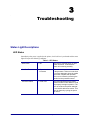
3 • Troubleshooting . . . . . . . . . . . . . . . . . . . . . . . . . . . . . . . . . . . . . . . . . . . . . . . 19
Status Light Descriptions . . . . . . . . . . . . . . . . . . . . . . . . . . . . . . . . . . . . . . . . . . . . . . . . .
LED States . . . . . . . . . . . . . . . . . . . . . . . . . . . . . . . . . . . . . . . . . . . . . . . . . . . . . . . . .
Status Indicator . . . . . . . . . . . . . . . . . . . . . . . . . . . . . . . . . . . . . . . . . . . . . . . . . . . . .
Print Quality Problems . . . . . . . . . . . . . . . . . . . . . . . . . . . . . . . . . . . . . . . . . . . . . . . . . . .
Media Sensing Problems . . . . . . . . . . . . . . . . . . . . . . . . . . . . . . . . . . . . . . . . . . . . . . . . .
Black Mark Calibration Process . . . . . . . . . . . . . . . . . . . . . . . . . . . . . . . . . . . . . . . . .
Other Problems . . . . . . . . . . . . . . . . . . . . . . . . . . . . . . . . . . . . . . . . . . . . . . . . . . . . . . . .
Contact Technical Support . . . . . . . . . . . . . . . . . . . . . . . . . . . . . . . . . . . . . . . . . . . . . . . .
P1055866-001
TTP 2030™ Technical Manual
19
19
21
21
23
23
25
26
04/14/2013
1
Introduction
Who Should Use This Document
This guide is intended for use by any person who needs to setup the TTP 2030 printer for use
with a Windows CE device.
How This Document Is Organized
The manual is set up as follows:
Introduction
Contact information, document conventions.
Windows CE Driver
Installation, updates, preferences, and properties.
Troubleshooting
Status light description, user interface, error handling,
and fixes to common printing problems.
This manual will be updated from time to time as printer functions and features may be added
or amended. You will always find the latest edition on our website at www.zebra.com.
If you require information for functions not found in this manual edition, please contact
Technical Support for your region or the Zebra partner the printer was purchased from.
Document Conventions
The following conventions are used in this document to convey certain information.
Alternate Color – Cross-references contain links to other sections in this guide. If you are
viewing this guide online, click the blue text to jump to its location.
Indicates information that emphasizes or supplements important points of the main text.
4/14/2013
TTP 2030™ Windows CE Software Integrator Guide
P1055866-001
2
Introduction
Document Conventions
P1055866-001
TTP 2030™ Windows CE Software Integrator Guide
4/14/2013
2
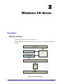
Windows CE Driver
Description
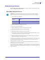
Windows CE Driver
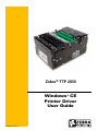
The following description applies to CE 6 and EC 7.
The illustration shows the relationship between the various system components involved in
printing.
APPLICATION
DISPLAY DRIVER
GDI
PRINTER DRIVER
PORT MONITOR
USB
PORT
PRINTER
Figure 1 • System Flowchart
4/14/2013
TTP 2030™ Windows CE Software Integrator Guide
P1055866-001
4
Windows CE Driver
Description
Printer Driver
The printer driver for the TTP 2030 is named TTP2000.DLL. The Windows CE graphics
device interface (GDI) and display driver perform most of the work involved in printing. At
the beginning of the printing process, GDI creates a device context with attributes that are
retrieved from the printer driver during a call to DrvEnablePDEV. The display driver, not the
printer driver, is used to render subsequent drawing commands that are issued from the
application into the device context. Therefore, some drawing functions that are present in a
printer driver, such as DrvStrokePath, are never called because the printer driver only renders
the document internally.
The printer driver converts the bitmap data from a GDI bitmap format into the format that is
recognized by the printer. This can include such operations as color reduction to the color
space of the printer, data compression, and data conversion into the format that is used by the
printer – a format sometimes known as a page-description language (PDL). Then, the printer
driver calls the port monitor to send the rendered image to the printer.
Only a small number of the graphics driver functions defined for printer drivers are required in
printer drivers for Windows CE. Printer drivers are required to implement only those graphics
driver functions that are necessary for gathering printer metrics, setting up the printer, starting
and ending print jobs, and preparing content for printing.
The following table shows the functions implemented in the driver:
Table 1 • Driver Functions
Function
P1055866-001
Description
DrvCopyBits
Translates between device-managed raster surfaces and
graphics device interface (GDI) standard format bitmaps.
DrvDisablePDEV
Used by MGDI to notify a driver that the specified PDEV
structure is no longer needed.
DrvDisableSurface
Used by the GDI to notify a driver that the surface created
by the DrvEnableSurface function for the current device
is no longer needed.
DrvEnableDriver
Specifies the initial driver entry point exported by the
driver DLL for devices that link directly to GWES, such
as display drivers and printer drivers. It fills a
DRVENABLEDATA structure with the driver version
number and calling addresses of functions supported by
the driver.
DrvEnablePDEV
Enables a device context for drawing and returns device
metrics for the target printer or display device in a
GDIINFO structure. Printer drivers call a display driver's
DrvEnablePDEV function to create and initialize the
device context, and then substitute the printer's device
metrics before returning the device context to the GDI for
bitmap rendering.
DrvEnableSurface
Sets up a surface to be drawn on and associates it with a
specified PDEV.
DrvEndDoc
Called by the GDI to finish or abort a print job.
TTP 2030™ Windows CE Software Integrator Guide
4/14/2013
Windows CE Driver
Description
Table 1 • Driver Functions
Function
Description
DrvGetModes
Lists the modes supported by a specified device.
DrvStartDoc
Called by the GDI to start a print job.
DrvStartPage
Called by the GDI to start printing the next page of a print
job.
GetPrinterInfo
Obtains information about printers, such as the name of
the printer or whether the printer can print in color.
PrinterClose
Closes a printer handle previously opened by a call to the
PrinterOpen function.
PrinterOpen
Opens a specified printer port and returns a handle to the
printer.
PrinterSend
Sends a block of data to a printer.
ReportPrinterStatus
Returns the status of a printer or printing operation that is
in progress.
GetPrinterStatus
Returns a specific TTP 2030 status.
Port Monitor
The port monitor for the TTP 2030 is called TTPPort.DLL. Printing is supported over
universal serial bus (USB) port only. The printing architecture provides application
programming interfaces (APIs) that are exposed by the Graphics, Windowing, and Events
Subsystem (GWES) to communicate with the printer driver. The printer driver communicates
with the port driver that sends the print data over the supported bus. Therefore, the printer
driver is independent of the bus and the corresponding bus driver.
Print Spooling
No separate printer spooler component exists in Windows CE, unlike the desktop versions of
the Windows OS. With Windows CE, spooling or background printing is implemented in the
printer driver itself. However, because print spooling typically consumes a lot of memory,
limited memory might be a problem. A practical print spooler usually has to implement a
complicated compression scheme to store spooled documents before printing.
Status Monitoring
In order to allow applications to get status from the printer, there are two functions
implemented:
• ReportPrinterStatus – the default function described in the MSDN documentation.
• GetPrinterStatus – the function that returns the actual printer status (described below).
4/14/2013
TTP 2030™ Windows CE Software Integrator Guide
P1055866-001
5
6
Windows CE Driver
Description
GetPrinterStatus
This function gets the specific Printer status for the TTP 2030.
Syntax DWORD WINAPI GetPrinterStatus(HANDLE hPrinter,
LPPRINTERSTATUS status)
Parm
hPrinter - HANDLE
- Handle to the printer
status - LPPRINTERSTATUS - The status to be set.
Return DWORD - Returns
ERROR_SUCCESS if everything went Ok, else :
ERROR_UNKNOWN_PORT
- If hPrinter is INVALID_HANDLE_VALUE
ERROR_READ_FAULT
- If read fail
ERROR_WRITE_FAULT
- If write fail
ERROR_NOT_SUPPORTED - If hPrinter is not supported
TTP 2030 Status codes
The following table shows all status codes that can be reported by the TTP 2030 printer from
the application.
Table 2 • Status Codes
P1055866-001
Status
code
Meaning
ACK
OK (printer is operable).
NAK 1
Paper left in presenter module. Attempt to clear the paper path failed.
NAK 2
Cutter jammed.
NAK 3
Out of paper.
NAK 4
Printhead lifted.
NAK 5
Paper-feed error. No paper detected in presenter although 10 cm has been printed.
Paper might be wound around the platen or, in some way, has been forced above the
presenter module.
NAK 6
Temperature error. The printhead temperature has exceeded the 60 °C maximum
limit.
NAK 7
Presenter not running.
NAK 8
Paper jam during retract.
NAK 0A
Black mark not found.
NAK 0B
Black mark calibration error.
NAK 0C
Index error.
NAK 0D
Checksum error.
NAK 0E
Wrong firmware type or target for firmware loading.
TTP 2030™ Windows CE Software Integrator Guide
4/14/2013
Windows CE Driver
Description
Table 2 • Status Codes
NAK 0F
Firmware cannot start because no firmware is loaded or firmware checksum is
wrong.
NAK 10
Retract function timed out. If the customer doesn’t take the paper and the printer
clears the presenter due to a timeout, the pending error bit is set and error code NAK
10h is reported.
Types of Status Monitoring
In order to incorporate the way status monitoring works for the TTP 2030 printer setup, it is
important to understand what happens in a kiosk when you print, and when status monitoring
should take place.
Status monitoring can be handled in two ways:
• Monitoring in the printing application
• Monitoring in a separate application
When monitoring takes place in the printing application, normally the printer is observed
before sending a print job to see if the printer is ‘OK’ and then send the print job. After the
print job is signaled as being printed, the status is checked again to see if the printer has any
errors or if the paper has been taken, etc.
Monitoring in a separate application usually doesn't allow direct interaction with the printed
job so the printer is polled as often as possible to get most accurate information on what the
printer is doing. This is usually very time consuming and care must be taken to achieve
synchronization and control over the current print job.
Monitoring While Printing
Status monitoring has been implemented in the internal printing structure of the driver. When a
document is opened, printed, and closed, the driver will check the printer status before and
after printing and will also react to write errors if any occur. It will then set the printer status
and raise the error event.
4/14/2013
TTP 2030™ Windows CE Software Integrator Guide
P1055866-001
7
8
Windows CE Driver
Description
Monitoring While Idle
In order to get status any time a status thread has to be implemented which reads printer status
and provides changed status information in the same manner. The following code snippet in
C# may be used as a guide to develop such an application. The code is using the
TTPConfig DLL.
TTPConfig config = new TTPConfig();
config.Load();//Load settings from registry
string msg = "";
try
{
config.open("LPT1:");
//getStatus is not synchronized with other read/write
functions
byte status = config.getStatus();
msg = "Status : " + status;
config.close("LPT1:");
}
catch (Exception ex)
{
msg = ex.Message;
MessageBox.Show("Status : " + msg);
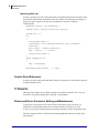
Control Panel Extension
In order to open the control panel and double click the program icon, a control panel extension
is supplied with the driver.
TTP2000CPL
This component enables users to change settings for the printer and printer driver. You can
access the Control Panel through Start > Settings > Control Panel.
Printer and Driver Parameter Setting and Maintenance
To provide an easy interface to set printer and driver parameters on the CE device, an
application is provided that handles device settings, and offers a Tools tab (see Tools
on page 16) to perform certain maintenance functions and print a printer configuration sheet.
The driver settings are done via the TTP 2030 Settings application that can be found in the
Control Panel.
P1055866-001
TTP 2030™ Windows CE Software Integrator Guide
4/14/2013
Windows CE Driver
Installation
Installation
CE Driver Installation
The Zebra CE driver ZIP package includes the following files:
• TTP2000CPL.CPL – The Control Panel that enables users to change settings for the
printer and printer driver
• TTP2000.DLL – the Printer Driver
• TTPPort.DLL – the Port Monitor
• TTPErr.DLL – the error handler
• TTP2030.CPY – a sample copy file
• TTPDevice.EXE – the Parameter setup application
• TTPConfig.DLL – a helper DLL for the parameter setup application
• FWDownload.EXE – the firmware update application
Extract the Zebra CE driver files for the TTP 2030 from the ZIP file and deploy the driver files
(TTP2000, TTPPort, TTPErr and TTP2000CPL) to the Windows directory. The sample copy
file (TTP2030.CPY) is included as a template for writing a copy file. This file is used during
each restart to copy files from permanent storage to their respective directories.
Firmware Update
UI Option
Check the firmware version installed on the printer by printing a configuration label (see Tools
on page 16), the firmware version will be shown.
To update the firmware
1. Go to the Zebra Website at www.zebra.com and follow the instructions to download the
latest version to your computer.
2. Copy the firmware package to the device to which the printer is connected and that runs
the driver.
3. Select the port that the target printer is connected to and then click Select FW.
4. Navigate to the firmware file and click Download Firmware.
5. To confirm the installation, click Yes.
The status light on the printer flashes intermittently between green and red indicating that
a firmware update is in progress. The printer resets when it has finished the upload.
4/14/2013
TTP 2030™ Windows CE Software Integrator Guide
P1055866-001
9
10
Windows CE Driver
Firmware Update
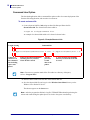
Command Line Option
The download application offers a command line option to allow for remote deployment of the
firmware file and application, and execution via a shortcut.
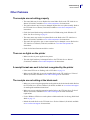
To create a shortcut file
1. Create a shortcut link file (.lnk) using an editor like Notepad. Name the file
ShortCutTest.lnk. The format for the shortcut link is:
<length of string>#<command line>
An example of a shortcut link and how it is formed is shown below.
Figure 2 • Example Shortcut Link
Command line
Length of string
75#\Application\Zebra\FWDownload.exe /P LPT1: /F \Application\Zebra\V1819.3.86
Number of
characters in
the command
line including
spaces and
quotes
Firmware download application
including directory location
where the file is stored
/P is the
port used
to send
data to the
printer
/F is the firmware file including
directory location where the file
is stored
Note • You must use quotation marks if the file resides in a directory with spaces,
such as “\Program Files”.
2. Place the shortcut link on the first line of the shortcut link file.
3. Save the shortcut link file, and copy it to the \Windows\Start Menu directory on the
Windows CE or Pocket PC device.
The shortcut appears on the Start menu.
Note • After the program has finished, a log file (TTP2030FWDownload.log) showing the
actions and results during the update process is saved to the system root directory.
P1055866-001
TTP 2030™ Windows CE Software Integrator Guide
4/14/2013
Windows CE Driver
Printer Settings
Printer Settings
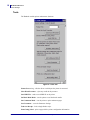
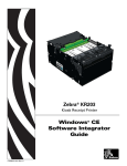
Device Settings
The TTP 2030 Settings dialog box controls the printer and driver settings.
Figure 3 • Device Settings Tab
The following table describes the values and defaults of the parameters:
Table 3 • Parameter Settings and Defaults
Parameter
4/14/2013
Value Range
Default Value
Media Width
58 mm, 60 mm, 80 mm,
82.5 mm
80 mm
Media Height
90 mm to 600 mm
150 mm
Darkness
1 to 15
9
Max Print Speed (mm/s)
47 mm to 150 mm
150 mm
TTP 2030™ Windows CE Software Integrator Guide
P1055866-001
11
12
Windows CE Driver
Printer Settings
Table 3 • Parameter Settings and Defaults
Parameter
Value Range
Default Value
Media Tracking
Continuous, Variable Length,
Mark Sensing
Variable Length
Top Margin (mm)
2 mm to 10 mm
10 mm
Bottom Margin (mm)
0 to 9 mm
0
Cutter Mode
None, Every Page, End of
Document
Every Page
Partial Cut Width
0, 10 mm to 60 mm
0
Presenter Loop Length
0 to 600 mm
416 mm
Eject Length
20 mm to 600 mm
50 mm
Present Length Addition
0 to 255 mm
0
Presenter Timeout
0 to 300 seconds
0
Clear Presenter
Disable, Enable
Disable
Presenter Mode
Eject, Retract
Eject
• OK – applies the settings and exits the program
• Cancel – does not apply the settings and exits the program
• Apply – applies the settings but does not exit the program
• Default – sets all settings to factory default
The following parameter settings are sent to the printer during each print job.
Media Width
The media width can be set to 58 mm, 60 mm, 80 mm and 82.5 mm. The default setting is
80 mm.
Media Height
The media height can be set between the minimum page length of 90 mm and the maximum
page length of 600 mm. The default setting is 150 mm.
Darkness
The Darkness can be set between 1 and 15 with 1 being the lightest. The default setting
is 9.
Max Print Speed
The max print speed can be set between 47 mm and 150 mm per second (mm/s). The default
setting is 150 mm/s. The actual print speed may vary depending on the darkness and the
content printed.
P1055866-001
TTP 2030™ Windows CE Software Integrator Guide
4/14/2013
Windows CE Driver
Printer Settings
Media Tracking
Media Tracking sets Continuous, Variable Length, or Mark Sensing with the default set to
Variable Length. When media tracking is set to Continuous, the driver sends the full page size
to the printer (Page Mode), the page length will always be the same as the selected paper size
(e.g., if 58 mm x 200 mm Media is selected, the print will be 200 mm long in Page Mode).
When media tracking is set to Variable Length, the driver will shorten the length of the page to
the length of the printed element. The driver will end the page after the last printed element
(text, barcode, or graphic) then send a feed, cut, and eject command. The page length may vary
from page to page but will always be a minimum of 76 mm. When Mark Sensing is set, the
driver will send the page size to the printer, the printer will restrict the print to the area between
the black marks. If the printed area is larger than the space between the black marks, it will
print additional pages (receipts). The margin values in the receipt application must be
corrected after setting the driver values. If the margin in the application is set to 9 mm and the
driver is set to 2 mm, the application setting will be enforced unless the driver is changed
accordingly.
Top Margin
The Top Margin is the equivalent to the distance between the cutter and the print head and is
by default 10 mm. If it is set between the minimum of 2 mm or 10 mm it will reverse the paper.
Bottom Margin
The Bottom margin can be set between 0 and 9 mm and will be added to the bottom of the
page in Variable Mode and will limit the printable area in Continuous Mode and Mark Sensing.
The default is 0.
Cutter Mode
Cutter Mode can be set to None, Every Page and Cut at the document end. The default is Every
Page. When set to Every Page and a multi-page document is printed each page will be cut. If
set to Cut at document end and a multi-page document is printed all pages will print and only
one cut at the end of the document will be issued. Partial Cut Width is used with Cut at
document end.
4/14/2013
TTP 2030™ Windows CE Software Integrator Guide
P1055866-001
13
14
Windows CE Driver
Printer Settings
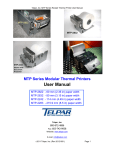
Partial Cut Width
Partial cut leaves multi-page receipts attached at the specified width. The partial cut width can
be set to 0 and between 10 and 60 mm; the default is 0 and it disables partial cut (full cut).
Partial cut can only be used with the Cut at document end selection in Cutter Mode.
Page 1
Page 1
10 mm
60 mm
Page 2
Page 2
Cut
Not Cut
Figure 4 • Partial Cut Diagram
Presenter Loop Length
Presenter Loop Length determines how much paper is held in the presenter loop. The presenter
loop length can be set between 0 and 600 mm and the default value is 416 mm. A setting of 0
disables the presenter loop and media feed directly through the presenter.
Eject Length
Eject Length determines how much paper is exposed for the customer. The range is from
20mm to 600mm with the default set to 50mm. If the eject length is set larger than the length
of the receipt, the printer will retain a portion of the receipt in the presenter unless the “Clear
Presenter” option is set to “Enable”.
Present Length Addition
Presenter Length Addition is an additional length to compensate for the thickness of the kiosk
wall. The range is from 0 to 255 mm with the default set to 0.
Presenter Timeout
Presenter Timeout determines how long the presenter will hold the receipt before ejecting it.
The range for the timeout is from 0 to 300 seconds with the default set at 0.
Note • Presenter timeout value must have a minimum of 10 seconds in order to work
properly.
P1055866-001
TTP 2030™ Windows CE Software Integrator Guide
4/14/2013
Windows CE Driver
Printer Settings
Clear Presenter
Clear Presenter determines if a receipt is retained, or if it is ejected from the presenter after the
timeout.
Presenter Mode
The Presenter Mode determines if a receipt will be ejected or retracted when a new receipt
enters the presenter. In either case, the receipt will be retracted if the timeout occurs.
4/14/2013
TTP 2030™ Windows CE Software Integrator Guide
P1055866-001
15
16
Windows CE Driver
Printer Settings
Tools
The Tools tab enables printer maintenance functions.
Figure 5 • Tools Tab
Printer Port setting – tells the driver to which port the printer is connected
Clear Kiosk Presenter – ejects any media in the presenter
Send PRN File – sends a saved PRN file to the printer
Set Black Mark Mode – sets the printer to use black mark media
Set Continuous Mode – sets the printer to print continuous pages
Save Parameter – saves the Parameter Settings
Feed One Receipt – feeds a single blank receipt
Print Config Label – prints a page with the printer configuration information
P1055866-001
TTP 2030™ Windows CE Software Integrator Guide
4/14/2013
Windows CE Driver
Printer Settings
About
The About tab shows the current driver version.
Figure 6 • About Tab
4/14/2013
TTP 2030™ Windows CE Software Integrator Guide
P1055866-001
17
18
Windows CE Driver
Setting Black Mark Mode
Setting Black Mark Mode
The printer is optimized to detect black marks printed with IR sensitive ink and ignore preprint
in IR blind ink as follows:
• 80 and 82.5 mm media – the black marks are centered 30 mm to the right of the paper
center when viewing the imaged side of the receipt and print direction is downward
• 58 and 60 mm media – the black marks are centered 22 mm to the left of the paper when
viewing the imaged side of the receipt and the print direction is downward
The printer supports media with black mark thickness in printing direction of 2.5-9.0 mm, and
a width of 5.0-10.0 mm when the black mark is centered on the sensor.
Refer to the TTP 2000 Series Technical Manual (P1002902) available at
www.zebra.com/support for black mark media requirements and media guide installation
instructions.
To set black mark mode:
1. Choose the correct media guide for the desired media width.
2. Load the desired media.
3. In the Tools tab of the Windows driver, click Set Black Mark Mode.
A dialog box appears asking you to confirm your selection.
4. Click Yes.
The printer feeds the media, detects the black marks, and ejects the media.
5. Press the Feed button on the printer several times to confirm the printer is cutting directly
in the center of the black marks.
6. In the Device Settings tab of the Windows driver, set the Media Tracking to
Mark Sensing.
Note • If you revert back to Continuous mode, set the Media Tracking back to Continuous
or Variable.
P1055866-001
TTP 2030™ Windows CE Software Integrator Guide
4/14/2013
3
Troubleshooting
Status Light Descriptions
LED States
Immediately after power is applied to the printer, a brief self test is performed and the status
light will report the following conditions:
Table 1 • LED States
4/14/2013
Solid Green
0 - OK
This code is reported when no other
codes are active. It indicates the
printer is functioning normally.
One Red Flash
1 - Paper Jam in
Presenter
This code indicates that media is stuck
in the presenter. This error is set when
the printer attempts to eject the media
but cannot complete the operation.
This error is cleared by removing the
media from the presenter sensor.
Two Red Flashes
2 - Cutter Jam
This code indicates that the printer
could not find the cutter blade or could
not properly manage its position. The
error is set when the printer attempts
to cut but fails after three retries. This
error is cleared by cycling the power
off and on.
TTP 2030™ Windows CE Software Integrator Guide
P1055866-001
20
Troubleshooting
Status Light Descriptions
Table 1 • LED States
P1055866-001
Three Red Flashes
3 - Out of Paper
This code indicates that the selected
EOP sensor has detected no media
present. This value is signaled when
the mark engine has detected a mark
larger than "TOF marker length” plus
5mm, or when the A/D reading of the
EOP sensor drops below the “End of
paper threshold”. This error is cleared
after successful media load (either via
calibration or via regular media load).
Four Red Flashes
4 - Print Head Lifted
This code indicates that the print head
has been lifted. This error is cleared
by returning the print head to its
locked position.
Five Red Flashes
5 - Paper Feed Error
This code indicates that the paper
failed to reach the presenter sensor
within the expected amount of time.
The error is signaled if the media does
not reach the presenter sensor after
feeding the length from the cutter to
the sensor plus 15mm. This error is
cleared by opening and closing the
print head, or by cycling power off and
on.
Yellow Flashing
6 - Head Temperature
Error
This code indicates that the print head
has exceeded the maximum permitted
temperature. This status code is set
when the print head temperature
exceeds 65° C (149° F). When this
condition occurs, the printer feeds
100mm (4 inches) of blank media,
cuts, and presents. This error is
cleared automatically when the print
head temperature falls below 55° C
(131° F).
Rapid Amber
Flashing
Firmware missing or
corrupt
This code indicates that the bootware
has detected an incorrect or missing
checksum in the firmware. This error is
cleared when the firmware is reloaded
or updated. Refer to the TTP 2000
Series Technical Manual for firmware
upload procedure.
TTP 2030™ Windows CE Software Integrator Guide
4/14/2013
Troubleshooting
Print Quality Problems
Status Indicator
The orange status indicator has several functions:
• ON constantly – the printer is operational
• Flash, flash, pause, flash, flash – is the warning-code for paper low. The warning-code is
reset automatically when the condition causing it is removed. This behavior can be
enabled by setting parameter 52 (Warning Level) to 001.
• Flashes rapidly – indicates error. Press and hold the Feed button and the number of flashes
will reflect the status-code.
1
Presenter jam, paper cannot be ejected / retracted
2
Cutter cannot return to home position
3
Out of paper
4
Printhead lifted
5
Paper feed error (under head)
6
Temp error, printhead is above 60°C
7
Paper jam during present
8
Paper jam during retract
10
Black mark not found (on media load)
11
Black mark calibration error
Fast flashes Checksum error at firmware loading
Steady light Wrong firmware type
Status codes are reset when the:
• Conditions causing them are removed
• Printer is power cycled (turned off/on)
• Printhead is lifted and then lowered to clear a paper jam
Print Quality Problems
No print on the label
• The media may not be direct thermal media.
• Is the media loaded correctly? Is the thermal media coating facing upward?
• The printhead may be dirty or damaged.
• The printhead is dirty. Clean the printhead. Refer to the TTP 2000 Service Manual
(P1002903) available at www.zebra.com/partners for instructions.
• The printhead is damaged. Replace the printhead. Refer to the TTP 2000 Service Manual
(P1002903) available at www.zebra.com/partners for instructions.
4/14/2013
TTP 2030™ Windows CE Software Integrator Guide
P1055866-001
21
22
Troubleshooting
Print Quality Problems
• The printhead cable may be damaged or not connected properly.
•
Check the cable connections at the printhead and the main logic board.
•
Check for damage to the cable. Replace the cable if damaged.
The printed image does not look right
• The printhead is dirty. Clean the printhead. Refer to the TTP 2000 Service Manual
(P1002903) available at www.zebra.com/partners for instructions.
• The printhead has worn out. The printhead is a consumable item and will wear out due to
friction between the media and printhead. Using unapproved media may shorten life or
damage your printhead. Replace the printhead. Refer to the TTP 2000 Service Manual
(P1002903) available at www.zebra.com/partners for instructions.
• Adjust the print darkness and/or print speed. See Device Settings on page 11.
•
The Windows printer driver or application software can change these settings and
may require a change to optimize print quality.
• The media being used is incompatible with the printer. Be sure to use the recommended
media for your application, and always use Zebra-approved media.
• The platen (driver) roller may be losing traction due to foreign objects attached to its
surface or the rubbery smooth surface may have become polished and slippery.
•
The platen may need cleaning or replacement. Refer to the TTP 2000 Service Manual
(P1002903) available at www.zebra.com/partners for instructions.
There are long tracks of missing print (blank vertical lines) on
several labels
• The printhead may be dirty or damaged.
•
The printhead is dirty. Clean the printhead. Refer to the TTP 2000 Service Manual
(P1002903) available at www.zebra.com/partners for instructions.
•
The printhead is damaged. Replace the printhead. Refer to the TTP 2000 Service
Manual (P1002903) available at www.zebra.com/partners for instructions.
• The printhead has worn out. The printhead is a consumable item and will wear out due to
friction between the media and printhead. Using unapproved media may shorten life or
damage your printhead. Replace the printhead. Refer to the TTP 2000 Service Manual
(P1002903) available at www.zebra.com/partners for instructions.
The printing does not start at the top of the receipt or misprinting of
one to three receipts
• Reload the media. Refer to the TTP 2000 Service Manual (P1002903) available at
www.zebra.com/partners for instructions.
P1055866-001
TTP 2030™ Windows CE Software Integrator Guide
4/14/2013
Troubleshooting
Media Sensing Problems
Media Sensing Problems
The TTP 2030™ printer default media mode is Variable. The printer will remain in this mode
until it is changed by the Windows Driver.
Black Mark Calibration Process
Important • In variable and fixed page mode, only the paper out level will be calibrated
while in black mark mode all parameters affecting black mark detection will be calibrated.
1. Prepare the printer for calibration:
If your Firmware is
version…
Then…
3.54 or higher
Set Parameter 35 (Black Mark Mode) to a value of 1
3.50 or lower
Set Parameter 36 (Document Mode) to a value of 2
2. Open the printhead by pushing the lever on top.
3. Remove the paper from the printer.
4. With the printhead open, hold the Feed button for five seconds.
5. While still holding the Feed button, close the printhead.
6. When the Status light goes off, let go of the Feed button.
7. Insert the paper. The printer performs a calibration and stops. If the status light is on and
not flashing after calibration, the calibration is successful.
8. Open the printhead, remove the paper, then close the printhead and insert the paper into
the printer. The printer is now ready to be used.
To confirm that the calibration was successful, press the Feed button once. If the printer feeds
and cuts at the correct position, the printer is calibrated correctly. If the printer cuts at the
incorrect position, repeat steps 1-7 above.
To fine tune the cut, modify the value of parameter 46 (Black Mark Sensor Calibration) or
change the Cut position value in the driver.
If the printer does not detect blacklines (or notches with black mark sensing) after feeding the
media the default maximum label length distance of 24 inches (610 mm), then the printer will
report a media error.
4/14/2013
TTP 2030™ Windows CE Software Integrator Guide
P1055866-001
23
24
Troubleshooting
Media Sensing Problems
The printer will not load the media
• The leading edge of the media is not cut straight, so the media sensor does not see the
media to auto-feed it. Cut the paper at 90 degree angle to the sides and try again.
• The media has changed or a different media guide has been installed.
•
Make sure the appropriate media guide is installed for the media being used. Refer to
the TTP 2000 Series Technical Manual (P1002902) available at
www.zebra.com/support for instructions.
•
Load the media manually. Refer to the TTP 2000 Series Technical Manual
(P1002902) available at www.zebra.com/support for instructions.
• The platen (driver) roller may be losing traction due to foreign objects attached to its
surface or the rubbery smooth surface may have become polished and slippery.
•
The platen may need cleaning or replacement. Refer to the TTP 2000 Service Manual
(P1002903) available at www.zebra.com/partners for instructions.
• The media sensor may be dirty or damaged. Refer to the TTP 2000 Service Manual
(P1002903) available at www.zebra.com/partners for instructions.
• The printhead assembly is not closed.
•
Check the status light on either side of the printer. If the status light is showing four
red flashes then the printhead is not closed. Push down on the printhead assembly
until it locks into place.
• There is a paper jam under the printhead. Refer to the TTP 2000 Series Technical Manual
(P1002902) available at www.zebra.com/support for instructions.
• The large media roll may be over torquing the feed motor. Install the large media roll
adapter. Refer to the TTP 2000 Series Technical Manual (P1002902) available at
www.zebra.com/support for instructions.
The printer will not eject the media
• The presenter rollers are dirty or damaged. Refer to the TTP 2000 Service Manual
(P1002903) available at www.zebra.com/partners for instructions.
• There is a jam under the presenter. Refer to the TTP 2000 Service Manual (P1002903)
available at www.zebra.com/partners for instructions.
• The presenter sensor may be dirty or damaged. Refer to the TTP 2000 Service Manual
(P1002903) available at www.zebra.com/partners for instructions.
• The presenter has not cleared the previous receipt.
•
Check the status light on either side of the printer. If the status light is showing one
flash, then the printer is reporting media in the presenter. Remove any media that may
be in the presenter.
• The presenter motor may need to be replaced. Refer to the TTP 2000 Service Manual
(P1002903) available at www.zebra.com/partners for instructions.
• The presenter drive gears may be damaged or worn. Refer to the TTP 2000 Service
Manual (P1002903) available at www.zebra.com/partners for instructions.
P1055866-001
TTP 2030™ Windows CE Software Integrator Guide
4/14/2013
Troubleshooting
Other Problems
Other Problems
The receipts are not cutting properly
• The cutter blade may be worn. Replace the cutter blades. Refer to the TTP 2000 Service
Manual (P1002903) available at www.zebra.com/partners for instructions.
• The cutter tensioner may be worn or damaged. Replace the cover plate assembly. Refer to
the TTP 2000 Service Manual (P1002903) available at www.zebra.com/partners for
instructions.
• Check the Cutter Mode setting, and the Partial Cut Width setting in the Windows CE
driver. See Device Settings on page 11.
• The cutter motor may need to be replaced. Refer to the Refer to the TTP 2000 Service
Manual (P1002903) available at www.zebra.com/partners for instructions.
• The cutter drive gear, drive pin, or cutter actuator may be damaged or worn. Refer to the
TTP 2000 Service Manual (P1002903) available at www.zebra.com/partners for
instructions.
• Check for the latest firmware and driver version.
There are no lights on the printer
• Make sure there is power applied to the printer.
• The main logic board may be damaged. Refer to the TTP 2000 Service Manual
(P1002903) available at www.zebra.com/partners for instructions.
A receipt format was sent to but not recognized by the printer
• If the status LED is on or flashing, refer to LED States on page 19.
• Make sure the USB cable is correctly installed. Refer to the TTP 2000 Series Technical
Manual (P1002902) available at www.zebra.com/support for instructions.
The receipts are not cutting at the black mark
• Make sure you are using the appropriate media guide for the desired media width. Refer to
the TTP 2000 Series Technical Manual (P1002902) available at www.zebra.com/support
for media guide installation instructions.
• Make sure you are using the appropriate media. Refer to the TTP 2000 Series Technical
Manual (P1002902) available at www.zebra.com/support for black mark media
requirements.
• Use the Windows CE driver to set the printer to black mark mode. See Setting Black Mark
Mode on page 18.
• Reload the media. Refer to the TTP 2000 Series Technical Manual (P1002902) available
at www.zebra.com/support for instructions.
4/14/2013
TTP 2030™ Windows CE Software Integrator Guide
P1055866-001
25
26
Troubleshooting
Contact Technical Support
Contact Technical Support
Technical Support via the Internet is available 24 hours per day, 365 days per year at
www.zebra.com.
For questions on the operation of Zebra equipment and software, please call your distributor.
For additional assistance, contact us.
Please have your model and serial numbers available.
P1055866-001
TTP 2030™ Windows CE Software Integrator Guide
4/14/2013