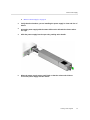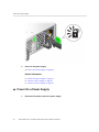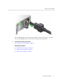
1
Oracle Switch ES2-72 and Oracle Switch
ES2-64 Service Manual
®
Part No: E60187-01
April 2015
Part No: E60187-01
Copyright © 2015, Oracle and/or its affiliates. All rights reserved.
This software and related documentation are provided under a license agreement containing restrictions on use and disclosure and are protected by intellectual property laws. Except
as expressly permitted in your license agreement or allowed by law, you may not use, copy, reproduce, translate, broadcast, modify, license, transmit, distribute, exhibit, perform,
publish, or display any part, in any form, or by any means. Reverse engineering, disassembly, or decompilation of this software, unless required by law for interoperability, is
prohibited.
The information contained herein is subject to change without notice and is not warranted to be error-free. If you find any errors, please report them to us in writing.
If this is software or related documentation that is delivered to the U.S. Government or anyone licensing it on behalf of the U.S. Government, then the following notice is applicable:
U.S. GOVERNMENT END USERS. Oracle programs, including any operating system, integrated software, any programs installed on the hardware, and/or documentation, delivered
to U.S. Government end users are "commercial computer software" pursuant to the applicable Federal Acquisition Regulation and agency-specific supplemental regulations. As
such, use, duplication, disclosure, modification, and adaptation of the programs, including any operating system, integrated software, any programs installed on the hardware, and/or
documentation, shall be subject to license terms and license restrictions applicable to the programs. No other rights are granted to the U.S. Government.
This software or hardware is developed for general use in a variety of information management applications. It is not developed or intended for use in any inherently dangerous
applications, including applications that may create a risk of personal injury. If you use this software or hardware in dangerous applications, then you shall be responsible to take all
appropriate fail-safe, backup, redundancy, and other measures to ensure its safe use. Oracle Corporation and its affiliates disclaim any liability for any damages caused by use of this
software or hardware in dangerous applications.
Oracle and Java are registered trademarks of Oracle and/or its affiliates. Other names may be trademarks of their respective owners.
Intel and Intel Xeon are trademarks or registered trademarks of Intel Corporation. All SPARC trademarks are used under license and are trademarks or registered trademarks of
SPARC International, Inc. AMD, Opteron, the AMD logo, and the AMD Opteron logo are trademarks or registered trademarks of Advanced Micro Devices. UNIX is a registered
trademark of The Open Group.
This software or hardware and documentation may provide access to or information about content, products, and services from third parties. Oracle Corporation and its affiliates are
not responsible for and expressly disclaim all warranties of any kind with respect to third-party content, products, and services unless otherwise set forth in an applicable agreement
between you and Oracle. Oracle Corporation and its affiliates will not be responsible for any loss, costs, or damages incurred due to your access to or use of third-party content,
products, or services, except as set forth in an applicable agreement between you and Oracle.
Documentation Accessibility
For information about Oracle's commitment to accessibility, visit the Oracle Accessibility Program website at http://www.oracle.com/pls/topic/lookup?ctx=acc&id=docacc.
Access to Oracle Support
Oracle customers that have purchased support have access to electronic support through My Oracle Support. For information, visit http://www.oracle.com/pls/topic/lookup?
ctx=acc&id=info or visit http://www.oracle.com/pls/topic/lookup?ctx=acc&id=trs if you are hearing impaired.
Référence: E60187-01
Copyright © 2015, Oracle et/ou ses affiliés. Tous droits réservés.
Ce logiciel et la documentation qui l’accompagne sont protégés par les lois sur la propriété intellectuelle. Ils sont concédés sous licence et soumis à des restrictions d’utilisation et
de divulgation. Sauf stipulation expresse de votre contrat de licence ou de la loi, vous ne pouvez pas copier, reproduire, traduire, diffuser, modifier, breveter, transmettre, distribuer,
exposer, exécuter, publier ou afficher le logiciel, même partiellement, sous quelque forme et par quelque procédé que ce soit. Par ailleurs, il est interdit de procéder à toute ingénierie
inverse du logiciel, de le désassembler ou de le décompiler, excepté à des fins d’interopérabilité avec des logiciels tiers ou tel que prescrit par la loi.
Les informations fournies dans ce document sont susceptibles de modification sans préavis. Par ailleurs, Oracle Corporation ne garantit pas qu’elles soient exemptes d’erreurs et vous
invite, le cas échéant, à lui en faire part par écrit.
Si ce logiciel, ou la documentation qui l’accompagne, est concédé sous licence au Gouvernement des Etats-Unis, ou à toute entité qui délivre la licence de ce logiciel ou l’utilise pour
le compte du Gouvernement des Etats-Unis, la notice suivante s’applique:
U.S. GOVERNMENT END USERS. Oracle programs, including any operating system, integrated software, any programs installed on the hardware, and/or documentation, delivered
to U.S. Government end users are "commercial computer software" pursuant to the applicable Federal Acquisition Regulation and agency-specific supplemental regulations. As
such, use, duplication, disclosure, modification, and adaptation of the programs, including any operating system, integrated software, any programs installed on the hardware, and/or
documentation, shall be subject to license terms and license restrictions applicable to the programs. No other rights are granted to the U.S. Government.
Ce logiciel ou matériel a été développé pour un usage général dans le cadre d’applications de gestion des informations. Ce logiciel ou matériel n’est pas conçu ni n’est destiné
à être utilisé dans des applications à risque, notamment dans des applications pouvant causer des dommages corporels. Si vous utilisez ce logiciel ou matériel dans le cadre d’
applications dangereuses, il est de votre responsabilité de prendre toutes les mesures de secours, de sauvegarde, de redondance et autres mesures nécessaires à son utilisation dans des
conditions optimales de sécurité. Oracle Corporation et ses affiliés déclinent toute responsabilité quant aux dommages causés par l’utilisation de ce logiciel ou matériel pour ce type
d’applications.
Oracle et Java sont des marques déposées d’Oracle Corporation et/ou de ses affiliés. Tout autre nom mentionné peut correspondre à des marques appartenant à d’autres propriétaires
qu’Oracle.
Intel et Intel Xeon sont des marques ou des marques déposées d’Intel Corporation. Toutes les marques SPARC sont utilisées sous licence et sont des marques ou des marques
déposées de SPARC International, Inc. AMD, Opteron, le logo AMD et le logo AMD Opteron sont des marques ou des marques déposées d’Advanced Micro Devices. UNIX est une
marque déposée d’The Open Group.
Ce logiciel ou matériel et la documentation qui l’accompagne peuvent fournir des informations ou des liens donnant accès à des contenus, des produits et des services émanant de
tiers. Oracle Corporation et ses affiliés déclinent toute responsabilité ou garantie expresse quant aux contenus, produits ou services émanant de tiers, sauf mention contraire stipulée
dans un contrat entre vous et Oracle. En aucun cas, Oracle Corporation et ses affiliés ne sauraient être tenus pour responsables des pertes subies, des coûts occasionnés ou des
dommages causés par l’accès à des contenus, produits ou services tiers, ou à leur utilisation, sauf mention contraire stipulée dans un contrat entre vous et Oracle.
Accessibilité de la documentation
Pour plus d’informations sur l’engagement d’Oracle pour l’accessibilité à la documentation, visitez le site Web Oracle Accessibility Program, à l'adresse http://www.oracle.com/
pls/topic/lookup?ctx=acc&id=docacc.
Accès au support électronique
Les clients Oracle qui ont souscrit un contrat de support ont accès au support électronique via My Oracle Support. Pour plus d'informations, visitez le site http://www.oracle.com/
pls/topic/lookup?ctx=acc&id=info ou le site http://www.oracle.com/pls/topic/lookup?ctx=acc&id=trs si vous êtes malentendant.
Contents
Using This Documentation ................................................................................. 7
Detecting and Managing Faults .......................................................................... 9
Front Panel LEDs ........................................................................................... 9
Rear Panel LEDs ........................................................................................... 11
▼ Check Switch Status (LEDs) ...................................................................... 12
Sensors Overview .......................................................................................... 13
▼ Check Switch Status (Oracle ILOM) ........................................................... 13
Component Sensor Targets .............................................................................. 14
Motherboard Sensor Targets ............................................................................ 15
Preparing for Service ........................................................................................ 17
ESD Precautions ........................................................................................... 17
Tools Needed for Service ................................................................................ 18
Replaceable Components ................................................................................ 18
Servicing Power Supplies ................................................................................. 21
▼ Power Off a Power Supply ........................................................................ 21
▼ Remove a Power Supply ........................................................................... 22
▼ Install a Power Supply .............................................................................. 24
▼ Power On a Power Supply ......................................................................... 26
Servicing Fan Modules ..................................................................................... 29
▼ Remove a Fan Module .............................................................................. 29
▼ Install a Fan Module ................................................................................. 31
Servicing Data Cables ....................................................................................... 35
▼ Remove a Data Cable ............................................................................... 35
▼ Install a Data Cable .................................................................................. 37
5
Contents
Glossary ............................................................................................................ 45
Index .................................................................................................................. 47
6
Oracle Switch ES2-72 and Oracle Switch ES2-64 Service Manual • April 2015
Using This Documentation
■
■
■
Overview – Describes how to troubleshoot and maintain the Oracle Switch ES2-72 and
Oracle Switch ES2-64
Audience – Enterprise network and system administrators with experience installing
network hardware and software
Required knowledge – Advanced experience working with hardware and software
Product Documentation Library
Late-breaking information and known issues for this product are included in the documentation
library at http://www.oracle.com/goto/es2-72_es2-64/docs.
Feedback
Provide feedback about this documentation at http://www.oracle.com/goto/docfeedback.
Using This Documentation
7
8
Oracle Switch ES2-72 and Oracle Switch ES2-64 Service Manual • April 2015
Detecting and Managing Faults
These topics describe how to detect and manage faults.
■
■
■
■
■
■
■
“Front Panel LEDs” on page 9
“Rear Panel LEDs” on page 11
“Check Switch Status (LEDs)” on page 12
“Sensors Overview” on page 13
“Check Switch Status (Oracle ILOM)” on page 13
“Component Sensor Targets” on page 14
“Motherboard Sensor Targets” on page 15
Related Information
■
■
■
“Preparing for Service”
“Servicing Power Supplies”
“Servicing Fan Modules”
Front Panel LEDs
The network management status, link status, and switch status LEDs are located at the front of
the switch.
Detecting and Managing Faults
9
Front Panel LEDs
Note - The System Fault/Alarm (Yellow) and System OK (Green) LEDs cannot be on at the
same time.
No.
Name
Color
Description
1
Network Management Link and
Activity
Green
Link (left):
■ On – 10 or 100BASE-T link.
■ Off – No link or link down.
Activity (right):
■ Off – No activity.
■ Flashing – Packet activity.
2
Locate
White
Helps locate the switch:
■ Off – No locate command invoked.
■ Fast blink – Occurs one second after the locate command is invoked.
3
Attention
Yellow
Has two states:
■ Off – No fault.
■ On solid – A fault in the system is present and service action is required.
4
OK
Green
Has three states:
■ Slow blink – During startup and shutdown sequences.
■ On solid – System normal and operational.
■ Off – Power interruption or system fault. Note: The off state could be
triggered by one power supply being unplugged. The switch is still fully
10
Oracle Switch ES2-72 and Oracle Switch ES2-64 Service Manual • April 2015
Rear Panel LEDs
No.
Name
Color
Description
operational with only one power supply, but this LED is changed to the off
state when one power supply is unplugged or not functioning correctly.
5
Service Processor
6
QSFP+ port Ethernet Link Status/
Activity for 40GbE connection
Green
(Oracle Switch ES2-64 only)
Green
7
Has three states:
■ Off – No link or activity on the QSFP+ port.
■ On – A link has been established on the QSFP+ port.
■ Blinking – There is activity on the QSFP+ port.
10GBaseT port Ethernet Link
Status/Activity
Has three states:
■ Off – No link or activity on the port.
■ On – A link has been established on the port.
■ Blinking – There is activity on the port.
Related Information
■
■
“Rear Panel LEDs” on page 11
“Check Switch Status (LEDs)” on page 12
Rear Panel LEDs
The power supply and fan status LEDs are located at the front of the switch.
Detecting and Managing Faults
11
Check Switch Status (LEDs)
No.
Name
Color
State and Meaning
2
Power Supply OK
Green
On – Power supply is functional without fault.
3
Power Supply Attention
Yellow
Off – Power supply is off or initializing.
On – Fault detected, 12 VDC shut down.
Off – No faults detected.
4
Power Supply AC
Green
On – AC is functional without fault.
Off – AC is off or initializing.
1
Fan Module Attention
Yellow
On – Fan module has a fault.
Off – No faults detected.
Related Information
■
■
“Front Panel LEDs” on page 9
“Check Switch Status (LEDs)” on page 12
Check Switch Status (LEDs)
Check the LEDs to verify the switch status.
12
Oracle Switch ES2-72 and Oracle Switch ES2-64 Service Manual • April 2015
Sensors Overview
See “Front Panel LEDs” on page 9 and “Rear Panel LEDs” on page 11.
Related Information
■
“Check Switch Status (Oracle ILOM)” on page 13
Sensors Overview
The switch uses several configurable sensors and indicators to monitor switch power, voltage,
and temperature.
The switch includes a sensor for each replaceable component. These sensors generate entries in
the SEL when sensor thresholds are exceeded. Many of these readings are used to adjust the fan
speeds and perform other actions, such as illuminating LEDs and powering off the switch.
You can also configure these sensors to generate IPMI PET and SNMP traps, as described in the
Sun Integrated Lights Out Manager (ILOM) CLI Procedures Guide.
Caution - Do not use any interface other than the Oracle ILOM CLI or web interface to alter the
state or configuration of any sensor or LED. Doing so could void your warranty.
You can view the system monitoring sensors and indicator parameters from the Oracle ILOM
CLI or web interface.
Related Information
■
“Check Switch Status (Oracle ILOM)” on page 13
Check Switch Status (Oracle ILOM)
1.
Log into Oracle ILOM.
Refer to the Oracle Switch ES2-72 and Oracle Switch ES2-64 Installation Guide for
instructions.
2.
Display the status of parameters of switch components or the motherboard.
-> show target value
Detecting and Managing Faults
13
Component Sensor Targets
where target is the Oracle ILOM target name of the component or motherboard sensor in
“Component Sensor Targets” on page 14 or “Motherboard Sensor Targets” on page 15.
For example, to display the status of the fan 0 Attention LED, type.
-> show /SYS/FM0/SERVICE value
/SYS/FM0/SERVICE
Properties:
value = Off
Related Information
■
■
■
“Component Sensor Targets” on page 14
“Motherboard Sensor Targets” on page 15
“Check Switch Status (LEDs)” on page 12
Component Sensor Targets
Use the targets from this table to check the switch status. See “Check Switch Status
(Oracle ILOM)” on page 13. Some sensors indicate the state of LEDs. See “Rear Panel
LEDs” on page 11.
Component Sensor
Target
Notes
Switch fault
/SYS/SERVICE
State of chassis Attention LED
Switch locator
/SYS/LOCATE
State of chassis Locator LED
Switch OK
/SYS/OK
State of chassis OK LED
Fan fault
/SYS/FMx/SERVICE
where x is 0 or 1, state of fan Attention LED
Fan presence
/SYS/FMx/PRSNT
where x is 0 or 1
Fan speed
/SYS/FMx/FANy/TACH
where x is 0 or 1 and y is 0 or 1
Power supply fault
/SYS/PSy/SERVICE
where y is 0 or 1, state of power supply Attention LED
Power supply presence
/SYS/PSy/PRSNT
where y is 0 or 1
Power supply OK
/SYS/PSy/OK
where y is 0 or 1, state of power supply OK LED
Related Information
■
■
14
“Check Switch Status (Oracle ILOM)” on page 13
“Motherboard Sensor Targets” on page 15
Oracle Switch ES2-72 and Oracle Switch ES2-64 Service Manual • April 2015
Motherboard Sensor Targets
Motherboard Sensor Targets
Use the targets from this table to check the switch status. See “Check Switch Status (Oracle
ILOM)” on page 13.
Motherboard Sensor
Target
CPU temperature
/SYS/MB/T_AMB
I4 temperature
/SYS/MB/T_SWITCH
12V input
/SYS/MB/V_+12V
5V output
/SYS/MB/V_+5V
1.25V for switch chips 1, 2, & 3
/SYS/MB/V_1V25_SW123
1.25V for switch chips 4, 5, & 6
/SYS/MB/V_1V25_SW456
1.25V for switch chips 7, 8, & 9
/SYS/MB/V_1V25_SW789
1.5V output
/SYS/MB/V_1V5
2.5V output
/SYS/MB/V_2V5
3.3V input
/SYS/MB/V_3V3
Battery output
/SYS/MB/V_BAT
Core voltage
/SYS/MB/V_CORE
DDR memory
/SYS/MB/V_DDR
Related Information
■
■
“Check Switch Status (Oracle ILOM)” on page 13
“Component Sensor Targets” on page 14
Detecting and Managing Faults
15
16
Oracle Switch ES2-72 and Oracle Switch ES2-64 Service Manual • April 2015
Preparing for Service
These topics describe how to prepare the switch for power supply or fan module replacement.
Step
Description
Links
1.
Review the ESD precautions.
“ESD Precautions” on page 17
2.
Gather tools for service.
“Tools Needed for Service” on page 18
3.
Familiarize yourself with the location of the replaceable
components.
“Replaceable Components” on page 18
Related Information
■
■
■
“Detecting and Managing Faults”
“Servicing Power Supplies”
“Servicing Fan Modules”
ESD Precautions
A grounded antistatic wrist strap is shipped with your switch. Electronic equipment is
susceptible to damage by static electricity. Use a grounded antistatic wrist strap, foot strap, or
equivalent safety equipment to prevent ESD when you install or service the switch.
Caution - To protect electronic components from electrostatic damage, which can permanently
disable the switch or require repair by service technicians, place components on an antistatic
surface, such as an antistatic discharge mat, an antistatic bag, or a disposable antistatic mat.
Wear an antistatic grounding strap connected to a metal surface on the switch when you work
on switch components.
Related Information
■
“Tools Needed for Service” on page 18
Preparing for Service
17
Tools Needed for Service
■
“Replaceable Components” on page 18
Tools Needed for Service
To install or service the switch, you must have these tools:
■
■
No. 2 Phillips screwdriver
ESD mat and grounding strap
In addition, you must provide a system console device, such as:
■
■
■
■
ASCII terminal
Workstation
Terminal server
Patch panel connected to a terminal server
Related Information
■
■
“ESD Precautions” on page 17
“Replaceable Components” on page 18
Replaceable Components
18
Oracle Switch ES2-72 and Oracle Switch ES2-64 Service Manual • April 2015
Replaceable Components
Description
Links
1
Fan modules
“Servicing Fan Modules”
2
Power supplies
“Servicing Power Supplies”
Related Information
■
■
“ESD Precautions” on page 17
“Tools Needed for Service” on page 18
Preparing for Service
19
20
Oracle Switch ES2-72 and Oracle Switch ES2-64 Service Manual • April 2015
Servicing Power Supplies
Perform these tasks in order.
■
■
■
■
■
“Preparing for Service”
“Power Off a Power Supply” on page 21
“Remove a Power Supply” on page 22
“Install a Power Supply” on page 24
“Power On a Power Supply” on page 26
Related Information
■
■
■
“Detecting and Managing Faults”
“Preparing for Service”
“Servicing Fan Modules”
Power Off a Power Supply
Note - Powering off both power supplies powers off the switch.
Note - Power supplies are hot-swappable.
1.
Prepare for Service.
See “Preparing for Service”.
2.
3.
Determine which power supply to remove.
■
See “Check Switch Status (LEDs)” on page 12
■
See “Check Switch Status (Oracle ILOM)” on page 13
Remove the power cord from the respective power supply.
Servicing Power Supplies
21
Remove a Power Supply
The power supply is completely powered off.
4.
Remove the power supply.
See “Remove a Power Supply” on page 22.
Related Information
■
■
■
“Remove a Power Supply” on page 22
“Install a Power Supply” on page 24
“Power On a Power Supply” on page 26
Remove a Power Supply
1.
Identify which power supply to remove and power off the power supply.
See “Power Off a Power Supply” on page 21.
2.
22
Press and hold the release tab to the left and pull on the handle of the power
supply.
Oracle Switch ES2-72 and Oracle Switch ES2-64 Service Manual • April 2015
Remove a Power Supply
3.
Continue to pull the handle to remove the power supply from the switch.
Servicing Power Supplies
23
Install a Power Supply
4.
Set the power supply aside on the antistatic mat.
See “ESD Precautions” on page 17.
5.
Install a replacement power supply.
See “Install a Power Supply” on page 24.
Related Information
■
■
■
“Power Off a Power Supply” on page 21
“Install a Power Supply” on page 24
“Power On a Power Supply” on page 26
Install a Power Supply
1.
Power off and remove the power supply to be replaced.
See:
■
24
“Power Off a Power Supply” on page 21
Oracle Switch ES2-72 and Oracle Switch ES2-64 Service Manual • April 2015
Install a Power Supply
■
“Remove a Power Supply” on page 22
2.
Verify that the slot where you are installing the power supply is clean and free of
debris.
3.
Orient the power supply with the status LEDs on the left and the release tab on
the right.
4.
Slide the power supply into the open slot, pushing at the handle.
5.
When the power supply seats, push firmly so that the release tab clicks to
secure the power supply into the switch.
Servicing Power Supplies
25
Power On a Power Supply
6.
Power on the power supply.
See “Power On a Power Supply” on page 26.
Related Information
■
■
■
“Power Off a Power Supply” on page 21
“Remove a Power Supply” on page 22
“Power On a Power Supply” on page 26
Power On a Power Supply
1.
26
Reconnect the power cord to the power supply.
Oracle Switch ES2-72 and Oracle Switch ES2-64 Service Manual • April 2015
Power On a Power Supply
The AC LED lights green to indicate the power supply is connected to line power. A moment
later, the OK LED lights green to indicate the power supply is fully operational.
2.
Verify that the switch has power.
See “Check Switch Status (LEDs)” on page 12.
Related Information
■
■
■
“Power Off a Power Supply” on page 21
“Remove a Power Supply” on page 22
“Install a Power Supply” on page 24
Servicing Power Supplies
27
28
Oracle Switch ES2-72 and Oracle Switch ES2-64 Service Manual • April 2015
Servicing Fan Modules
Perform these tasks in order.
■
■
■
“Preparing for Service”
“Remove a Fan Module” on page 29
“Install a Fan Module” on page 31
Related Information
■
■
■
“Detecting and Managing Faults”
“Preparing for Service”
“Servicing Power Supplies”
Remove a Fan Module
Note - The fan module is hot-swappable and does not require powering down. The fan module
has five fan units and requires a minimum of four to be functional to meet specification.
Caution - The switch can continue to run safely with one failed fan. If a fan fails, replace it as
soon as possible. The system might overheat if more than one fan fails.
1.
Prepare for service.
See “Preparing for Service”.
2.
Determine which fan is to be removed.
■
■
3.
See “Check Switch Status (LEDs)” on page 12.
See “Check Switch Status (Oracle ILOM)” on page 13.
Loosen the green captive thumbscrew at the right side of the fan.
Servicing Fan Modules
29
Remove a Fan Module
4.
30
Grasp the black handle and gently pull the fan module out of the switch.
Oracle Switch ES2-72 and Oracle Switch ES2-64 Service Manual • April 2015
Install a Fan Module
5.
Set the fan module aside on an antistatic mat.
See “ESD Precautions” on page 17.
6.
Install a replacement fan module.
See “Install a Fan Module” on page 31.
Related Information
■
■
“Remove a Power Supply” on page 22
“Install a Fan Module” on page 31
Install a Fan Module
Caution - In a hot-swap replacement, you must install the replacement fan module within 30
seconds of removing the faulted fan module. If this is not possible, first power off the switch by
powering off both power supplies. See “Power Off a Power Supply” on page 21.
1.
Remove a fan.
Servicing Fan Modules
31
Install a Fan Module
See “Remove a Fan Module” on page 29.
2.
Verify that the slot where the fan module installs is clean and free of debris.
3.
Orient the fan module with the thumbscrew on the right.
4.
Firmly slide the fan into the switch until the fan stops.
The fan should immediately power on.
5.
32
Tighten the captive thumbscrew to secure the fan in the switch chassis.
Oracle Switch ES2-72 and Oracle Switch ES2-64 Service Manual • April 2015
Install a Fan Module
6.
Verify that air is moving through the fan module.
7.
Verify that the fan Attention LEDs are no longer illuminated.
See “Rear Panel LEDs” on page 11.
Related Information
■
■
“Remove a Fan Module” on page 29
“Install a Power Supply” on page 24
Servicing Fan Modules
33
34
Oracle Switch ES2-72 and Oracle Switch ES2-64 Service Manual • April 2015
Servicing Data Cables
These topics describe how to service data cables.
■
■
“Remove a Data Cable” on page 35
“Install a Data Cable” on page 37
Related Information
■
“Detecting and Managing Faults”
■
“Preparing for Service”
Remove a Data Cable
This procedure describes how to remove the cables from the switch chassis, so that a cable can
be replaced. If you are removing all cables for switch replacement, label each cable with its
socket number, then start removing the cables from the left side of the switch, working your
way to the right.
1.
If the switch has a CMA, loosen two thumbscrews to remove the CMA cover.
Servicing Data Cables
35
Remove a Data Cable
2.
Locate the cable to be removed.
3.
Grasp the cable connector to support its weight and apply the removal force.
4.
Disconnect the cable from the connector.
■
For a dual-part QSFP+ cable assembly, pull the optical cable connector
retraction handle and gently pull out the optical cable.
■
For a single-part passive copper QSFP+ cable, pull on the retractor strap
while simultaneously pulling on the cable connector.
5.
Carefully move the cable out of the cable management hardware.
6.
Gently lower the cable to the floor.
Caution - Do not allow the cable to drop or strike the floor. Jerking, bending, pulling on, or
dropping the cable can damage the cable.
7.
36
For a dual-part QSFP+ module assembly, remove the optical transceiver module
from the slot.
Oracle Switch ES2-72 and Oracle Switch ES2-64 Service Manual • April 2015
Install a Data Cable
a. Replace the protective end cap if you plan to store the module.
b. Slide out the optical transceiver module.
c. Replace the protective end cap if you plan to store the module.
8.
Consider your next step:
■
If you are removing a single cable for replacement, install the new cable.
See “Install a Data Cable” on page 37.
■
If you are disconnecting all cables for switch replacement, repeat from Step
2 for all cables.
Related Information
■
Switch Installation, understanding data cabling
Install a Data Cable
1.
Remove a data cable.
See “Remove a Data Cable” on page 35.
2.
Bring the replacement cable to the switch.
3.
Feed the cable through the CMA.
4.
Attach a cable to the switch.
a. Visually inspect the cable connector.
The shell should not be bent and should be parallel to the inner boards. If the connector is
bent or damaged, use a different cable.
b. Ensure that the retraction strap/lever is in the attached position.
c. Determine if you are installing a dual-part assembly or a single-part
assembly.
Some optical transceiver modules are dual-part assemblies, where the module and the
cable are two separate pieces, while other optical transceiver modules are single-part
assemblies, where the module and the cable are a single combined unit.
■
If you are installing a dual-part module, go to Step 5.
Servicing Data Cables
37
Install a Data Cable
■
5.
If you are installing a single-part module, go to Step 6.
Install the dual-part optical transceiver module.
a. Remove the protective end cap from the module.
b. Pull the locking handle into the full horizontal position until you feel the
handle click into position.
c. Verify that you have the transceiver module in the correct alignment before
inserting it into the slot.
The following figure shows the correct alignment for the transceiver module.
d. Holding the optical transceiver module by the edges, align the optical
transceiver module with the slot in the switch and slide it into the opening.
e. Applying even pressure at both corners of the optical transceiver module,
push the module until it is firmly seated in the slot.
f. Push the handle closed to lock the optical transceiver module in place.
38
Oracle Switch ES2-72 and Oracle Switch ES2-64 Service Manual • April 2015
Install a Data Cable
Note - If you pull the locking handle down when the QSFP+ optical transceiver module is
installed, you should remove the optical transceiver module entirely and reinstall it. The handle
operates an internal lock. Pulling the handle down can disconnect the module, even though it
might appear to be connected.
6.
If you are plugging in a single-part cable assembly (transceiver and cable
combined), orient the cable connector horizontally.
Ensure that the L groove is up for the top row of receptacles, or that the L groove is down for
the bottom row of receptacles.
Servicing Data Cables
39
Install a Data Cable
7.
Plug the cable into the connector.
Note - The optical transceiver handle must be closed before attaching the cable to the
transceiver. The handle locks the transceiver in place in the switch port.
■
If you are plugging in a fiber dual-part cable assembly (transceiver and cable
separate), verify that the handle is in the locked position and connect the
cable to the optical transceiver. If the handle is in the unlocked position, you
must push it up into the locked position before attaching the cable.
■
If you are plugging in a single-part assembly, slowly slide the connector into
the receptacle.
a. If the cable stops or binds after about 1/4 in. (5 mm) travel, back out and
repeat.
40
Oracle Switch ES2-72 and Oracle Switch ES2-64 Service Manual • April 2015
Install a Data Cable
b. If the connector stops or binds with about 1/8 in. (2 mm) still to go, back
out and repeat.
8.
Continue to push the connector in until you feel a detent.
9.
If the switch has a CMA, place the cable into an open slot.
Servicing Data Cables
41
Install a Data Cable
10.
Route the data cables so that they do not interfere with other cables, with
servicing the switch, or with other systems.
Use hook and loop fastener straps to bundle and secure the cables.
Caution - Do not use cable zip ties to bundle or secure the cable, because the ties damage the
wires inside the cable.
11.
Check that the Link LEDs for cabled links are lit green.
If the Link LED is off, the link is down. If the Link LED flashes, there are errors. See “Front
Panel LEDs” on page 9.
12.
42
If the switch has a CMA, replace the CMA cover and tighten the screws.
Oracle Switch ES2-72 and Oracle Switch ES2-64 Service Manual • April 2015
Install a Data Cable
Related Information
■
■
Switch Installation, understanding data cabling
Switch Installation, data cable guidelines
Servicing Data Cables
43
44
Oracle Switch ES2-72 and Oracle Switch ES2-64 Service Manual • April 2015
Glossary
10
10GbE
10 Gigabit Ethernet.
A
ACL
Access control list.
C
CMA
Cable management assembly.
D
DHCP
Dynamic Host Configuration Protocol.
G
GARP
Generic Attribute Registration Protocol.
GMRP
GARP Multicast Registration Protocol.
GVRP
GARP VLAN Registration Protocol.
L
LA
Link aggregation.
Glossary
45
Oracle ILOM
O
Oracle ILOM
Oracle Integrated Lights Out Manager. ILOM provides advanced server processor hardware
and software to manage and monitor servers.
Oracle Switch
ES2-64
An Ethernet switch by Oracle. Oracle Switch ES2-64 provides six QSFP+ ports and 40
10GBASE-T RJ-45 ports. See also switch.
Oracle Switch
ES2-72
An Ethernet switch by Oracle. Oracle Switch ES2-72 provides 18 QSFP+ ports. See also
switch.
OSPF
Open Shortest Path First Protocol.
Q
QSFP+
Quad small form-factor pluggable. QSFP+ is a hot-pluggable transceiver that provides 40 Gb/s
or 4 x 10 Gb/s of data transfer.
R
RIP
Routing Information Protocol.
RSTP
Rapid Spanning Tree Protocol.
S
SEFOS
Sun Ethernet Fabric Operating System. A full-featured fabric and switch management software
package for configuring and monitoring the switches network infrastructure.
SEL
System event log. The switch includes a number of replaceable component sensors that
generate entries in the SEL when the sensor crosses a threshold. Many of these readings
are used to adjust the fan speeds and perform other actions, such as illuminating LEDs and
powering off the switch.
SR
Short range. A short range optical transceiver module.
STP
Spanning-Tree Protocol.
switch
Shortened name for the Oracle Switch ES2-64 and Oracle Switch ES2-72. See also Oracle
Switch ES2-64 and Oracle Switch ES2-72.
46
Oracle Switch ES2-72 and Oracle Switch ES2-64 Service Manual • April 2015
Index
A
power supplies, 24
activity LEDs, 9
Attention LED, 9
L
C
checking switch status
LEDs, 12
Oracle ILOM, 13
component sensor targets, 14
D
data cables, servicing, 35
E
LEDs
activity, 9
Attention, 9
front panel, 11
link, 9
Locate, 9
network management, 9
OK, 9
rear panel, 9
switch status, 9
link LEDs, 9
Locate button and LED, 9
ESD precautions
for service, 17
M
F
O
fan module
installing, 31
removing, 29
servicing, 29
front panel
LEDs, 11
I
installing
fan module, 31
motherboard sensor targets, 15
OK LED, 9
Oracle ILOM
checking switch status, 13
component targets, 14
motherboard targets, 15
P
power supplies
installing, 24
powering off, 21
47
Index
powering on, 26
removing, 22
servicing, 21
powering off
power supplies, 21
switch, 21
powering on
power supplies, 26
preparing for service, 17
for service, 18
R
rear panel
LEDs, 9
removing
fan module, 29
power supplies, 22
replaceable components, 18
S
sensors overview, 13
service
ESD precautions, 17
tools needed, 18
servicing
data cables, 35
fan module, 29
power supplies, 21
switch, 9
switch
checking status
LEDs, 12
Oracle ILOM, 13
powering off, 21
sensors, 13
servicing, 9
T
targets
component sensors, 14
motherboard sensors, 15
tools
48
Oracle Switch ES2-72 and Oracle Switch ES2-64 Service Manual • April 2015