1
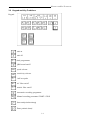
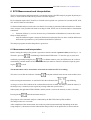
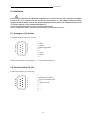
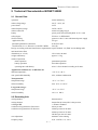
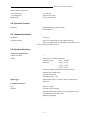
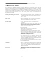
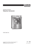
TABLE OF CONTENTS
Table of Contents
1
GENERAL ..................................................................................1-1
1.1
1.2
Application ............................................................................................ 1-1
Unit design ............................................................................................ 1-1
2
3
PATIENT’S AND UNITS SAFETY............................................2-1
OPERATING ELEMENTS..........................................................3-1
3.1
3.2
View ..................................................................................................... 3-1
Keypad and key functions .................................................................... 3-2
4
PUTTING INTO OPERATION ...................................................4-1
4.1
4.2
4.2.1
4.2.2
4.3
4.3.1
4.3.2
4.3.3
Insertion of recording paper .................................................................. 4-1
Application of electrodes ...................................................................... 4-1
Resting ECG ......................................................................................... 4-1
Exercise ECG ....................................................................................... 4-3
Switching the unit on and off ................................................................ 4-4
Mains operation .................................................................................... 4-4
Battery operation .................................................................................. 4-4
Switching ON and OFF ........................................................................ 4-4
5
ECG RECORDING .....................................................................5-1
5.1
5.2
5.3
5.4
Recording in manual mode ................................................................... 5-1
Recording in automatic mode ............................................................... 5-2
Recording with ergometry (remote start) .............................................. 5-3
Recording a test ECG .......................................................................... 5-4
6
ECG MEASUREMENT AND INTERPRETATION ....................6-1
6.1
6.2
Measurement and interpretation ........................................................... 6-1
Analysis results ..................................................................................... 6-2
7
8
UNIT SETUP...............................................................................7-1
INTERFACES .............................................................................8-1
8.1
8.2
Analogous (1V) outlets ......................................................................... 8-1
Serial interface RS 232 ......................................................................... 8-1
9
TECHNICAL CHARACTERISTICS ..........................................9-1
9.1
9.2
9.3
9.4
9.5
9.6
General data ......................................................................................... 9-1
Recording unit ...................................................................................... 9-1
ECG section ......................................................................................... 9-2
Operation section .................................................................................. 9-3
Standard interfaces ............................................................................... 9-3
ECG analysis software ......................................................................... 9-4
10
11
12
CLEANING, DISINFECTION ....................................................10-1
MAINTENANCE, CHECKS .......................................................11-1
ENVIRONMENTAL PROTECTION/WASTE REMOVAL .........12-1
Annex 1 Unit symbols used
Annex 2 Advice on handling thermoreactive recording paper
Unit No.
0-1
MANUFACTURER´S LIABILITY
Manufacturer’s Liability
The manufacturer can only be made liable for possible effects concerning safety, reliability,
and performance of the unit, if
- installation works, extensions, resettings, changes, or repair works are executed by persons authorised by
the manufacturer;
- the electric installation of the room meets the requirements of the applicable regulations;
- the unit is applied in accordance with this operating manual.
This unit may only be operated with accessories and other parts supplied from us. Otherwise, it may come to
defects or false information.
0-2
APPLICATION
1
General
1.1
Application
BIOSET 9000E is a 6/12-channel electrocardiograph.
As a variant, the unit can be supplied with automatic ECG measurement function or automatic measurement/
interpretation using the HES analysis program by the Medizinische Hochschule Hanover.
If desired, it is also possible to unlock the ECG measurement/interpretation function in the client’s house.
BIOSET 9000E is foreseen for ECG recording in the ambulant practice and clinical routine.
Owing to its small dimensions, low weight, and possible battery operation it is suitable for
home visits and emergency medicine.
1.2
Unit Design
BIOSET 9000E is a compact unit with horizontal upper side.
The casing consists of two plastic shells with easy-to-clean surface. The lower part is the chassis which
includes the most significant components.
The main components of BIOSET 9000E are:
Lower casing part with
- circuit board with the entire electronic system
- recording unit as a separate module
Upper casing part with
- keypad including LEDs
The power pack is inside the unit; it is a plug-in type and can easily be exchanged.
The software is installed in a flash ROM memory. Through the RS 232 interface, it can easily be updated.
1-1
PATIENT`S AND UNIT`S SAFETY
2
Patient’s and Unit’s Safety
BIOSET 9000 is in accordance with the Medical Products Act (MPG) and the “Directive 93/42/EEC
on Medical Devices (MDD)” and meets thus the safety requirements as per EN 60 601-1 (IEC 601-1)
and the anti-interference requirements as per EN 60 601-1-2 (EMC act).
According to the above guideline, the unit falls under the risk class IIa.
In order to protect both patient and personal, the unit must be grounded.
The unit complies with the protection class I. This way, it will be grounded through the protective conductor. Any usage of mains-connecting facilities which can cause the protective conductor to be interrupted is
forbidden.
The unit is defibrillation- proof, provided, the patient’s cable supplied with the accessories is used. During
defibrillation, one must not touch the patient, the equipment or the bed.
In case that the unit is used for ECG acquisition from patients with heat pacemakers, or if a further electrical simulator is used simultaneously, the is no kind of endangering. Naturally, simulator should be used in a
reasonable distance from the electrodes. In case of doubt, the patient should be disconnected from the electrocardiograph.
The unit should be operated inside rooms protected against vibrations and corrosive gases, and should not
be exposed to direct sun radiation or heat from other sources. The unit works at ambient temperatures of
10° C ... 40° C.
For the safe operation to obtain, keep the unit free from condensation water. In order to prevent that, make
the unit acclimate after relevant temperature alterations.
Once temperature and atmospheric humidity have compensated, the unit can be operated.
The unit is not intended to be run inside explosion-hazardous locations. If inflammable gas mixtures (e.g.
ether) are present, explosion hazard cannot be excluded.
Connection of a PC to the RS232 interface requires the fulfilment of the standards by both PC and peripheral units. As per the IEC 601-1-1 (compound operation of electrical, medical equipment and electrical, nonmedical equipment), the PC set must be located in a distance of ³ 1.5 m to the patient.
In case that the unit’s instruction manual does not indicate whether a certain compound operation or coupling with other equipment is possible any kind of danger, a relevant information must be obtained from the
manufacturer/supplier, or from an expert, in order to ensure that the total safety of all included units is not
affected.
A situation of danger might arise, if more than one unit are connected to the patient, or at the electrocardiograph, and the sum of all discharge currents would be beyond the permissible limits.
The units are allowed to be used only by persons, who due to their education, knowledge, and practical experience can guarantee proper handling and who have been made familiar with the unit in consideration of
the operating manual.
Only those persons who due to their knowledge and practical experience are fit for briefing people on the
handling of the device are allowed to instruct them.
F
This operating manual is part of the electrocardiograph and must always be on hand. Strict observation of it is precondition for proper use, on which both patient’s and operating personnel’s safety are
depending.
2-1
OPERATING ELEMENTS
3 Operating Elements
3.1 View
Upper Side:
1
2
3
4
Rear side:
5
6
7
8
9
remote start inlet
RS 232C interface
1V-outlet
mains cable socket
potential equalisation connection
3-1
cover opening button
cover of paper chamber
keypad
ECG inlet
KEYPAD AND KEY FUNKTIONS
3.2 Keypad and Key Funktions
Keypad
unit on
unit off
... lead programmes
QRS-sound on/off
speed selector
sensitivity selector
1mV-test pulse
AC filter on/off
muscle filter on/off
Automatic recording programme
Manual recording proramme START / STOP
Start analysisorbereitung)
Enter patient's data(in Vorbereitung)
3-2
INSERTION OF RECORDING PAPER
4 Putting into Operation
4.1 Insertion of Recording Paper
The unit requires thermoreactive recording paper as a block of continuous stationary of 400 sheets, with
a width of 210mm and a total length of 60 m.
To ensure good recording quality and proper paper run, it is recommended to use only original
recording paper; it can be ordered from company von Berg Medizingeräte GmbH, order No. 2700-000-021.
New recording paper should be loaded when a red marking strip appears at the lower paper margin. If all
paper is out, recording is stopped and
the indicating lamp
lights.
Recording paper must be inserted as follows:
- press the cover opening button to release the cover
- bring the cover into upright position and put it aside
- insert the paper block into the chamber, place properly, press it slightly inward and pull some paper out
(before reinserting the cover!)
F
Insert the block in such a manner, that the imprint side gets visible if the paper and is pulled to the
left . The black paper marks must be downside (towards the operator).
- reinsert cover
- bring the recording paper into a symmetric position toward the cover
- close the cover by slightly pressing its left verge
For advice on handling thermoreactive recording paper, refer to annex 2.
4.2
Application of Electrodes
4.2.1 Resting ECG
Connect the delivered patient cable to the inlet marked as ECG INLET (ref. to p. 3-1) and fix it using the
two screws.
F
Defibrillation protection of unit will only be effective, if that patient cable specified in accessories
is used!
The accessories include 4 clamp electrodes for limb leads, and 6 chest wall suction electrodes.
Depending on the patient, prepare the application points, i.e. remove hairs and clean with alcohol. For application at the chest wall, slightly apply electrode gel to the skin areas.
For the limb electrodes, the their clamps should be prepared with electrode gel, as well.
In case of use of an ECG suction electrode system, please refer to the advice given in chapter 4.2.2.
In the following, there is an overview on the standard arrangement of electrodes.
4-1
APPLICATION OF ELECTRODES
Einthoven and Goldberger Limb Leads
Electrode Code Colour
Electrode Position
R
L
F
N
RH arm
LH arm
LH leg
RH leg
red
yellow
green
black
Lead
Linkage of Electrodes
I
II
III
L-R
F-R
F-L
aVR
aVL
aVF
R-LF
L-RF
F-RL
Electrode Code Colour
Electrode Position
C1
C2
C3
C4
4th interspace, RH sternal border
4th interspace,LH sternal border
LF=(L+F)/2
RF=(R+F)/2
RL=(R+L)/2
Wilson Chest Wall Leads
C5
C6
white & red
white & yellow
white & green
white & brown
between C2 and C4
5th interspace, LH
midclavicular line
white & black LH anterior axillary line, on
altitude of C4
white & violet LH central axillary line, on
altitude of C4
Lead
V1,
V2,
V3,
V4,
V5,
V6,
4-2
Linkage of Electrodes
V7
V8
V9, V3R
V4R
V5R
V6R
C1-CT
C2-CT
C3-CT CT=(R+L+F)
3
C4-CT
C5-CT
C6-CT
APPLICATION OF ELECTRODES
Nehb Leads
Electrode Code Colour
Electrode Position
CN1/C1
CN2/C2
white & red
white & yellow
CN3/C3
white & green
2nd rib, RH sternal border
LH posterior axillary line on
altitude of apex beat
above apex beat
Lead
Linkage of Electrodes
D
A
J
C2-C1
C3-C1
C3-C2
4.2.2 Exercise ECG
The exercise ECG is acquired using either a suitable ECG suction-type electrode system or
adhesive electrodes and connected patient cables.
F
Defibrillation protection of unit will only be effective, if that patient cable specified in accessories
is used! For use of an ECG suction-type electrode system, consider possible pieces of advice of
the instructions.
Apply the electrodes to the skin areas specially prepared in advance.
Compared with the resting ECG, a modified positioning of the extremity electrodes will be
required due to muscle exercises.
Ergometry Leads acc. to Rosenkranz and Drews:
(position further electrodes on the thorax acc. to Wilson)
classic application points in the scapula area
change paravertebral
4-3
SWITCHING THE UNIT ON AND OFF
4.3
Switching the Unit on and off
The unit can be energised using either the included, rechargeable power pack or the main supply.
4.3.1 Mains Operation
Connect the mains inlet (chapter 3-1, item 8) and the grounded mains socket of the room using the mains
(green LED) glows.
cable; the charge indicator
Depending on its charge, the power pack is automatically and permanently recharged. The unit can be permanently plugged in without damages occurring to it or its power pack.
Recharging of a completely discharged power pack would take approx. 2 h.
4.3.2 Battery Operation
The mains inlet of the unit is not connected to the mains socket - the charge indicator (green LED) does not
glow.
In case that the battery is to be used not so much, battery operation should be selected only
when an electrocardiogram must be registered very quickly, and a mains socket is not
available. A completely charged battery provides a minimum of 1 h of 6-channel recording
at 25mm/s.
Discharge of the power pack is indicated by both acoustic and optical warning. Once the charge is low
(20 %), the indication
will change into permanent light, and a warning sound comes in certain
intervals. After these signals have come, there is only a few time left for recording.
Once the power pack is discharged, a short, permanent sound comes, and the indicator blinks. After that,
the unit goes automatically off.
In order to get a maximum operation time per power pack charge, the unit has a sleep mode. That means
that after an acoustic warning the unit will always get off automatically after no key was pressed for
4 minutes. If the recording process lasts longer, the unit, of course, remains on.
4.3.3 Switching ON and OFF
Use the key
to switch the unit on.
After completion of a switch-on routine, the selected programme (usually PR1) is activated, provided that
the electrodes have been properly arranged. (For information on electrode faults, refer to chapter 5.1).
Use the key
to switch the unit off.
4-4
ECG RECORDING
5 ECG Recording
ECGs can be recorded under MANUAL with PR1 … PR5 and AUTOMATIC.
After switching-on - with electrodes applied - the programme selected in the setup (usually PR1) is indicated
by permanent light of the relevant green LED.
5.1
Recording in Manual Mode
The following parameters can be changed prior to or during recording. The active selection is indicated by
the relevant LED.
Use the keys
...
to select the lead programmes.
The following standard 12 or 6-channel programmes can be selected:
PR 1:
I, II, III, aVR, aVL, aVF, V1...6 (12 standard leads)
PR 2:
I, II, III, aVR, aVL, aVF (limb leads)
PR 3:
V1...V6 (chest wall leads)
PR 4:
aVL, I, -aVR, II, aVF, III (Cabrera)
PR 5:
I, II, III, D, A, J (limb and NEHB leads)
.
Change the recording speeds of 5, 25, 50 mm/s using the key
Change the sensitivities of 5, 10, 20 mm/mV using the key
Use the key
to switch the muscle filter ON and OFF.
Use the key
to switch the AC filter ON and OFF.
.
The drift filter for reduction of the zero line variation is usually ON, however, it can be switched OFF in
the unit setup.
Muscle, AC and drift filters act simultaneously for all channels.
F
Since the task of filters is it to ‚filter out‘ certain frequency ranges, this will result in a change
of the ECG curve. Therefore, one should always try to eliminate the source of fault before
switching muscle or AC filter ON.
Use the key
to switch the QRS sound, i.e. the acoustic signal per QRS complex , ON and OFF.
Recording can be started, once the indicator
blinks in rhythm with the heart rate, or – if the QRS
sound is on – the heart rhythm can be heard.
After electrode application, there are polarisation voltages. They have first to stabilise before a properly centred recording can be
made.
Start recording by pressing
.
During registration, the 1 mV test pulse can be indicated at any time
Stop recording by pressing once more
.
.
If sheet or time control according to chapter 7 is selected, recording stops automatically.
5-1
RECORDING IN MANUAL MODE
Electrode Faults:
Every ECG acquisition includes a permanent test of all electrodes.
In case that electrode fault occur, those LEDs start blinking, the programmes of which include faulty electrodes. That means in particular:
If the electrodes R, L, F or N are faulty, LEDs PR1...PR5 start blinking.
If the electrodes C1, C2 and C3 are faulty, the LEDs of the programmes with chest wall leads and/or
NEHB leads, i.e. PR1, PR3 and PR5 start blinking.
If the electrodes C4, C5 and C6 are faulty, the LEDs of the programmes with chest wall leads, i.e. PR1 and
PR3 start blinking.
The selected programme lights again after the sources of electrode faults were eliminated.
In case that electrodes drop off in the course of further ECG acquisition, the above mentioned fault indication will take place.
F
In case that the ECG is recorded despite of indication of electrode faults, only those leads,
the electrodes of which are in proper condition, are recorded.
Intermediate settlement:
Dropped-off electrodes, distinct artefacts or insufficient waiting time after electrode application
may be the reason of zero line fluctuations during ECG acquisition.
An ,intermediate settlement’ can be initiated by pressing the same key once more.
The ECG curve - caused by the time constant switched over - shows a changed signal form being marked
additional by a 1 mm marking at the lower paper margin.
Defibrillation during ECG recording will lead to overload of the ECG inlet. To eliminate this overload,
there is an automatic settlement without time limitation after defibrillation. The ECG curve being now
visible again shows, owing to the switched-over time constant, a different signal form which is marked
additionally by marks at the lower and upper margin of the paper strip.
After completion of the intermediate settlement, the ECG is again recorded with normal time constant.
Once defibrillation was made, this can be done approx. 30s after the defibrillation, depending on the
defibrillation energy.
F
This mode can activate itself automatically in case of loose electrodes or other significant artefacts.
F
In case of heavy artefacts or electrode drop, the heart rate found may not be correct in every case.
For pacemaker patients, it cannot be fully excluded that the SM pulses for heart rate
measurement
are taken for ventricular complexes, or ventricular complexes are suppressed. In
any case, additional
ECG testing is required.
5.2 Recording in Automatic Mode
In AUTOMATIC MODE, 12 standard leads (limb leads PR2 and chest wall leads) are registered with the
registration length (1 to 4 sheets per programme) selected in the Setup.
Recording can be started, once the indicator
blinks in rhythm with the heart rate, or – if the QRS
sound is on – the heart rhythm can be heard.
Use key
to start automatic registration.
The AUTOMATIC programme runs with filter setting, speed and sensitivity, as selected before starting it.
After completion of the automatic registration, the system returns to that programme which has been selected before starting it.
5-2
RECORDING WITH ERGOMETRY
Recording of both programmes runs time-synchronously.
Time-synchronous means that 12 leads are acquired simultaneously, and a maximum of 10 seconds of an
electrocardiogram are saved. Hence, programme 2 is registered directly, and programme 3 - time-synchronous to PR 2 from the memory.
All settings with regard to speed, sensitivity, Muscle and AC filter, as well as QRS sound are made according to chapter 5.1.
Using the
key, the programme can be cancelled at any time.
5.3 Recording with Ergometry (Remote Start)
The remote start facilitates automatic ECG recording on change of load stage.
The start of recording is induced by the ergometer. Recording is made for the currently selected lead
program. Recording stops automatically when the selected recording time is up.
The duration of recording can be sheet- or time-controlled and is made in the Setup (chapter 7).
Also in the setup, the interface is set for the ergometer to be used.
If one of the ergometers mentioned below is used, the control of ECG recording and data exchange by
means of the appropriate cable is accomplished through the RS 232 interface (p. 3-1, connector 6).
(Data exchange is the recording of the concerned load (for Ergometrics 900 additionally the last measured blood pressure).
The following ergometers can be connected:
Unit
Cable
Item No.
Ergometer SECA 100 (from YOM 99)
Ergometer Ergometrics 900
Ergometer Variobike 550
starter cable SM
connecting cable EL
connecting cable BO
2700-050-000
2100-068-000
2100-062-000
Connection of a Monitor
Additionally it is possible to connect a monitor, using a monitor cable, to the 1 V outlet
(p. 3-1, connector 7).
unit
designation
item No.
EMC 1000 monitor, elmed
monitor cable EM
2500-072-000
The 1 V outlets are allocated to the following recording channels (standard):
PR 1 channel
PR 2 channel
PR 3 channel
PR 4 channel
PR 5 channel
outlet 1
outlet 2
outlet 3
8
1
2
2
1
10
2
4
4
2
12
3
6
6
3
5-3
RECORDING A TEST ECG
5.4 Recording a Test ECG
For demonstration purposes, the unit includes an ECG simulator.
and
The simulator can be opened at any time by simultaneous pressing
.
Now it is possible to record manually or automatically and to easily demonstrate setup variants, particularly
the effect of filters.
For safety purposes, the recording strip includes the marking ‘Test ECG’.
The simulator can be closed by simultaneous pressing
and
.
If a test ECG is desired to demonstrate measurement/interpretation, proceed as described in chapter 6.1.
Input of patient’s data: 30 years old, male.
5-4
ECG MEASUREMENT AND
INTERPRETATION
6 ECG Measurement and interpretation
The ECG measurement and interpretation is executed by means of ht HES analysis program. By the buyer’s
desire, it can be unlocked either in his premises or before despatch.
ECG evaluation requires the I, II and V1 to V6 leads were acquired over a period of 10 seconds (the III, aVR,
aVL and aVF leads are calculated).
To obtain reliable analysis results, take care that ECG recording is performed without interference. Furthermore, analysis is not possible with leads according to Nehb, and in case of electrode faults or intermediate
settlements.
F Inclusion of filters is, as a rule, the worst way of elimination of disturbances, because this is most
likely to falsify the ECG.
Only the unfiltered signal is analysed. With muscle and mains filter on, there would be differences
between the representative cycles (unfiltered) and the ECG (filtered).
The analysis program considers the patient’s age and sex.
6.1 Measurement and interpretation
Before starting the analysis, the patient’s age and sex must be entered as patient’s data (use the keys 1 ...0).
Therefore, press key
. On blinking of the left-hand LED below ‘Y’ enter the age (in years) and
confirm by repeated pressing this key
. For children under 4 years, the LED below ‘M’ will now
start blinking, and the months of life of the unfinished year must be entered. Confirm this input by pressing key
as well.
The measurement can be started after 10 seconds of trouble-free ECG recording.
This is the case if after the indicator’s blinking
in rhythm with the heart rate one waits another 10 sec
before starting the mesurement, or until the LED in the indication field
stops blinking.
As long as a 10-sec-ECG which can be evaluated has not been recorded, the analysis cannot be started, i.e.
the analysis key is locked (acoustic signal on pressing within the rejection time.)
Subsequently the right-hand LED will blink, and the patient’s sex must be entered (1=male, 2=female).
Pressing the key
starts the automatic analysis.
The progress of the automatic analysis is indicated by the PR1 LED, later by PR2 and PR3.
The analysis takes 4 to 5 seconds.
After completion of the measurement, the results are printed out automatically. Depending on the unit
setup (chapter 7), the measured-value table and the analysed ECG can be printed out in various formats.
6-1
ECG MEASUREMENT AND
INTERPRETATION
6.2 Analysis results
The following information is given out after the patient’s data:
- Heart frequency in beats per min.
In case of adults, for a heart rates of more than 100 beats per min., a hint on TACHYCARDIA will be
inserted, and for rates of less than 60 beats per min., a hint on BRADYCARDIA.
For children:
a hart rate <60 beats per min. gives a hint on BRADYCARDIA;
a hart rate 60 to 70 beats per min. gives a hint on AGE-CONDITIONED BRADYCARDIA;
a hart rate >120 beats per min. gives a hint on TACHYCARDIA;
- Global measured values
P-duration, P-Q interval, QRS duration, Q-T interval, QTc as the Q-T interval corrected acc. to
BAZETT, as well as this relative Q-T interval in percent (normalised to a Q-T duration of 0.39 s at a
heart frequency of 60 beats per minute acc. to HOLZMANN).
Intervals marked by a star (*) differ from the normal values.
- Frontal vectors
in the frontal plain, longest vectors for P wave, QRS complex and T wave in the Cabrera circle;
indication of the position type for the QRS vector
- Rhythm
Indication of rhythm with hints , e.g., for sinus rhythm, sinus arrhythmia, ventricular extrasystoles,
arterial fibrillation.
The rhythm analysis considers R-R distances, P- and T-wave forms, morphology of QRS complex, and
coupling relations.
- Rhythm diagram
* brief survey on the beat sequence of ECG cycles with a statement on how many beats have been in
cluded by the 10 s recording into the evaluation
* meaning of the characters/letters
”+”
”normal beats” included in the mean-taking process for the representative cycle
Not included in the message:
”2,3,4” the respective beat is an extrasystole or an aberrant complex
(each figure stands for a different type)
”B”
base-line fluctuation
”P, T” aberrations of P- or T-contours
”O”
aberrations of P- and T-contours
”R”
too short intervals towards the preceding and following cycle
“X”
other variations
“V”
position at the beginning or end of the 10-sec-ECG
“U”
aberrant complex, complex with spikes
“!”
pacemaker-triggered beat
* The distance between characters represents, in the roughened grid, the R-R distance
- Findings
* found disturbance in the raw data ECG including qualification: slight, medium or heavy
* Indication of QRS waves occurred
in limb (EX) leads: I, II, III, aVR, aVL, aVF
and chest wall (BW) leads: V1 - V6
* interpretation of significant ECG measured values for morphologic individualities, e.g. Q wave in
certain leads, R losses, Delta waves, ST changes
* repolarisation disturbances by inner and outer layer type as well as graduation
6-2
ECG MEASUREMENT AND
INTERPRETATION
- QT Dispersion
In the HES ECG, the QT dispersion is indicated as the dispersion of earlier repolarisation, measured from
the QRS beginning up to the extrema of the T wave (QT-peak dispersion).
The QT dispersion shows the standard deviation of the moments of T extrema together with the absolute
value of the maximum time difference of these values as well as the number of the leads used for calculation,
applied to the 8 measuring leads.
- QRS-T Evalation
Interpretation of the representative cycle after diagnosis of infarction, hypetrophy/bundle branch block
etc.
ECGs of children (under 14) are not subjected to QRS-T evaluation in order to avoid misunderstandings.
- Finally the ECG is subjected to an overall evaluation.
In addition to the analysis results, lead II of the analysed ECG is shown in unfiltered condition at 10 mm/sec.
Representative Cycles (optionally selectable)
- shows the mean value of the ”normal beats” with markings for P beginning, P end, QRS beginning,
QRS end, and T-end (50 mm/s - unfiltered)
- additional recording of the measured ECG lead II at 10mm/sec (unfiltered)
Measurement Results (optionally selectable)
Out of the 12 standard leads, it will be put out:
- measured values of QRS range
Q-, R-, S-duration; Q-, R-, S-amplitude; ratio of Q/R and R/S amplitudes as well as the integral of
the QRS range
- measured values of ST-T range
ST amplitudes; positive and negative T-amplitudes, as well as the integral of the T-wave
- measured values of P-range
positive and negative amplitudes of P-wave, as well as the integral of the range.
FAny computer-aided evaluation or interpretation must be checked (and be given remarks, if need
be)
and signed by a physician.
More detailed explanations about the analysis results and the algorithm of the ECG analysis are given in the
HES MWZ ECG manual for the Hanover ECG program.
6-3
UNIT SETUP
7 Unit Setup
The unit Setup allows customisation according to the user’s desire.
Unit setup means that the unit start with changed parameters.
All parameters to be selected by function keys (marked with *) can of course be changed during operation.
Can following parameters can be customised:
- the lead programme made default *
- recording speed of all programmes *
- sensitivity of all programmes *
- number of sheets for AUTOMATIC programme (every individual lead sequence)
- in MANUAL mode, start/stop operation, or selectable number of sheets or recording time
- muscle filter ON / OFF *
- AC filter ON / OFF *
- QRS sound ON / OFF *
- drift filter ON / OFF *
- language for paper margin imprint (and measurement results)
- RS232 mode: OFF, remote control, data transfer from ergometer, PC linkage (PC Link is an online data
transfer format ”0002” of HOERMANN)
- ECG recording at change of load stage (remote start ergometry)
- date and time
- setup of optional measurement and interpretation
Operation
+
The Setup is opened by simultaneous pressing of
.
(Apply these setting only in ready-to-work condition, i.e. with loaded paper)
F
As soon as
is blinking, the unit is in SETUP mode.
The individual parameters are set up as follows:
parameter
programme
key
blinking
LEDs
variant
programme
PR1
selection
change
accepted
PR2
PR3
permanent light of sel. programme
PR4
PR5
speed
speed
5mm/s
25mm/s
permanent light of selected speed
50mm/s
sensitivity
sensitivity
5mm/mV
10mm/mV
20mm/mV
7-1
permanent light of sel. sensitivity
UNIT SETUP
parameter
no. of sheets (AUT.)
key
blinking
LEDs
variant
speed 25
1sheet *)
2sheets *)
selection
change
accepted
-
3sheets *)
4sheets *)
*) Since the ECG memory accepts a maximum of 10 seconds, it is recommended to select only 1 or 2 sheets for a
recording speed of 25 mm/s, or 1 sheet for 5 mm/s.
MAN. recording
speed 5
- **)
1sheet **)
2sheets **)
-
5s **)
10s **)
**) selectable recording speed:
without sheet control, i.e. recording must be stopped manually
1, 2 sheets
sheet control, i.e. recording stops automatically after selected number of sheets
5, 10 s
time control, i.e. recording stops automatically after selected recording time
muscle filter
muscle filter
on
permanent light if ON
off
AC filter
AC filter
on
permanent light if ON
off
QRS sound
QRS sound
on
permanent light if ON
off
drift filter
speed 50
on
-
off
language
sensitivity 5
1 (German)
2 (English)
-
3 (Russian)
-
4 (French)*
5 (Czech)
Instead of 3 (Russian), the unit having the unit No. includes according to page 0-1
Slovak ( ), Romanian ( ),
( )
Instead of 4 (French), the unit having the unit No. includes according to page 0-1
, Slovak ( ), Romanian ( ),
( )
Instead of 5 (Czech), the unit having the unit No. includes according to page 0-1
Slovak ( ), Romanian ( ),
( )
* with interpretation texts in English
7-2
UNIT SETUP
parameter
key
RS 232 mode
blinking
LEDs
variant
sensitiv. 20
off
selection
change
accepted
remote contr.
SECA100
-
Ergometrics
PC-Link
Erg-y recording
+
speed 5/25
0
1sheet
2sheets
-
5s
10s
+
date and time
PR1 + PR2
Date and time (day, month, year, hour, minute, second) have to be entered in the following way:
ddmmyyhhmmss
Use the following keys to enter the digits:
for 1,
for 2,
for 3,
for 4,
for 5,
for 6,
for 7,
for 8,
for 9,
for 0.
Every input is confirmed by a beep. In any case, it must be 12 digits.
Changes and corrections require complete reinput of the digits.
Optional print-outs of measurement and interpretation:
Settings for print-outs in addition to the measurement/interpretation results:
rep. cycles
sbsqntly.
**+PR1
yes
permanent light of active condition
no
meas. val. table
sbsqntly.
**+PR2 yes
permanent light of active condition
no
Programming of the also printed ECG acc. to measurement/interpretation results:
print ECG
sbsqntly.
**+PR3
yes
permanent light if ON
no
number of chann.*)
sbsqntly.
**+PR4
PR1=12ch.
permanent light if ON
PR2+3=6ch.
*) ECG recording using the PR1 (12 channels), or successively using PR2 and PR3.
**) blinking LEDs: speed, sensitivity
7-3
UNIT SETUP
parameter
number of sheets
key
sbsqntly.
blinking
LEDs
variant
selection
**+PR5
1 sh. each*)
change
accepted
2 sh. each*)
3 sh. each*)
permanent light if ON
4 sh. each*)
*) Since the ECG memory can store max. 10 seconds, it is advisable to select only 1 or 2 sheets for recording at 25
mm/sec, and only 1 sheet for 5 mm/sec.
sbsqntly.
speed
**+PR1+PR5
curr. speed.*)
5 mm/sec*)
25 mm/sec*)
permanent light if ON
50 mm/sec*)
sensitivity
sbsqntly.
**+PR2+PR5
curr.sty. *)
5 mm/mV*)
10 mm/mV*)
permanent light if ON
20 mm/mV*)
**) blinking LEDs: speed, sensitivity
As long as the system is in SETUP mode, any changes can be made.
+
Setup is closed by simultaneous pressing of
.
Closing saves all parameters settings.
After that, all settings are automatically printed out.
The indication
F
stops blinking.
The printout of the unit setup gives a detailed overview of all settings and, if existing, special
variants. Preferably, it should be kept with the operating manual.
7-4
INTERFACES
8 Interfaces
It must be provable that any additional equipment to be connected to the unit’s analogue and digital
interfaces are in accordance with the relevant EN specifications (i.e. EN 60950 for data-processing
equipment and EN 60601-1 for electro-medical equipment). Furthermore, all combinations must be in
accordance with the system standard EN 60601-1-1.
All non-medical units must be connected to the same circuit.
In case of questions, please contact your local dealer or the technical service.
8.1 Analogous (1V) Outlets
Connection scheme (seen onto socket)
1
2
3
4
5
6
7
8
9
—
GND
outlet 2
QRS trigger outlet
—
—
outlet 1
outlet 3
—
Allocation of outlets of programmes 1 ... 5 is desribed in chapter 5.3
8.2 Serial Interface RS 232
Connection scheme (seen onto plug)
1
2
3
4
5
6
7
8
9
—
RxD (Received Data)
TxD (Transmitted Data)
—
GND (Ground)
—
—
—
—
8-1
TECHNICAL CHARACTERISTICS
9 Technical Characteristics BIOSET 9000E
9.1 General Data
operation
mains voltage range
mains and battery
230 V ± 10%, AC
power drain
mains frequency range
22 W
50 Hz / 60 Hz
mains connection
battery
mains lead, plug-in type
power pack, nickel-metal hybride 12 V; 2.1 Ah
safety degree
electrical safety
IP 20 acc. to DIN 40050
protective class I / unit with internal power supply
application class
potential equalisation connection
CF type
at the ECG unit
classification acc. to “Directive 93/42/EEC”MDD
class IIa
Design according to the anti-interference requirements as per EN 60601-1-2 (EMC act) including radio
anti-interference filter.
dimensions (w x d x h)
358 x 340 x 98 mm3
weight with battery
modes of operation
approx. 5.5 kg
mains operation
battery operation
operating time with battery
permanent operation
short-time operation
min. 1 h for 6-channel recording at 25 mm/s
Application conditions acc. to DIN IEC 721
ambient temperature
+10 °C to +40 °C
max. permissible humidity
95%, without condensation
Transportation:
temperature range
relative humidity
-25 °C to +70 °C
max. 95 % at +40 °C
Long-term storage:
temperature range
-25 °C to +55 °C
relative humidity
10 % to 100 %
9.2 Recording Unit
writing method
writing element
thermoreactive
thermoline 210 mm wide, 8 dots per mm,
writing width
> 40 mm / channel
resolution of registration in Y direction
resolution of registration in X direction
8 dots per mm
20 dots per mm at 50 mm/s
40 dots per mm at 25 mm/s
200 dots per mm at 5 mm/s
zero adjustment
frequency range
automatic write centring
0,05...120 Hz +5 % -30 %
9-1
TECHNICAL CHARACTERISTICS
recording paper
continuous stationary, 400 sheets, 210 mm wide, 60 m long,
with grid imprint, red side logo, sheet control marks
paper type
recording speeds
thermoreactive, order No. 2700-000-021
5, 25, 50 mm/s ± 5%
9.3 ECG Section
electrode inlets:
Einthoven
Wilson
R, L, F, N,
C1, C2, C3, C4, C5, C6,
Nehb
electrode test
C1=CN1, C2=CN2, C3=CN3,
monitoring before and during ECG acquisition
number of channels
lead programmes
12, 6
PR 1
PR2
I, II, III, aVR, aVL, aVF, V1 ... V6 (12 standard leads)
I, II, III, aVR, aVL, aVF (limb leads)
PR 3
PR 4:
V1 ... V6 (chest wall leads)
aVL, I, -aVR, II, aVF, III (Cabrera)
PR 5:
progr. sequence for AUTOMATIC Mode
I, II, III, D, A, J (limb and NEHB leads)
PR2 and PR 3; time-synchronous
recording duration per lead programme
application unit
optional 1 - 4 sheets, to be selected in the unit Setup
F insulated
input resistance
time constant
>2 x 50 MOhms
3,2s
overload protection
for voltage pulses from defibrillators and cautery
apparatuses; automatic intermediate settlement
rejection factor (IMMR)
equivalent interference voltage (p-p)
> 100 dB
< 20 µV
superposed DC voltage
transmission range
< ± 0,3 V
0,05 ...150 Hz
sensitivities
muscle filter
5, 10, 20 mm/mV ± 5 %
fg = 35 Hz (slope: 4 ...6 dB/Okt.)
mains frequency filter
drift filter (ADS)
adaptive digital filter; 50/60 Hz ± 2 %, (damping: > 20 dB)
high-pass; limit frequency (3dB): 0.6 Hz ± 0.1 Hz
signal delay <1.1s; enabled (default); can be disabled in the
unit Setup
AD conversion
pacemaker
scanning frequency 1000 Hz, resolution: 13 bit
recognition, marking
(pacemaker voltage on body surface < 700 mV, pacemaker
pulse width <2 ms; also double-chamber pacemakers)
9-2
TECHNICAL CHARACTERISTICS
heart frequency indication
measuring range
30 - 240/min
recording paper
QRS sound
print-out of average
can be switched off
9.4 Operation Section
keyboard
plastic-foil keypad; wipe-resistant
LED indicators
9.5 Standard Interfaces
signal inlet
TTL level
registration mode
mode 1: L registration start, H registration stop
mode 2: L registration start, automatic registration acc. to
time or number of sheet selected
9.6 Optional Interfaces
Analogous signal outlets:
number of outlets
outlets
3
short-circuit resistant, asymmetric,
frequency range:
0.05 … 250 Hz
sensitivity:
1.00 V / 1 mV
0.50 V / 1 mV
0.25 V / 1 mV
sensitivity change synchronous to inlet sensitivity
channels time synchronous;
DA converter: 8 bits,
QRS trigger:
modulation range: ± 4V
digital outlet signal 5 V, 150 ms; time-synchronous to
ECG inlet
Computer interfaces:
type
function
RS 232 C, 9-pole
PC-Link for PC coupling
data communication with SECA 100, Ergometrics 900,
(Variobike550, Variotrainer500)
update programming
9-3
TECHNICAL CHARACTERISTICS
9.6 Measurement Software
HES MWZ EKG Evaluation program for analysis of resting ECGs
- time-synchronous acquisition of the 12 standard leads
- ECG measurement
- analysis of rhythm and form
- rhythm analysis based on leads II, V1, V6,
- output of complete, analog curves or representative cycles with measurement marks
- output of the measure-value report
- output of the ECG interpretation
9-4
Cleaning, Disinfection
10 Cleaning, Disinfection
Only clean and disinfect the instrument in switched-off condition and disconnected from the mains.
F
Make sure that cleaning and disinfectant agents are only used in compliance with the
manufacturers’ provisions, e.g. in due dilution.
Electrodes, patient cable,
and accessories
- to be cleaned after use acc. to in-house specifications.
General rules
- clean electrodes with running hot water after use.
- disinfect electrodes and cables by means of a disinfectant-soaked
cloth (e.g. Cidex, Gigasept).
Note:
- do not dip plug connectors of cables into fluids.
- the use of acetone, alcohol, chloroform, or strong solvents results
in flexibility loss of and damage to cable.
- gas sterilisation is possible, sterilisation by hot air and steam is
inadmissible.
Unit
- regularly clean it by means of a soft and non-fuzzy cloth, using a
mild soap solution.
- for a necessary disinfection, use Gigasept or the like.
Sterilisation by steam, hot water or air is inadmissible.
Note:
- do not use ether, petrol, propyl alcohol, or acetone.
- prevent fluids from getting into instrument or connecting sockets.
10-1
MAINTENANCE, CHECKS
11 Maintenance, Checks
In the interest of the instrument’s permanent availability and in order to guarantee the required safety for
both patient and operating personnel in handling the BIOSET9000, inspections and checks are specified.
If deficiencies concerning safety and serviceability are thereby detected, inform your service partner. In case
of defects or function deficiencies of the unit, which may impair the safety of both patient and operator, the
unit may be used only after elimination of these faults. Service partners can get a service manual from von
Berg Medizingeräte GmbH.
Checking when Putting into Operation
- new instruments are installed, checked, and handed over in
a functional and safe condition by the manufacturer or his
service partner.
Daily Checks
- prior to using the unit, make a visual check of unit, cables
and electrodes for damages and other defects.
Periodic Checks
- a close functional test should be accomplished every
12 months;
- perform a safety check as per IEC 601-1 and IEC 601-2-25;
- for a function test, advantageously use an ECG simulator;
(if using the internal simulator, patient cables and ECG input section
must be connected before starting the check)
Check the following:
- patient cable and electrodes (visual inspection);
- all printed curves and parameters;
- simulate the external “start” function and monitor signals;
- full functionality of the patient cable. Therefore, remove each
electrode one after the other from the simulator. An electrode
fault must be indicated in every case.
- Evaluate the recording test (see below);
- it is also possible to check recording quality. Therefore, open
and close the unit Setup as described in chapter 7. This will
record the settings plus three parallel, oblique test lines which
allow assessment of the printing quality.
In case that national regulations require more extensive checks,
these must be performed.
Thermoline
- in case of contamination of the thermoline, the printing edge
may be cleaned with utmost care, using an alcohol-soaked
cotton swap. Make sure that the unit is unplugged, and no
patient is connected.
Power Pack
- the power pack is service-free. If with battery operation a
reasonable recording time is not longer achieved, contact a
service partner.
11-1
ENVIRONMENTAL PROTECT. / WASTE REMOVAL
12
Environmental Protection / Waste Removal
Neither the use of the units nor of its accessories causes harmful emissions of waste substances.
The following information applies to all equipment manufactured by us so that parts of it may not apply to
this unit.
Used Units
Classification: electronic waste / waste for recycling
If the customer desires, von Berg Medizingeräte GmbH takes used units back for removal. Reasonably,
individual assemblies are regenerated to be used as spare parts. All other components – separated by types
of materials – are transferred to authorised enterprises for removal.
In case that the customer wants to remove the unit by himself, he may obtain a list of authorised, German
waste removers.
Computers and Components of It
Classification: electronic waste / waste for recycling of waste for recycling being subject to control
Computer and components of it (boards etc.) do, for power supply, often include batteries of power packs
which are either replaceable or fixed. Since, in the course of technical development, it happens that suppliers
of computer components change from power packs to batteries and vice-versa, from soldered to replaceable
types, or change the types to be used, the appropriate way of removal may only be selected after having
seen the components. Also refer to the USED UNITS section.
NiMH Power Packs
Classification: batteries / waste for recycling
Exhausted NiMH power packs must not be removed as normal waste. They include nickel-II-hydroxide
(classified as hazardous waste) and have to be recycled considering the local regulations, or to be removed
in an environmentally friendly way by
- von Berg Medizingeräte GmbH
- local collecting centres
- authorised removers.
NiCd Power Packs
Classification: batteries / waste for recycling being subject to control
Exhausted NiCd power packs must not be removed as normal waste. They include highly poisonous cadmium and have to be recycled considering the local regulations, or to be removed in an environmentally
friendly way by
- manufacturer
- von Berg Medizingeräte GmbH
- local collecting centres
- authorised removers.
Lithium Batteries
Classification: dry batteries / hazardous waste
Exhausted lithium batteries must not be removed as normal waste. They have to be removed in an environmentally friendly way by
- von Berg Medizingeräte GmbH
- local collecting centres
- authorised removers.
12-1
ENVIRONMENTAL PROTECT. / WASTE REMOVAL
Timer Modules
Classification: electronic waste / waste for recycling
If the customer desires, von Berg Medizingeräte GmbH takes electronic waste back for removal. In case
that the customer wants to remove the unit by himself, he may obtain a list of authorised, German waste
removers.
Accessories, Cables, Electrodes, Patient’s Cables
Classification: electronic waste / waste for recycling
As far as possible, these components are repaired by our service. Removal can be accomplished in the same
way as of used units.
Electrode Cream
Classification: normal waste
Depending on local regulations, it can be removed through normal waste bins or as industrial waste.
12-2
Annex 2
Advice on Handling Thermoreactive Recording Paper
In order to achieve best recording quality, and to fulfil the requirements for long-term storage of ECG records,
make sure that following is guaranteed:
- storage of both fresh paper and records at an ambient temperature of <30 OC and humidity < 65 %;
- do not expose it to direct sunlight or neon light for longer time; preferably, store the paper in a dark room;
- avoid longer contact of it with plastics, like PVC (e.g. PVC envelops) or self-adhesive foils (for filling, we
recommend paper envelops);
- do not use glues which contain alcohol or ether;
- do not rub or scratch the paper (friction heat will cause colour changes)
In order to achieve best recording quality and exact paper run, we strongly recommend to use only
company´s von Berg Medizingeräte GmbH original recording paper.
Company von Berg Medizingeräte GmbH shall not be held responsible for malfunctions and defects which
may arise from the use of recording paper other than from us. Malfunctions and defects of this type might be:
- essential deterioration of the writing quality,
- improper paper run
- contamination, or even destruction of the thermoline.
von Berg
Medizingeräte GmbH
Bahnhofstraße 62
D-08297 Zwönitz
(:
(03 77 54) 3 13 33
Fax:
(03 77 54) 3 13 01
e-mail: [email protected]
internet: www.von-berg-medizingeraete.de
von Berg Medizingeräte GmbH intends to continue developing this unit in order to provide the user with the latest state of
technology. That is why technical information and illustrations contained herein are subject to change for the purpose of
technical development.