1
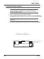
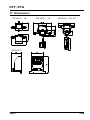
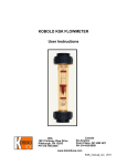
KFF/KFG Low-Volume Flow Meter
User Instructions
KFG_KFF_manual_0304
KFF, KFG
1. General Information
Please read this service manual carefully before unpacking and readying the unit for
operation, and follow the instructions precisely as described herein. These devices may
only be installed, used and maintained by skilled personnel who are familiar with this
service manual and can observe applicable regulations regarding industrial safety and
accident prevention.
2. Contents
1. General Information . . . . . . . . . . . . . . . . . . . . . . . . . . . . . . . . . . . . . . . Page
2. Contents . . . . . . . . . . . . . . . . . . . . . . . . . . . . . . . . . . . . . . . . . . . . . . . Page
3. Suggested Application . . . . . . . . . . . . . . . . . . . . . . . . . . . . . . . . . . Page
4. Operating Principle . . . . . . . . . . . . . . . . . . . . . . . . . . . . . . . . . . . . . Page
5. Unit Check-up . . . . . . . . . . . . . . . . . . . . . . . . . . . . . . . . . . . . . . . . . . Page
6. Mechanical Connection . . . . . . . . . . . . . . . . . . . . . . . . . . . . . . . . . Page
7. Electrical Connection . . . . . . . . . . . . . . . . . . . . . . . . . . . . . . . . . . . Page
8. Electrical Commissioning . . . . . . . . . . . . . . . . . . . . . . . . . . . . . . . Page
9. Mechanical Commissioning . . . . . . . . . . . . . . . . . . . . . . . . . . . . . Page
10. Technical Data . . . . . . . . . . . . . . . . . . . . . . . . . . . . . . . . . . . . . . . . . . Page
11. Dimensions . . . . . . . . . . . . . . . . . . . . . . . . . . . . . . . . . . . . . . . . . . . . . Page
2
2
3
3
4
4
5
6
6
7
8
Manufactured and Marketed by:
Kobold Instruments Inc.
1801 Parkway View Drive
Pittsburgh, PA 15205
Tel: 412-788-2830
Fax: 412-788-4890
Page 2
03/04
KFF, KFG
3. Suggested Application
The KFF and KFG series flow meters are used for measuring small liquid or gas flows.
These units are configured as follows:
Analog output
In order to transmit the measured flow results, an analog output (0-5 V) is provided.
A 500 Hz. max. pulse output is available on some models.
Flow sensor with analog output
Integrated sensor with LCD digital display (3-digit)
The KFF meters may only be used for measurement of low-viscosity, clear
fluids (<10 cSt). Measurement of liquids with higher viscosity can result in significant
measurement errors.
The KFG meters are calibrated at standard conditions in air (14.7 PSIG, 68° F).
Notes for KFG-1 series:
Non-conventional media, pressures or temperatures may require a user calibration on
site, by means of a comparison unit or volumetric test.
Attention! The media to be measured must not be contaminated. In
particular, large particles can cause jamming or destruction of the
rotor.
4. Operating Principle
KOBOLD flow meter KFG and KFF are being used to measure small and very
small flow volumes. The medium to be measured can be in gaseous form (KFG) or
in liquid form (KFF). These units function according to Pelton principle, meaning that
the flowing medium will set a paddle wheel in rotation. The rotary movement is
translated into pulses via photo cells. An electronic integrator uses these pulses to
generate a flow proportional, analog output signal (0-5 V).
03/04
Page 3
KFF, KFG
5. Unit Check-up
These devices are checked before shipment and sent away in perfect condition. Should
the damage to a device be visible, we recommend a thorough inspection of the delivery
packing. In case of damage, please inform your parcel service/ forwarding agent
immediately, since they are responsible for damages occuring during transit.
Scope of delivery
Standard scope of delivery applies:
Flow meter
Connection cable with plug: KF-7000
Instruction manual
6. Mechanical Connection
Before Installation
Please ensure that the actual flow volume is in agreement with the measuring
range of the device. The reference number of measuring range can be read
from the item number label.
Note: Continuously exceeding the measuring range can cause damage
to bearings.
Make sure that the maximum operational pressure and temperature are not
exceeded.
Ensure that there is no remaining packing material inside the unit.
KFG:
The calibration of the unit is performed in horizontal position; the item label faces
upwards. With other mounting positions, a measured-value deviation of 0.25 %/°C at
50% nominal flow should be taken into consideration.
KFF/KFG:
Mount the measuring device on desired position. Two mounting flanges are
supplied for this purpose. Connect unit to your piping system.
Do not remove the meter fittings as the calibration may change.
Attention:When tightening fittings, it is necessary to work with two suitable
wrenches. A transfer of torque on device's housing while tightening
the fittings can result in the destruction of the measuring device.
Check the sealing of all connections.
Page 4
03/04
KFF, KFG
7. Electrical Connections
Attention: Ensure that the voltage level of your supply system
corresponds with the voltage level required by the measuring
device. (+12.5 VDC ± 2 VDC)
Make sure that the electrical supply lines are not active.
Connect the ends of supplied connection cable KF-7000 with your system, according to the
wiring diagram shown below. The green wire is used only if the unit has an optional pulse output.
Attention: An incorrect connection can lead to damage of the unit
electronics.
Connect the cable plug with the corresponding socket to the measuring device.
The plug and socket are indexed, so that an incorrect connection is impossible.
KF-7000 Connection Cable Wiring
1 - Black (- V Power/Signal gnd.)
2 - White (0-5VDC Output)
3 - Red
(+ V Power in)
6±1
40±3
1000 mm
03/04
Page 5
KFF, KFG
8. Electrical Commissioning
KFF, KFG
The unit is supplied ready for operation. The electronics are adjusted and calibrated
to the sensor. By turning the potentiometer, located on the side of the electronics,
the analog output (0-5 V) can be adjusted by using a reference meter if necessary.
Page 6
03/04
KFF, KFG
9. Mechanical Commissioning
To avoid pressure spikes, flow medium should enter the unit slowly.
Attention: Pressure spikes generated by water hammer or caused by
magnetic valves, ball valves or similar devices, can lead to
destruction of the unit. During operation it must be
ensured that the sensor is completely filled with flow media.
Note: Large air bubbles in the measurement chamber can cause
error indications and may destroy the bearings and impeller.
10. Technical Data
Accuracy:
Linearity:
Repeatability:
Analog Output:
Supply Voltage:
± 3 % F.S.
± 3 % F.S.
KFF: ± 0.2 % F.S.
KFG: ± 1 % F.S.
Horizontal
32 - 120° F
KFF: Ryton:100 PSI, Brass:500 PSI, PTFE: 60 PSIG
KFG: 40 PSIG
0-5 VDC
12.5 VDC ± 2 VDC, regulated
Power Consumption:
35 mA (typical)
Mounting Position:
Temperature Range:
Maximum Pressure:
Wetted Materials
All Units:
03/04
See Current Datasheet
Page 7
KFF, KFG
11. Dimensions
KFF/KFG-1... 1/8 "
KFF/KFG-1... 1/4"
KFF/KFG-1... 3/8"-1/2"
KFF/KFG-3...
Page 8
03/04
KFF,KFG
12. Cautionary Information
PLEASE READ THE FOLLOWING GENERAL FLOW METER/MONITOR
WARNINGS BEFORE ATTEMPTING INSTALLATION OF YOUR NEW
DEVICE. FAILURE TO HEED THE FOLLOWING INFORMATION MAY
RESULT IN EQUIPMENT FAILURE AND POSSIBLE SUBSEQUENT
PERSONAL INJURY.
•
Inspect the instrument for damage upon arrival. Cracked, fractured, or otherwise
damaged instruments must not be put into use, since the device is weakened to an
unknown extent.
•
Under NO circumstances must the maximum tolerances of flow, pressure,
temperature, or supply voltage be exceeded.
•
The maximum tolerances of the device have been determined using water, air,
and/or oil. If using other media, especially corrosive media, it is critically important
that the user determine chemical compatibility with our instruments. KOBOLD
Instruments Inc. cannot accept responsibility for failure and consequences
resulting from the use of media other than water, air, mineral oil or nitrogen.
•
The sudden cessation of fluid flow causes what is typically called water hammer.
Water hammer is a transient force caused by the transfer of momentum of a
flowing fluid to the piping system when the flow of fluid is suddenly stopped (i.e.
pump trip or valve closure).
•
Water hammer can cause fluid pressure surges, which could cause the flow
measuring device's pressure limit to be exceeded, resulting in equipment failure
and possible personal injury. These pressure surges can be particularly harmful if
the flow instrument is empty since there would be no backpressure in the device.
To avoid these pressure surges, the fluid lines should remain full and flow should
be introduced and isolated from the system slowly.
Freezing of fluid in the instrument must be avoided since the resultant expansion will
damage the flowmeter and make it unsafe for use.
03/04
Page 9