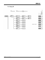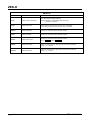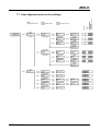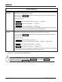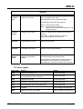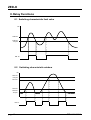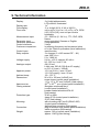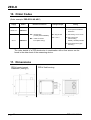
1
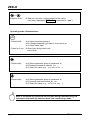
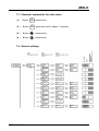
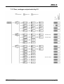
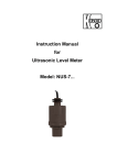
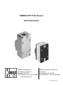
KOBOLD DFT Flow Sensor
User Instructions
KOBOLD Instruments Inc.
KOBOLD Instruments Canada Inc.
1801 Parkway View Drive
9A Aviation
Pittsburgh, PA 15205
Pointe-Claire, QC H9R 4Z2
(412) 788-2830 • Fax (412)-788-4890 (514) 428-8090 • Fax (514) 428-8899
www.koboldusa.com
DFT_manual_3-14
DFT
Table Of Contents
KOBOLD DFT FLOW SENSOR
1.0
General . . . . . . . . . . . . . . . . . . . . . . . . . . . . . . . . . . . . . . . . . . . . . . . . . . . . 1
2.0
Specifications. . . . . . . . . . . . . . . . . . . . . . . . . . . . . . . . . . . . . . . . . . . . . . . . 2
3.0
4.0
2.1
Mechanical Data. . . . . . . . . . . . . . . . . . . . . . . . . . . . . . . . . . . . . . . . . 2
2.2
Electrical Data. . . . . . . . . . . . . . . . . . . . . . . . . . . . . . . . . . . . . . . . . . . 2
Installation Instructions. . . . . . . . . . . . . . . . . . . . . . . . . . . . . . . . . . . . . . . . . 3
3.1
Electrical Installation. . . . . . . . . . . . . . . . . . . . . . . . . . . . . . . . . . . . . . 3
3.2
Mechanical Installation. . . . . . . . . . . . . . . . . . . . . . . . . . . . . . . . . . . . 4
Operation . . . . . . . . . . . . . . . . . . . . . . . . . . . . . . . . . . . . . . . . . . . . . . . . . . . 5
4.1
DFT w/Pulse Output. . . . . . . . . . . . . . . . . . . . . . . . . . . . . . . . . . . . . . 6
4.2
DFT w/Analog Output ........ . . . . . . . . . .. . . . . . . . . . . . . . . . . . . . . . 6
4.3
DFT w/Electronic Controller:.. . . . . . . . .. . . . . . . . . . . . . . . . . . . . . . 7
5.0
Arrival of Damaged Equipment . . . . . . . . . . . . . . . . . . . . . . . . . . . . . . . . . . 7
6.0
Maintenance. . . . . . . . . . . . . . . . . . . . . . . . . . . . . . . . . . . . . . . . . . . . . . . . . 7
7.0
Need Help With Your DFT Flowmeter?. . . . . . . . . . . . . . . . . . . . . . . . . . . . . 7
Cautions and Warnings:. . . . . . . . . . . . . . . . . . . . . . . . . . . . . . . . . . . . . . . . . . . . . . 9
PDF Rev. 3/14
DFT
KOBOLD DFT FLOW SENSOR
User Instructions
CAUTION:
1.0
For safety reasons, please read the cautionary information located at
the end of the manual, before attempting installation.
General
The KOBOLD DFT is intended for use in applications where flow measurement is
desired and the pulse output signal is to be transmitted to a remote location. The
available 4-20 mA current outputs also allow for an output signal to be transmitted to a
remote location conveniently. The optional electronic controllers allow the flow rate data
to be indicated locally and have various capabilities such as batching and control
switching in addition to an analog output for remote data collection or display.
The DFT uses a paddle wheel to meter flow. The principle of operation is quite simple;
the paddle wheel rotation is calibrated for flow rate. This rotation-flow relationship is
linear in theory. In practice, theory is nearly borne out, leading to a very precise
measuring device. Any non-linearity is within the stated measurement error of the
device.
The paddle wheel approach to flow measurement has the advantage that the instrument
may be installed in any orientation; only the flow direction is specified. Further, this
measurement technique is relatively insensitive to small debris in the medium (ferritic
contaminants, however, must be avoided).
PDF Rev. 3/14
DFT
2.0
2
Specifications
Table 2.1: Mechanical Data
Flow Range:
0.05-0.30 GPM to 0.5-12 GPM
Accuracy:
+/- 2.5% of Full Scale
Media:
Water and other low-viscosity liquids
Maximum Pressure:
Brass Body: 230 PSIG
PTFE Body: 70 PSIG
Temperature Range:
-4 to 176°F
Wetted Materials:
Brass Body:
PTFE body:
Brass/Ceramic (or Brass/Sapphire), POM, NBR
PTFE/Ceramic or PTFE/Sapphire
Table 2.2: Electrical Data
with OEM Pulse Flow Transmitter
Power Supply:
5-24 VDC, 10 mA Maximum
Output Type:
NPN, Open Collector, 0-100 Hz Nominal
Electrical Connection:
DIN 43650 Plug
Environmental Protection:
IP65 (equivalent to NEMA 4)
with Electronic Controllers (See appropriate ZED manual))
PDF Rev. 3/14
3
3.0
DFT
Installation Instructions
CAUTION:
3.1
For safety reasons, please read the cautionary information located at
the end of the manual, before attempting installation.
Electrical Installation
3.1.1 Make sure that the actual flow rate in your system lies within the flow
range of the instrument. Flow rates in excess of 120% of the unit’s
maximum range will, in continuous use, lead to bearing and/or paddle
wheel damage.
3.1.2 Ensure that the power supply voltage is in accordance with that
specified on the identification tag.
3.1.3 DFT w/OEM Pulse Output: If the sensor is to be used to provide a
voltage pulse output, a sourcing output pull-up resistor MUST be
connected between the supply voltage terminal and the open collector
output terminal (terminals 1 and 3). This resistor should be sized such that
the collector to emitter current is nominally 8 mA during the transistor “On”
state. Under no circumstances should the collector to emitter current be
allowed to exceed 10 mA. Electrical connections are made using the
standard DIN 43650 plug as specified by the following wiring diagram:
Diagram 3.1; OEM NPN Pulse Output Wiring
R pull-up =
V supply
.008
ohms
PDF Rev. 3/14
DFT
4
3.1.4 DFT w/Controller:
Please refer to the appropriate ZED display/controller manual provided
separately.
3.1.5 DFT w/PNP Pulse or Analog Output:
Please refer to the appropriate connection information as noted on the label of
the device.
3.2
Mechanical Installation
3.2.1 The flow direction is indicated by an arrow on the housing. Install
the instrument with the arrows aligned with the flow direction in your pipes.
The flow sensor may be mounted in any orientation, as long as the axle
remains in a horizontal plane.
3.2.2 Connect the unit with appropriately sized fittings. Take care not to
place stresses on the housing. Use a wrench to hold the instrument static
while you tighten the fittings on your pipe.
3.2.3 Should there be small amounts of ferrite contaminants in the
medium, we recommend the installation of our magnetic filter (type MFRor equivalent).
3.2.4 Medium should be introduced to the system slowly to avoid pressure
surges which could damage the instrument.
PDF Rev. 3/14
5
4.0
DFT
Operation
4.1
DFT w/Pulse Output:
The device is delivered with a label noting the output frequency at maximum
flow. You must use this infomation to calculate a "k-factor" to enter into your
display device to determine the rate of flow in your system. Modification of the
sensor (by physically modifying or replacing sensor components due to wear)
requires factory recalibration of the unit if the design accuracy is to be
maintained.
4.1.1 Turning the Unit On
The sensor is operational as soon as it is wired into a power supply.
4.1.2 Flow Measurement with pulse putput
A frequency counting device must be used to read the sensor output and
convert that measurement to rate of flow (the flowmeter output frequency
is directly proportional to flow). The sensor “k-factor” (calculated
previously) is the number of pulses the sensor generates per gallon of
water flow through the sensor and is used to properly scale the display. .
4.2
DFT w/Analog Output:
The device is delivered fully calibrated and ready for use. Remember that a zero flow or
"no flow" condition provides a 4 mA output while a 20 mA output is produced at the
maximum flow point of the unit's range. The output is linear (directly proportional) with
flow within the typical stated accuracy limits of the device.
4.3
DFT w/Electronic Controller:
The device is delivered fully calibrated and ready for use. Please refer to the appropriate
ZED display/controller manual provided seperately.
PDF Rev. 3/14
DFT
PDF Rev. 3/14
6
7
5.0
DFT
Arrival of Damaged Equipment
Your instrument was inspected prior to shipment and found to be defect-free. If damage
is visible on the unit, we advise that you carefully inspect the packing in which it was
delivered. If damage is visible, notify your local carrier at once, since the carrier is liable
for a replacement under these circumstances. If your claim is refused, please contact
Kobold Instruments for further advisement.
6.0
Maintenance
The KOBOLD DFT requires little maintenance provided the measured medium is kept
free of contaminants. In particular, ferritic pollutants can cause problems for this device
due to the incorporation of magnets into the paddle wheel. To avoid this, we recommend
the installation of a magnetic filter, such as Kobold's model MFR or equivalent.
Do NOT tamper with the electronics as this voids your warranty.
7.0
Need help with your DFT Flowmeter?
Call one of our friendly engineers at 412-788-2830.
PDF Rev. 3/14
DFT
PDF Rev. 3/14
8
9
DFT
Caution
PLEASE READ THE FOLLOWING GENERAL FLOW METER / MONITOR
WARNINGS BEFORE ATTEMPTING INSTALLATION OF YOUR NEW
DEVICE. FAILURE TO HEED THE INFORMATION HEREIN MAY
RESULT IN EQUIPMENT FAILURE AND POSSIBLE SUBSEQUENT
PERSONAL INJURY.
PDF Rev. 3/14
DFT
10
•
User's Responsibility for Safety: KOBOLD manufactures a wide range of
process sensors and technologies. While each of these technologies are
designed to operate in a wide variety of applications, it is the user's
responsibility to select a technology that is appropriate for the application,
to install it properly, to perform tests of the installed system, and to maintain
all components. The failure to do so could result in property damage or
serious injury.
•
Inspect instrument for damage upon arrival: Cracked, fractured, bent or
otherwise damaged instruments must not be put into use, since the device
is weakened to an unknown extent. Refer to Section 5.0, Arrival of
Damaged Equipment, for additional information.
•
Media and Chemical Compatibility: The maximum tolerances of the
device have been determined using water. If using other media, especially
corrosive media, it is critically important that the user determine chemical
compatibility with our instruments. KOBOLD Instruments Inc. cannot
accept responsibility for failure and consequences resulting from use of
media other than water.
•
Material Compatibility: Make sure that the model which you have
selected is chemically compatible with the application liquids. While the
meter is liquid and spray resistant when installed properly, it is not
designed to be immersed.
•
Proper Installation in Flow System: Install the device in a fully supported
position within your flow system. This avoids excessive stresses which may
damage the instrument. In particular:
a.) Ensure that the plumbing leading to and from the instrument is fully
supported and that the instrument does not perform the physical function of
a joint.
b.) When calculating stress on the device caused by plumbing, the weight
of the medium in the pipes must be considered as well.
c.) Misaligned runs of rigid piping can cause large stresses when
connected to the instrument. Do not connect in such a fashion.
d.) When connecting fittings, hold the instrument fittings rigid with a
correctly sized wrench. Do not install by twisting the instrument into the
pipe fittings.
e.) Do NOT install by holding the device housing to provide counter-torque
to the pipe fitting.
f.) Use an appropriate amount of PTFE tape on male threads of fitting.
This reduces the twisting stresses produced by tightening the fittings into
each other.
g.) Do not use pliers or wrenches on the housing, as this may damage it.
h.) Do not overtighten, as this may fracture the fittings.
PDF Rev. 3/14
11
•
DFT
While Operating the Flow System: During operation, there are a number
of situations to avoid:
a.) The sudden cessation of fluid flow causes what is typically referred to
as "water hammer". Most people are familiar with this phenomenon from
their home experience - it is the cause behind the loud clank of water pipes
which occurs when faucets are turned off too suddenly. The cause behind
this "water hammer" is quite easy to visualize. Water is fairly massive. The
amount of water in long runs of pipe is quite substantial. When the faucets
are turned off suddenly, especially from a full on condition, the water has
considerable momentum and does not want to stop flowing. The situation
is similar to stopping a car by running into a wall, rather than by applying
brakes. Both are sudden rather than gradual. The damage to the wall can
be substantial (not to mention the car).
b.) The "water hammer" causes surges in fluid pressure which could cause
the measurement instrument's pressure limit to be exceeded, resulting in
failure and possible personal injury.
c.) Fluid surges, as well as the water hammer, can be particularly
damaging to empty flowmeters since there is no back pressure in the
device. The damage is caused, once again, by momentary excess
pressure. To avoid these surges, fluid lines should remain full (if possible)
and water flow should be introduced to the device slowly.
d.) If the instrument is isolated with inlet and outlet valves, the flowmeter
must be completely drained when said valves are both closed. Failure to do
so could result in damage to the device caused by thermal expansion of
fluid.
e.) Freezing of water in the instrument must be avoided since the resultant
expansion will damage the flowmeter and make it unsafe for use.
•
Wiring and Electrical: Section 2.0, Specifications and Section 3.0,
Installation Instructions, provide the voltage and current limitations and the
wiring for the various sensor types. The sensor electrical ratings should
never be exceeded. Electrical wiring of the sensor should be performed in
accordance with all applicable national, state and local codes.
•
Temperature and Pressure: Section 2.0, Specifications, provides the
temperature and pressure limits for each model. Operation outside these
limitations will cause damage to the unit and can potentially cause personal
injury. Fluid should never be allowed to freeze inside the sensor.
•
Make a Fail-safe System: Design a fail-safe system that accommodates
the possibility of switch or power failure. In critical applications, KOBOLD
recommends the use of redundant backup systems and alarms in addition
to the primary system.
PDF Rev. 3/14
Operating Instructions
for
Evaluation Electronics
Model: ZED-K
and DF-…KLxxx
ZED-K
1. Contents
1.
2.
3.
4.
5.
6.
Contents ........................................................................................................ 2
Note .............................................................................................................. 3
Instrument Inspection .................................................................................... 3
Regulation Use.............................................................................................. 3
Operating Principle........................................................................................ 4
Electrical Connection .................................................................................... 5
6.1 ZED-K field housing and control panel installation ............................... 5
6.2 DF-…KLxxx, cable connection ............................................................. 5
6.3 Connection example ............................................................................ 6
7. Operation and Menu Structure ...................................................................... 7
7.1 General ................................................................................................ 7
7.2 Function of the control keys ................................................................. 7
7.3 Character explanation for main menu .................................................. 9
7.4 General settings ................................................................................... 9
7.5 Flow, analogue output and relay S1 .................................................. 11
7.6 Relay S2 ............................................................................................ 13
7.7 User alignment and service-settings .................................................. 15
7.8 Error report ........................................................................................ 17
8. Relay Functions .......................................................................................... 18
8.1 Switching characteristic limit value .................................................... 18
8.2 Switching characteristic window ........................................................ 18
9. Technical Information .................................................................................. 19
10. Order Codes ............................................................................................... 20
11. Dimensions ................................................................................................. 20
12. Declaration of Conformance ....................................................................... 21
Manufactured and sold by:
Kobold Messring GmbH
Nordring 22-24
D-65719 Hofheim
Tel.: +49(0)6192-2990
Fax: +49(0)6192-23398
E-Mail: [email protected]
Internet: www.kobold.com
page 2
ZED-K K04/0310
ZED-K
2. Note
Please read these operating instructions before unpacking and putting the unit
into operation. Follow the instructions precisely as described herein.
The devices are only to be used, maintained and serviced by persons familiar
with these operating instructions and in accordance with local regulations
applying to Health & Safety and prevention of accidents.
When used in machines, the measuring unit should be used only when the
machines fulfil the EWG-machine guidelines.
3. Instrument Inspection
Instruments are inspected before shipping and sent out in perfect condition.
Should damage to a device be visible, we recommend a thorough inspection of
the delivery packaging. In case of damage, please inform your parcel service /
forwarding agent immediately, since they are responsible for damages during
transit.
Scope of delivery:
The standard delivery includes:
• Electronics for measuring and monitoring
• Operating Instructions
model: ZED-K and DF-…KLxxx
4. Regulation Use
Any use of the Evaluation Electronics, model: ZED-K and DF-..KLxxx, which
exceeds the manufacturer’s specification may invalidate its warranty. Therefore,
any resulting damage is not the responsibility of the manufacturer. The user
assumes all risk for such usage.
ZED-K K04/0310
page 3
ZED-K
5. Operating Principle
The evaluation unit changes the frequency signal of the pickup into a flow
reading and into a scalable analogue signal.
The top display line of the double-spaced display shows the flow value with
measuring unit and the bottom line a bargraph indicator proportional to the
measuring value.
The two relays with floating output changeover contacts continuously monitor
the flow values. Switching point, hysteresis, a window point, and switch on or off
delay can be set separately for each relay. The switching points can also be set
directly by using the control keys without having to change over into the menu. A
red LED indicates the switching status.
The analogue output is optionally available as current output with 0(4)...20 mA
or as voltage output with 0...10 V. The menu languages can be switched
between German or English. If used where the flow readings change rapidly, the
display can be pacified and the analogue reading averaged by switching on
some software.
A MIN/MAX reading memory determines the extreme readings of the flow. The
display of the readings and the resetting are achieved by using the keys without
having to change into the menu. Resetting by using the keys can also be
blocked.
The set parameters can be protected against unauthorized alteration by using a
password function.
page 4
ZED-K K04/0310
ZED-K
6. Electrical Connection
6.1 ZED-K field housing and control panel installation
PNP
Namur
GND
F-Input
Ana
Out
d.c.*)
GND
d.c.*)
GND
Sensor supply
GND
0-10 VDC
0-20 mA
NPN
14
13
12
11
10
9
8
7
6
5
4
3
2
1
Power
supply
8
7
6
5
4
3
2
1
S2
S1
- or AC
+ or AC
*) Don’t connect the clamp!
6.2 DF-…KLxxx, cable connection
Wire number
1
2
3
4
5
6
7
8
9
10
ZED-K electronics
+24 VDC
GND
4-20 mA / 0-10 V
GND
S1 N/O
S1 COM
S1 N/C
S2 N/O
S2 COM
S2 N/C
*) Don’t connect the wire!
ZED-K K04/0310
page 5
ZED-K
6.3 Connection example
PNP-Sensor
NPN-Sensor
Namur-Sensor
page 6
ZED-K K04/0310
ZED-K
7. Operation and Menu Structure
7.1 General
Only the menu items of which the lines are marked in the selection matrix (in the
right position) in grey colour, are available in the respective instrument version.
Italic written values in the menu structure are blinking in the display, if
they have been chosen for any input.
The parameter can only be changed, if the security code has been
entered correctly! The message „locked“ will appear if the input has
not been activated.
7.2 Function of the control keys
Operating mode >Measure< :
PGM
ENTER
- Press briefly:
Æ a) Display total quantity, then
Display corresponding scale unit or
Æ b) Reset status reports.
- Press for 3 sec: Æ Switch to operating mode >Parameterise<.
- Press briefly:
Æ Display min. flow value (MIN value memory).
- Press for 3 sec: Æ Enter switching point for Relay S1 s1SPoint
(only if parameter SPdirect is set to “yes”).
- Press briefly:
Æ Display max. flow value (MAX value memory).
- Press for 3 sec: Æ Enter switching point for Relay S2 s2SPoint
(only when parameter SPdirect is switched to “yes”).
ZED-K K04/0310
page 7
ZED-K
+
Press for 3 sec:
Æ Sets min. and max. value memory to flow value
(only when parameter fMMReDir is switched to “yes”).
Operating mode >Parameterize<:
PGM
ENTER
- Press briefly:
Æ a) Open parameter group or
Æ b) Change parameter (go lower in menu level) or
Æ c) Adopt value input.
- Press for 3 sec: Æ Abort input and go back one
menu level.
- Press briefly:
Æ a) Select parameter group or parameter or
Æ b) Reduce selected number by 1 or
Æ c) Select list value (e.g.... L/m, L/h, m3/m, ...).
- Press briefly:
Æ a) Select parameter group or parameter or
Æ b) Increase selected number by 1 or
Æ c) Select list value (e.g.... m3/m, L/h, L/m, ...).
Note: If no button is pressed for 20 seconds during parameterising, the
instrument automatically switches back into >measuring< mode.
page 8
ZED-K K04/0310
ZED-K
7.3 Character explanation for main menu
( e ) - Button
( E ) - Button
PGM
ENTER
PGM
ENTER
press shortly.
press and hold for approx. 3 seconds.
(▼ ) - Button
press shortly.
(▲ ) - Button
press shortly.
7.4 General settings
ZED-K K04/0310
page 9
ZED-K
GENERAL SETTINGS
Menu Item
Parameter / Function
Explanation / Values / Other
Language
Select menu language
German or English
fUnitFS *
Measuring unit for flow
measurement
mL/s, mL/m, L/s, L/m, L/h, m /m, m /h,
GPM, GPH, UU/s, UU/m, UU/h
fValueFS *
Maximum measuring range value
for flow measurement
Range = 0,00...99,9..._100...9999
fMinVal *
Minimum measuring range value
for flow measurement
fPls/rev*
Impulse per sensor wheel
revolution
Number of impulses per revolution of the sensor wheel or the like
Necessary for long-term period averaging if the readings per revolution vary.
The function is switched off when the input value is 1.
fJumpVD*
Flow switch value for attenuation
cut-off
Value in %, basis is fValueFS and fUnitFS.
Attenuation does not function if the switch value is 0%.
fOverflV *
Flow overflow value (overflow)
Value in %, basis is fValueFS and fUnitFS.
If exceeded, an M100 report is generated and faded in, alternating
with the flow indicator.
The report is saved and can be reset by briefly pressing the
PGM key.
fFactor
Select pulse ration
Selection of works calibration or user calibration.
(only for devices Model DF-...ZLxxx and Model-...ExxR)
UserUnit.
Special volume unit
Customer-specific special unit UU.
The value entered corresponds to the number of litres of the special unit, e.g.
in the case of the unit Barrel the factor would for example be 115.6271.
SPdirect
Activation of direct input switching
point
3
3
Basis is fValueFS and fUnitFS
If the level drops below this, the flow indicator goes to 0.
yes: Direct input of switching points s1SPoint and
s2SPoint is possible using the keys (default).
no: The switching points can only be set in the menu .
*)
Only for ZED devices: Device-specific parameter, is only visible after activation in the SecCode menu item in the SERVICE
menu group, and can be changed.
page 10
ZED-K K04/0310
ZED-K
7.5 Flow, analogue output and relay S1
ZED-K K04/0310
page 11
ZED-K
FLOW
Menu Item
Parameter / Function
Explanation / Values / Other
3
fUnit
fDamping
fMMReDir
3
mL/s, mL/m, L/s, L/m, L/h, m /m, m /h,
GPM, GPH, UU/s, UU/m, UU/h
Unit of flow indicator
Attenuation of reading fluctuations in the flow indicator
Reset the Min/Max flow value directly using the keys,
without using the menu
The attenuation pacifies the flow indicator.
The attenuation value is the approximate equivalent of the setting time
of the display value to c. 90% of a measured value jump in seconds.
(Parameter is blocked at DF-...ZLxxx devices).
yes: direct resetting of the Min/Max value memory by simultaneously
pressing (3 sec) the (+) and (-) keys (default).
no: memory reset only possible with fMMRST.
fMMRST
Menu Item
Reset the Min/Max flow value memory of the flow
indicator
yes: Resets Min / Max value memory for the flow
no: No action.
ANALOGUE OUTPUT
Parameter / Function
Explanation / Values / Other
aLIFE 0
Select Life Zero
Offset at power output: 0 mA or 4 mA
at 0-10 V ≙ 0 mA → 0 V and 4 mA → 2 V
aLowFlow
Flow reading at 0/4 mA or 0/2 V
Lower flow reading of gauged output range,
value has the same unit as the flow indicator
aHighFlo
Flow reading at 20 mA or 10 V
Upper flow reading of gauged output range,
value has the same unit as the flow indicator
RELAY S1
Menu Item
Parameter / Function
Explanation / Values / Other
s1Char.
Relay1 Switch characteristic
Limit: Monitoring a reading (s1SPoint).
Window: Monitoring an adjustable measuring range
(s1SPoint...s1Fpunkt).
s1Logic
Relay1 Switch logic
normal: Relay 1 activated when the limit value is exceeded.
invers: Relay 1 drops out when the limit value is exceeded.
s1SPoint
Relay1 Switchpoint
Reading is in the same units as the flow indicator.
s1Hyste
Relay1 Hysteresis
Reading is in the same units as the flow indicator.
s1FPoint
Relay1 Windowpoint
Reading is in the same units as the flow indicator.
(only if s1Char. is set to Window )
s1SDelay
Relay1 Switch delay
Delays the switching of the relay when the limit value is exceeded.
Range:_ 0,0...99,9 sec
s1RDelay
Relay1 Reset delay
Delays the switching of the relay when the limit value is undershot.
Range:_ 0,0...99,9 sec
page 12
ZED-K K04/0310
ZED-K
7.6 Relay S2
ZED-K K04/0310
page 13
ZED-K
RELAY S2
Menu Item
Parameter / Function
Explanation / Values / Other
s2Char.
Relay2 Switch characteristic
Limit: Monitoring a reading (s2SPoint).
Window: Monitoring an adjustable measuring range
(s2SPoint...s12punkt).
s2Logic
Relay2 Switch logic
normal: Relay 2 activated when the limit value is exceeded.
invers: Relay 2 drops out when the limit value is exceeded.
s2SPoint
Relay2 Switchpoint
Reading is in the same units as the flow indicator.
s2Hyste
Relay2 Hysteresis
Reading is in the same units as the flow indicator.
s2FPoint
Relay2 Window point
Reading is in the same units as the flow indicator.
(only if s2Char. Is set to Window )
s2SDelay
Relay2 Switch delay
Delays the switching of the relay when the limit value is exceeded.
Range:_ 0,0...99,9 sec
s2RDelay
Relay2 Reset delay
Delays the switching of the relay when the limit value is undershot.
Range:_ 0,0...99,9 sec
page 14
ZED-K K04/0310
ZED-K
7.7 User alignment and service-settings
ZED-K K04/0310
page 15
ZED-K
USER CALIBRATION
Menu Item
CAL Freq*
Function / Description
Calibrate by entering frequency and flow.
In the menu item CAL Freq the bottom line always shows the current pulse value of the
User calibration.
Calibration process:
a) FlowVal Enter nominal flow value of the sensor. > (e) press >
b) FlowUnit Enter unit for flow value. > (e) press >
c) Freq.Val. Enter nominal frequency > finish with (e).
The new pulse value of the User calibration is calculated from these three values and saved
as user calibration for the flow measurement, e.g. 20.2757 pls./litre.
CAL Vol.
Calibration process using impulse counting and volume input (cc procedure).
In the menu item CAL Vol. the bottom line always shows the current pulse value of the
User calibration.
Calibration process:
a) PulseCnt measures number of impulses
(e) press > start counter (impulses are counted) > (e) press > stops counter.
b) Vol.Val Enter measured volume value > (e) press.
c) Vol.Unit Enter unit for volume value > finish with (e).
The pulse value of the User calibration is calculated from these three values and is saved as
the user calibration for the flow measurement, e.g. 3900,5 pls./L.
*) CAL Freq – Only possible with ZED devices.
Note: With ZED devices it is necessary to enable the device-specific
parameter input in the menu Item SecCode in the menu SERVICE in
order to activate the CAL-USER function.
page 16
ZED-K K04/0310
ZED-K
SERVICE
Menu Item
SecCode
Input
Function
Explanation / Values / Other
Enter security code
Input of 4-digit security code
and enablement of the parameter change.
The following codes have been defined:
3461 – General menu release
6571 – Activates the device-specific
parameters (only ZED and measuring unit as
compact version)
SecCode
change
Change security code
Define or change security code for the first time or
change.
If no code ( = 0000) has been set, then the
parameter values set are unsecured!
Save Prm
Save parameter record
Save current settings
Load Prm
Load parameter record
Restore saved settings (reload).
Restore
Default
Reset to works default
settings
Load initial setting with password 2541.
ATTENTION: For ZED-devices the device-specific
parameters will be overwritten. An adjustment
provided by the customer will be lost in the process.
7.8 Error report
Error code
E102
Reason
User unit may not be ≤ 0
Reset
Correct parameter
E142
Distance between upper and lower analogue value
too small (based on the actual flow)
Correct parameter
E162
Hysteresis too large
Correct parameter
E242
Frequency must be between 0,2 and 2000 Hz
Correct parameter
E245
Calculated pulse value out of valid range
Correct parameter
M100
Overflow
Acknowledge with PGM button
####
Value does not fit in the display
Choose suitable measuring unit
ZED-K K04/0310
page 17
ZED-K
8. Relay Functions
8.1 Switching characteristic limit value
MV
sxSPoint
sxSPoint
- sxHyste
REL Sx
8.2 Switching characteristic window
MV
sxFPoint
+ sxHyste
sxFPoint
sxSPoint
sxSPoint
- sxHyste
REL Sx
page 18
ZED-K K04/0310
ZED-K
9. Technical Information
Display:
Display rate:
Flow display:
Flow units:
Measurement input:
Parameter input:
Parameter protection:
Control elements:
Customer comparison:
Control input:
Relay outputs:
Voltage supply:
Analogue output:
Apparent power:
Ambient temp.:
Dimensions:
Aperture size:
Casing material:
Protection type:
Mounting:
Connection:
Weight:
ZED-K K04/0310
2 x 8-digit alphanumeric,
LCD module, illuminated
1 s-1
3- or 4-digit (XX.X, X.XX or XXXX)
mL/s, mL/m, L/s, L/m, L/h, m3/m, m3/h, GPM
(US), GPH (US), user unit per h/min/s
selectable
0.2...2000 Hz (5...24 VDC), TTL, PNP, NPN,
Namur
menu controlled, German or English
4-digit password
3 keys
by entering frequency and measured value
or in the Teach-In procedure (level calibration)
reset-function
2 x changer (2 x N/O contact DF-…KL)
max. 250 VAC/DC
5 A / 1000 VA
24 VDC ± 20 %, approx. 80 mA or
90...250 VAC / max. 3 VA
0(4)-20 mA
Load: max. 500 Ω (300 Ω at AC-supply)
or 0-10 V (Load: > 100kΩ)
15 V (at 24 VDC) / max. 50 mA
12 V (AC-supply) / max. 50 mA
-20...+70 °C
96 x 96 x 109 mm (LxWxD) incl.
screw clamp (control panel installation)
117 x 117 x 127 mm (LxWxD) (field casing)
92+0.8 x 92+0.8 mm (control panel installation)
fibreglass reinforced Noryl,
(control panel installation)
powder coated aluminium/PA 66
(field casing)
IP 40 on front
clamp IP 00 (control panel installation)
IP 65 (field casing)
with mounting clip Form B (DIN 43 835)
(control panel installation)
wall and pipe mounting (field casing)
plug-in terminal strip (control panel installation)
cable connection (field casing)
approx. 360 g (control panel installation)
approx. 1240 g (field casing)
page 19
ZED-K
10. Order Codes
(Order example: ZED-ZF10 KS 4R P)
Supply
Model
90-250 VAC
ZED-KF10
Electrical connection
ZED-KF13
Casing
P = control panel installation
96x96 mm
KS = terminal strip
(control panel installation)
24 VDC
Analogue output
MS = cable connection
M 18 (field casing)
4R = 0(A)-20 mA
1 R = 0-10 V
F = field casing 116 x116 mm
S = field casing with
wall mounting,
infinitely variable pivotable
R = field casing with 2”-pipe
mounting
The order details of a ZED electronics in combination with a flow sensor can be
found in the data sheet of the measuring device.
11. Dimensions
ZED-K control panel
installation (casing P)
page 20
ZED-K field housing
ZED-K K04/0310
ZED-K
12. Declaration of Conformance
We, KOBOLD Messring GmbH, Hofheim-Ts, Germany, declare under our sole
responsibility that the product:
Evaluation Electronics
Model: ZED-K and model: DF-…KLxxx
to which this declaration relates is in conformity with the standards noted below:
EN 61326-1
2006-10
Electrical equipment for control and instrumentation technology and laboratory
use – EMC-requirements (industrial area)
DIN EN 61010-1
2002-08
Safety requirements for electrical
instruments.
measuring-,
control-
and
laboratory
EN 60529, DIN VDE 0470-1
1992-11
Protection type housing (IP-Code)
Also the following EEC guidelines are fulfilled:
2004/108EC
2006/95 EC
EMC Directive
Low Voltage Directive
Hofheim, 22. April. 2008
H. Peters
General Manager
ZED-K K04/0310
M. Wenzel
Proxy Holder
page 21