1
HAND-HELD
CAPNOGRAPHY
Service Manual
Model 615
Mar 23, 2000
Catalog No. 9425-90-00
Novametrix Medical Systems Inc.
5 Technology Drive
Wallingford, Connecticut, U.S.A. 06492.
About This Manual
About This Manual
This manual is intended for use by technical personnel for servicing the Model 615. Refer to the
Model 615 User’s Manual (Cat. No. 9425-23) for detailed information on normal operation.
TIDAL WAVE and CAPNOSTA ® are registered trademarks. Cidex is a trademark of Arbook,
Inc. Nafion is a registered trademark of Dow Corning Corp. The Model 615 is Year 2000
compliant.
Copyright 2000 Novametrix Medical Systems Inc. This document contains information which
is proprietary and the property of Novametrix Medical Systems Inc., and may not be
reproduced, stored in a retrieval system, translated, transcribed or transmitted in any form, or by
any means, without prior explicit written permission from Novametrix Medical Systems Inc.
Revision Histor
23-Mar-00
Release, revision 00
Declaration of Conformity with European Union Directives
The authorized representative for Novametrix Equipment is:
European Compliance Services Limited
Oakdene House
Oak Road
Watchfield
Swindon, Wilts SN6 8TD
UK
Manufacturing, Quality and Safety
Novametrix manufacturing facility is certified to ISO 9001 and EN46001 (MDD93/42/EE
Annex II). Novametrix Medical Systems Inc. products bear the “CE 0086” mark. The product
is certified by Underwriter’s Laboratories (UL) to bear the UL mark; and tested by TUV
Rheinland to IEC601-1 / EN60601-1.
Rev. 00
Model 615 Service Manual
iii
Manufacturing, Quality and Safety
[This page intentionally blank.]
iv Model 615 Service Manual
Rev. 00
Contents
General Description .....................................................................................................1
Indication for use .........................................................................................................1
Keypanel Controls and Indicators ...............................................................................1
Connections and Labeling ...........................................................................................3
Principle of operation ..................................................................................................3
Safety .............................................................................................................................4
Theory of Operation .....................................................................................................7
Digital Control System .................................................................................................7
Background Mode Debugging .........................................................................11
System Memory ...............................................................................................11
Serial Communications ....................................................................................12
User Interface Control Circuitry .......................................................................12
Real Time Clock, Power on RESET Generation and Glue Logic ....................13
CO2 System Analog Subsections .............................................................................13
CO2 Source Drive ............................................................................................13
CAPNOSTAT® CO2 sensor Case and Detector Heater Control ....................15
CO2 Input Signal Path .....................................................................................16
CAPNOSTAT® CO2 sensor Interface .............................................................16
Barometric Pressure Circuitry ..........................................................................16
Sampling Pump ...............................................................................................17
Digital and Analog Control Lines .....................................................................17
Power Supply and Battery Charger ...........................................................................18
Supply and Reference Voltage Generation .....................................................18
Battery Charger Circuitry .................................................................................20
Functional Tests .........................................................................................................23
Equipment Required .................................................................................................23
Procedure ..................................................................................................................23
Power up .........................................................................................................23
Capnography Tests .........................................................................................24
Sidestream Tests .............................................................................................25
Miscellaneous Tests ........................................................................................25
Accuracy Tests ...........................................................................................................27
Equipment Required .................................................................................................27
Procedure ..................................................................................................................27
Electronic Tests ..........................................................................................................31
Equipment Required .................................................................................................31
Test Procedure ..........................................................................................................31
Safety Testing ...........................................................................................................34
Status Messages ........................................................................................................35
System Messages .....................................................................................................35
Capnography Messages ...........................................................................................35
Maintenance ................................................................................................................37
General ....................................................................................................................37
Rev. 00
Model 615 Sevice Manual
v
Contents
Maintenance Schedules ............................................................................................ 37
Cleaning and Sterilization ......................................................................................... 38
Monitor, BaseStation and External Power Supply .......................................... 38
CAPNOSTAT® CO2 Sensor ........................................................................... 38
Single Patient Use Airway Adapters ............................................................... 38
External Sampling System Components ......................................................... 38
Internal Sampling System Components .......................................................... 38
Battery Maintenance ................................................................................................. 39
AC/Battery Operation ...................................................................................... 39
Battery Status and Alerts ................................................................................ 40
Removing and Installing the Battery ............................................................... 41
Charge using External Power Supply ............................................................. 41
Charge using optional BaseStation ................................................................. 42
Charging with External Charger ...................................................................... 42
AA Lithium Batteries ........................................................................................ 43
Battery Life and Recharge Times .................................................................... 44
Assembly Exchanges ................................................................................................ 44
Disassembling the Monitor .............................................................................. 44
Reassembling the monitor .............................................................................. 47
Serial Communications/Power Interface Connector ................................................. 47
Software Update Instructions .................................................................................... 48
Equipment Required ....................................................................................... 48
Setup ...............................................................................................................48
Procedure ........................................................................................................ 48
Specifications ............................................................................................................. 53
Specifications ............................................................................................................ 53
General ........................................................................................................... 53
Capnograph .................................................................................................... 53
EtCO2 Section (Mainstream) .......................................................................... 53
Respiratory Rate (Mainstream) ....................................................................... 53
EtCO2 Section (Sidestream) ........................................................................... 54
Respiratory Rate (Sidestream) ........................................................................ 54
Monitor Specifications ............................................................................................... 54
Additional Features ......................................................................................... 55
Accessories ................................................................................................................ 57
vi Model 615 Service Manual
Rev. 00
Section 1
General Description
Section 1
General Description
1.1 Indication for use
The Model 615 hand-held, portable Capnograph is intended to be used for monitoring end tidal
CO2 and respiration rate in monitoring environments such as ventilatory support, emergency
and anesthesia. The Model 615 incorporates a miniature vacuum pump to draw expired
respiratory gases through the CAPNOSTAT® CO2 Sensor using a sampling airway adapter and
nasal cannula. The Model 615 is designed to monitor adult, pediatric and neonatal patients and
is not intended for any other purpose.
NOTE
Components of this product and its associated accessories which have patient contact are
free of latex.
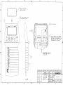
1.2 Keypanel Controls and Indicators
Page key
Display screen
Power key
Alert key
Backlight key
Battery charge indicator
and LED
Adapter key
AC indicator
Alert LED
Switches power on/off.
Displays, Capnogram, EtCO2 trend or respiration rate trend. Press and hold to
enter the PRINT SELECTION menu.
Sets 2 minute silence and displays the SET ALERTS menu. Press and hold for
3 seconds to disable audible alerts. Press and hold again to cancel.
The Alert Key LED:
Steady yellow: audio silenced for 2 min., no alert in progress.
Flashing yellow: audio off , no alert in progress.
Flashing red and yellow: alert in progress; audio is off or 2 minute silence.
Rev. 00
Model 615 Service Manua
1
Section 1
General Description
Press to set adapter type. Press and hold for 4 seconds to zero adapter.
Press to turn backlight on/off, or press and hold to adjust contrast.
INDICATORS
Illuminates when on battery power. Green; battery is fully charged, slow flashing yellow; battery power is low (approximately 20 minutes of operation), Fast
flashing red; battery is exhausted (approximately 5 minutes of operation).
Green when the monitor is connected to an AC power source.
ICONS
Audible alerts permanently silenced.
Audible alert silenced for two minutes.
Alert limits disabled.
Indicates adapter key.
Time/Date Icon
Indicates backlight key.
Displayed beside any Trend screen.
Displayed when performing an adapter zero and the sensor is not at operating
temperature.
Displayed when performing an adapter zero and breaths are detected.
Displayed when CAPNOSTAT® CO2 sensor is attached to patient and breaths
are detected.
SYMBOLS
Patient isolation: Identifies connection as type BF
Attention: Consult manual for detailed information
2
Model 615 Service Manual
Rev. 00
Section 1
General Description
Sampling System: Gas output
Sampling System: Gas input
DC input. Connect external power supply to this port. Use only Novametrix
external power supply, Catalog number 9220-10.
Recyclable item. This symbol is found on the internal battery and should not
concern the common user. Refer to qualified service personnel when battery
replacement is required.
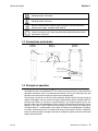
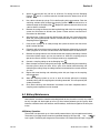
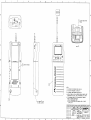
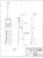
1.3 Connections and Labelin
Sideview
M odel 615
Endview
M odel 615
Rearview
M odel 615
D C input
Sam pling system input
S am pling system output
R S232 connection
and external pow er
input from B aseS tation
B attery com partm ent
1.4 Principle of operation
The Model 615 uses the CAPNOSTAT® CO2 sensor to measure CO2 by using the infrared
absorbtion technique, which has endured and evolved in the clinical setting for over two
decades and remains the most popular and versatile technique today.
The principle is based on the fact that CO2 molecules absorb infrared (IR) light energy of
specific wavelengths, with the amount of energy absorbed being directly related to the CO 2
concentration. When an IR beam is passed through a gas sample containing CO2 , the
electronic signal from the photodetector (which measures the remaining light energy) can be
obtained. This signal is then compared to the energy of the IR source and calibrated to
accurately reflect C 2 concentration in the sample. To calibrate, the photodetector’s response
to a known concentration of CO 2 is stored at the factory in the monitor’s memory. A reference
channel accounts for optical changes in the sensor, allowing the system to remain in calibration
without user intervention.
Rev. 00
Model 615 Service Manua
3
Section 2
Safety
Section 2
Safety
For maximum patient and operator safety, you must follow the following warnings and cautions.
WARNINGS
Indicates a potentially harmful condition that can lead to personal injury.
• Explosion Hazard: DO NOT use Model 615 in the presence of flammable anesthetics. Use
of this instrument in such an environment may present an explosion hazard.
• Electrical Shock Hazard: Always turn Model 615 off and remove any external devices
before cleaning it. Refer servicing to qualified service personnel.
• Failure of Operation: If the monitor fails to respond as described, do not use it until the
situation has been corrected by qualified personnel.
• Do not operate Model 615 if it appears to have been dropped or damaged.
• Do not operate Model 615 or its accessories when it is wet due to spills or condensation.
• Never sterilize or immerse the monitor, sensor or accessories in liquids.
• The monitor does not alert for NO RESPIRATION if the airway adapter is removed from the
CAPNOSTAT® CO2 sensor.
• Verify the “No Resp Timer” setting prior to use.
• Do not position any sensor cable in a way that may cause entanglement or strangulation.
• The Model 615 is not intended to be used as a primary diagnostic apnea monitor and/or
recording device.
• The external battery charger should NOT be used to recharge the battery near or in close
proximity to patients and/or other medical equipment in operation. It is intended for use in
service areas only (i.e. nurses station, biomed lab, etc.).
• Connection of an external device (e.g. printer or computer) to the RS232 serial port on the
BaseStation may compromise patient safety.
CAUTIONS
Indicates a condition that may lead to equipment damage or malfunction.
• Federal (U.S.A.) law restricts this device to sale, distribution, or use by or on the order of a
licensed medical practitioner.
• Use only an external power supply approved by Novametrix for use with this device. Use
of any other power supply may damage the Model 615 and void the warranty.
• Do not operate Model 615 or its accessories when it is wet due to spills or condensation.
• Do not operate Model 615 if it appears to have been dropped or damaged.
• Keep Model 615 and its accessories clean.
• Inspect the integrity of the Model 615 and its accessories prior to use.
• Never sterilize or immerse the monitor, sensor or accessories in liquids.
• Do not sterilize or immerse sensors except as directed in this manual.
• Do not apply excessive tension to any sensor cable or pneumatic tubing.
• Do not store the monitor or sensors at temperatures less than 14°F (-10°C) or above 131°F
(55°C).
• Do not operate the monitor or sensors at temperatures below 50°F (10°C) or above 104°F
(40°C).
4
Model 615 Service Manual
Rev. 00
Section 2
Safety
• If a Single Patient Use Sampling Adapter becomes occluded, replace and discard the
adapter.
• It is recommended that the CAPNOSTAT® CO2 sensor be removed from the circuit
whenever an aerosolized medication is delivered. This is due to the increased viscosity of
the medications which may contaminate the sensor windows, causing the sensor to fail
prematurely.
• Where electromagnetic devices (i.e. electrocautery) are used, patient monitoring may be
interrupted due to electromagnetic interference. Electromagnetic fields up to 3V/m will not
adversely affect system performance.
• Refer servicing to qualified personnel.
NOTES
Indicates points of particular interest or emphasis for more efficient or convenient operation.
• The Model 615 monitor is intended for operation with Novametrix Single Patient Use airway
adapters.
• Operating the Model 615 below 50°F (10°C) will result in longer warm-up time and reduce
battery life.
• Components of this product and its associated accessories which have patient contact are
free of latex.
• Certain rebreathing circuits, or the presence of artifacts such as cardiogenic oscillations,
may cause Model 615 to react to non-respiratory CO2 fluctuations as if they were breaths.
This condition affects only the RESP numerical displays; the capnogram display continues
to provide an accurate picture of the CO2 waveform.
• After the life cycle of our equipment and all accessories has been met, disposal of the
equipment should be accomplished following the national requirements. Contact the local
Novametrix representative for questions concerning disposal.
Rev. 00
Model 615 Service Manua
5
Section 2
Safety
[This page intentionally blank.]
6
Model 615 Service Manual
Rev. 00
Section 3
Theory of Operation
The Model 615 is a microprocessor based handheld instrument that measures the clinica
parameters of CO2 production and respiration rate (RR). The electronic theory of operation of
the Model 615 is explained in detail in the subsections that follow.
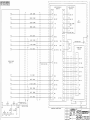
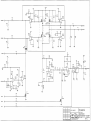
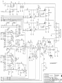
3.1 Digital Control System
Refer to 2754-03 schematic sheet 1.
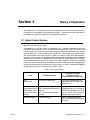
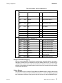
Embedded control for the system is provided by IC1, a Motorola MC68332 integrated
microcontroller. In addition to a full 32-bit Central Processing Unit (CPU), this device also
contains circuitry for system clock generation, peripheral chip select generation, data control,
interrupt generation, a sophisticated timing coprocessor, synchronous serial communication
and asynchronous serial communication. In general, functional signals are grouped together
into ports, and each signal can be independently programmed by software to be its predefined
port function or as discrete I/O. Additionally, the functionality for several ports (Port C, E and F)
can be predefined by the state of the data bus on system power-up. A special “background
mode” port allows the device to be controlled by an external source for system debugging and
testing. Also integrated on-chip are several activity monitors, as well as a software watchdog to
ensure proper device and system operation. Refer to table 1.
Table 1: CPU Port Functions
Rev. 00
Functionality Control ,
Data Bus Control
(Alt Functions: D pulled low)
Port
Defined Function
TPU
16 Channels
Timing Signal Generation
Each channel independently user
programmable as TPU function or
as Discrete I/O
QSM
4 Synchronous Serial
Chip Selects & one
asynchronous serial
channel
Serial Communications Port:
QSPI: Queued Serial Peripheral
Interface
SCI: Serial Communications
Interface
QSPI chip selects independently
user programmable, can be used as
Discrete I/O or decoded to create up
to 16 chip selects. SCI transmit can
be programmed as Discrete I/O
Background Mode
System debugging
Allows an appropriate external
device to control the microprocessor
and system
Model 615 Service Manua
7
Section 3
Theory of Operation
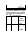
Table 1: CPU Port Functions
C
Chip Selects
D0: CSBOOT* data width, 8 or 16bit
D1: CS1*-CS3* or
BR*,BG*,BGACK*
D2: CS3*-CS5* or FC0-FC2
D3-D7: CS6*-CS10* or A19-A23
E
Bus Control
D8: Control Signals or discrete I/O
F
MODCK and Interrupts
D9: MODCK & IRQ or discrete I/O
The maximum operating frequency of the integrated processor is 20.97 MHz. The operating
frequency is software selectable and generated by an internal VCO operating from Y1, a
32.768KHz watch crystal. The Timing Processor Unit (TPU) coprocessor of the MC68332
provides timing generation derived from the system clock. This feature is utilized to control the
precise timing required for the acquisition of the end tidal carbon dioxide (EtCO 2) signals. The
TPU is also use to generate the PWM (Pulse Width Modulation) control for the CAPNOSTAT ®
CO2 sensor case and detector heaters, as well as to provide the frequency generation for the
audio tones. See Tables 2 & 3.
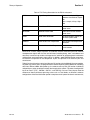
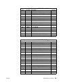
Table 2: TPU Timing Generation for the EtCO2 subsystem
Signal Name
8
Description
Function / Timing
CO2AZ
Auto Zero
Clears the sample/hold circuitry
prior to data acquisition.
Active high, 2.84 ms
CO2PWENB
Pulse Width Enable
Defines the active time for both
phases of the bipolar source
pulse, used for pulse width protection circuitry.
Active high, 830 µs
SRCDRV0
Source Drive 0
First source drive signal.
Active high, 405 µs
CS*/H
Current Sample/Hold
Enables circuitry for source current measurement. Sample is
taken when SRCDRV0 is
active.
Low = sample, 270 µs, High =
hold
SRCDRV1
Source Drive 1
Second source drive signal
delayed for 30 microseconds
after SRCDRV0 ends.
Active high, 395 µs
Model 615 Service Manual
Rev. 00
Section 3
Theory of Operation
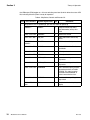
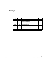
Table 2: TPU Timing Generation for the EtCO2 subsystem
SS*/H
Signal Sample/Hold
Enables circuitry for CO2 and
reference channel data acquisition.
Low = sample, 270 µs, High =
hold
CASEPWM
Case Heater PWM
PWM control for the case
heater servo
DETPWM
Detector Heater PWM
PWM control for the detector
heater servo
TONE
Audio Tone Generation
Variable frequency outputs to
generate system audio
CASEOT
Case Heater Over Temperature
Case heater over temperature
shut down
DETOT
Detector Heater Over Temperature Detector heater over temperature shut down
Ferrite and L-C filters, 100pF capacitors, and 100 ohm resistors have been placed on selected
microprocessor signals with fast rise and fall times (including timing, clock, and address and
data lines) in order to help reduce and suppress the radiation of electromagnetic interference
and decouple unwanted power supply noise. In addition, good EMI/EMC design techniques
have been incorporated in the component layout and printed circuit board layout and
manufacture.
Table 4 lists the chip select, control and discrete I/O functions for the Model 615 system module.
On power-up, Ports E and F are programmed as discrete inputs by pulling down their controlling
data lines, DB8 and DB9. After power-up, the software sets up each pin function individually
and performs a series of self tests to check the integrity of the system. The state of configuration
inputs on Port E (TST*, CNFG0*, CNFG1*, and CNFG2) are read. These inputs allow the
software to identify different operating states such as Test Mode, or different hardware
configurations. After the initialization period is complete and all system functions have been set,
Rev. 00
Model 615 Service Manua
9
Section 3
Theory of Operation
the LED output (PF0) toggles at a 1Hz rate switching transistor Q3 which drives the status LED
D3, indicating that the system is ready for operation.
Table 3: Chip Select, Control and Discrete I/O
Port
C
Pin Functions
I/O
Comments
D0 pulled low, D1-D7 pulled high, pins are chip select on power-up
CSBOOT*
10
System Signal Name
O
Program PROM chip select
byte wide mode, (8-bits) D0 =
LOW
CS0* / PC0 / BR* SRAMWR*
O
SRAM write enable
CS1*/ PC1 / BG*
AUD_CS*
O
Audio attenuation control chip
select
CS2* / PC2 /
BGACK*
SRAMRD*
O
SRAM read enable, byte mode
CS3* / PC3 / FC0 ROMWR*
O
FLASH PROM Write Enable,
Byte Mode
CS4* / PC4 / FC1 DISPCS1*
O
LCD chip select #1
CS5* / PC5 / FC2 DISPCS2*
O
LCD chip select #2
CS6* / PC6 / A19 LATCH1_CS*
O
System control signals latch 1
chip select
CS7* / PC7 / A20 LATCH2_CS*
O
System control signals latch 2
chip select
CS8* / PC8 / A21 ROMWREN
O
Port C discrete output, prevents
unintentional writes to FLASH
EPROM. This signal must be
asserted before ROMWR* in
order to overwrite the flash.
CS9* / PC9 / A22 PROFILE*
O
Enables software profiling data
output latch
CS10* / ECLK /
A23
O
Enable clock for the liquid crystal
display
Model 615 Service Manual
ROMOE*
ECLK
Rev. 00
Section 3
Theory of Operation
Table 3: Chip Select, Control and Discrete I/O
E
F
D8 pulled low, discrete I/O on power-up
DSACK0* / Port
E0
TST*
I
Initiate system TEST if low
DSACK1* / Port
E1
DS1*
I
Data and size acknowledge 1*
AVC*
E2
/ Port
CNFG0*
I
Configuration switch 0
RMC*
E3
/ Port
CNFG1*
I
Configuration switch 1
DS*
E4
/ Port
DS*
O
Data strobe
AS*
/ Port E5 AS*
O
Address strobe
SIZ0*
/ Port E6 CNFG2*
I
Configuration switch 2
SIZ1*
/ Port E7 SLP*
I
Not used in Model 615
R/W*
WR*
O
Data write strobe
MODCK / Port F0 LED
O
LED CPU activity Indicator
IRQ1*
/ Port F1 SW1
I
Keypanel switch 1 input
IRQ2*
/ Port F2 SW2
I
Keypanel switch 2 input
IRQ3*
/ Port F3 SW3
I
Keypanel switch 3 input
IRQ4*
/ Port F4 SW4
I
Keypanel switch 4 input
IRQ5*
/ Port F5 PWRKEY
I
Power key status input
IRQ6*
/ Port F6 EXTDCIN
I
Indicates external AC mains
power operation
IRQ7*
/ Port F7 NMI
I
Non-maskable interrupt
D9 pulled low, discrete I/O on power-up
Background Mode Debugging
External system debugging is possible by connecting an appropriate device (emulator or
debugger) to header J401 and momentarily bring the BERR* (J401/2) low. This halts the bus
activity and turns control of the system over to the external device. In this mode, internal MPU
registers can be viewed and altered, special test features can be invoked and system memory
can be read and written to.
System Memory
An 8-bit wide data path is used for FLASH PROM and SRAM transfers. Program code storage
is contained in a 1-Meg 5V FLASH or EEPROM (IC2) device. The FLASH PROM is protected
from unintentional overwrites of the program code by transistor Q1 and the ROMWREN signal.
Rev. 00
Model 615 Service Manua
11
Section 3
Theory of Operation
The ROMWREN line must be high prior to writing new code into the FLASH devices.
Nonvolatile data storage is contained in the 1-Meg SRAM (IC3). The SRAM is backed-up to
retain it’s contents by applying a voltage on VBACKUP generated by BT1 (a 3.0V lithium
battery) when power is off or the battery is removed from the monitor. During the battery backup
state, transistor Q2 keeps the CS1* control of the SRAM in the inactive state. This forces the
data bus to a high impedance state, isolating the SRAM from the rest of the system. True
nonvolatile storage for the bootstrap parameters for the CAPNOSTAT® CO2 sensor are stored
in a serial EEPROM (IC2) located on the Interface (2753) board.
Serial Communications
Refer to 2754-03 schematic sheet 6.
The on-chip (IC1) asynchronous serial communications interface (SCI) channel is contained in
the MC68332. The signals are level shifted to standard RS232 levels by IC26 which is a Dual
RS232 Communications Driver/Receiver. The transmitters in the RS232 level shifter are under
software control to minimize the patient leakage current to the rear panel connector (J101
when communication is not active. The signal COMMPWR controls the transmitters operation
and is derived from IC9 pin 14 (schematic sheet 2). The serial connection to external, nonpatient contact devices is electrically isolated from the patient through the CAPNOSTAT® CO2
sensor airway adapter. This connector, J101 is located on the rear panel and is designed to
interface with external devices (i.e. computer, printer) when placed in a base station which
contains the mating connector. In addition there is a 4 pin connector (J403) available for test
and service which offers an internal connection to the serial communications at a TTL level. The
data signals ASRxD and ASTxD are logic level signals and are diode protected against over
voltage by D22 and D23 should IC26 breakdown from ESD (schematic page 6). Refer to Table
5 for the pinout and signals of serial interface connector J101.
Table 4: Power/Communications 6-pin modular connector J101 located on the rear panel.
Pin Number
Signal
Function
1
RxD
Internal MC68332 UART Receive, RS232 Signal, Level
Shifted
2
TxD
Internal MC68332 UART Transmit, RS232 Signal, Level
Shifted
3
DGND
Digital Ground
4
DGND
Digital Ground
+VCHG
External DC input supply to power unit and battery charger
5
6
User Interface Control Circuitry
Refer to 2754-03 schematic sheet 2.
The user interface features a 64 row by 128 column Liquid Crystal Display (LCD) module with
an LED backlight. A 5-switch membrane keypanel is provided for operator entry. The use
interface also contains three LED’s which represent various system conditions.
Control of the user interface is provided by the LATCH1_CS* chip select signal together with
the Port F input signals from the microprocessor. SW1-SW4 are inputs which read in the
12
Model 615 Service Manual
Rev. 00
Section 3
Theory of Operation
present state of the membrane keys. Depressing a key causes the signal line to be pulled low
in contrast to its normally high state. IC9 provides a latched output for controlling the status
LED’s. The LCD backlight is a series of LED’s which are driven by a 5.12kHz clock signal in
order to lower the LCD backlight power requirement and is activated by the backlight
membrane key. The LITE_CLK signal is a 5.12kHz logic level signal generated by IC7 (sheet
7) which modulates the LED backlight through FET switch Q4 (BKLGHT_OUT) when asserted
by IC10 (BACKLIGHT). This signal is capacitively coupled by C42 in order to prevent the
backlight from remaining on in the event of a system failure.
Contrast control for the LCD is provided by DAC IC33 (sheet 6) and amplifier IC34A and
transistor Q18 (schematic sheet 6). When the CPU detects a press and hold of the backlight
membrane key, the CPU sends a digital ramp input to the DAC which causes the output to
change accordingly. Inverting amplifier IC34A controls the base current into transistor Q18,
which changes the level of the display contrast voltage, VDISP.
Refer to schematic sheet 6.
An audio frequency tone is generated by the TPU (Time Processor Unit) of the MC68332
(TONE). This signal is fed into the divider network consisting of R183 and IC32. IC32 is a 10k
ohm E2 potentiometer whose value (when written to under software control) provides a means
for attenuating the signal under CPU control. From the divider output the signal is amplified by
IC34B and Q17 which drives the system speaker (LS1) to produce system audio. The AUD_EN
line from IC9 controls Q19, when high the input to IC34B is grounded thus muting the audio.
Real Time Clock, Power on RESET Generation and Glue Logic
Refer to 2754-03 schematic sheets 1 and 2.
Time-keeping for date and time stamping of patient trend information is provided by IC8. This
device contains a built-in crystal for precise time and date measurement. In the absence of
digital power, the time keeping function is maintained by the battery backed supply, VBACKUP
which is generated by the 3V lithium backup battery (BT1).
On power-up, the system is forced into a “Reset” state by IC4 (sheet 1). When the suppl
voltage VDD, approaches 1V, the SRST* line is asserted to prevent undefined operation. IC4
also provides supervision over the VDD logic supply. If the logic supply falls below 4.55V
±120mV then IC4 generates a reset condition until the supply returns to a safe level. Inverter
IC5 is used to generate the active high RESET signal.
The Model 615 makes use of the high level of integration offered by the MC68332. Therefore
the glue logic required is a minimum. Chip selection for the serial peripherals is provided by
decoding the queued serial module (QSM) (PCS0-PCS3) of the microprocessor IC1 (sheet 1
on schematic) using decoder IC12 (sheet 2) while parallel interface peripherals are selected by
the internal chip select registers of Port C (BOOTCS* and CS0*:CS10*). Latch IC10 is used to
control the saturation analog signal processing, the LCD backlight, the sidestream sampling
pump, and to power the monitor off.
3.2 CO2 System Analog Subsections
CO2 Source Drive
Refer to 2754-03 schematic page 3 and Table 2 of this document.
The source drive circuitry is designed to drive the source with a bipolar signal to prevent the
migration of charges within the source that may result from unidirectional electrical fields. The
Rev. 00
Model 615 Service Manua
13
Section 3
Theory of Operation
resistance of the source is monitored constantly to ensure the integrity of the system by
sampling the current through the source while it is active.
The SRCDRV0 and SRCDRV1 lines are used to control the bipolar signal that drives the
source. The SRCDRV0 signal goes high as soon as the CO2AZ (Auto Zero) line goes low and
the CO2PWENB (Pulse Width Enable) line goes high. The duration of SRCDRV0 is 405 us
(microseconds), and drives the source in the positive direction. The SRCDRV1 line drives the
source with an opposite polarity signal when high for the same duration. There is a 30 us delay
from the time the SRCDRV0 line goes low to when the SCRDRV1 line goes high. This delay is
to prevent the possibility of both SRCDRV0 and SRCDRV1 being active at the same time, thus
creating a low impedance path between the two supplies (power supply shoot-through).
SRCDRV1 steers current through the source in an opposite direction from SRCDRV0.
When SRCDRV0 and CO2INH (Inhibit) are high, the output of MOSFET Driver IC13A pin 7 will
go low. This turns the P-Channel half of MOSFET Q5 on. At the same time, the output of
MOSFET Driver IC14B pin 6 will be high biasing on the N-Channel half of MOSFET Q6 on. With
both Q5B P-Channel and Q6A N-Channel on, current will flow from +VSRC through Q5B to the
positive source terminal, then back from the source negative terminal through Q6A, through
R97 to -VSRC. When SRCDRV0 returns low, both Q5B and Q6A are turned off and no current
flows through the source. After the 30 us delay, SRCDRV1 will go high. The output of IC14A pin
8 will go high, biasing the N-Channel section of MOSFET Q5 on. The output of IC13B pin 5 will
go low, turning the P-Channel of Q6 on. Current will now flow from +VSRC through Q6B to the
source negative terminal, back from the source positive terminal through Q5A and R97 to VSRC. Current will cease to flow when SRCDRV1 goes low. The bridge circuit of Q5 and Q6 in
effect switches the polarity of the drive signal of the source between +VSRC and -VSRC.
CO2PWENB also falls with the falling edge of SCRDRV1, signaling the end of source activity.
When current flows through the source, it will also flow through current sensing resistor R97,
creating a differential voltage proportional to the source current:
VSRC = (VSR / RSR) * RS * AV(DA) where:
VSRC =voltage out of difference amplifier proportional to current
through the source element = 24V +/- 0.625V
VSR =differential voltage across the source element
RSR =resistance of the source element
RS=resistance of the current sensing resistor = 1 ohm
AV(DA)=difference amplifier gain = 5
VSRC =[120 (Volts*Ohms) /
SR]
The voltage signal out of difference amplifier IC15B is level shifted through C52 and fed to the
sample and hold IC16A via buffer amplifier IC15A. A low level on the CS*/H (Current Sample
and Hold) signal allows the source current signal to be sampled. On the rising edge of CS*/H,
the present voltage level of the source current signal is held and appears at the input to channel
A2 of the Analog to Digital Converter IC6 (sheet 2 on schematic) for processing by the MPU.
When CO2AZ is high, the input to the sample and hold of IC16A is grounded to discharge any
residual charge that may be on C52.
In order to prevent the source from being driven until the system is up and ready, there i
protection circuitry that inhibits the source drive until enabled. During system power-up, the
RESET line keeps Q7 on. This causes the CO2INH line to be brought low, preventing source
pulses by pulling down SRCDRV0 and SCRDRV1 through D6. Protection circuitry also guards
against extended pulse width as well as shortened duty cycle. On the rising edge of
CO2PWENB, the trip point of IC17B is exceeded, allowing C55 to charge through R100. If the
14
Model 615 Service Manual
Rev. 00
Section 3
Theory of Operation
SRCDRV signals do not turn the Source Pulse off within 200 us after the 830 us pulse period,
the trip point for IC17A will be exceeded, pulling the CO2INH line low turning the Pulse off.
After the CO2PWENB signal returns low, capacitor C57 discharges through R101, keeping the
output of comparator IC17B at the voltage acquired by C55. After approximately 10.4 ms, C57
will have discharged below the comparator trip point. The comparator output goes low,
discharging C55 and the circuit is ready for the next source pulse cycle.
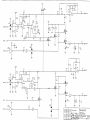
CAPNOSTAT® CO2 sensor Case and Detector Heater Control
Refer to 2754-03 schematic sheet 4.
The temperature of the system directly affects its ability to accurately measure CO2 and
therefore must be precisely maintained at a controlled value. Two separate heaters and control
circuitry are used; one regulates the temperature of the detectors for the CO 2 data and
reference channels; the other regulates the temperature of the transducer case (and loosely
maintains the temperature of the airway adapter). While the purpose of the detector heater is
to keep the detectors' sensitivity to infrared radiation constant, the function of the case heater
is to keep condensation from forming on the airway windows by elevating the window
temperature above the ambient airway temperature. Both heaters use an efficient pulse-width
modulation scheme designed to decrease power consumption, with the PWM timing generated
by the TPU under microprocessor control. This control loop is run by the CPU which does the
calculations and passes the duty cycle to the TPU. For the purpose of describing the regulation
loop, the case heater circuitry will be considered. The detector and case heater circuitry are
identical.
Inside the CAPNOSTAT® CO2 sensor, a sensing thermistor is thermally connected to the heater
module. Initially, the CAPNOSTAT ® CO2 sensor is at the ambient temperature and the
resistance of the thermistor is large. A small current flows through the signal path
“CASETHERM” and only a small voltage is developed across R117. The microprocessor
programs the TPU to allow a maximum duty cycle of 90% to power the PWM heater circuitry.
This causes the heater control MOSFET Q9B to be pulsed on and off with a duty cycle that is
under direct control of the program software. As the heater warms up the case, the thermistor's
resistance decreases, raising the voltage appearing at the input of the control loop. As
described below, the MPU looks at this voltage and decreases the duty cycle of the PWM
control circuitry, gradually reducing the power output into the heater. When the desired
temperature set point is reached, a balance is struck between the energy delivered to the
system and the heat flow out of the system.
The case thermistor is sensed by amplifier IC18A pin 3. The difference between the signal at
the non-inverting input and the reference appearing at the inverting terminal generates an error
voltage proportional to the sensed temperature at the amplifier's output:
eo (V) = [83.133V / (Rth+3.32K)] - 10.2V where:
eo = amplifier output voltage
Rth = resistance of the thermistor = 4.36933K at 45°C
Temp (°C) = 4.1288 (°C/V) * eo (T) V + 41.7321°C
where eo = amplifier output voltage at temperature T
This error voltage is low pass filtered by amplifier IC20A, sent to the ADC (IC6) and processed
by the CPU to regulate the output pulses from the TPU. The TPU PWM signal is buffered by
MOSFET Driver IC19A and capacitively coupled to the gate of the heater drive MOSFET, Q9B.
Capacitive coupling the signal prevents a system fault that would allow the PWM to be stuck at
a level that would cause too high of a heater output. In the absence of a pulse, the gate drive
Rev. 00
Model 615 Service Manua
15
Section 3
Theory of Operation
will be pulled high, disabling the output to the heater. The pulsed voltage signal out of the
MOSFET is filtered by D12, L6, C68 and C69 to produce a DC output level for the heater. Since
the TPU generated PWM signal is based on the system clock, it is synchronized with the
generation of the source pulse timing. This minimizes the effect of any random disturbance
caused by the heater circuit on the detection of the CO2 data and reference signals.
The error voltage out of amplifier IC18A also appears at the temperature watchdog comparator
IC17C. If the error voltage reaches a voltage equivalent to 56 degrees Celsius, the comparator
trips, turning Q10 off. The gate of MOSFET Q9A is pulled high by R116, which turns it off and
VHTR is prevented from reaching the source of transistor Q9B. The temperature of the sensor
is also monitored by the MPU which will disable the heater when a temperature of 50 degrees
Celsius is exceeded. To shut off the heater, the MPU asserts the CASEOT signal, turning Q11
on which turns Q10 and Q9A off.
CO2 Input Signal Path
Refer to 2754-03 schematic sheet 5.
The signals from the sensor “CO2DATAIN” (CO2 Data) and “CO2REFIN” (reference signal)
have similar signal paths. The CO2DATAIN passes through a high pass filter with a gain of 3.8
consisting of C80, R148 and buffer amplifier IC21B. The signal is fed to a Butterworth low pass
filter IC21A and associated components. This filter has a gain of 2 with a corner frequency of
1.5 KHz. The output from the low pass filter is fed to a 12-bit digital to analog converter IC22.
The signal, “CO2DIN” comes into the reference of the DAC, which acts as a programmable gain
stage followed internally by an amplifier with a fixed gain of 2. Here under processor control the
signal's gain is adjusted to an acceptable level for conversion. The gain setting is adjusted using
the digitized signal out of the A/D Converter (IC6) as part of the feedback loop. Similarly,
“CO2REFIN” is conditioned by high pass filter IC21D with a gain of 1.75 and low pass filter
IC21C with a gain of 2. The equivalent fixed gains for the two input signals are not equal in order
to compensate for differences in the output signal levels of the infra-red detectors in the sensor.
The output from IC22 is buffered by IC24A and AC coupled through C91 to IC23A. The
“CO2DATAIN” signal received from the sensor is ac coupled prior to the initial gain stage and
high pass filtered to remove any DC bias by C80. Prior to sampling CO2 signal, the “CO2AZ”
(Auto Zero) pulse biases Q15 on, causing any residual charge on C91 to discharge to ground.
At the start of the source pulse, the “CO2AZ” pulse goes low and the CO2 signal from the sensor
is attained, and appears at the input of the sample and hold amplifier, IC16B. Near the end of
the source pulse, the “SS*/H” (Signal Sample and Hold) goes low and the peak signal is
acquired on the internal sample and hold capacitor. “SS*/H” returns high at the end of the cycle,
and the CO2 signal on the sample capacitor is held at the peak value. The signal then passes
through a low pass filter of R159 and C92 before being converted by the ADC into digital data
and analyzed by the processor. The signal “CO2REFIN” follows an identical zeroing and
acquisition path.
CAPNOSTAT® CO2 sensor Interface
Refer to schematics 2754-03 sheet 5 and 2753-03 sheet 1.
Twenty pins of 60 pin connector J404 interface the CAPNOSTAT® CO2 sensor with the system
electronics. Ferrite and L-C filters have been placed on selected lines to suppress radiated EMI
and reduce susceptibility from external sources of interference.
Barometric Pressure Circuitry
Refer to 2754-03 schematic sheet 6.
16
Model 615 Service Manual
Rev. 00
Section 3
Theory of Operation
IC28 is a piezoresistive differential pressure transducer with port P2 held as close to 0 psi (a
perfect vacuum) as is possible. It measures the absolute pressure difference at port P1 relative
to the vacuum at port P2. The transducer is calibrated for a full scale output of 0 to 15 psi, has
internal temperature compensation and is designed to be driven by a constant voltage source.
Instrumentation amplifier IC30 conditions this signal to correspond to the current barometric
pressure, which is set by adjusting VR1. The nominal gain of this amplifier is 93.56, which
corresponds to an ADC count of 3800 at 760 mmHg. The output signal from IC30 is low pass
filtered by IC29A and appears as an input (ABPRESS) to the 12-bit ADC.
Sampling Pump
Refer to 2754-03 schematic sheet 2.
To enable the monitoring of non-intubated patients, a single tapered sampling port is provided
on the sensor interface panel. Voltage regulator IC49 adjusts the pump motor speed to set the
flow rate of air through the tubing system for 180ml/min. Resistor’s R275 and R277 set the
voltage to approximately 2.5V. VR2 is a potentiometer in parallel with R277, which can be
installed if more accuracy is required for a flow rate adjustment. Pump motor current is sensed
by measuring the voltage developed across resistor R278 using amplifier IC50 that provides a
gain of 63. This provides an output of 8mA per 1/2 Volt { o = (Ipump*R) / Gain} into the 12-bit
ADC, or approximately 2.5 uA per bit resolution {Vref(ADC) / (212*Gain)}* {4mA/V}. A two-pole
31 Hz filter composed of IC29B provides high frequency attenuation. The VPUMP signal is
digitally converted by IC6 and monitored by the processor.
Digital and Analog Control Lines
Refer to 2754-03 schematic sheet 2.
IC10 is enabled by the LATCH2_CS* line from the processor, the D8-D15 data lines then control
the following signals:
SPO2CAL
Not used
SPO2SC1
Not used
SPO2LPON
Not used
INSIG
Not used
SIGND
Not used
BACKLIGHT
Used with LITE_CLK for display’s backlight control
POWER_ON
Powers the monitor down (active low)
PUMP_CTRL
Controls sampling pump
Analog signals in the system are converted to digital values by IC6 then analyzed by the
processor
Rev. 00
CO2DATA
CO2 data channel
CO2REF
CO2 reference channel
CO2ISRC
Current through CO2 sensor’s source
CO2CASE
CO2 sensor case temperature
CO2DET
CO2 sensor detector temperature
ABPRESS
Barometric pressure
SPO2FEDC
Not used
Model 615 Service Manua
17
Section 3
Theory of Operation
SPO2IRLED
Not used
SPO2IRLED
Not used
VPUMP
Monitors current through the sampling pump
VBATTADC
Battery voltage level
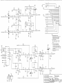
3.3 Power Supply and Battery Charger
Supply and Reference Voltage Generation
Refer to 2754-03 schematic sheet 8.
The monitor operates from either an isolated external DC power supply or from the internal
battery. There are two options presently for the internal battery, a Nickel Metal Hydride battery
pack (NiMH), or a Disposable AA Lithium cell pack. The NiMH battery pack operates from a
nominal voltage of 7.2V down to 6.0V while the AA Lithium pack operates from 10.5V down to
6.0V. This battery voltage range is monitored in hardware by the 12-bit ADC for level and
comparator IC37A in order to shut the unit down at approx. 6.0V. The NiMH battery can be
charged either externally via a separate charger or internally when the DC input is connected
and a NiMH battery is installed. The internal battery charging circuitry is located on the 275301 assembly and is described in a later section of this document. The Lithium battery pack has
a schottkey diode in series with the positive battery terminal to prevent accidental charging of
the Lithium cells.
The core of the power supply design for the system is a 500 KHz switching regulator, IC36, that
utilizes a flyback transformer configuration to generate the analog DC supply voltages. The
primary of the transformer is designed to accept 6.0 to 13 V DC input and provides secondary
outputs of nominally +13.75VDC, and -13.75VDC which are regulated by R204 and R210 off of
the +VA supply. These supplies (±VA) feed all of the analog circuitry in the monitor. All supplies
are L-C filtered to minimize noise in the analog front end. An additional switching regulato
(IC41) generates the 5VDC supply (VDD) which feeds all the logic circuitry in addition to a
filtered version (CVDD) which supplies the logic level requirements of the CO2 signal path (i.e.
data converters e.t.c.). The 5V supply is L-C filtered to provide clean logic supplies for the
analog sections of the CO2 (CVDD) system. IC35 and IC40 are linear regulators which provide
clean, well regulated supplies (±CVA) for the CAPNOSTAT® CO2 sensor. IC38 and IC39 are
designed as a tracking regulator pair to provide a 24VDC differential voltage for powering the
CAPNOSTAT® CO2 sensor source (+VSRC, -VSRC). Power for the CAPNOSTAT® CO2 sensor
heaters is supplied by VDCIN for maximum efficiency.
18
Model 615 Service Manual
Rev. 00
Section 3
Theory of Operation
Refer to Table 6 for power supply breakdown.
Table 5: Power Supply and Reference Outputs
Signal
Rev. 00
Supply
Description
VDCIN
+6.0 V to +13 VDC
Main DC input generated from external DC input or internal battery.
VBATT
+6.0 V to +10.2
VDC
Internal battery DC input, max level dependent on battery
installed.
VBACKUP
+2.5 VDC or +5
VDC
Supply for SRAM and real time clock, either VDD or 2.5V
to maintain SRAM data during power down.
VHTR
VDCIN
Supply for the CAPNOSTAT® CO2 sensor case and
detector heaters, supplied by battery or external DC input.
When powered by battery heater power follows input
power.
VDD
+5 VDC
Regulated digital logic supply .
CVDD
+5 VDC
Regulated and filtered logic supply for CO2 analog front
end.
+VA
+13.75 VDC (nomi- Tightly regulated +13.75V DC supply.
nal)
+CVA
+12 VDC
Linearly regulated and filtered positive supply for the
CAPNOSTAT® CO2 sensor and CO2 front ends.
+VSRC
+12 VDC
Linearly regulated and filtered positive supply for the
CAPNOSTAT® CO2 sensor source. Tracks -VSRC to provide a 24V +/- 2.5% differential voltage across the source.
-VSRC
-12 VDC
Linearly regulated and filtered negative supply for the
CAPNOSTAT® CO2 sensor source. Tracked by +VSRC to
provide a 24V +/- 2.5% differential voltage across the
source.
-VA
-13.75 VDC (nominal)
Loosely regulated off of the +13.75VDC feedback line.
- CVA
-12 VDC
Linearly regulated and filtered negative supply for the
CAPNOSTAT® CO2 sensor and CO2 front ends.
CVREF
+2.5 VDC
Buffered reference for the A/D converter.
2CVREF
+5.0 VDC
Buffered reference used in the CAPNOSTAT® CO2 sensor heater control circuitry.
-2CVREF
-5.0 VDC
Buffered reference used for the contrast control circuitry.
VREFO/2
+1.25 VDC
Buffered reference used for DC excitation for the barometric pressure sensor
Model 615 Service Manua
19
Section 3
Theory of Operation
Table 5: Power Supply and Reference Outputs
SPO2VLED
VDISP
0 to 2.5 VDC
-6.5 to -11.5 VDC
Not used
Negative bias supply for the LCD used to adjust the contrast level.
Refer to 2754-03 schematic sheet 6.
Stable reference voltages for the sensors and analog circuitry are derived from IC25, a
precision 2.5V reference generator with low drift. Five (2CVREF) and 2.5 Volt (CVREF)
references for the CO2 circuits are generated by IC27, while a separate –5.0 Volt (-2CVREF)
supply is generated directly from IC31A for –VA and -VD on the 20 bit ADC’s for the saturation
front end.
Refer to 2753-03 schematic
When the monitor is operated from the DC input power source the green AC ON indicator on
the front panel is lit. If DC input power is lost or is not available, the monitor automaticall
operates from its internal battery without interruption. The AC ON indicator is extinguished and
a BATTERY LED on the front panel lights up, indicating the current voltage level of the battery.
While on internal DC power, the current state of the battery is monitored by both software and
hardware (IC37 2754-03 schematic sheet 8). Should the battery power level get critically low,
the monitor software alerts the user. If the monitor is not placed on external DC input power
within approximately five minutes, the software will shut the unit off. Should the software fail to
turn the monitor off when the low battery alarm sounds, the hardware cutoff (IC37A) activates
(+VBATT=6.0V), turning the unit off. The trend memory data stored in SRAM is retained by the
presence of VBACKUP power which is generated by a 3 Volt on-board Lithium battery.
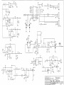
Battery Charger Circuitry
Refer to 2753-03 schematic sheet 1.
The internal NiMH battery (7.2V, 3Ahr) will charge when the monitor is connected to the external
DC power supply (9220-10) or installed in the Base Station option (PN. 6998-00) with the
external adapter connected to the Base Station.
Battery charging is controlled by IC1, a frequency modulated fast charge controller. IC1
monitors temperature, voltage, and time throughout the charging process to safely and
effectively charge the internal battery. The charger is configured to terminate charging using the
(delta temperature/delta time) method of charge termination. Charging is maintained at the C/
4 (750mA) rate while current to the battery is controlled by Q1, Q2, Q3, and the “MOD” output
of IC1. Q3 provides base drive for Q1 while Q2 serves to shut Q1 off very quickly on a cycle by
cycle basis, allowing the large currents required for charging to pass through Q1 which is a
surface mount SOT-23 package PNP transistor capable of 500mW’s of power dissipation.
Charge current is monitored at the SNS input (IC1/9) and is set by R13 (IREG = 0.2225V/
2*RSNS). Temperature is monitored using the battery’s internal thermistor, in conjunction with
R9, R10, and R12. R9, R10, and R12 set the deltaT/dt charge termination parameter to 1°C per
minute. R7 and R8 set the maximum temperature for charge termination (a safety override) to
45°C.
Battery charging is initiated in one of two ways: either by applying 13.0 VDC to +VCHG,
therefore providing VCC (BVDD) to IC1; or by inserting a rechargeable battery into the battery
compartment. Resistors R2 and R4 form a divider which sets the battery voltage window. If a
battery with a voltage below the lower threshold (V EDV, end discharge voltage, V EDV =
0.4*BVDD +/- 30mV or, 2.04V, +VBATT = 5.26V) is installed, the charger will remain in
maintenance mode until the threshold is reached. Conversely, if the battery exceeds the upper
20
Model 615 Service Manual
Rev. 00
Theory of Operation
Section 3
threshold for maximum cell voltage (VMCV, maximum cell voltage, VMCV = 0.8*BVDD +/- 30mV
or, 4.08V, +VBATT = 10.5V), charging will terminate. After fast charge is terminated, either by
deltaT/dt or by time-out, the charger switches over to a maintenance charge of C/64 to keep the
battery topped off. BVDD (VCC for IC1 and D4, the AC on indicator) is regulated by D10, a 5.1V
zener diode, while R3 keeps D10 operating in the knee region and C5 and C6 provide filtering.
Over-current protection is provided by F1, a 1A slo-blo replaceable fuse. Reverse leakage
protection is provided by D5 and D6 which prevent the battery from trying to power BVDD and
+VCHG in the battery operation state.
Rev. 00
Model 615 Service Manua
21
Section 3
Theory of Operation
[This page intentionally blank.]
22
Model 615 Service Manual
Rev. 00
Section 4
Functional Tests
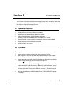
The Functional Test verifies overall functional integrity of the monitor and sensor. If the Model
615 monitor does not pass these tests, remove from use and contact the Novametrix Service
Department for repair/replacement assistance.
4.1 Equipment Required
1.
Single Patient Use Adult Airway Adapter PN: 6063-01
2.
Single Patient Use Neonatal Airway Adapter PN: 6312-01
3.
NiMH rechargeable battery pack PN:400043 or equivalent,
(batteries (7) “AA” 1.5V PN: 400050 and case PN: 6862-01, if supplied)
4.
External DC power supply PN: 9220-10 and hospital grade line cord PN: 600026
5.
Single Patient Use Sampling Adapter PN: 8954-01
6.
Sample line tubing and cannula
4.2 Procedure
Power up
Rev. 00
1.
Visually inspect the monitor and verify that there is no external damage.
2.
Open hinged cover and install the NiMH rechargeable battery pack (fully charged)
PN: 400043 into the unit.
3.
Connect the external DC power supply PN: 9220-10 to an AC outlet using a hospital
grade line cord, then plug the other end into the unit under test.
4.
Verify the LED on the keypanel illuminates.
5.
Power the unit up by pressing the POWER
key on the keypanel. The monitor will
display “Novametrix Medical Systems Inc. Model 615 Checking System” then the
adapter mode that was last selected and the current setting for the alert limits
(enabled or disabled). The keypanel LEDs will illuminate in sequence during the
power up sequence.
6.
Verify the monitor displays “CAPNO WARMING” then “CHECK ADAPTER” at the top
of the display.
Model 615 Service Manua
23
Section 4
Functional Tests
7.
Press both
and
keys simultaneously to display the configuration settings.
Before changing any parameter record the current settings so that the unit may be
returned to its’ original configuration. Use the PAGE
and SELECT
the following parameters (these are also the factory default settings):
GAS COMPENSATION
ROOM AIR
CO2 WAVEFORM SCALE
MEDIUM
CO2 WAVEFORM SPEED
MEDIUM
NO RESP TIMER
20 sec.
CO2 UNITS
mmHg
ALERT VOLUME
HIGH
RS232 INTERFACE
NOVACOMM
WAVEFORM FILL
UNFILLED
ETCO2 AVERAGING
10 SEC
ALERT LIMITS
DISABLED
RESP TREND SCALE
MEDIUM
AUTO POWER OFF
ENABLED
When all the parameters are set press the ADAPTER
keys to set
key to exit.
Capnography Tests
8.
Press the ADAPTER key and use the SELECT
press EXIT
key to select ADULT, then
9.
Connect a Single Pateint Use Adult Airway Adapter PN: 6063-01 to the
CAPNOSTAT® CO2 sensor. (Perform adapter zero only if requested by the monitor).
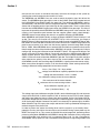
10.
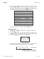
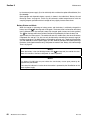
Press the PAGE key to display the CO
11.
Breathe into the airway adapter at a normal breath rate for at least 30 seconds, verify
both the readings and the waveform displayed on the unit are acceptable.
2
Waveform Screen.
Sample Waveform*
*(Waveform appearance will vary depending
upon breath rate and CO2 waveform speed.)
24
Model 615 Service Manual
Rev. 00
Section 4
Functional Tests
12.
Stop breathing into the adapter and verify an alert condition after approximately 20
seconds (alert LED flashing red and an audio alert). Press the ALERT key and
verify the alert tone silences. Verify a 2 minute audio silence is initiated and the LED
on this key is flashing red then yellow.
13.
Press the PAGE key until the ETCO 2 Trend Screen is displayed, verify a trend
waveform is present (waveform starts from right).
14.
Press the ALERT key.
15.
Change the airway adapter on the CAPNOSTAT® CO2 sensor from the adult to the
neonatal.
16.
Verify that “CHECK ADAPTER” is displayed.
17.
Press the ADAPTER
key and use the SELECT
key to select NEONATAL,
press EXIT
. Verify the unit is in the Neonatal Mode as indicated by the “NEO” on
the screen. (Perform adapter zero only if requested by the monitor).
Sidestream Tests
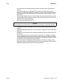
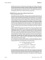
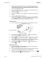
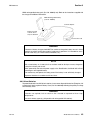
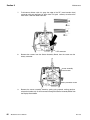
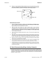
18.
Connect a Single Patient Use Sampling Adapter to the CAPNOSTAT CO2 sensor.
CAPNOSTAT CO2 sensor
connect cannula to here
sampling adapter
19.
Press the ADAPTER key then use the SELECT
key to select SAMPLING,
press EXIT
. Verify the sampling pump turns on.
20.
With all sources of CO 2 removed from the adapter and tubing, press and hold the
ADAPTER key for 4 seconds, then use the ZERO
key to zero the adapter.
21.
When the zero is complete, remove the Single Patient Use Sampling Adapter and
verify the pump turns off. Attach a Single Patient Use Adult Adapter.
22.
Press the ADAPTER key and use the SELECT
press EXIT
key to select ADULT, then
Miscellaneous Tests
Rev. 00
23.
Press the Backlight key and verify that the back light turns off. Press the backlight
key again and verify the back light turns on.
24.
Press and hold the Backlight
key and verify that the display contrast is adjustable
from light to dark. Set the contrast of the display to a viewable level.
25.
Remove the external DC power supply from the unit and verify that the
LED is off and the Battery
LED is illuminated (green).
AC
ON
Model 615 Service Manua
25
Section 4
26
Functional Tests
26.
Power the unit down then power it back up again. Ensure the monitor functions
properly on battery operation.
27.
Power the unit down and remove the rechargeable battery pack from the unit.
NOTE: The following steps do not apply if the monitor does not have an “AA” battery
pack.
28.
Install (7) seven “AA” batteries into the battery case PN:6862-01 ensuring proper polarity.
29.
Install the battery case into the unit, power up the unit and ensure it functions properly
on battery power.
30.
Turn the unit off by pressing the Power
key. Remove the battery pack from the
unit. Remove the “AA” batteries from the battery case.
Model 615 Service Manual
Rev. 00
Section 5
Accuracy Tests
Section 5
Accuracy Tests
The Accuracy Test verifies the performance accuracy of the Model 615. This test is typically
performed in conjunction with (after) the Functional Tests described on page 23. If the monitor
does not pass the accuracy test, remove from use and contact the Novametrix Service
Department for repair/replacement assistance.
This procedure assumes the technician performs each step as indicated—leaving the monitor
in a known state prior to performing the next step. If steps are omitted or performed out of order,
be sure that the monitor is set to the correct state before continuing.
5.1 Equipment Required
1.
Single Patient Use Adult Airway Adapter, PN: 6063-01, Qty 3
2.
NiMH rechargeable battery pack (fully charged), PN: 400043 or equivalent.
3.
External power supply, PN: 9220-10 and hospital grade line cord PN: 600026
4.
Model 1298 Gas Regulator, PN: 6081-00
5.
Precision gas mixture, PN: 8364-10
6.
Nova Princo Barometer or equivalent
7.
Thermometer (measure ambient room temperature)
5.2 Procedure
Rev. 00
1.
Visually inspect the monitor and verify that there are no cosmetic defects.
2.
Install a fully charged MiMH rechargeable battery pack (PN: 400043) into the unit
under test.
3.
Plug the external power supply (PN: 9220-10) into an AC outlet, then plug the other
end into the unit’s DC input.
4.
Hold the and keys down, press the POWER
and reset to factory defaults.
5.
The monitor will display "Resseting Monitor to Factory Defaults", then “Novametrix
Medical Systems Inc. Model 615 Checking System” then the adapter mode and the
current setting for the alert limits (enabled or disabled). The keypanel LEDs will
illuminate in sequence during the power up sequence.
key to turn the monitor on
Model 615 Service Manua
27
Section 5
Accuracy Tests
6.
Calculate the nominal CO2 readings using the following equation:
(CO2%) · (Pbaro)
N=
1-0.003 · (33-T)
Where:
Pbaro=barometric pressure in mmHg
T=temperature in degrees centigrade
N=the nominal corrected CO2 value for the given CO2%
CO2%=percentage of CO2 test gas used, e.g. 5% CO2 test gas = .05
Example:
If T=23 and Pbaro=760
then
N=((CO2%) · 760) / 1-0.003 · 10)
N=CO2% · 783.505
N=39.2 (for CO2%=.05 or 5% test gas)
For N<40; Low=N-2, High=N+2
For 40<N<70; Low=0.95 · N, High=1.05 · N
For N>70; Low=0.92 · N, High=1.08 · N
CO2%=5 N=39.2 Low=37.2 High=41.2
7.
Connect a Single Patient Use Adult Airway Adapter (PN: 6063-01) to the
CAPNOSTAT® CO2 sensor.
8.
Press and hold the
key until ">0< ?" appears on the screen. Ensure that the
sensor and adapter are clear of any source of CO2, including your breath. Press the
ZERO key. Verify the adapter zeros then returns to the normal operating screen.
NOTE: The CAPNOSTAT® CO2 sensor mush reach operating temperature before
zeroing. If the thermometer icon appears then the sensor has not reached proper
temperature, wait one minute then attempt to zero again.
9.
28
Connect the Model 1298 Gas Calibrator with 5% CO 2 gas and airway adapter stack
to the airway adapter (see instructions with the calibrator).
10.
Enter the Configuration menus on the unit by pressing both the ADAPTER
and
key simultaneously.
11.
Press the key until CAPNOSTAT SERIAL # and VERIFY ACCURACY appears.
12.
Press the VERIFY ACCURACY
flowing through adapters).
13.
Flow gas through the adapter for thirty seconds, record the reading. Verify the
reading is between the Low and High limits for the CO 2% of 5 (5% CO2 gas) a
calculated in step 6.
14.
Shut the gas flow off. Remove the Model 1298 Gas Calibrator from the airway
adapter.
15.
Press the EXIT key.
16.
Enter the Configuration menus on the unit by pressing both the ADAPTER
and
key simultaneously.
Model 615 Service Manual
key
key. Check that the value is 0.4 +0.5/-0.4 (no gas
key
Rev. 00
Section 5
Accuracy Tests
17.
Press the key until CAPNOSTAT SERIAL # and VERIFY ACCURACY appears.
18.
Press and hold the
parameters:
key for three seconds. Verify the following displayed
From Model 615 display
Rev. 00
units (not displayed)
SRCI
180-300
mA
CTMP
45.00 ± 0.1
°C
DTMP
45.00 ± 0.1
°C
DCHN
3400 ± 200
A/D counts
RCHN
3400 ± 200
A/D counts
19.
Pressing the EXIT key.
20.
Remove the external power supply from the unit and verify that unit continues to
function properly without interruption and that the Battery LED is illuminated (green).
21.
Power the unit down by pressing the
22.
Remove the rechargeable battery pack from the unit.
23.
The Accuracy Tests are complete.
key.
Model 615 Service Manua
29
Section 5
Accuracy Tests
[This page intentionally blank.]
30
Model 615 Service Manual
Rev. 00
Section 6
Electronic Tests
The Electronic Tests verify the calibration and operation of the electronic circuits within the
Model 615. These tests DO NOT need to be performed on a regular (preventative) basis.
Perform these tests only if the monitor fails to operate as expected or fails the Accuracy Tests
or the Functional Tests. The Electronic Tests should be performed only by qualified personnel.
The Electronic Tests require access to the internal components of the monitor. Refer to page
44 for disassembly.
CAUTION
!
The Model 615 contains static sensitive devices. Be sure to follow proper grounding
procedures when handling the internal components to avoid damage from static discharge.
6.1 Equipment Required
1.
External power supply, PN: 9220-10 and hospital grade line cord PN: 600026
2.
Single Patient Use Sampling Adapter PN: 8954-01
3.
Sample line tubing and cannula (to be modified) PN: 8957-01
4.
Dehumidification tubing PN: 8908-01
5.
Mass Flow Meter, Aalborg GFM17* or equivalent
1/8" Y - fitting
1/8" ID PVC tubing (1 1/2" length)
3/32" ID PVC tubing (2 - 1" lengths)
6.
Nova Princo Barometer* or equivalent
7.
D.M.M., Fluke Model 8840A* or equivalent
8.
Oscilloscope, Tektronix Model 2236* or equivalent
9.
Leakage Tester*
* Calibrated
6.2 Test Procedure
Rev. 00
1.
Remove the battery (trends, date and time will be lost).
2.
Disassemble unit to expose circuit boards.
3.
Situate the boards so that no shorting can occur. Connect the external DC power
supply.
Model 615 Service Manua
31
Section 6
Electronic Tests
4.
Press the POWER
key to power up the main board. Verify the proper power up
sequence is on the LCD display.
5.
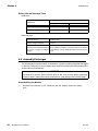
Measure the following voltages. Use TP 37 as ground reference.
Signal Name
Location
Side
Voltage
Tolerance
VDD
TP 43
Front
5.00 V
± 100 mV
+ VA
TP 31
Front
+ 13.75 V
± 500 mV
- VA
TP 40
Front
- 13.75 V
± 500 mV
+ CVA
IC 35 pin 2
Front
+ 12.00 V
± 500 mV
- CVA
IC 40 pin 3
Front
- 12.00 V
± 500 mV
+ VSRC
IC 38 pin 2
Front
+ 12.00 V
± 500 mV
- VSRC
IC 39 pin 3
Front
- 12.00 V
± 500 mV
VBATTADC
IC 37 pin 3
Front
+ 1.80 V
± 100 mV
VHTR
C148 Positive
Front
+ 8.00 V
± 1.00 V
CVREF
TP 24
Back
+ 2.50 V
± 25 mV
2CVREF
TP 23
Back
+ 5.00 V
± 50 mV
- 2CVREF
TP 26
Back
- 5.00 V
± 50 mV
VBACKUP
IC 8 pin 8
Front
+ 4.60 V
± 150 mV
LEDSRC
TP 45
Back
+ 11.50 V
± 1.00 V
6.
Monitor pin 4 of IC36 (or pin 5 of IC41) and insure that a 655 kHz sync frequency is
present. Check that pulse amplitude is switching between 0 and 5VDC.
7.
Monitor IC13-2 with an Oscilloscope. Verify a positive pulse 405 ± 10 us wide.
8.
Monitor IC14-2 with an Oscilloscope. Verify a positive pulse 393 ± 10 us wide.
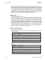
9.
Monitor Q5 pins 5-8 with an oscilloscope. Verify the following waveform:
+12V
-12V
828 us ± 40 us
32
Model 615 Service Manual
Rev. 00
Section 6
Electronic Tests
10.
Monitor Q6 pins 5-8 with an oscilloscope. Verify the following waveform:
+12V
-12V
828 us ± 40 us
11.
Enter the Configuration menus on the unit by pressing and holding the ADAPT
key immediately followed by the key.
E
12.
Press the key until CAPNOSTAT SERIAL # appears and VERIFY ACCURACY.
13.
Press and hold the
14.
Using a calibrated barometer, read the barometric pressure.
15.
Adjust VR1 (on the 2754 bd.) until the PB equals the actual barometric pressure ± 2.
16.
Cut the nasal cannula as shown below. Bond the 3/32" PVC tubing to each cut end,
then connect to the Y fitting. Connect the 1/8" PVC tubing to the to the output of the
Y fitting.
key.
Cut here, then connect
to flow meter via "T"
connector
6 ft tubing
Bond the PVC tubing to the cannula using a 50/50 mix of THF and Cyclohexanone.
Dip the cut cannula ends into the mix for one second, wipe off excess then connect
to the PVC tubing, allow to set for a period of five minutes. Verify there are no
occlusions.
Rev. 00
Model 615 Service Manua
33
Section 6
Electronic Tests
17.
Connect the cannula and dehumidification tubing to a sampling adapter as shown
below.
F low M eter
Y -fitting
C annula
Tubing supplied w ith cannula
S am pling adapter
D ehum idification tubing
18.
Attach the dehumidification tubing to the monitor (the CAPNOSTAT CO 2 sensor
should be connected to the adapter).
19.
Measure the voltage at J402 pin 1. Verify 0.00V ± 50mV.
20.
Press the Adapter key. Verify a Set Adapter Type menu is displayed.
21.
Press the Select key until Sampling is selected.
22.
Install a Single Patient Use Sampling Adapter and verify the sampling pump turns on
and the Flow Meter shows a flow rate of 180 ± 25 (adjusted by VR2).
23.
Measure the voltage at J402 pin 1. Verify 2.508V ± 75mV.
24.
Press the Zero key to start a Zero calibration. Verify an Adapter Zero in Progress
message is displayed with a timer counting down from 20. Verify the calibration
completes with no error messages present.
25.
Remove the Sampling Adapter and verify the pump turns off.
26.
Press the Adapter key. Verify the Set Adapter Type menu is displayed.
27.
Press the Select key until Adult is selected. Press the Exit key. Verify the sampling
pump turns off and the main screen is displayed.
28.
The test is complete.
6.3 Safety Testing
1.
Using a leakage tester, and with the external DC power supply connected, measure
the leakage current:
• Normal
• Normal reverse ground
• Normal ungrounded
Verify a leakage current <300 uA for 120VAC or <500 uA for 220VAC.
34
Model 615 Service Manual
Rev. 00
Section 7
Status Messages
Status messages indicate conditions that should be corrected or monitored; they may or may
not be tied to an alert condition. These conditions can be a result of a hardware or sensor fault
condition. Status messages are displayed on the screen in the same manner as alert
messages. Following is a list of status and alert messages that may appear on the monitor.
7.1 System Messages
Message
Description
PRESSURE FAULTY The barometric pressure sensor is returning a value which is out of
range (<400 mmHg or > 800 mmHg). The monitor will default to 760
mmHg for calculation purposes. Refer servicing to qualified personnel.
EtCO2 AUTO LIMITS This message is displayed when the monitor has successfully deterSET
mined and set the auto alert limits for ETCO2.
RESETTING TO
FACTORY
DEFAULTS
TRENDS ERASED
All setup and alert settings have just been reset to factory default values.
The trends stored in the monitor’s memory have been erased.
CHECK TIME/DATE Time and date may not be properly set. The time and date can be
adjusted in the CONFIGURATION menu by pressing the
light key.
Back-
UNKNOWN ERROR Remove the monitor from use and contact Novametrix service personnel.
7.2 Capnography Messages
Rev. 00
Message
Description
CAPNO
WARMING
Sensor is under temperature. Wait for the CAPNOSTAT® CO2
sensor to reach operating temperature.
Model 615 Service Manua
35
Section 7
Status Messages
Message
Description
CHECK
ADAPTER
Excessive moisture or secretions detected in the adapter:
Change adapter.
Adapter type has been changed (e.g. adult to neonatal): Zero
the adapter.
No adapter detected: Place an adapter on the CAPNOSTAT®
CO2 sensor.
RESP=0
m : ss
A breath has not been detected for the indicated time (XX seconds). This message appears when the time since the end of
expiration of the last detected breath exceeds the NO RESP
TIMER setting in the configuration menu.
INSP
XX
An inspired CO2 level of 3 mmHg (or 0.4% or kPa) was
detected for 20 consecutive seconds.
ZRO: HOLD
ADPT KEY
The current through the CAPNOSTAT® CO2 sensor source
emitter has changed or the system is detecting EtCO2 values
less than -3.0 mmHg.
CAPNO FAULTY
The following errors may be present:
1. The current through the source is too high or low.
2. The checksum for the CAPNOSTAT® calibration data is
wrong.
3. The revision of the calibration data in the CAPNOSTAT® is
not compatible with the software in the TIDAL WAVE Sp Monitor.
Refer servicing to qualified personnel.
CAPNO
HI TEMP
The temperature of the case or detector heater is over 50°C.
Refer servicing to qualified personnel.
CAN NOT
ZERO CO2
An error was detected which did not allow the system to zero
the current adapter being used. Refer servicing to qualified personnel.
CO2 OUT
OF RANGE
The detected waveform value is beyond the measurement
range of the monitor (0-100 mmHg, 0-13.2% or kPa).
A changing level of CO2 was detected during an adapter zero
procedure. Wait 30 seconds and retry.
The CAPNOSTAT® CO2 sensor has not reached operating
temperature while attempting to zero. Wait for the sensor to
reach operating
temperature.
36
ADAPTER ZERO
IN PROGRESS,
TIME REMAINING 0 : XX
An airway adapter zero is in progress. XX indicates the number
of seconds remaining.
WARNING:
CHANGING CO2 UNITS
ERASES STORE
TRENDS
Changing CO2 units (mmHg, %, kPa) in the Configuration
menu will cause this message to appear.
Model 615 Service Manual
Rev. 00
Section 8
Maintenance
8.1 General
This section presents recommended maintenance schedules for the Model 615 and information
on general maintenance, such as battery and fuse replacement, disassembly and assembly
instructions, and system software updates.
8.2 Maintenance Schedules
When the monitor powers up, a self-test is performed which checks the internal electronics of
the monitor. If this self-test fails, remove the monitor from use and contact qualified service
personnel.
The monitor should undergo routine inspection and safety checks on a quarterly basis or
according to hospital protocol.
The electronic circuits within the Model 615 handheld capnograph do not require scheduled
calibration or service. However, in order to maximize battery life, the monitor’s internal battery
should be tested monthly. Novametrix recommends the following maintenance schedules.1
• Cleaning and Sterilization:
Perform as required. See "Cleaning and Sterilization" on page 38.
• Battery and AC Operation:
Contains information on rechargeable batteries. See "Battery Maintenance" on page 39.
• Functional Tests:
The test verifies overall functional integrity of the monitor and sensor. See "Functional
Tests" on page 23.
• Accuracy Tests:
The test verifies the calibration accuracy of the monitor using specified test apparatus. See
"Accuracy Tests" on page 27.
• Electronic Tests:
These tests contain information on testing the electronic circuits within the Model 615 and
should only be performed if the monitor fails to pass the Functional Tests. Only qualified
service personnel should attempt to perform the Electronic Tests. See "Electronic Tests"
on page 31.
1. At the customer’s request, Novametrix will provide repair and calibration services under terms of a Service Contract. Contact the
Novametrix Service Department for contract details.
Rev. 00
Model 615 Service Manua
37
Section 8
Maintenance
8.3 Cleaning and Sterilization
Follow the cleaning and sterilization instructions listed below to clean and/or sterilize the
monitor and its accessories.
Monitor, BaseStation and External Power Supply
• Turn the monitor off, and unplug the BaseStation and the external power supply from the
AC power source before cleaning.
• The monitor, BaseStation and external power supply can be cleaned and disinfected with
solutions such as a 70% isopropyl alcohol, 2% glutheralhyde, or 10% bleach solution. Wipe
down with a water-dampened clean cloth to rinse. Dry before use.
• Do not immerse the monitor, BaseStation or external power supply.
• Do not attempt to sterilize the monitor, BaseStation or external power supply.
CAPNOSTAT® CO2 Sensor
• Clean the sensor surface with a damp cloth.
• Make certain that the sensor windows are clean and dry.
• Do not immerse the CAPNOSTAT® CO2 sensor.
• Do not attempt to sterilize the CAPNOSTAT® CO2 sensor.
Single Patient Use Airway Adapters
• Treat all single patient use airway adapters in accordance with hospital protocol for singlepatient use items.
External Sampling System Components
• The Nasal Sampling Cannulas and adapters are for single-patient use.
Internal Sampling System Components
Acceptable fluids for cleaning and sterilizing the internal pneumatic parts of the Sampling
System include isopropyl alcohol, Cidex2 or equivalent, or a 5.25% water solution by weight of
sodium hypochlorite (bleach).
CAUTION
Do not attempt to pump cleaning/sterilizing liquid with the sampling pump. This may cause
accelerated wear on the pump bearings. Always flush liquids with a syringe as described in
the following instructions.
To clean and disinfect the pumping system:
1.
Turn the monitor off and disconnect the external power supply (if connected).
2.
Remove both the sampling inlet tubing set and the sampling exhaust tubing (if any).
2. Cidex is a trademark of Arbook, Inc.
38
Model 615 Service Manual
Rev. 00
Section 8
Maintenance
3.
Attach an exhaust port line (1/8 inch or 3/16 inch I.D. tubing) from the Sampling
Exhaust
port to a suitable container located below the bottom level of the
monitor.
4.
Use a 60 cc catheter tip syringe. Fit it to the Sampling Inlet
connector. Flush the
sterilizing solution slowly through the pumping system. Push the entire 60 cc of
solution through the Sampling Inlet
. Repeat this process two more times to use
a total of 180 cc of solution.
5.
Remove the syringe and leave the cleaning/sterilizing fluid within the sampling pump
system for 30 minutes to disinfect the system. Follow sterilant manufacturer’s
instructions for disinfection.
6.
After 30 minutes, fill the syringe with distilled water and flush the system three times.
Allow the cleaning/disinfection solution and distilled water to drain through the
Sampling Exhaust
output.
7.
Push several syringes of air slowly through the system to ensure that most of the
liquid has been drained.
8.
Follow this with at least three more syringes of distilled water, followed by at least two
more syringes of air to make sure that most of the distilled water has been drained.
9.
Remove the syringe from the unit. Do not connect the sampling inlet tubing. Connect
the external power supply and turn the monitor on. Allow the sampling pump to
operate for several minutes. This will help to remove any trapped water.
10.
Connect a sampling tubing set to the Sampling Inlet .
11.
Block the open end of the tubing with your finger. Alternate blocking and unblocking
the tubing end at least ten times. Use a quick, brisk motion when blocking and
unblocking the tubing. Keep the tubing blocked and unblocked for several seconds
at a time.
12.
Repeat the same blocking and unblocking action with your finger on the sampling
exhaust
port.
13.
Allow the sampling system to run for at least 30 minutes without the sampling
assembly tubing and the sampling exhaust tubing connected. This will speed dry the
system pneumatics.
14.
Once these cleaning and disinfection instructions have been completed, normal
sampling system operation can be resumed.
8.4 Battery Maintenance
New batteries, or batteries stored for extended periods of time (3 months or more) may need to
be fully charged and discharged up to five (5) times before performing at full capacity. New
batteries or batteries that have not been used for 30 days, should be charged for 24 hours prior
to use.
AC/Battery Operation
The monitor can operate for up to 4 hours while powered from a fully charged internal battery.
The battery is charging when the monitor is powered through its DC input and
the
keypanel
icon is green. The battery will charge even if the monitor is off. Power to the DC input is supplied
Rev. 00
Model 615 Service Manua
39
Section 8
Maintenance
by the external power supply (Cat. No. 9220-10) with or without the optional BaseStation (Cat.
No. 6998-00).
Rechargeable and disposable battery capacity is shown in the table titled, " Battery Life and
Recharge Times" on page 44. Times may be reduced in colder temperatures or with the
sampling adapter; operation with the backlight off may slightly increase these times.
Battery Status and Alerts
When the monitor is operating on battery power, and the battery is sufficiently charged, the
battery icon LED
on the keypanel will be green. The battery level is reflected on the battery
icon by different colors (for example, battery fully charged: green, battery low: flashing yellow).
The LED on the keypanel flashes red when the monitor is powered by its internal battery and
approximately 5 minutes remain. The monitor will sound an audible alert, then when the battery
is depleted, turn itself off. This alert can only be silenced by connecting the external supply or
turning the monitor off. The NiMH battery pack should be replaced, or th Model 615 BaseStation
(Cat. No. 6998-00) or external power supply (Cat. No. 9220-10) should be connected to recharge
the battery (rechargeable batteries only) and power the monitor. See "Battery Life and Recharge
Times" on page 44.
NOTE
When the battery is low (red blinking battery LED
on keypanel) the monitor has shut
down CO2 functions. Connect to AC power as soon as possible.
NOTE
The battery life indicator may not reflect the true battery status upon power-up for
approximately 30 seconds.
The battery life indicator is inactive when the monitor is powered by the BaseStation or the
external power supply.
40
Model 615 Service Manual
Rev. 00
Section 8
Maintenance
Removing and Installing the Battery
Grasp the finger grips on each end of the battery cover. Squeeze together and pull so that the
cover opens to reveal the internal battery (the cover is hinged on the bottom of the case).
Remove the battery from the monitor.
Finger grip
Power jack
Hinged side
Interface connector
WARNING: Do NOT connect to any device not
approved by Novametrix
Battery cover
The battery is keyed so that it can be installed in only one way (see illustration inside battery
compartment). The contacts should go in first and be located toward the top left of the monitor
when inserting. Make certain the battery cover is properly closed before operating the monitor.
Charge using External Power Supply
Plug the external power supply directly into the DC power jack on the side of the monitor, and
connect a hospital-grade line cord to an AC source. The AC icon
will illuminate green and
the battery will charge in approximately 5.5 hours. If the monitor has been stored with the
battery installed for thirty (30) days or more, charge the battery for 24 hours prior to use.
DC input
Connect line cord
(Cat. No. 600075)
External power supply
(Cat. No. 9220-10)
CAUTION
Use only Novametrix supplied devices when connecting to the power input jacks on the
Model 615 or on the BaseStation.
Do not attempt to use the adapter for the external battery charger for this function.
Rev. 00
Model 615 Service Manua
41
Section 8
Maintenance
NOTE
When powered by the external power supply, the Model 615 will not overcharge a
rechargeable battery.
The external power supply has a universal power input. The IEC 320 input receptacle for line
cord connection allows compatibility with ever y countr y’s voltage and frequency
requirements.
Charge using optional BaseStation
Power for the BaseStation is supplied by an external power supply (Cat. No. 9220-10) or the
internal battery. When the power supply is properly connected to the BaseStation and a monitor
is placed within the station the green, “In Use” LED will illuminate. The
icon on the monitor
will also illuminate indicating that external power is connected.
Connect the external power supply jack to the monitor and connect a hospital-grade line cord
from the external power supply to an AC source.
The 9220-10 Power Supply is approved
by the following regulatory agencies:
Monitor in BaseStation
(BaseStation Cat. No. 6998-00)
:Canadian Standards Assoc.
:SEMKO (Sweden)
V
D E
DC input
:VDE (Germany)
FI :FINKO (Finland)
D :DEMKO (Denmark)
Connect line cord
IEC 320 receptacle
(Cat. No. 600075)
External power supply
(Cat. No. 9220-10)
Illuminates indicating
external power
Green “In Use” LED illuminates indicating
a monitor is in place and the power supply
is active
CAUTION
Although other connectors may physically fit, do not attempt to connect any device other than
power supplies approved by Novametrix for use with this device. Doing so may damage the
Model 615 and will void the warranty.
Never sterilize or immerse the monitor, sensor or accessories in liquids.
Charging with External Charger
In a non-patient area, connect the adapter to an AC source, then plug the adapter jack into the
charger. Remove the battery from the Model 615 and insert it into the external charger. The
battery will be fully charged in approximately 4.5 hours. The external charger is for use with the
42
Model 615 Service Manual
Rev. 00
Section 8
Maintenance
NiMH rechargeable battery pack (Cat. No. 400043) only. Refer to the instructions supplied with
the charger for additional information.
NiMH Rechargeable Battery
(Cat. No. 400043)
Connect adapter
Battery is keyed
to fit into slot in
only one direction
Connect line cord
WARNING
The external battery charger should NOT be used to recharge the battery near or in close
proximity to patients and/or other medical equipment in operation. It is intended for use in
service areas only (i.e. nurses station, biomed lab, etc.).
NOTE
With a new battery, or a battery that has not been used for 30 days or more, charge the
battery for 24 hours prior to use.
When powered by the external power supply or the BaseStation, the Model 615 will not
overcharge a rechargeable battery.
The monitor may not operate on battery power if the battery is not sufficiently charged.
Dispose of batteries in accordance with local laws.
AA Lithium Batteries
To power Model 615 from AA lithium batteries, insert seven disposable batteries (Energizer L91
or equivalent) into the optional Battery Case (Cat. No. 6862-00) following the polarity markings
on the Battery Case.
WARNING
Batteries can explode, leak or catch on fire if heated or exposed to fire or high
temperatures.
Do not mix battery types (e.g. disposable and rechargeable AA batteries).
Rev. 00
Model 615 Service Manua
43
Section 8
Maintenance
Battery Life and Recharge Times
Battery life:
Power source - Approximate Monitoring Times
Configuration
Rechargeable NiMH
AA lithium batteries
CO2 only (sampling off)
4.5 hours
4.0 hours
CO2 with sampling
4.0 hours
3.5 hours
Recharge times:
Recharge method
Recharge times
External charger w/adapter
4.5 hours
External power supply or
External power supply/BaseStation
(in monitor using wall adapter
charger)
5.5 hours - following recent use of more than approximately
4 hours. With a new battery, or a battery that has not been in
use for 30 days or more, charge the battery for 24 hours prior
to use.
8.5 Assembly Exchanges
The disassembly instructions below are intended as a guide to enable component exchanges
if necessary. There are no user serviceable parts inside. Disassembly should be performed by
qualified service personnel only.
CAUTION
The Model 615 contains static sensitive devices. Be sure to follow proper grounding
procedures when handling the internal components to avoid damage from static discharge.
Disassembling the Monitor
1.
44
Ensure that the monitor is OFF. Disconnect the A/C adapter, remove the battery
pack.
Model 615 Service Manual
Rev. 00
Section 8
Maintenance
2.
Turn the monitor upside down and remove the four cover screws from the bottom
cover.
cover screws
3.
Carefully lift the rear cover from the monitor. The separate assemblies of the monitor
can now be removed.
4.
Lift the Main Board and disconnect ribbon cable from the Sensor Assembly Board by
grasping the connector (not the cable) and gently rocking from side to side to loosen.
Be careful not to bend any pins when pulling the connector off of the header strips.
main board
ribbon cable
side view
Unplug the pump connector from the main board.
Rev. 00
5.
Remove the Main Board.
6.
The Sensor Assembly Board, Display Board, and battery connector can now be
accessed.
Model 615 Service Manua
45
Section 8
Maintenance
7.
To disconnect ribbon cable J3, grasp the edge of the ZIF (zero insertion force)
connector with one forefinger on either side. Pull gentl sideways to release the
mechanism. Slide the ribbon cable out.
ZIF connector
8.
Remove four screws from the Sensor Assembly Board, then the screw near the
battery connector.
sensor assembly
board screws
battery connector screw
9.
46
Remove the sensor assembly board by gently prying upward, rocking gently to
release the header strip J1 which connects through the Sensor Assembly Board from
the Display Board below.
Model 615 Service Manual
Rev. 00
Section 8
Maintenance
10.
Remove 4 screws holding the Display Board in place. Do not bend the tabs on the
board, the LCD display can not be removed from the board. Be sure not to lose the
plastic bezel located in between the LCD display and the display window.
display board
screws
ribbon cable
Reassembling the monitor
1.
Check the inside of the display window and the LCD display for dirt/finger prints,
clean if necessary. Replace the plastic bezel around the display window. Set the
Display Board in place and secure with 4 screws.
2.
Slide the ribbon cable through the sensor assembly board, align the Sensor
Assembly board’s J2 connector to the header strip on the display board. Check that
the battery connector is aligned to the cover’s receptacle. Just before pressing the
Sensor Assembly Board into place, use a small screwdriver to set the ground strap
from the keypanel into place.
3.
Secure the Sensor Assembly Board with 4 screws. Then secure the ground strap
with a screw
4.
Slide ribbon cable J3 into the ZIF locking connector, pushing gently to be sure that
the cable is as far into the locking mechanism as possible. Push the connector closed
to lock in the ribbon cable. Pull lightly on the ribbon cable to ensure that it is secure.
5.
Replace the three connections from the Main Board to the Sensor Assembly Board
and align the main board with the standoffs.
6.
Ensure the battery gasket is set in place, refer to the assembly print 6800-01 (page
3) for placement. Place the back cover on the monitor. Secure with 4 screws.
7.
Opened hinged cover and replace the rechargeable battery or battery pack. Battery
is keyed to fit in only one direction. When the monitor is powered it will default to the
factory default settings.
8.6 Serial Communications/Power Interface Connector
Located on the enclosure rear is a six pin modular contact which provides an RS232 interface
as well as a power input for unit operation and battery charging when connected to Novametrix
accessories. This connector meets the patient safety requirements of the following agencies:
IEC 601-1, UL544, and TUV.
Rev. 00
Model 615 Service Manua
47
Section 8
Maintenance
8.7 Software Update Instructions
The following procedure is for updating the monitor’s software from a supplied Model 615
Software Update Kit using an IBM-compatible computer and the Base Station (Cat. No. 699800). Refer to any instructions that may accompany the software update diskettes for changes
in the procedure or other pertinent information.
Equipment Required
1.
IBM compatible computer with an unused serial port (COM1 or COM2)
2.
Base Station (Cat. No. 6998-00)
3.
Serial Communication Cable (PN: 211923)
4.
Update diskette PN: 9475-07-XX (XX = new firmware version)
5.
Reply card
Setup
Connect the serial cable to the Base Station. Connect the other end of the cable to the
computer’s COM3 (serial) port. The update software allows use of either COM1 or COM2.
When connecting the cable be sure to record which COM port is used, the program will prompt
the user for this information before updating the software.
Procedure
Turn the Model 615 off, then place it into the base station. Remove the AC adapter/charger
connector from the base station if installed. NOTE: All power to the Model 615 must be removed
otherwise the update will not operate properly.
Insert the update diskette into the computer’s floppy drive (typically drive A).
(where A is the drive letter where the update diskette is loaded). At
From DOS: Type A:
the “A:” prompt type UPDATE then press
.
From Windows 3.x: Boot to DOS and follow the DOS instruction above.
From Windows 9X/2000/NT: Select Start, Run, then type A:update
letter where the update diskette is loaded)
(where A is the drive
Follow the install program screen instructions. Verify that the firmware version shown on the
computer screen is correct, then press any key to continue.
3. The location and availability of the COM ports (COM1, COM2) will vary from computer to computer. Refer to the computer’s docu mentation for more information. The update software can only communicate with the Model 615 through either COM1 or COM2.
48
Model 615 Service Manual
Rev. 00
Section 8
Maintenance
When the following prompt appears:
Select the PC’s COM port the instrument is connected to
from the following choices:
1-COM1
2-COM2
any other key - exit
Press the 1 key if the serial communications cable is connected to COM 1.
Press the 2 key if the serial communications cable is connected to COM2.
If you are not sure of the process, press any other key and call service or Novametrix Service
Department at 1-800-243-3444, in Connecticut call collect (203) 265-7701.
Turn the Model 615 on (connect the AC adapter/charger to the base station if the battery is not
fully charged). It is important that the Model 615 is powered off when the update program is
started, and is turned on after the program starts to access the monitor.
When the download starts the Model 615 screen will blank and the following message wil
appear on the computer screen.
Validating File
then,
UPDATING FIRMWARE, DO NOT INTERRUPT. PERCENT DONE: xx%
The “xx” will count up from 0% through 100% as the update is completed.
The procedure is complete when the computer displays:
***PROGRAM COMPLETE***
F1-exit
Esc-back
Press F1 to exit the update program.
Check that the Model 615 restarts and returns to normal operation, if not then perform the
update procedure again or call Novametrix Service Department at 1-800-243-3444, in
Connecticut call collect (203) 265-7701.
Record the serial number from the Model 615 on the reply card (supplied with software update
disk). Fill in the remaining information and return the postage paid card to Novametrix.
Rev. 00
Model 615 Service Manua
49
Section 8
Maintenance
[This page intentionally blank.]
50
Model 615 Service Manual
Rev. 00
Warranty
Equipment manufactured or distributed by Novametrix Medical Systems Inc., is fully
guaranteed, covering materials and workmanship, for a period of one year from the date of
shipment, except for certain disposable products and products with stated guarantees other
than one year. Novametrix reserves the right to perform guarantee service(s) at its factory, at
an authorized repair station, or at the customer’s installation.
Novametrix’ obligations under this guarantee are limited to repairs, or at Novametrix’ option,
replacement of any defective parts of our equipment, except fuses, batteries, and calibration
gasses, without charge, if said defects occur during normal service.
Claims for damages during shipment must be filed promptly with the transportation company.
All correspondence concerning the equipment must specify both the model name and number,
and the serial number as it appears on the equipment.
Improper use, mishandling, tampering with, or operation of the equipment without following
specific operating instructions will void this guarantee and release Novametrix from any further
guarantee obligations.
Service Department
For factory repair service, call toll free
1-800-243-3444
In Connecticut, call Collect (203) 265-7701
Facsimile (203) 284-0753
World Wide Web: http://www.novametrix.com
Internet: [email protected]
Caution: Federal (U.S.A.) law restricts this device to sale, distribution, or use by or on the order
of a licensed medical practitioner.
Rev. 00
Model 615 Service Manua
51
Service Policy
Novametrix Medical Systems Inc. provides 24-hour a day access to technical support through
its Technical Support Department in Wallingford, Connecticut, and company Service
Representatives located throughout the United States. (Outside the U.S., primary technica
support is handled through our qualified international sales and service distributors.)
Novametrix will provide Warranty Service support within 48 hours of receiving a request for
assistance. Contact the Technical Support Department by telephone toll free at 800-243-3444,
or 203-265-7701; by facsimile at 203-284-0753; or, by e-mail at [email protected].
After hours telephone support requests (before 8:00 AM and after 5:00 PM Eastern Time) will
be responded to promptly by the Technical Support on-call staff. After hours facsimile and email requests will be answered the next business day. It is suggested that any person calling in
for technical support have the equipment available for product identification and preliminary
troubleshooting.
Novametrix reserves the right to repair or replace any product found to be defective during the
warranty period. Repair may be provided in the form of replacement exchange parts or
accessories, on-site technical repair assistance or complete system exchanges. Repairs
provided due to product abuse or misuse will be considered “non-warranty” and invoiced at the
prevailing service rate. Replaced or exchanged materials are expected to be returned to
Novametrix within 10 days in order to avoid (additional) charges. Return materials should be
cleaned as necessary and sent directly to Novametrix using the return paperwork and shipping
label(s) provided (Transferring return materials to a local sales or dealer representatives does
not absolve you of your return responsibility.).
Novametrix manufactures equipment that is generally field serviceable. When repair parts are
provided, the recipient can call Technical Support for parts replacement assistance and repair
assurance. In the event a replacement part requires increased technical capability, Technical
Support may request Biomedical assistance, provide on-site technical support or complete
replacement equipment. If the customer requires the return of their original product, the
exchange material will be considered “loaner material” and exchanged again after the customer
equipment is repaired.
Novametrix promotes customer participation in warranty repairs, should they become
necessary. A longer useful product life, and quicker, more cost-effective maintenance and
repair cycles—both during and after the warranty period, are benefits of a smooth transition into
self-maintenance. The Technical Support Department can provide technical product support at
a level appropriate to your protocol and budget requirements.
Please contact Technical Support for information on these additional programs and services:
• Focus Series Technical Training Seminars
• Test Equipment and Test Kits
• Service Contract / Parts Insurance Plans
• On-Site Technical Support
• “Demand Services” including:
Flat rate parts exchange
Flat rate return for repair
Time and material,
Full warranty, discounted replacement sensors.
52
Model 615 Service Manual
Rev. 00
Section 9
Specifications
Section 9
Specifications
9.1 Specifications
General
Specifications for the Novametrix Model 615, are listed for informational purposes only, and are
subject to change without notice.
Capnograph
• Principle of Operation: Non-Dispersive Infrared (NDIR) absorption, dual wavelength
ratiometric-single beam optics
• Sensor Type: “Mainstream” (no gas sample drawn from breathing circuit)
• Initialization Time: Capnogram in 15 seconds, full specifications in 60 seconds.
• Response Time: 60 ms
• Gas Compensation - Room Air, O2 > 60%, N20 > 60%: Operator selectable in configuration
screen.
• Barometric Pressure Compensation: Automatic (range 400-800 mmHg)
• CAPNOSTAT® CO2 Sensor and Airway Adapter:
Weight: Less than 18 g without cable
Sensor Size: 1.30" x 1.67" x .85" (3.30 x 4.24 x 2.16 cm), 6 foot cable (2.44 m)
Construction: Durable high performance plastic, ultra-flexible cable
Shock Resistant: Sensor will withstand a 6 foot drop to a tile floor
• Airway Adapter: Single Patient Use, less than 5 cc deadspace, meets ANSI Z-79
EtCO2 Section (Mainstream)
• Range 0-150 mmHg, CO2 partial pressure
• Accuracy1: 0-40 mmHg ±2 mmHg, 41-70 mmHg 5% of reading, 70-150 mmHg ±8% of
reading.
• Warm-up Time: Operational in 15 seconds, 1 minute to full specifications
• Step Response Time: 60 ms, adult; less than 50 ms, neonate
• Averaging Time: 1 breath, 10 seconds (default), 20 seconds, instantaneous
• Display Resolution: 0-25, 0-50, and 0-150 mmHg in 31 pixels
• Alerts: The Model 615 has user selectable alert limits for EtCO2.
Respiratory Rate (Mainstream)
•
•
•
•
Range 0-150 breaths/min.
Accuracy: ±1 breaths/min.
Alerts: The Model 615 will have user selectable alert limits for Respiratory Rate.
Averaging Time: 8 seconds
1. Allows for halogenated anesthetic agents which may be present at normal clinical levels. The presence of desfluane in the
exhaled breath beyond normal levels (5-6%) may positively bias Carbon Dioxide values by up to an additional 2-3 mmHg.
Rev. 00
Model 615 Service Manua
53
Section 9
Specifications
EtCO2 Section (Sidestream)
• Range 0-150 mmHg, CO2 partial pressure
• Accuracy: 0-40 mmHg ±2 mmHg, 41-70 mmHg 5% of reading, 70-150 mmHg ±8% of
reading.
• Warm-up Time: Operational in 15 seconds, 1 minute to full specifications
• Step Response Time: less than 200 ms; Sampling Rate - 180 cc/min.
• Averaging Time: 1 breath, 10 seconds (default), 20 seconds, instantaneous
• Display Resolution: 0-25, 0-50, and 0-150 mmHg in 31 pixels
• Alerts: The Model 615 will have user selectable alert limits for EtCO2.
Respiratory Rate (Sidestream)
•
•
•
•
Range 0-70 breaths/min
Accuracy: ±1 breaths/min.
Alerts: The Model 615 will have user selectable alert limits for Respiratory Rate.
Averaging Time: 8 seconds
9.2 Monitor Specifications
• Classification (IEC601-1): Class II/internal power source, type BF, enclosure protection
rating of IPX12. Operating Environment: 50 to 104° F (10 to 40° C), 0-90% relative humidity
(non-condensing)
• Transport/Storage:
short term: 14° to 122° F (-10° to 50° C) with NiMH battery
long term: 14° to 95° F (-10° to 35° C) with NiMH battery
storage: 14° to 131° F (-10° to 55° C) without NiMH battery
• Size: 7.9” x 3.25” x 1.5”
• Weight: 24 ounces
• Power: 100-250 VAC, .38A, 50-60 Hz
• Battery: Rechargeable NiMH battery pack (Cat. No. 400043) or equivalent; AA lithium
batteries - Energizer L91 or equivalent.
• Battery Life: Approximately 4.5 hours of continuous use with fully charged NiMH
rechargeable battery pack. Approximately 4.0 hours with sample pump in operation.
• Display: LED backlit 2.5” x 1.25” LCD, adjustable contrast
• LED indicators for: Low battery, adapter type, audio/alert status (indicates audio off, 2
minute silence, active alert), and external power.
• Electromagnetic Emissions: Conforms to EMC Directive 89/336/EEC, CISPR Class A.
Tested to EN55011 (1991) and CISPR11 (1990).
• Electromagnetic Immunity: Conforms to EMC Directive 89/336/EEC, EN50082-1 (1992).
Tested to IEC801-3 (1984) Radiated Immunity. Conforms to Medical Device Directive 93/
42/EEC and EN60601-1-2 (1993). Tested to IEC801-2 (1991) ESD, IEC801-4 (1988) EFT,
and IEC1000-4-5 (1995) Surge Immunity.
2. External power supply excluded.
54
Model 615 Service Manual
Rev. 00
Section 9
Specifications
Additional Features
• Alert Limits: Automatic or menu selected high and low limits for ETCO2 and Respiratory
Rate. NO RESPIRATION alert selectable between 20, 40 and 60 seconds. Visible and
audible alerts are immediate.
• 2-Minute Silence: When
key is pressed, audible alerts are deactivated for two minutes.
Indicated by yellow 2 minute LED and flashing
bell icon
• Audio Off: Press and hold
key for 3 seconds to deactivate audible alerts. Indicated by
flashing yellow Audio Off LED and flashing
bell icon.
• Trend Memory: 24 hour trend memory capacity, battery backed. On-screen 30 minute
trends for ETCO2 and Respiration Rate. Other parameters are stored internally and can be
downloaded to a PC.
• Digital Data Output: Serial (RS232), connect only to Novametrix approved devices.
• Sampling System: Standard. Allows gas sampling of non-intubated patients
• Internal Battery-backed Real Time Clock
Rev. 00
Model 615 Service Manua
55
Section 9
Specifications
[This page intentionally blank.]
56
Model 615 Service Manual
Rev. 00
Section 10
Accessories
Section 10
Catalog No.
9425-00
Accessories
Description
TIDAL WAVE Handheld Mainstream Capnograph and Sidestream Sampling (Model
615) includes Single Patient Use Adult Airway Adapter (6063-01), Carrying Case (315127),
and Single Patient Use Sampling Adapter with Adult Nasal CO2 Sampling Cannula (8955
01).
CO2 AIRWAY ADAPTERS and ACCESSORIES
For monitoring CO2 with the CAPNOSTAT ® CO2 sensor.
6063-00
Pediatric/Adult Single Patient Use Airway Adapters (10 per box
6063-25
Pediatric/Adult Single Patient Use Airway Adapters (25 per box
6421-00
Pediatric/Adult Single Patient Use Airway Adapters with mouthpiece (10 per box)
6421-25
Pediatric/Adult Single Patient Use Airway Adapters with mouthpiece (25 per box)
6312-00
Neonatal/Pediatric Single Patient Use Airway Adapters (10 per box)
6312-25
Neonatal/Pediatric Single Patient Use Airway Adapters (25 per box)
SAMPLING ADAPTERS and ACCESSORIES
8954-00
Single Patient Use Sampling Adapters (10 per box)
8954-25
Single Patient Use Sampling Adapters (25 per box)
8955-00
Single Patient Use Adapter w/ Nasal CO2 Sampling Cannula—Adult (10 per box)
8955-25
Single Patient Use Adapter w/ Nasal CO2 Sampling Cannula—Adult (25 per box)
8956-00
Single Patient Use Adapter w/ Nasal CO2 Sampling Cannula—Pediatric (10 per box)
8956-25
Single Patient Use Adapter w/ Nasal CO2 Sampling Cannula—Pediatric (25 per box)
8957-00
Single Patient Use Adapter w/ Nasal CO2 Sampling and O2 Delivery Cannula—Adult
(10 per box
8957-25
Single Patient Use Adapter w/ Nasal CO2 Sampling and O2 Delivery Cannula—Adult
(25 per box
8958-00
Single Patient Use Adapter w/ Nasal CO2 Sampling and O2 Delivery Cannula—
Pediatric (10/box)
8958-25
Single Patient Use Adapter w/ Nasal CO2 Sampling and O2 Delivery Cannula—
Pediatric (25/box)
8908-00
Nafion® Dehumidification Tubing (10 per box)
POWER SUPPLY OPTIONS
6998-00
BaseStation (External Power Supply and/or computer cable not included
9220-10
External DC Power Supply (power cord not included
6862-00
AA Lithium Battery Pack (requires 7 batteries)
400050
AA Lithium Battery (7 required)
400043
NiMH Rechargeable Battery
400049
Battery Charger, w/ AC Adapter, Universal Input Voltage, for type DR30 NiMH battery. Power
cord included
MISCELLANEOUS
140084
Pole/shelf mount kit
315127
Transport Pouch
6065-00
600026
Rev. 00
NovaCARD for Window , Data Archive Software (3½” diskette)
Power Cord (N. America only
Model 615 Service Manua
57
Section 10
Accessories
Catalog No.
600075
58
Model 615 Service Manual
Description
Cable, BaseStation to Personal Computer (with 9-pin connector)
9086-00
Cable, BaseStation to Seiko DPU-414 Printer
9140-00
Seiko DPU-414 Thermal Printer w/Batter
400052
AC Adapter for Seiko DPU-414 Printe , 120 VAC
300017
Thermal Printing Pape , Seiko DPU-414 (5 rolls per box
6081-00
Gas regulator, for use with precision gas mixture, Cat. No. 8364-10
8364-10
Precision gas mixture for validation
Rev. 00
Parts Lists
Final Assembly 9425-00, Model 615
Seq
Item Nbr Description
Quantity
001
6874-32
LABEL, SN & BTRY
1
002
6886-13
CARTON, SHIPPING
1
004
9026-32
LABEL, "MANUFACTURED IN USA"
1
005
9425-01
MAIN ASSY, 615
1
007
9425-09
OVERALL WIRING DIAGRAM
0
008
9425-23
USERS MANUAL
0
013
9409-32
LABEL, QUICK GUIDE
1
014
9341-32
WARN LABEL, AC PWR SUPPLY
1
020
160044
ALCOHOL, ISOPROPYL
0
Seq
Item Nbr
Description
001
2754-01
MAIN BOARD ASSY, 615
1
002
6680-26
BOTTOM CVR W PAD PRINTING
1
003
6685-16
BATTERY DOOR
1
004
6823-10
FILLER, KEYPANEL
1
005
6838-10
GASKET
1
Main Assembly 9425-01, Model 615
Rev. 00
Quantity
006
6839-10
GASKET
1
007
9422-27
MEMBRANE KEYPANEL, 615
1
008
9426-13
TOP COVER W PAD PRINTING,
1
009
9203-10
INSULATING SHIELD
1
010
9208-01
XDUCER ASSY, CAPNO II
1
011
9215-01
END PANEL ASSY
1
012
9187-10
FOAM PAD, TOP
1
013
9201-10
FOAM PAD, BOTTOM
1
016
160044
ALCOHOL, ISOPROPYL
0
017
161102
ADHESIVE, RTV162, SILICON
0
018
281211
SCREW, 2-56 X 1/4L
0
019
286223
SCREW, 6-32 x 3/8 IN
0
Model 615 Service Manua
59
Main Assembly 9425-01, Model 615
Seq
Item Nbr
Description
Quantity
020
482605
LCD DISPLAY
1
021
600076
RIBBON CABLE, 60 PIN
1
022
250166
PUMP
1
023
282024
SCREW, M2 X .4 X 8MM L
2
024
285050
SHOULDER WASHER, NYLON
2
025
161108
FOAM TAPE, 1/32THK x 3/4W
0
Seq
Item Nbr
Description
000
487100
IC, TC1426COA
1
000
475052
POTENTIOMETER, 1K OHM
1
000
474245
RESISTOR, 1M OHM, 1/16W,
6
000
213900
CONNECTOR, 60 PIN, HEADER
1
000
154106
CAPACITOR, 22PF, 50VD
2
000
474241
RESISTOR, 150K OHM, 1/16W
6
Main Board Assy 2754-01, Model 615
60
Model 615 Service Manual
Quantity
000
154111
CAPACITOR, 1UF, 16VDC, 5
7
000
486825
IC, LMC7101BIN5X, OP AMP
1
000
486346
IC, TC7SOOFTE85L
4
000
487129
IC, CPC15AFH, ABSOLUTE PR
1
000
474233
RESISTOR, 10K OHM, 1/16W
49
000
484569
VOLTAGE REGULATOR
1
000
484060
TRANSISTOR, MMBT3904T
1
000
474222
RESISTOR, 10 OHM, 1/16W
2
000
481554
DIODE, BAV70LT1, DUAL
4
000
154093
CAPACITOR, 68UF, 16VDC
7
000
481549
DIODE, MBRS140T3
6
000
152096
CAPACITOR, 220UF, 35V
9
000
486790
IC, TLE2022CD, DUAL OP AMP
4
000
486049
IC, MC68332GCFC20, 20M HZ
1
000
487115
IC, INSTR AMP, LOW POWER
1
000
180029
INDUCTOR, 50MHZ CUT-OFF
2
000
180043
FERRITE BEAD, 30 OHMS
4
000
180030
INDUCTOR-CAP, 4700PF, 50V
7
000
474242
RESISTOR, 249K OHM, 1/16W
1
000
474265
RESISTOR, 1 OHM, 1/4W, 1%
1
000
481555
DIODE, MMBD7000LT1, DUAL
11
000
486348
IC, MM74HC4040M, 12-STAGE
1
000
474227
RESISTOR, 1K OHM, 1/16W
15
000
486830
IC, QUAD OP AMP, ENHANCE
1
Rev. 00
Main Board Assy 2754-01, Model 615
Rev. 00
Seq
Item Nbr
Description
Quantity
000
474229
RESISTOR, 2.05K OHM, 1/16
4
000
211425
CONNECTOR, 4 PIN, HEADER
1
000
154081
CAPACITOR, 100PF, 100V
2
000
2752-02
FAB, MAIN BOARD
1
000
154105
CAPACITOR, 47PF, 50VD
2
000
474238
RESISTOR, 37.4K OHM, 1/16
1
000
474259
RESISTOR, 15K OHM, 1/16W
3
000
486826
IC, LTCl448CS8
1
000
474249
RESISTOR, 215 OHMS, 1/16W
1
000
154103
CAPACITOR, .001UF, 50VDC
2
000
484567
VOLTAGE REGULATOR
1
000
154112
CAPACITOR, .047UF, l6VDC
73
000
486829
IC, LTClS90CS, DUAL 12-BIT
1
000
483019
TRANSISTOR, MMBT2907ALT1
1
000
487104
IC, TC4404COA
1
000
485541
TRANSISTOR, S14947DY
3
000
486827
IC, 12-BIT ANALOG TO DIG
1
000
474269
RESISTOR, 121K OHM, 1/16W
1
000
180045
INDUCTOR, 220UH, 20%, .53
2
000
486360
IC, SN74AHCT573DB, OCTAL
2
000
486796
IC, TLC2272CD, DUAL OP AMP
2
000
474257
RESISTOR, 1 OHM, .5 W, 1%
1
000
474199
RESISTOR, 16.5K OHM, 1/16
1
000
474299
RESISTOR PACK, 10K OHM
2
000
474247
RESISTOR, lOM OHM, 1/16W
1
000
486805
IC, LM393M, DUAL VOLTAGE
1
000
482551
LED, RED, WITH LENS
1
000
474250
RESISTOR, 43.2K OHM, 1/16
1
000
486785
IC, LP339M, QUAD VOLTAGE
1
000
486051
IC, 131K X 8 BIT RAM, 85N
1
000
474284
RESISTOR, 115 OHM, 1/16W
1
000
484573
VOLTAGE REGULATOR
1
000
230024
CRYSTAL, 32.768 KHZ
1
000
2739-01
BTRY & COMM INTFC BD ASSY
1
000
474231
RESISTOR, 4.99K OHM, 1/16
5
000
474256
RESISTOR, 0 OHM
5
000
474240
RESISTOR1 100K OHM, 1/16W
20
000
474261
RESISTOR, 7.5K OHM, 1/16W
2
000
474251
RESISTOR, 61.9K OHM, 1/16
3
000
154086
CAPACITOR, 4.7UF, 10VDC
4
Model 615 Service Manua
61
Main Board Assy 2754-01, Model 615
62
Model 615 Service Manual
Seq
Item Nbr
Description
Quantity
000
481546
DIODE, SWITCHING, SURF MT
13
000
481547
DIODE, BAT54, HOT CARRIER
4
000
474194
RESISTOR, 2.2M OHM, 1/16W
2
000
474197
RESISTOR, 49.9K OHM, 1/16
13
000
484562
IC, LT1175CS8-ADJ, MICROP
2
000
215073
SOCKET, PLCC, 32 PIN
1
000
474294
RESISTOR, 237K OHM, 1/16W
1
000
484563
IC, LT1117CST, VOLTAGE RG
2
000
180022
INDUCTOR, 10UH, 10%
6
000
487132
IC, TL7757CPK
1
000
486807
IC, SMP04ES, QUAD SAMPLE
1
000
154113
CAPACITOR, 4700PF, 50VDC
2
000
474266
RESISTOR, 4~75K OHM, 1/8w
1
000
180054
INDUCTOR, 1.5K OHMS
1
000
474230
RESISTOR, 3.32K OHM, 1/16
2
000
485543
TRANSISTOR, MOSFET, N-CHAN
3
000
6837-10
GASKET
1
000
474239
RESISTOR, 75K OHM, 1/16W
5
000
474198
RESISTOR, 2.49K OHM, 1/16
4
000
154108
CAPACITOR, 100PF, 50VDC
20
000
474298
RESISTOR, 34K OHM, 1/16W
1
000
515092
FUSE, 3A, 32V
1
000
210141
CONNECTOR, DC PWR JACK
1
000
481552
DIODE, MBRS340T3, SCHOTTK
3
000
474224
RESISTOR, 100 OHM, 1/16W
57
000
474283
RESISTOR, 392K OHM, 1/16W
1
000
154072
CAPACITOR, .1UF, 50V, 10%
17
000
475045
E2 POTENTIOMETER, 10K OHM
1
000
486359
IC, LT1384CG
1
000
154095
CAPACITOR, 22UF, 20VDC
2
000
154104
CAPACITOR, .01UF, 50VDC
23
000
130017
TRANSDUCER, AUDIO, 2300 H
1
000
474213
RESISTOR, 10.2K OHM, 1/16
1
000
486828
IC, LT1460HCS3-2.5
1
000
487133
IC, REAL TIME CLK
1
000
486321
IC, SN74HC138D
1
000
154079
CAP, lOuF, 25V, 10%, TANT
7
000
216029
TEST POINT, SPRING LOADED
8
000
560009
TRANSFORMER, 10UH 20%
1
000
211233
CONNECTOR, 2 PIN, HEADER
1
Rev. 00
Main Board Assy 2754-01, Model 615
Seq
Item Nbr
Description
Quantity
000
154116
CAPACITOR, lOUF, 35V, 10%
2
000
474234
RESISTOR, 20.5K OHM, 1/16
2
000
400047
BATTERY, 3V, 190N AH, LITH
1
000
474225
RESISTOR, 499 OHM1 1/16w
7
000
487103
IC, TC4405COA
1
000
513010
SWITCH, SLIDE, SPDT, 4 5W
1
000
474243
RESISTOR, 324K OHM, 1/16W
2
000
485532
TRANSISTOR, 2N7002T1, N-C
14
000
474236
RESISTOR, 33.2K OHM, 1/16
3
000
474235
RESISTOR, 24.9K OHN, 1/16
5
000
486823
IC, LT1490CS8
3
000
474270
RESISTOR, 200K OHM, 1/16w
4
000
474332
RESISTOR, 6.04K OHM, 1/16
1
000
474333
RESISTOR, 210K OHM, 1/16W
1
000
2754-03
SCHEMATIC, MAIN BOARD
0
000
9475-07
PRGM, BOOT CODE & SYS CODE
1
Transducer Assy 9208-01, CAPNOSTAT® CO2 Sensor
Seq
Rev. 00
Item Nbr
Description
Quantity
001
2753-01
INTERFACE BOARD ASSY
1
002
9208-09
OVERALL WIRING DIAGRAM
0
003
6809-17
CABLE PREPARATION, CAPN
1
003
9369-01
CABLE ASSY, XDCR, 610
1
03A
6809-17
CABLE PREPARATION, CAPN
1
03A
9369-01
CABLE ASSY, XDCR, 610
0
004
7125-32
LABBL, SERIAL NUMBER
1
005
7143-16
RETAINING CAP
1
006
7168-01
INTEGRATED SUBASSY (ISA)
1
007
7187-26
TRANSDUCER HOUSING
1
008
7188-13
TRANSDUCER HOUSING SHIELD
1
015
161098
TAPE, KAPTON, 3/8 W X .00
0
016
280210
0-RING, .239 ID X .025 W
1
017
280211
0-RING, .472 ID X .024 W
1
017
280226
0-RING, .472 ID X .024 W
0
018
280232
SPRING CONTACT, SELF-ADHV
2
019
320039
SOLDER, 63% TIN-37% LEAD
0
020
608001
CABLE TIE, .094 X 3.62L
0
021
608007
TUBING, HEAT SHRINK, 1/4 IN
0
022
608005
TUBING, HEAT SHRINK, 1/16 FT
0
Model 615 Service Manua
63
Transducer Assy 9208-01, CAPNOSTAT® CO2 Sensor
Seq
Item Nbr
Description
Quantity
023
315097
BAG, STATIC SHIELDING
1
024
315098
LABEL, ESD, REUSABLE
1
Seq
Item Nbr
Description
000
213900
CONNECTOR, 60 PIN, HEADER
1
000
482604
LED, BICOLOR, RED & GREEN
1
000
180034
FERRITE FILTER, 4 LIN
1
000
484060
TRANSISTOR, MMBT3904T
2
000
211518
CONNECTOR, 5 PIN, RIGHT
1
000
481549
DIODE, MBRSl40T3, RECT
2
Interface Board Assy 2753-01
64
Model 615 Service Manual
Quantity
000
152096
CAPACITOR, 220UF, 35V
1
000
180030
INDUCTOR-CAP, 4700PF, 50V
3
000
474278
RESISTOR, 237K OHM, 1/8W
1
000
474220
RESISTOR, ZERO OHM, 1/4W
4
000
474263
RESISTOR, 28K OHM, 1/8W
1
000
486042
IC, AT93C66-10SC
1
000
474279
RESISTOR, 562 OHM, 1/8W
1
000
180046
INDUCTOR, 18UH @ 2.5M HZ
1
000
482602
LED, GREEN, ROUND, .100
1
000
213411
CONNECTOR, 40 PIN, RCPT
1
000
280235
SPACER, LED, FOR 2 LEAD
1
000
474182
RESISTOR, 150K OHM, 1/8W
1
000
474282
RESISTOR, 4.64K OHM, 1/8W
1
000
474174
RESISTOR, 332 OHM, 1/8W
6
000
486820
IC, BQ2004SN, FAST CHARGE
1
000
474280
RESISTOR, 243 OHMS, 1/8W
1
000
515085
FUSE W FUSEHOLDER, 2A
1
000
154099
CAPACITOR, 68UF, 20VDC
2
000
154078
CAPACITOR, 1000PF, 50VDC
1
000
474161
RESISTOR, 5.9K OHM, 1/8W
1
000
481546
DIODE, SWITCHING, SURF MT
3
000
474170
RESISTOR, 301K OHM, 1/8W
2
000
180035
FERRITE FILTER, 8 LINE
2
000
474281
RESISTOR, 71.5K OHM, 1/8W
1
000
481045
DIODE, ZENER, BZT52-C5V1
1
000
180022
INDUCTOR, 10UH, 10%
1
000
474277
RESISTOR, .15 OHM, 1/2W
1
000
515087
FUSE W FUSEHOLDER, lA
1
Rev. 00
Interface Board Assy 2753-01
Rev. 00
Seq
Item Nbr
Description
Quantity
000
154072
CAPACITOR, .1UF, 50V, 10%
8
000
482601
LED, YELLOW, ROUND, .100
1
000
280233
SPACER, LED, FOR 2 LEADS
1
000
482603
LED, BICOLOR, RED/YELLOW
1
000
216029
TEST POINT, SPRING LOADED
1
000
154116
CAPACITOR, lOUF, 3SV
2
000
211639
CONNECTOR, 6 PIN, RCPT
1
000
2753-03
SCHEMATIC, INTERFACE BOA
0
000
483020
TRANSISTOR, FMMT7l7, PNP
1
000
474136
RESISTOR, 1K OHM, 1/8W
3
000
280234
SPACER, LED, FOR 3 LEADS
2
000
2753-02
FAB, INTERFACE BOARD
1
001
154079
CAP, 10uF, 25V, 10%, TANT EA
2
Model 615 Service Manua
65
[This page intentionally blank.]
66
Model 615 Service Manual
Rev. 00
Drawings
Rev. 00
Drawing No.
Code
Description
Sheets
9425
09
Overall Wiring Diagram, Model 615
1
9208
09
Overall Wiring Diagram, Transducer Assy, CAPNOSTAT® III, Model 615
1
9425
00
Final Assembly, Model 615
1
9425
01
Main Assy, Model 615
3
2753
01
Interface Board Assy, Model 615
1
2753
03
Interface Board Schematic, Model 615
1
2754
01
Main Board Assy, Model 615
3
2754
03
Main Board Schematic
8
Model 615 Service Manua
67