1
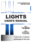
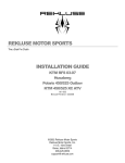
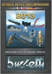
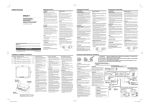
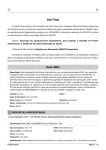
Easy-Mount Dual Sport Kit Installation Manual For Kick-Start Motorcycles Baja Designs • 185 Bosstick Blvd. • San Marcos • CA • 92069 Phone 760.560.2252 • Fax 760.560.0383 www.bajadesigns.com Disclaimer: Warranty: Baja Designs manufactures its own products as well as resells products manufactured by others. Baja Designs makes no express or implied warranties on products not manufactured by Baja Designs including without limitation any warranties or merchantability and fitness for a particular purpose. We will however, pass on all warranties made by the manufacturer, who has the sole responsibility for performing such warranties. Baja Designs will repair or replace any item manufactured by us that we judge to be defective in workmanship or material within 30 days of shipment. We will not be responsible for any indirect or consequential damages in connection with defective merchandise. Products used in racing, competition, or damaged by crash, abuse, or misuse are not warrantable. Indemnification: Buyer hereby acknowledges motorcycle riding is a dangerous sport and that the products and/or supplies purchased from Baja Designs are used in an inherently dangerous activity that may endanger life and limb; and in no event shall the seller, or the seller’s heirs and assigns, be held liable for consequential damages, nor shall seller’s liability on any claim for damages arising out of or connected with the sale, delivery, or use of purchased products and/or supplies exceed the purchase price of the products and/or supplies. Dual-Sport Kit: Installation of a Baja Designs Dual-Sport Kit by itself does not make an off-road motorcycle street legal. Each state has different equipment requirements for street legal motorcycles, including but not limited to such items as DOT approved tires, left and right side mirrors, speedometers, quiet exhaust, chain guards, and side reflectors. Contact your state’s Department of Motor Vehicles or highway patrol for a comprehensive list of equipment that is required for street motorcycles before riding your bike on the street. Street Riding: Riding a motorcycle on the street is very different than off-road riding and requires special skills not learned off-road. Most states require an additional license beyond an automobile drivers license to operate a motorcycle on the street. Make sure to have the proper licensing and skills before riding your bike on the street. Baja Designs recommends contacting the Motorcycle Safety Foundation (800 446 9227) for a rider course near you. Page 2 of 16 Thank you for purchasing the Baja Designs Easy Mount Dual Sport Kit for kickstart motorcycles. This kit will function on almost any non electric-start model as long as the bike is equipped with a lighting coil power source. Installation usually takes about an hour or two. Baja Designs has provided the necessary bikespecific brackets and wire extensions for the popular models it will most likely be used on. See the attached addendum for bike-specific installation instructions. Baja Designs has also provided stator application guides in this manual to help you properly attach your bikes lighting coil to the dual-sport wiring harness. If you have any questions regarding this installation please call Baja Designs at 760.560.2252 or email [email protected]. Please note the following: This kit will not work on bikes with both kick and electric starters (i.e. ’03-on WR’s, KTM 4-strokes, CRF250X’s, etc.) You must use the bike specific dualsport kits for these bikes. This kit will not work on KLX650R’s, DRZ400 kickstart’s, or KLX/DRZ110’s. Don’t even try. ’98-’02 WR’s must use a ’98-’02 YZ rear fender. The default headlight bulb provided in the kit is a 35/35W H4. Depending on your bike’s stator output, it may have the capacity to power a higher wattage bulb than this. Contact Baja Designs for more information. Baja Designs has provided several universal brackets with this kit to be used for rear turn-signal an/or brakeswitch mounting if necessary. These brackets can be purchased separately through Baja Designs. Quick-release feature: The provided wiring harness incorporates quick-release multi-pin connectors that can be utilized to facilitate quick and easy dual sport kit installation and removal. Once the kit is installed, the “dual sport fender” and headlight can be removed with part of the harness permanently attached. A stock fender & number plate (not supplied) can then be installed for off-road or motocross. Page 3 of 16 1. Remove the seat, fuel tank, side panels, and front number plate (or headlight.) 2. Unplug and remove the stock kill button. Take note of the wire(s) that it plugged into. Note that you may leave the stock kill button plugged in if you’d prefer to use it rather than the kill function incorporated into the provided switch panel. 3. Taillight Installation: The shape of the rear fender determines the correct taillight to use. Horizontal (motocross style) fenders with little or no downward curve should use the Baja Designs LED taillight shown in Photo 1. Bikes with curved fenders, such as on older XR’s, should use the Acerbis Dual Sport taillight as shown in Photo 2. If you find that the taillight included with your kit will not fit your fender type, please contact Baja Designs to exchange it for a correct one. Remember that these are universal taillights that sometimes require some modification to allow proper fitment to a particular fender. Shown are the two taillights Baja Designs offers. The dropdown style LED taillight attaches using the four countersunk bolts and bezel washers found in the kit parts bag. The Acerbis Dual Sport taillight attaches using the two 4mm bolts and the 6mm bolt found in the parts bag. Photo 1 Taillight mounting hardware Baja Designs LED Taillight Photo 2 Acerbis Dual Sport Taillight Photo 3 4. Rear Turn Signal Installation: The rear turn signals may attach directly to the fender plastic, the taillight plastic, or to the subframe using the provided brackets. See photos 1,2,&3. If you mount the signals to plastic, drill 3/8” mounting holes. Position the turn Turn signal signals so they cannot contact the muffler brackets and are out of the path of the exhaust flow. NOTE: The polarity of the turn signal wires is only important if you are running LED turn signals. The black wire from the LED signal is ground and will attach with the black from the Baja Designs wiring. The yellow lead from the LED signal will connect to the green or brown (depending on the side) from the Baja Designs wiring. Page 4 of 16 5. Brakelight Switch Installation: Baja Designs has provided both mechanical & hydraulic brakelight switches with this kit. If your bike has a rear drum brake, you must use the mechanical (spring & plunger) style switch. This style of switch is provided with every kit. Refer to the included addendum for bike-specific installation instructions. If your bike is not included in the addendum, see the “Mechanical Brakeswitch” installation section on the next page. If your bike has a rear disc brake, you should use the provided hydraulic brakeswitch. Nissin and Brembo brake systems use two different thread pitches and require two different hydraulic switches. Brembo style switches have only been included in part numbers 12-1300-WT, 12-1300-OG, & 12-1301-WT. Nissin brakes are stock on almost every Japanese bike; Photo 4 European manufacturers mainly use Brembo brakes. The two switches can be identified & differentiated by their thread pitch. The Brembo Hydraulic switch’s threads are finer than those of the brakeswitch Nissin switch. Note that ’90-’99 DR250/350’s have a Nissin brake but must use the Brembo switch. Hydraulic Brakeswitch: Remove the banjo bolt securing the rear brake line to the master cylinder and replace with the hydraulic switch. See Photo 4. Make sure to install the copper Photo 5 crush washers from the stock bolt under the switch. Torque the switch assembly to 25ft-lbs. Bleeding the Brakes: (Do not begin this process unless you have a fresh can of brake fluid.) Remove the lid from the rear brake reservoir. Put the box end of a combination wrench over the brake bleed nipple and install the bleed hose (supplied) tightly over the nipple. Position the loop on the hose above Photo 7 the nipple as shown with the other end Photo 6 of the hose in a container to catch the fluid. Crack the bleed nipple open about 1/8 to a quarter turn keeping the loop in the hose vertical. Slowly depress the brake pedal to fill the hose with fluid. Pump slowly until you have brake fluid extending up into the loop, then you can pump the pedal fairly aggressively to drive air out of the system - The fluid above the bleed nipple will prevent air from re-entering the system. DO NOT LET THE RESERVOIR GO DRY - ADD FLUID AS NEEDED. Pump the pedal until Page 5 of 16 there are no more bubbles, and then close the nipple with the wrench. Double check that the pedal is firm and the brake works properly. Mechanical Brakeswitch: If your bike has a rear drum brake you will need to find a mounting location for the mechanical brakeswitch. Baja Designs has included several brackets in the kit for you to cut, bend, or drill as necessary to mount the switch. When finding a mounting location be sure the switch does not interfere with the throw of the kickstarter or contact your boot while riding. See photos 6 and 7 for examples. Find a suitable location in the brake pedal to drill a small hole and attach the brakeswitch spring. Locate this hole so the brakeswitch plunger cannot pull out to its limit when the pedal is depressed. Depending on the where the brakeswitch gets located you may need to shorten or stretch the spring. We’ll fine-tune its adjustment in step 14. 6. Middle Wiring Harness Installation: Photo 8 Locate the black cable with the white plastic multi-pin connectors at both ends provided with the kit. Position the end with the 8-pin connector so that the connector sits just to the left of the steering head tube. Route the black cable and the orange & white wire pair down along the left side of the frame following the stock wiring harness. The 6pin connector and the orange & white wires should end up at the area on top of the airbox. The 6-pin connector will be attached in the following step. The orange & white wires will be attached in step 11. 7. Rear Wiring Harness Installation and Connections: Locate the rear wiring harness provided with the kit. It has a white plastic 6-pin connector with several sheathed power leads extending from it. Attach the 6-pin connector from the rear wiring harness to its corresponding mate from the middle wiring harness. Attach the 3-pin plastic connector from the rear wiring harness to its corresponding mate from the taillight. Attach the green and black wire pair to the two wires from the right rear turn signal. Polarity is unimportant on incandescent signals. Note: Polarity is important on LED signals so be sure to match the ground with the black wire on the kit. Attach the brown and black wire pair to the two wires from the left rear turn signal. Polarity is unimportant on incandescent signals. Note: Polarity is important on LED signals so be sure to match the ground with the black wire on the kit. Route the red & blue wire pair down to the brake light switch and attach the two leads. Polarity is unimportant. Page 6 of 16 Secure your wiring with zip-ties. 8. Turn Signal Switch Installation: Install the turn signal switch on the left handlebar next to the grip. The switch has two screws that mate the two halves together. Note: Install the two rubber shims provided on the back half of the turn signal switch body. Do not over tighten these screws, as too much force can strip the body of the switch. The clutch perch may have to be moved to the right to make room for the switch. Zip-tie the wires along the bottom of the handlebar (so tie-downs can’t crush them) and over the front of the top triple clamp. 9. Key Switch Installation: Mount the key switch unit off one of your handlebar clamp bolts or upper triple clamp bolts. Make sure it is easy to reach as this will now function as your kill switch for the bike. Make sure the key switch and wires are not contact any part of the chassis. 10. Kill Function Connections: The blue/white and white wire pair from the front harness are the kill leads for the kit. These wires attach to the wire(s) you unplugged your stock kill button from. If your stock kill button only unplugged from one wire, attach the blue/white wire to it and attach the white wire to the chassis of the motorcycle. Most manufacturers use either a black/white or black/yellow wire as the main kill wire. European bikes with SEM or Motoplatt ignitions use orange as the kill wire color. If your stock kill button unplugged from two wires, attach the blue/white wire from the Baja Designs kit into one of these colored wires. Attach the white wire to the remaining wire, which is typically solid black or green. If you are not able to identify or differentiate your kill wires please call Baja Designs for assistance. 11. Front Wiring Connections & Headlight Installation: Attach the black multi-pin connector from the headlight to its corresponding mate from the switch panel assembly. Attach the white multi-pin connector from the headlight to its corresponding mate from the middle wiring harness. Attach the headlight to the fork tubes as shown in Photo 10 using the rubberized clamps. Do not let the metal clamps touch the fork tubes as this can cause a grounding problem on some bikes. Turn the steering from one side to the other to Photo 10 Page 7 of 16 make sure the cable does not bind up or get pulled tight. The brackets are slotted for beam adjustment. Be careful how you route your front brake cable with the new headlight installed. It must remain unrestricted through the full compression of the forks. You may need to remove or relocate your cable guide. Try routing the cable on either side of the headlight brackets to see which way works best. 12. Stator Connections (Please Read Carefully): In this step you will attach your lighting coil (stator) to the kit wiring harness. Find your bike description in the following stator application guide and follow the corresponding instructions. Any additional wires from the stator not addressed in this guide remain attached to their corresponding mates from the stock wiring harness. An asterisk (*) indicates that stator output is marginal. These bikes may require the kit to be run in the “P” (headlight off) switch position in order for the battery to charge. If your bike or stator application does not appear in this guide please call Baja Designs technical support for assistance. The Baja Designs Dual-Sport Kit Photo 11 interfaces with your bike’s stator leads via the orange and white wire pair from the middle wiring harness. Some bikes will require that the orange wire be attached to the chassis of the motorcycle. We have provided an orange extension in the parts bag to allow this (see Photo 11.) If used, the ring terminal must attach to bare metal (paint scraped) to achieve a good connection. The first section of this guide covers bikes that are running aftermarket stator assemblies or add-on lighting coil windings to power the dual-sport kit. Motocross & mini bikes typically fall into this category. The second section covers bikes with factory wound stators in alphabetical order of manufacturer. Full size trail bikes typically fall in to this second category. Aftermarket or add-on lighting coils: Baja Designs or E-line external lighting coils: There will be three wires coming from the stator, two yellows and one red. Tape one of the two yellow wires back (doesn’t matter which) and leave it unplugged. Attach the remaining yellow and red wires from the stator to the orange and white wires from the Baja Designs wiring harness. Polarity is unimportant. The orange extension will not be used. Electrex, Electrosport, or Moose internal add-on lighting coils*: There will be either one or two wires from the stator designated to power lights. If there is only one power wire, attach it to the white wire from the Baja Page 8 of 16 Designs harness. Use the orange ring-terminal extension (shown above) to attach the orange wire from the Baja Designs wiring harness to the chassis of the bike. If there are two power wires from the stator, attach them directly to the white and orange wires from the Baja Designs wiring harness. Polarity is unimportant. If you sent your stator to Baja Designs to be wound with a lighting coil or are using a Baja Designs replacement stator (includes XR & CRF 50/70/ 80/100/150/*250/*450, TTR125, DRZ & KLX125): Attach the two white wires from the stator to the orange and white wires from the Baja Designs wiring harness. Polarity is unimportant. The orange extension will not be used. Factory-wound lighting coils: HONDA *XR200 (’88 & older), *XR250 (’85 & older), *XR350 (all), XR500 (all), XR600 (’85-’90): There will be two wires coming from the stator, one of which is black with a red stripe. This is your ignition wire. Always leave this black/red wire attached to its corresponding mate from the stock wiring harness or the bike will not run. The remaining wire will either be solid blue, white with a blue band, or white with a yellow stripe. This is your lighting coil lead. Attach it to the white wire from the Baja Designs wiring harness. Use the orange extension to attach the orange wire to the chassis of the bike. *XR200 (’89-on), *XR250 (’86-on), *XR400 (all): Attach the pink and yellow wires from the stator to the orange and white wires from the Baja Designs wiring harness. Leave any remaining wires from the stator attached to their corresponding mates from the stock wiring harness. The orange extension will not be used. *XR600 (’91-on), *XR650R (all): Attach the white/yellow & green wires from the stator to the orange and white wires from the Baja Designs wiring harness. You will need to change the terminals to females to make this connection. Polarity is unimportant. Leave any remaining wires from the stator attached to their corresponding mates from the stock wiring harness. The orange extension will not be used. HUSABERG WITH S.E.M. IGNITION Join the two yellow wires from the stator into one terminal. Attach the joined yellow wires from the stator to the white wire from the Baja Designs wiring harness. Attach the blue wire from the stator to orange wire from the Baja Designs wiring harness. Leave the remaining wires from the stator attached to their corresponding mates from the stock wiring harness. The orange extension will not be used. Page 9 of 16 HUSQVARNA On newer Husky’s (2 or 4-stroke) there will be either one or two yellow wires from the stator designated to power lights. If there is only one yellow power wire, attach it to the white wire from the Baja Designs harness. Use the orange ring-terminal extension (shown above) to attach the orange wire from the Baja Designs wiring harness to the chassis of the bike. If there are two yellow wires from the stator leave one of them unplugged and follow the above instruction. KAWASAKI *KDX200/220/250 (all): Attach the yellow wire from the stator to the white wire from the Baja Designs wiring harness. Use the orange extension provided to attach the orange wire to the chassis of the bike. KLX250/300: Attach the two yellow wires from the stator to the white and orange wires from the Baja Designs wiring harness. Polarity is unimportant. KLX650: This kit is not compatible with the KLX650 electrical system. KTM Pre ’97 2-strokes & pre ’00 LC4 4-strokes w/ SEM Ignition: Among the wires from the stator, there will either be two yellows or two yellows and a blue. If there are two yellows with no blue, attach these two yellows to the orange and white wires from the Baja Designs wiring harness. Polarity is unimportant. If there are two yellows and a blue, join the two yellow wires together into one terminal. Attach this terminal to the white wire from the Baja Designs wiring harness. Attach the blue wire from the stator to the orange wire from the Baja Designs wiring harness. *’97-on 2-strokes w/ Kokusan K2 or K3 Stator: If your bike came with the ‘K2” stator, the lighting coil output is only about 45W and the battery will not charge with the headlight turned on. If you have the “K3” stator , the output is about 90W. Attach the yellow wire from the stator to the white wire from the Baja Designs wiring harness. Use the orange extension provided to attach the orange wire to the chassis of the bike. If you have the ‘K3” stator, leave the white wire from the stator unattached to anything. Older KTM’s w/ Motoplatt Ignition: If there are two yellow wires from the stator, attach one of them (doesn’t matter which) to the white wire from the Baja Designs wiring harness. Leave the other yellow wire from the stator unattached to anything. Use the orange extension to attach the orange wire to the chassis of the bike. SUZUKI RMX250: Page 10 of 16 Attach the gray and black/white wires from the stator to the white and orange wires from the Baja Designs wiring harness. Polarity is unimportant. You will have to snip off the plastic connector from the stator wires and install female connectors to make this connection. DR250 & 350: Attach the yellow and black wires from the stator to the white and orange wires from the Baja Designs wiring harness. Polarity is unimportant. You will have to snip off the plastic connector from the stator wires and install female connectors to make this connection. DRZ400 Kickstart: This kit is not compatible with the DRZ400 kickstart electrical system. YAMAHA *WR250 (2-strokes) & ’98-’02 WR250/400/426F (4-strokes) Attach the yellow wire from the stator to the white wire from the Baja Designs wiring harness. Use the provided ground extension to attach the orange wire to the chassis of the bike. *TT500 (all) Attach the pink wire from the stator to the white wire from the Baja Designs wiring harness. Use the provided ground extension to attach the orange wire to the chassis of the bike. *TT350 (all) Attach the yellow wire from the stator to the white wire from the Baja Designs wiring harness. Use the provided ground extension to attach the orange wire to the chassis of the bike. The color of the lighting power wire from the TT350 stator may vary. If you don’t have a yellow wire you’ll need to visually inspect the stator to identify which wire powers the lights (or look in the service manual wiring schematic if you have it.) *TT600: Attach the yellow wire (sometimes has a red stripe) from the stator to the white wire from the Baja Designs wiring harness. Use the provided ground extension to attach the orange wire to the chassis of the bike. IT200 & IT490 At the time of this writing we do not have stator wire color documentation for these bikes. To determine which wire is the lighting power wire you will need to visually inspect your stator (or look in the service manual wiring schematic if you have it.) The wiring installation is now completed. Proceed to the next section to test your work. Page 11 of 16 Key Switch: The Key Switch is used to control both ignition and lighting functions. The key switch must always be in the “Ignition” position indicated by the red dot on the Key Switch for the bike to run or the parking lighting to operate. In the “Ignition” position your running light and taillight should turn on and you should be able to operate your turn signals, headlight and horn. This also allows you to start your bike. System Checkout: The handlebar switch controls the lighting functions only. The lower “dot” position will allow your parking lights to turn on when the key switch is turned on. This position will also allow the use of the turn signals, brakelight, headlight, and horn. The first light position will turn on your low beam and the top light position on the switch will turn on your high beam. When the high beam is selected the top indicator light will illuminate to remind you the high beam is selected. Tip: The NiCad battery can power the headlight without the bike running for a short time. We recommend you take care not to drain your battery and keep the bike running when the headlight is on. Note: The Key Switch must be on for the bike to run or any lighting functions to operate. Ignition/Lighting = OFF Run/Lighting Power = ON High Beam Indicator Headlight High Beam On Headlight Low Beam On Parking Light Position Turn Signal Selector NOTE: Main Power Controlled by Key Switch * Key Switch = Kill Switch for Ignition and Lights Page 12 of 16 Horn Button Wrapping It Up: It is important that all the wires be properly routed and secured. Make sure the wires do not pass over any sharp edges, are pulled overly tight, or can be crushed by the seat, tank, fender, etc. Use all the zip ties provided to securely fasten the wires. Any unwanted movement or chafing means early failure. Make sure all the silicone rubber connector boots and the connectors are pushed firmly together and no bare metal is exposed. Put on the seat, tank, and side panels, go down to your local DMV, and then go roost! Mechanical Brake switch Adjustment: Adjust the mechanical brake switch in its bracket so the brake light comes on near the end of the pedal throw. A brake switch adjusted too sensitive can lead to poor battery charging and premature brake switch failure. Page 13 of 16 TROUBLESHOOTING Nothing Happens When You Turn the Power Switch On. • Fuse is blown. Check for bare wire or terminal shorting against the frame or another wire. • Multi-pin connector not properly connected. • Battery connection poor. Make sure the connectors are fully seated. • Battery is dead. Measure voltage with voltmeter, or connect a 12 volt light across it. The Turn Signals Won't Come On, or Won't Flash • Check turn signal wire connections. Note: On LED Signals polarity is important so make sure the turn signals ground is matched with the black wire on the harness. • Make sure you have connected the correct wires to the turn signals. Check instructions. • Battery voltage is low. If the battery voltage is low, the turn signals won't flash, or will flash very slowly. Running the bike will cure this as well as charge the battery. The Brake Light Won't Come On •. The rear brake system is not properly bled. • Maybe it's on already. Brake and tail connections are reversed. The brake light is already on so there is no increase in light intensity when you activate the brake. Check the red and blue taillight connections. • Connect the two harness leads together at the brake switch. If the brakelight comes on, either the brake switch is defective, or the brake system is not properly bled. Everything Works Except the Headlight • The headlight selector switch must be on low beam or high beam. • Make sure the three prong connector is correctly plugged in and that the wires leading to it are plugged into the harness. • Does the high beam indicator come on when the bike is running and high beam selected? If so, the headlight bulb is burned out or defective. If you still need assistance, call Baja Designs at (760) 560-2252. Battery Care: Your kit contains a 12 volt 0.7 ampere-hour Ni-Cad battery. These batteries are very durable and require no maintenance. There are certain things you can do however to maximize its life. The alternator and voltage regulator in your kit keep your battery fully charged while you are riding, however, when you turn the engine off and the lights are still on the battery is being discharged. With the headlight off, it will take about 30 minutes for the taillight to discharge the battery. With the Ni-Cad battery if you forget and leave the lights Page 14 of 16 on, don’t sweat it. You can deep cycle (drain down and charge back up) a NiCad all you want. If you are doing a lot of slow trail riding where you are on the brakes a lot, and you are running the headlight, the battery may slowly discharge. If you are doing a lot of slow and go riding, select the second headlight switch position (running lights) to charge the battery pack up while you are riding. Riding the bike in the ‘running light” switch position will recharge a drained battery or you can recharge it with a .5 Ah charger for about an hour. A fully charged battery’s voltage reads approximately 14.2 DCV. Maintenance: Occasionally examine the wires in your lighting system to make sure they are not chaffing or binding so that they don't cause you a problem when you're out on the trail or on the road. A well routed, properly secured wiring system is key to getting long life and trouble free performance from your conversion kit. The light bulbs take a beating on a dirt bike, especially the rear taillight’s. The continuous vibration and impact can cause the bulb contact to prematurely oxidize, causing the bulb to fail. Occasionally remove the bulbs (taillight and turn signals) and scrape the soft contact at the base of the bulb and clean its mating contact in the lamp assembly. Page 15 of 16 Baja Designs • 185 Bosstick Blvd. • San Marcos • CA • 92069 Phone 760.560.2252 • Fax 760.560.0383 • [email protected] www.bajadesigns.com Page 16 of 16