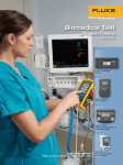
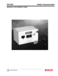
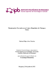
1
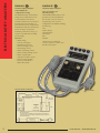
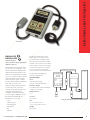
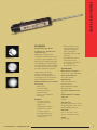
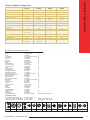
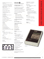
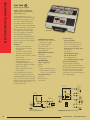
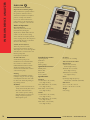
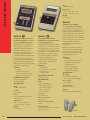
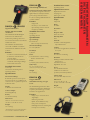
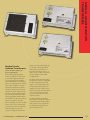
DALE TECHNOLOGY Number one in value. Volume 1 INTERNATIONAL PRODUCT CATALOG ABOUT US I n a small basement in Westchester County, New York, Dale Technology was formed. Dale Technology began in October, 1972, by a young engineer who noticed the medical-device-industry focus on electricalleakage currents. Medical-device manufacturers were required to adhere to stringent guidelines regarding maximum-allowable electrical- leakage currents for their devices. e power cord on most medical devices was a significant contributor to high levels of electrical-leakage currents. Dale Technology responded with the introduction of the Dale Low-Leakage Power Cable. Dale Technology sold over one million feet of this special low-leakage power cable in the first twelve months of business! Dale’s Low-Leakage Power Cable was truly a unique product offering in the medical-device market. At that time, the company was being operated from the basement of a privately owned home in Hartsdale, NY, in Westchester County (hence the company name “Dale”). It all started with a very simple business model: Listen to your customers, give them what they need, and make a modest profit. Over the years, producing low-leakage cable evolved to measuring leakage the Dale Electrical Safety Analyzer was born. e product offering later expanded into Patient Simulators and other devices, such as Medical-Grade Isolation Transformers. Today, Dale Technology is located in Carson City, NV. e Dale Technology product line has expanded considerably and includes test instruments designed to verify the performance and calibration of medical devices. ese devices include defibrillators, external pacemakers, infusion pumps, electrosurgical generators, rigid endoscopes, and even radiology equipment. And YES, Dale Technology still offers its Low-Leakage Power Cable. Our product line and market share have grown considerably, but we have not lost sight of our primary mission: to listen to our customers and provide you with what you need. is is both the legacy and the future of Dale Technology. We will always find new ways to bring you value. NUMBER ONE IN VALUE. current, a natural extension of the business. Resulting from customer demand, Electrical Safety Analyzers DALE601/601E LT544DPLUS/LT544DLITE DALE612S/612SE DALE601CS/601CSE Page 6 Ultrasound Electrical-Leakage Tester DALE800/800 Test Kit Page 7 Endoscope Tester DALE301 Page 8 Patient Simulators DALE14 DALE13 EHS12 EHS10 Page 12 Defibrillator/Pacer Analyzers DALE900 DALE400 Page 14 Electrosurgical Analyzer DALE3000 Page 16 Infusion Device Analyzer DALE4100 Page 17 Intelligent Radiology MAS Meter DALE7000 Page 18 Pressure Meters DALE20 DALE21 DALE22 Page 19 Phototherapy Radiometer DALE30/31 TABLE OF CONTENTS Page 2 Digital Tachometer DALE40 Oxygen Monitor DALE50 Page 20 LIM/GFCI Testers DALE100/100E DALE2000 Page 21 Medical-Grade Isolation Transformers Page 24 Cable and Cord Sets Page 25 Dale Technology Service +1.775.883.3157 • www.daletech.com 1 ELECTRICAL SAFETY ANALYZERS DALE601 DALE601E Solid reliability for comprehensive testing. e DALE601 makes electrical safety testing a breeze. With features such as universal ECG-lead connects, selectable AAMI or IEC test load, and international function labeling, you perform functions more easily with the DALE601 than with other instruments. Besides its simple operation, the DALE601 provides the accuracy you require in a portable and reasonably priced package. Same great features in a 230 VAC package. e DALE601E offers all of the same great features as the DALE601, but in a 230 VAC version. A variety of international power-connector configurations are available, including the following: Electrical Safety Analyzer Measures: • Mains voltage • Current consumption • Earth/chassis resistance • Enclosure-leakage current • Earth-leakage current • Patient-lead-leakage current • Patient-auxiliary-leakage current • Mains on applied part • Transducer-isolation current • External-voltage gradient • Point-to-point resistance • Wall-outlet polarity Electrical Safety Analyzer USA Schuko (Europe) United Kingdom Switzerland Italy Australia Call the factory for additional connector styles for countries other than those listed above. 601/601E probe line drawing DALE601 ��������� ������������� ����������� ���������� ������������ �������� ������������� ��� �������� ������������� ������ ������������������������������������������������������������������������ ������������������� ���������������������������������������������������������������������� ������������������������������������������������������������������������ ���������������������� ������������� ��������������������������� 2 +1.775.883.3157 • www.daletech.com DALE612S LT544DLITE LT544DPLUS DALE612S & 612SE Simple and easy to use. With added features that really “measure up.” Benchmark instruments that extend Dale’s tradition of function and value. Electrical Safety Analyzer e LT544D is a basic electrical safety analyzer that measures both chassis- and earth-leakage currents, as well as chassis resistance. e large display and robust switches make the LT544DLITE easy to operate. A universal power supply allows operation with both 115 V and 230 V devices. Use the LT544DLITE to perform incoming inspections, final inspections, and routine preventive maintenance. LITE Measures: • Earth/chassis resistance • Chassis-leakage current • Earth-leakage current Electrical Safety Analyzer e LT544DPLUS performs the tests found in the LT544 DLITE, with the added capabilities of measuring wall-outlet polarity, line voltage, and instrument current of the test device. It is particularly useful in dialysis clinics, labs, home healthcare organizations, service groups, and for technicians who test and maintain medical devices without ECG leads. e portability, flexibility, and price of the LT544DPLUS make it the ideal companion for technicians who service multiple locations. Measures: • Line voltage • Instrument current • Earth/chassis resistance • Earth-leakage current • Chassis-leakage current • Wall-outlet polarity Electrical Safety Analyzers ELECTRICAL SAFETY ANALYZERS LT544DPLUS e DALE 612S and DALE 612SE bench-model electrical safety analyzers retain the operating features of our portable models, with the capabilities required to test the electrical safety of all types of medical equipment. A built-in ECG simulator provides ten performance waveforms for testing ECG equipment. Normal sinus rhythm, square, sine, and triangle waveforms with adjustable rates are included. Universal connectors allow for the simultaneous connection of ten leads. Measures: • Line voltage • Instrument current • Earth/chassis resistance • Chassis-leakage current • Earth-leakage current • Lead-to-ground current • Lead-to-lead current • Lead-isolation current Waveforms Heart rate: 30, 60, 120, 240 BPM Sine: 10, 50, 100 Hz Square: 0.125, 2.0 Hz Triangle: 2.0 Hz LT544DLITE +1.775.883.3157 • www.daletech.com 3 ELECTRICAL SAFETY ANALYZERS Electrical Safety Analyzers Standard Accessories Chassis cable, coil cord with clamp (8 ft) Operating manual Certificate of Calibration (traceable to the NIST) Soft-sided carrying case Optional Accessories Chassis cable, coil cord with clamp (16 ft) Chassis ground probe, coil cord (8 ft) External-leakage cable, coil cord with clamp (8 ft) External-leakage cable, coil cord with clamp (16 ft) Universal ultrasound probe adapter (for 601 and 601E only) Universal ultrasound probe adapter Chassis cable External-leakage cable Electrical Safety Analyzer Comparison LT544DLITE Display LT544DPLUS LCD 3 1/2 digits DALE601/601E LCD 3 1/2 digits DALE612S/612SE LCD 3 1/2 digits LCD 3 1/2 digits Controls Function switch 2 positions 4 positions 9 positions 9 positions Neutral switch Closed/open Closed/open Closed/open Closed/open Polarity switch Normal/off/reversed Normal/off/reversed Normal/off/reversed Normal/off/reversed Leakage switch Chassis/earth Chassis/earth M.A.P./off/lift ground ISO test/lift ground Lead selector N/A N/A 6 positions 11 positions ECG simulator N/A N/A N/A 10-position waveform selector Measurements Accuracy Resolution Range Accuracy Resolution Range Accuracy Resolution Range Line voltage Accuracy Resolution N/A Range 2% 1V 82 to 265 V 2% 1V 601: 117 V±10% 2% 1V 612S: 117 V±10% Instrument current N/A 5% 10 mA 0 to 19.99 A 5% 10 mA 0 to 19.99 A 5% 10 mA 601E: 230 V±10% 612SE: 230 V±10% 0 to 19.99 A Earth/chassis 1% 10 mΩ 0 to 1.99 Ω 1% 10 mΩ 0 to 1.99 Ω 1% 10 mΩ 0 to 1.99 Ω 1% 10 mΩ 0 to 1.99 Ω resistance 2% 10 mΩ 2 to 19.99 Ω 2% 10 mΩ 2 to 19.99 Ω 3% 10 mΩ 2 to 19.99 Ω 2% 10 mΩ 2 to 19.99 Ω Leakage current 1% 1 µA 0 to 1999 µA 1% 1 µA 0 to 1999 µA 1% 1 µA 0 to 1999 µA 1% 1 µA 0 to 1999 µA Wall-outlet polarity Test load N/A 5 conditions ANSI/AAMI ES1-1993 ANSI/AAMI ES1-1993 85 to 265 VAC, 50/60 Hz 85 to 265 VAC, 50/60 Hz 5 conditions N/A ANSI/AAMI ES1-1993 or IEC601-1 ANSI/AAMI ES1-1993 Power supply Input Rating 15 A for 30 min, 20 A for 2 min 15 A for 30 min, 20 A for 2 min 601: 115 VAC, 50/60 Hz 612S: 115 VAC, 50/60 Hz 601E: 230 VAC, 50/60 Hz 612SE: 230 VAC, 50/60 Hz 15 A for 30 min, 20 A for 2 min 15 A for 30 min, 20 A for 2 min Dimensions (L x W x H) (in) 3.5 x 7.0 x 1.5 3.5 x 7.0 x 1.5 4 x 7.8 x 1.6 8.5 x 11.5 x 4 (cm) 8.9 x 17.8 x 3.8 8.9 x 17.8 x 3.8 10.2 x 19.8 x 4.1 21.6 x 29.2 x 10.2 2 lbs (907 g) 2 lbs (907 g) 3 lbs (1.4 kg) 5 lbs (2.3 kg) Weight 4 +1.775.883.3157 • www.daletech.com ELECTRICAL SAFETY ANALYZERS DALE601CS DALE601CS DALE601CSE Current Sources Meet your IEC testing requirements with these add-ons. e DALE601CS and 601CSE 1-Amp current sources are designed to work hand-in-hand with the DALE601 and 601E Electrical Safety Analyzers. e 601CS comes standard with a 115 VAC U.S. power cord that interfaces directly with the DALE601. e 601CSE has a 230 VAC Schuko power cord that interfaces directly with the DALE601E. ese add-on current sources facilitate testing according to IEC601 requirements, where 1 A current requirements are present for groundcontinuity testing. e 601CS is available only with the standard U.S.-power-plug configuration, while the 601CSE is available with the following power connectors: U.S.A. Schuko (Europe) United Kingdom Switzerland Italy Australia +1.775.883.3157 • www.daletech.com e 601CS and 601CSE work on a simple “push-to-test” basis. Actual ground-resistance readings are taken from the electrical safety tester display. An LED on the current source indicates valid test data or warns of out-of-range measurements. ere are no external power requirements other than the connection to the electrical safety tester. device under test See page 28 for available power connector configurations. Specifications DALE601/601E DALE601CS/601CSE Power Universal power supply (85 VAC – 264 VAC 50/60 Hz) Resistance Range 0 to 3.00 Ω (above 3 Ω an LED flashes to indicate out of range) Output Current 1A Accuracy 1% ± 1 LSD Size 3.5” L x 7.0” W x 1.5” H (9 cm L x 18 cm W x 4 cm H) Using the DALE601CS with the DALE601/601E Weight 2 lbs (907 g) 5 ULTRASOUND ELECTRICAL LEAKAGE TESTER DALE800 Test Kit Leakage Limit to pass: less than 100 µA ±1% DALE800 DALE800 Ultrasound Probe Leakage Tester Test the leakage current of your transesophageal (TEE) ultrasound transducers easily and quickly. e DALE800 tests the electrical safety of ultrasound transducers independent of their ultrasound machines. e test is easy to perform and can be completed quickly. e risk current may be checked between patients during the normal procedure of cleaning the transducer. Unique adapters allow for the testing of many manufacturers’ models of TEE probes. Testing can take place in a cleaning basin. If a transducer is electronically safe for patient use, the green PASS lamp will light. Should a transducer fail the leakage-current test, the red FAIL lamp will light. Verify the electrical safety of your ultrasound transducers by making this probe-leakage test part of your routine disinfecting procedure. Standard Accessories Ultrasound transducer adapters Optional Accessories Conductivity cable Dual conductivity electrode* Ultrasound transducer adapters for: GE YMS/RT GE CGR GE LogicQ HP/Agilent 21369A Transducer* HP/Agilent 21364A, 21365A, 21366A, 213617A Transducers* Siemens/Acuson/Toshiba Hitachi Hard-sided carrying case* * Included in the DALE800 Kit Specifications Power 9 V alkaline battery (approximately 1,000 uses per battery) Conductivity Limit to pass: greater than 133 µA ± 1% Environmental Operating temperature: 15 oC to 40 oC Storage temperature: 15 oC to 65 oC Relative humidity: 90% max Dimensions 6.5” L x 3.8” W x 1.5” H (17 cm L x 10 cm W x 4 cm H) Weight 12 oz (340 g) DALE800 Test Kit Ultrasound TransducerLeakage-Current Test Kit No preparation needed. e DALE800 Test Kit is designed to give users of the most popular HP/Agilent TEE ultrasound probes a “ready-to-test” kit to verify the integrity of their TEE transducers. DALE800 Ultrasound TransducerLeakage-Current Test Kit includes: • DALE800 transducer-leakage-tester • HP/Agilent transducer adapters (2X) • Dual-conductivity electrode • Convenient carrying case DALE800 Ground probe Operating manual DALE800 setup 6 +1.775.883.3157 • www.daletech.com ENDOSCOPE TESTER DALE301 DALE301 Rigid Endoscope Tester Broken lense Dusty lense Foggy lense A simple-to-use, quick check for rigid endoscopes. Finally there is a simple tool for technical and nontechnical personnel to perform a quick evaluation of most rigid endoscopes. With the DALE301, your staff diagnoses problems during incoming inspections, after complaints, pre- and post-service, and as a routine preventive-maintenance inspection. Clinical studies have already documented that by using the DALE301 on incoming inspections of new rigid endoscopes, it will often pay for itself within the first year. With the DALE301, you can identify the following: • Broken lenses • Crooked rod shaft • Normal wear and tear • Internal moisture • Presence of contamination • Lens debris Features • Incoming acceptance inspections performed • Simple to use • Lightweight and compact • No light source or other accessories required • Pre-repair inspections to prevent unneeded repairs and save money +1.775.883.3157 • www.daletech.com • Post-repair inspections to verify a performed service or indicate if a repair was simply a “dusting off” • Compatible with most rigid endoscopes • Compatible with common cameras for hard copy documentation to trend test or to compare and document after service Specifications Outer Diameter of Eyepiece 31.75 mm +0 –0.1 per DIN 58105 End-Cap Inner Diameter No less than 120 mm Optical Design Focal length: 40 mm ± 3% Refraction: 25 dpt Material: PMMA (Plexiglass) Diameter: 19 mm Focal Point Adjustment Scale 16 cm Maximum Diameter of Rigid Endoscope <10 mm Environmental Operating temperature: 15 to 40 oC Storage temperature: -20 to +65 oC Relative humidity: 95% max Dimensions 8.75” L x 1.75” W x 1.75” H (22 cm L x 4 cm W x 4 cm H) Weight 13.1 oz (370 g) 7 PATIENT SIMULATORS Blood Pressure Input/output impedance: 300 Ω Output sensitivity: 5 or 40 μV/V/mmHg Output range: 0 to 300 mmHg Channel-I Manually Selectable Waveforms (mmHg) Arterial: 120/80 Left ventricle: 120/0 Central venous pressure: 15/10 Right ventricle: 25/0 Pulmonary artery: 25/10 Pulmonary artery wedge: 10/2 Atmosphere (0) Static: 20, 40, 80, 100, 200, 250, 300 BPM Artifact BP1/ BP2 DALE14 DALE14 Multiparameter Simulator More comprehensive simulation capability. e DALE14 is powerful enough to test full-function monitors with its onboard ECG, arrhythmia, respiration, blood-pressure and temperature simulations. e DALE14’s pullout card is convenient for looking up all simulations for manual use. Or use its RS232 port for direct connection to a PC. Features • Compact • 12-lead ECG simulation • Wide range of arrhythmias • Auto/manual modes • RS232 port • 2 IBP channels • Respiration • Temperature Standard Accessories Operating manual Battery eliminator Lead-test adapter Carrying case Amplitudes ± 2% lead II or ± 5% Arrhythmias Atrial fibrillation Second-degree heart block type II Right-bundle-branch block Premature atrial contraction Premature ventricular contraction Premature ventricular contraction, early Multifocal PVCs Run of 5 PVCs Bigeminy PVC R-on-T wave Ventricular tachycardia Ventricular fibrillation Pacer Fetal/maternal Autosequence Pulse wave: 4 s/l mV Sine-wave bursts: 10, 40, 50, 60, 100 Hz Triangle wave: 2 Hz Optional Accessories High-Level Output 0.5 V/mV, lead I Specifications Respiration Output configuration: Lead I, II or RL to LL Baseline impedance: 500 Ω or 1000 Ω Delta impedance: 0.1, 0.2, 0.5, 1.0, 3.0 Ω Normal physiological rates: 0, 15, 20, 30, 40, 60, 80, 100, 120 BPM Apnea: 12 and 32 s BP cable Temperature cables RS232 cable Service manual ECG Waveforms Normal sinus rhythm: 30 to 350 BPM Auto mode 8 Performance Waveforms Square: 2 Hz Sine: 10, 40, 50, 100 Hz Triangle: 2 Hz Pulse: 30, 60 BPM Auto mode: 0.5 to 2.0 mV Automated Channel-1 Blood-Pressure Waveform Sequence: Atmosphere (0) Static: 20, 40, 80, 100, 200, 250, 300 BPM Channel-2 Manually Selectable Waveforms (mmHg) Atmosphere (0) Track BPI: duplicates channel 1 select Central venous pressure: 15/10 Swan-Ganz: insert, inflate, deflate, remove Automated Channel-2 Blood-Pressure Waveform Sequence: Atmosphere (0) Static: 20, 40, 80, 100, 200, 250, 300 BPM Temperature 30 °C, 37 °C, 40 °C Power 9 V alkaline battery Dimensions 6.3” L × 4” W × 1.5” H (16 cm L × 10 cm W × 4 cm H) Weight 13.4 oz (380 kg) DALE14 ECG adapter leads +1.775.883.3157 • www.daletech.com PATIENT SIMULATORS DALE13 DALE13 Amplitudes 0.5 to 2.0 mV Fast, complete ECG testing. e DALE13 is a small ECG simulator packed with waveforms designed to verify accuracy of ECG machines, monitors and telemetry units. Features Arrhythmias Atrial fibrillation Second-degree heart block type I Right-bundle-branch block Premature atrial contraction Premature ventricular contraction Run of 5 PVCs Bigeminy PVC R-on-T wave Ventricular tachycardia Ventricular fibrillation Pacer Standard Accessories Autosequence Pulse wave: 4.0 s/l mV Sine wave bursts: 10, 40, 50, 60, 100 Hz Triangle wave: 2 Hz ECG/Arrhythmia Simulator • Simple to-use rotary knob • Handheld • 12-lead ECG simulation • 12 arrhythmias • Universal ECG jacks • Autosequencing of performance waveforms Operating manual Battery eliminator Carrying case Optional Accessories Service manual Specifications ECG Waveforms Normal sinus rhythm: 30 to 240 BPM Performance Waveforms Square: 2 Hz Sine: 10, 40, 50, 60, 100 Hz Triangle: 2 Hz +1.775.883.3157 • www.daletech.com High-Level Output 0.5 V/mV, lead I Power 9 V alkaline battery Dimensions 5.2” L × 3.9” W × 1.4” H (13 cm L × 10 cm W × 4 cm H) Weight 14.2 oz (400 g) 9 PATIENT SIMULATORS EHS10 EHS10 & EHS12 ECG Simulators Performance testing of critical ECG equipment. e EHS10 and EHS12 are compact, battery-operated ECG simulators that are designed to test the operating performance of ECG equipment, including electrocardiographs, patient monitors, and telemetry systems. e EHS10 performs 5-lead ECG simulation, while the EHS12 is capable of full 12-lead ECG simulation. Because they are small and cost-effective, the EHS10 and EHS12 can be included in every technician’s tool kit. Features • 10 ECG-performance-testing waveforms • Small, portable, easy to use • Continuity test of lead wires • Start-up test to indicate proper operation • Low-battery indicator, flashing LED • Fixed-width QRS complex • Crystal frequency source and reference voltage 10 EHS12 • 9 V alkaline battery, 200 hours of operation • Microcomputer-controlled digital information • Universal connectors for lead attachment Specifications Accuracy Amplitude: ± 2% of reading Frequency: ± 0.5% of setting Controls Power switch (2-position toggle) Function switch (10-position rotary) Power 9 V alkaline battery (200 hours of operation) Dimensions EHS10: 4” L x 2.5” W x 1” H (10 cm L x 6 cm W x 3 cm H) EHS12: 6” L x 4” W x 1.5” H (15 cm L x 10 cm W x 4 cm H) Weight EHS10: 4.9 oz (140 g) EHS12: 11.7 oz (330 g) Waveforms Heart rate: 30, 60, 120, 240 BPM Sine: 10, 60, 100 Hz Square: 0.125, 2.0 Hz Triangle: 2.0 Hz Output Impedance Leads 5 KΩ Amplitude (peak-to-peak) Lead I (LA-RA): 1.75 mV Lead II (LL-RA): 2.75 mV Lead III (LL-LA): 1.0 mV Lead C-RL: 5/0 mV +1.775.883.3157 • www.daletech.com PATIENT SIMULATORS Patient Simulator Comparison Display DALE14 DALE13 EHS12 EHS10 YES YES YES NO (5-lead) YES (13) YES (11) NO NO 2-digit LCD 12-lead ECG simulation ECG arrhythmias NO NO NO Pacer simulations YES (1) YES (1) NO NO ECG performance waves YES (9) YES (7) YES (6) YES (6) (50 & 60 Hz) (50 & 60 Hz) (60 Hz only) (60 Hz only) ECG high-level output YES YES YES YES Lead test YES NO YES YES YES (2-ch) NO NO NO Respiration YES NO NO NO Temperature YES NO NO NO Blood pressure w/ autosequence & Swan-Ganz (YSI 700 & 400) Pullout card YES NO NO NO ECG performance autosequence YES YES NO NO Serial port (RS232) YES NO NO NO 9 VDC alkaline battery 9 VDC alkaline battery 9 VDC alkaline battery 9 VDC alkaline battery or eliminator or eliminator Power Blood-pressure and temerature cables ������������ ������� ���� ����������� ����������� ��������� �������� ��������� ����� ������������� ��������������� ��������������� ������ �������������� ������������� ����������������� ������������������ ������������������ ������������������������ �������������� ������������ ��������������������� ���������� ������ �������������� �������� ��������������� ������� ���� ��������� ��������������� ��������������� �������� ������������� �������������������� ����������� ������������� ���������� ������������������������� ����������� ���������� ���������� ������������ ������������� ���������� ������������ ����������� ���������� ���������� ������������ ���������� ������������ ���������������������� ���������� ���������� ���������� ���������� ������������������������� ���������� ���������� ���������� ������������� ����������� ������������ ���������� ���������� ���������� ���������� ���������� ��������������������� ��������� � � � � � � � � � � � � � � � � � � � � � � � � � � � � � � � � � �������������������������� ������������������ ���������������������������� �������������������������������� �������������������������������� ������������������������� ���������������� ���������������� � �������������������������� ������������������������� � � ����� � ������� ������� � ������� +1.775.883.3157 • www.daletech.com � ������� � ������� � ������� � ������� � � ������� ������� � � ������� � ������� � ������� � ������� � � ������� ������� 11 DEFIBRILLATOR/PACER ANALYZERS defibrillation equipment. One cardioversion and 7 emergency scenarios are programmed for EMT-D student training or certification. Attach a serial printer and the DALE900 documents studentresponse times, actual energy discharge levels, cardiac-event listings, and instructor comments. Standard Accessories Internal paddle contact adapters 115 V or 230 V battery eliminator Carrying case Operating manual Optional Accessories Option 1 Disposable electrode adapters Service manual DALE900 Defibrillator Analyzer Output-energy and cardioversion measurement in a compact, batteryoperated package. e DALE900 has the flexibility to test semi- and fully automated defibrillators and is compatible with the wide range of defibrillator technologies utilized in today’s devices equipped with Edmark, Lown, trapezoid, and biphasic-energyoutput waveforms. ese waveforms are provided through the paddles in a 5-lead configuration. To determine the proper synchronization of your defibrillator, the DALE900 measures actual delay time from the peak of the generated R-Wave to the leading edge of the defibrillator-discharge waveform. Features • Energy and cardioversion testing • ECG signal through defibrillator paddles • Slow-motion playback of digitized defibrillator discharge • Preset sequences and ECG simulation with Option 1 12 Specifications DALE900 Optional Features Option 1: Add Option 1 for even-morecomprehensive defibrillator analysis that eliminates errors and cumbersome paperwork. is package offers the following: • User-Programmable Test Sequences: Customize 20 test sequences with programmable protocols and test limits when you add Option 1 to the DALE900. Available tests include cardioversion-maximum-energy verification, and up to 20 energy tests. Sequences for 18 defibrillators are factory preset. • Automated ECG-Performance Testing: Give your DALE900 the ability to output ECG waveforms in a 5-lead configuration. By adding Option 1, you can inspect gain, linearity, and frequency response at the required AHA (American Heart Association) points. A normal-sinus-ECG is sequenced automatically through a series of heart rates to test rate-meter calibration and alarm operation. e output is calibrated at 1.0 mV in Lead 1. • Defibrillator Training: With Option 1, the DALE900 meets the needs of firstresponder training programs that use the latest automatic or semiautomatic Defib Energy Measurement Load Resistance 50 Ω ± 1% noninductive (< 1 mH) High Range Maximum energy: 700 J Accuracy specifications are for energy levels ≤ 360 K Accuracy: ± 2% of reading for 100-360 J; ± 2 J for < 100 J Real-time oscilloscope output: 1 V/1000 V (applied) Low Range Maximum energy: 50 J Accuracy: ± 2% of reading for 20 to 50 J: ± 0.4 J for < 20 J Real-time oscilloscope output: 1 V/200 V (applied) Display Resolution 0.1 J Measurement Time Window 64 ms Real-Time Oscilloscope Output 1000:1 BNC jack Expanded-Time Playback Expansion of 200 to 1 Cardioversion Timing window: -120 to +880 ms at R-wave peak. Waveform: Normal sinus at 60 BPM 1 mV/Lead 1 Normal-Sinus ECG Base Model Selections Cardioversion: 60 BPM V-Fib: Automated defibrillator testing Option-1 Selections Rate accuracy: ± 1% of selection +1.775.883.3157 • www.daletech.com ECG-Performance Testing (with Option 1 only) (Output at 1.0 mV/Lead 1) Square wave: 2 Hz DC pulse waveform: 4.0 s Sine waves: 0.05 to 1000 Hz Triangle wave: 2 Hz Lead-short test: zero output Arrhythmias Atrial fibrillation (fine and coarse) Atrial flutter Sinus arrhythmia First-degree AV Block Second-degree AV Block 1 & 2 ird-degree AV Block Premature ventricular contraction Multifocal PVCs Couplet Bigeminy Trigeminy Run of 5 PVCs Run of 11 PVCs Ventricular rhythm Ventricular tachycardia Ventricular fibrillation 1 & 2 Electro-Mechanical Dissociation (EMD) Asystole Power 9 V alkaline battery or battery eliminator (115 V or 230 V available. Please specify.) Case ABS plastic Dimensions 9” L x 8.25” W x 4” H (23 cm L x 21 cm W x 10 cm H) Weight 5 lbs (2.3 kg) DALE400 Simulated R-, S- & T-Waves Width 5, 10…, 100, 200 ms Testing for an entire range of external pacemakers. Waveforms Square, triangle, haversine, ISO Rate (30 to 120 BPM) External Pacemaker Analyzer e DALE400 has been specifically designed for use with all external cardiac pacemakers including invasive (transvenous) and noninvasive (transcutaneous) types. Its impressive range of tests and simulations will meet the needs of all cardiac units. Features • Handheld portability • All necessary test leads • Large, 2-line LCD display • Comprehensive test ranges • Replaces 5 separate test devices Standard Accessories Test leads Operating manual Pacer Load Adapter (PLA) Optional Accessories Amplitude 0 to 25 mV, in 0.5 mV steps Long-Term Tests Reference value for pulse rate, amplitude and length established from first 10 pulses. ereafter, any deviation over 10% (adjustable) is flagged. Power Four AA cells Current drawn 20 mA approx. or connect to 9 VDC supply Dimensions 7.5” L × 5.5” W × 1.5” H (18 cm L × 13 cm W × 4 cm H) Weight 1.54 lbs (700 g) Carrying case RS232 cable Printer cable Parallel printer AC power supply Service manual DEFIBRILLATOR/PACER ANALYZERS Amplitude: 1.0 mV/Lead 1, ± 5.0% Lead Format AHA (American Heart Association) or European color-coding available Specifications Display 2-line × 16-character LCD Inputs Ventricle pacing signal: (0-12 V, 25 mA), (500 Ω load) Atrial pacing signal: (0-12 V, 25 mA), (500 Ω load) Transthoracic pacing signal: (0-40 V, 250 mA), (50 Ω load) Outputs Parallel printer port Serial computer port Measurement of Pacing Pulse Amplitude: 0 to12 V invasive, 0 to 40 V noninvasive Rate: 30 to 300 BPM Pulse length: (< 1 to 50 ms) DALE400 AV Time Interval 0 to 1000 ms DALE900 electrode adapters 50/60 Hz Interference Signal 0 to 25 mV in 1 mV steps Refractory Period Measurement 20 to 500 ms +1.775.883.3157 • www.daletech.com 13 ELECTROSURGICAL ANALYZER DALE3000 Electrosurgical Analyzer Simple, portable, and digital to satisfy your electrosurgical-unit (ESU) testing needs. e DALE3000 makes it easy to conduct generator-output, HF-leakage, and CQM tests, allowing you to read the results on a bright LED display. Compatible with both isolated and earth-referenced ESUs, the DALE3000 has fifteen standard test loads to match the requirements of most ESUs. All of the high-frequency (HF) leakage tests, as specified in the current IEC and ANSI/AAMI standards, are easily conducted. e DALE3000 will also verify the basic operation of the dispersive electrode’s Contact Quality Monitor (CQM). DALE3000 Standard Accessories Tests Performed Generator Output HF/RF Leakage: Performs tests in accordance with IEC 601- 2-2, 1289-2, ANSI/AAMI HF-18. Earth Referenced Leakage (IEC) Type BF Test 1 Type BF Test 2 Isolated Output Leakage (IEC & ANSI/AAMI) Type CF/Bipolar Test 3 Contact Quality Monitor (CQM) Test leads (4): Active, dispersive, earth reference, CQM Two insulated jumpers Fuses: Two 3.15 A Detachable power-cord set Operating manual Features • Easy-to-use test instrument • Performs output, HF-leakage, & CQM tests • Select watts, current, and test load with a touch of a button • Main test loads from 50 Ω to 750 Ω (in 50 Ω steps) • Performs all IEC & ANSI/ AAMI HF-leakage tests • Auxiliary HF-leakage test load • Large LED, 4-digit numeric display • Oscilloscope output • RS232 serial-port interface for test automation Optional Accessories Serial cables Hard-sided carrying case Service Manual Specifications Measurement Technique A precision, high-voltage/highfrequency capacitive divider samples the applied ESU signal. is voltage and the selected test-load-resistance value are utilized to derive the True RMS current and power values of the applied electrosurgical signal. Modes of Operation Manual Remote Simplex: Transmits data only Duplex: Transmits data and receives control commands Since the instrument’s enclosure is constructed of high-grade plastic, the DALE3000 is lighter than other models. Also, you are protected from potentially dangerous electrical shock while testing the high-voltage, high-frequency ESU-generator output. Displayed Parameters Power (W) RF current (mA) Test load (Ω) DALE3000 ELECTROSURGICAL ANALYZER HF SURGICAL EQUIPMENT ACTIVE 7 HF Load Resistance (200) ����������� ��������� NEUTRAL ������ � SUPPLY MAINS ������������� 5 CQM ��������� ���������������� �������� ������� ������� ����� ��� ����� � ����������� EARTH 1 EARTH Measuring Resistance (200) HF METER M 3 ���������� ���������� ����� � 6 TYPE BF 4 EARTH Contact Quality Monitor Contact Quality Monitor 14 Load from active electrode earth. Load from activetoelectrode to earth +1.775.883.3157 • www.daletech.com Safety Requirements U.S.A.: UL3101-1 Canada: CAN/CSA C22.2 No. 1010-1 1992 International: EN 61010-1 (1990) (73/23 EEC low-voltage directive) Signal Averaging Mode (SAM) 2 rolling average algorithms to smooth ESU output Display 4-digit red LED, seven segments Front-Panel Controls Measurement select (1): Watts or current Load select (2): Increment or decrement Bandwidth (Measurement Circuitry Only) Flat response: 10 kHz to 10 MHz -3dB points: 1 kHz to 20 MHz Electromagnetic Interference and Susceptibility 89/336/EEC Electromagnetic (Amendment 93/68/EEC) EN 50082-1 Group I EN 550221 Class A Top-Panel Input Connections (7) Designations: Generator output-active (1) generator output dispersive (2) earth/ground reference (2) auxiliary HF-leakage load (2) Connector type: 4 mm (.160”) diameter safety sockets (IEC-1010 approved) System Response (Measurement Circuitry and Test Load Sections) -3dB points: 1 kHz to 10 MHz @ 300 Ω Test-Load Section Selections: 15 Range: 50 Ω to 750 Ω Step size: 50 Ω Accuracy: ± 4% of selected value Maximum duty cycle @ 400 W: 50% (period = one minute) Environment Operating temperature: 15 oC to 35 oC Storage temperature: 0 oC to 50 oC Humidity: <90% non-condensing Case High-impact plastic Dimensions 12” L x 13.5” W x 6” H (30 cm L x 34 cm W x 15 cm H) Serial Port Baud rate: 2400 Fixed Connector type: Male DB9 Modes: Simplex and duplex Oscilloscope Output (Uncalibrated) Transformer coupled-output connector type: BNC Auxiliary-Leakage Test Load Fixed: 200 Ω Accuracy: ± 4% rated @ 225 W Input capacitance at 300 Ω Active to neutral: 30 pF Active or neutral to earth ground: 40 pF ELECTROSURGICAL ANALYZER RF Measurements Watts (Resolution) Range: 0.1 to 400 (± 0.1 W) Maximum power input: 400 W Accuracy: ± 5% of reading or ± 3 W (whichever is greater) RF Current (Resolution) Range: 30 to 2500 mA (± 1 mA) Accuracy: ± 2.5% of reading or ± 15 mA (whichever is greater) Weight 12 lbs (5.5 kg) Ventilation (Variable Speed Fan) Over-temperature protection Blocked-rotor optical sensor/detector Power Requirements Operating voltage (frequency): 115/230 VAC (50 Hz/60 Hz) Maximum input: 60 W Fuses: 3.15 A (2) user replaceable (external) Auxiliary Contact-Quality-Monitor (CQM) Test e main test loads are used to perform a simple operational check of the ESU’s CQM feature. �������� ��������������� �������� ����������� ��������� ����������������� � ������ ������������������������ ������� ���������� ����� �������� ��������������� �������� ����������� ��������� � ������� ������ � �� ������ ������ ����� � ��� DALE3000 ELECTROSURGICAL ANALYZER HF SURGICAL EQUIPMENT ACTIVE � ����� �� ����� ��������� ���������� ����� NEUTRAL � SUPPLY MAINS ������ ������� 1 Measuring Resistance (Rated test load) � CQM ��������� ���������� ����� HF METER M �� ����� � ������� ������ ����� � ��� ������ � 2 ����� ����� � � EARTH ������� ����� Load between electrodes Load between electrodes +1.775.883.3157 • www.daletech.com Generator Output Generator output Isolated bipolar output Isolated Bipolar Output 15 INFUSION DEVICE ANALYZER DALE4100 Infusion Device Analyzer Rapid check for infusion pumps. is portable device quickly evaluates the operation of infusion devices with both steady and nonsteady flow patterns. A simple user interface removes the clutter from infusionpump testing. Use the instrument in manual- or computer-control modes. Modes of Operation Flow (Steady Flow) is mode performs direct-flow measurement by timing the displacement of fluid within a known volume. Use this mode for testing devices that have steady flow patterns, such as a syringe driver. e sample size varies with the flow rate, to minimize the time to first reading. Volume (Nonsteady Flow) is mode performs a volume measurement and derives the flow. is sample size is set at 1 ml regardless of the flow rate. Use this mode to test infusion pumps with nonsteady flows and PCAs. Occlusion Pressure Set the infusion pump to the manufacturer’s recommended flow rate, and select occlusion on the DALE4100. Measurements will be displayed in mmHg or psi. is measures the downstream occlusion on the infusion pump. Priming Priming the DALE4100 is a simple technique using an enclosed syringe. Generally this task can be done with less than 5 ml of fluid, depending on the priming solution. Features • Quick, accurate measurements of steady and nonsteady flow devices • Flow-rate, delivered-volume, and occlusion-pressure testing • Portable: attaches on the IV pole • Simple setup and operation • RS232/printer ports 16 DALE4100 Standard Accessories Operating manual Drain tubes Stopcocks Priming syringe Optional Accessories Parallel printer Printer cable RS232 cable Service manual Specifications Flow Rate 1 to 100 ml/hr: ± 4% (normal), ± 2% (high accuracy) 100 to 1000 ml/hr: ± 2% (normal), ± 2% (high accuracy) 1000+ ml/hr: ± 4% (normal), ± 2% (high accuracy) Volume 1 to 100 ml/hr: ± 4% (normal), ± 2% (high accuracy) 100 to 1000 ml/hr: ± 2% (normal), ± 2% (high accuracy) 1000+ ml/hr: ± 4% (normal), ± 2% (high accuracy) Occlusion 0 to 35 psi ± 5% of reading Time to Perform Flow-Rate Measurement 1 ml/hr: 5 min (normal), 60 min (high accuracy) 100 ml/hr: 25 sec (normal), 60 sec (high accuracy) 1000 ml/hr: 5 sec (normal), 5 sec (high accuracy) Power Operating voltage (frequency): 115/230 VAC, switchable (50/60 Hz) Dimensions 6.25” L × 9.75” W × 5.25” H (16 cm L × 25 cm W × 13 cm H) Weight 5 lbs (2.3 kg) +1.775.883.3157 • www.daletech.com INTELLIGENT RADIOLOGY MAS METER DALE7000 Intelligent Radiology MAS Meter A truly unique radiology instrument in a class of its own. e DALE7000 is a unique product for the radiological service technician and engineer. e DALE7000 simultaneously measures MAS, exposure time, and mA while providing mA-waveform information. e DALE7000 displays three 50 ms mA waveform samples so that radiographic and mammographic preheat circuits can be analyzed and adjusted without using an oscilloscope. Based on requests from service engineers, the DALE7000 can be set to include/ exclude the first 10 ms of the mA waveform. e DALE7000 intelligent meter uses a microprocessor to analyze the digital mA waveform and to display accurate values essential for analyzing and calibrating radiographic and mammographic equipment. e meter is designed to analyze any waveform signal, from single-phase (self-halfwave-rectified) waveforms up to and including any of the high-frequency (constant-potential) waveforms. e DALE7000 meter has two sets of mA input jacks for testing both alternating-current (AC) mA signals and direct current (DC) mA signals. e four-line display of the DALE7000 shows the following: Line 1: MAS (average tube current [mA] times mA-waveform exposure time) Line 2: Exposure time (mA waveform exposure time in seconds) Line 3: mA (average tube current [mA] over the entire mA-waveform) Line 4: ree sample mAwaveform values (with no delay) e first waveform value represents the average mA for the first 50 ms of exposure. e second waveform value represents the average mA for the second 50 ms of exposure. e third waveform value represents the average mA for the third 50 ms of exposure. +1.775.883.3157 • www.daletech.com DALE7000 Features • Diagnostic power-up sequence to indicate operational status • Automatic reset • Pushbutton control that causes the meter to include/exclude the first 10 ms of exposure • Automatic LCD update • Automatic power-down when meter is not used for more than five minutes • Display blanks when an exposure is being made • Low-battery indication Reset Automatic reset and LCD update Environmental Operating temperature: 15 to 35 oC Power One 9 V battery (40-hour life) Dimensions 4” L x 6.5” W x 1.3” H (10 cm L x 17 cm W x 3 cm H) Weight 10 oz (280 g) Specifications Dynamic Range 10 to 2,000 mA to 999.9 MAS 1 ms to 6.535 s Accuracy MAS: ± 0.1 MAS or 1% (whichever is greater) mA: ± 1 mA or 0.5% (whichever is greater) Time: ±1 ms or 1% (whichever is greater) 17 PRESSURE METERS Power 9 V alkaline battery Dimensions 5.75” L × 3.125” W × 2.5” H (15 cm L × 8 cm W × 6 cm H) Weight 0.4 oz (295 g) DALE22 Parabolic Flow Adapter DALE20 DALE20 DALE21 Troubleshooting with 1% accuracy for your pneumatic transducers. e DALE20 is a handheld pressuregenerating device, designed for calibration and for troubleshooting pneumatic or hydraulic systems. An LCD indicates pressure received externally or pressures manually generated from the internal chamber. Reliable and accurate measurement of gas or liquid pressures. e DALE21 Universal Pressure Meter measures positive or negative pressures. Use a single mode switch to select one of five ranges. An LCD readout displays pressures received externally from the following sources: ophthalmologic lasers, dialysis machines, automatic tourniquets, drainage devices, IV pumps, diagnostic and surgical suction devices, ventilators, and pressure gauges. Pneumatic Transducer Tester To test blood-pressure transducers or monitors, simply connect a bloodpressure transducer to the luer lock fitting and create any series of pressures from −300 to +300 mmHg. Features • Handheld • Generates and measures positive or negative pressures • Operates with gas or liquid Standard Accessories 3-way stopcock adapter Operating manual Specifications Range −300 to +300 mmHg Accuracy ± 1% of full scale Power One 9 V alkaline battery (60-hour continuous use) Dimensions 5.68” L × 3.5” W × 1.125” H (14 cm L × 9 cm W × 3 cm H) Weight 11 oz (312 g) 18 DALE21 Universal Pressure Meter Features • Handheld use • Air or liquid measurements • External output • Multiple ranges Standard Accessories Operating manual Specifications Range −700 to +800 mmHg −952 to +1088 cm H2O −374 to +428 in of H2O −13.50 to +15.50 psi −13.5 to +100.0 psi Low-cost gas-flow measurement. e DALE22 is a unique, handheld, easy-to-use device enabling users of the DALE21 Universal Pressure Meter to make critical gas-flow measurements in hospitals, factories or service centers. Typical applications include calibrating flows of various gases from wall outlets, breathing machines, ventilators, anesthesia machines, compressors and regulators. Operation of the DALE22 is based on the principle that the differential pressure measured across a known restrictor is proportional to the flow of gas through the restrictor. Features • Handheld • Extremely simple and easy to use • Designed to ANSI, ISO, and ASTM standards • Measures any gas flow • Includes NBS-traceable calibrated flow readings Specifications Flow Range 10 to 250 lpm (2 restrictors: 10 to 75 lpm and 60 to 250 lpm) Flow Accuracy ± 5% of reading Gases Measured Air, O2, N2O, CO2, CO Requires DALE21 Universal Pressure Meter Accuracy ± 1% of full scale Pressure Connector Male luer lock Overpressure Protection 110 psi Voltage Output 1.1 V/psi on all ranges except 100 psi, which is 0.01 V/psi DALE22 +1.775.883.3157 • www.daletech.com Phototherapy Radiometer Instant measurement of light output. e DALE40 is designed to measure light radiation accurately in the blue part of the spectrum from 429 to 473 nm to treat hyperbilirubinemia in newborn children. Features DALE30 DALE30 /DALE31 Digital Tachometers Flexible, dual-function RPM calculations. e DALE30/31 Handheld Digital Tachometers are dual-function instruments providing contact and noncontact measurement of rotational and linear motions. e DALE30 is CE-marked and comes with a calibration certificate with instrument calibration traceable to NIST.* Features • Contact or noncontact measurement • 8-character, constant unit-ofmeasure display • Four memories (last, minimum, maximum, and average readings) • Sixteen units of measure Standard Accessories Convex tip 10 cm, linear measuring wheel Operating manual Specifications Measurement Range Rotational speed 6 to 99,999 rpm in noncontact mode, 6 to 25,000 rpm in contact mode, or equivalent expressed in alternate units Display 8-character dot matrix LCD Contact Adapter Interchangeable tip Battery 9 V transistor battery Dimensions Unit: 7.5” L × 3.75” W × 1.75” H (19 cm L × 6 cm W × 4 cm H) Weight 7.6 oz (220 g) • Large LCD • Accuracy to ± 5% of full scale • Spectral range of 429 to 473 nm • Complete portability Standard Accessories Storage case Operating manual Specifications Spectral Range 429 to 473 nm (max. 97% response at 453 nm) Measurement Range 0 to 1999 μW/cm2 Resolution 1 µW/cm2 Probe Lens matches the cosine-receiving function of human skin Power 9 V battery (150 continuous hours) Dimensions 3.1” L × 1.5” W × 5.7” H (8 cm L × 4 cm W × 15 cm H) Weight 8.8 oz (250 g) DALE50 Oxygen Monitor Watchful monitoring of oxygen levels. e DALE50 Oxygen Monitor offers unmatched performance reliability for respiratory, anesthesiology, neonatal, and home-care applications. Standard Accessories Operating manual Optional Accessories Replacement fuel cell Carrying case Mount (pole or wall) Specifications Display Large LCD Range 0 to 100% Resolution 0.1% Response Time 90% in 12 seconds Warm-up Time None Fuel Cell Ceramatec CAG-25E galvanic disposable fuel cell PHOTOTHERAPY RADIOMETER/ DIGITAL TACHOMETER/ OXYGEN MONITOR DALE40 Cell Life 3 years in most applications, warranted for 2 years Humidity 0 to 95% non-condensing O2 Alarm Flashing red LEDs, 2300 Hz audible alarm beeper Low alarm: 18 to 99% High alarm: 19 to 99% Power Two AA alkaline batteries (3200 hours of continuous operation); low-battery indicator Cable Length 10 ft (3m) when fully extended Dimensions 3.5” L × 5.5” W × 1.5” H (9 cm L × 14 cm W × 4 cm H) Weight 11.2 oz (318 g) DALE50 Features • Large, easy-to-read, custom 31⁄2 digit display • Extra-long sensor life • Quick, in-air calibration setup • Low-power consumption • Self-diagnostic check of analog and microprocessor circuitry * e DALE31 is not CE-marked and does not come with a calibration certificate. DALE40 +1.775.883.3157 • www.daletech.com 19 LIM/GFCI TESTERS DALE2000 LIM/GFCI Tester Accuracy and ease. e DALE2000 is a battery-operated instrument that checks the safety of isolated power systems and groundfault circuit interrupters. is unique device holds the trip reading on its digital display for 10 seconds. Simply plug the DALE2000 into a typical outlet of the system being tested, select the desired test via the pushbuttons, rotate the trip-point selector, and read the test results on the large digital display. Specifications Accuracy Line voltage: ± 2% R, ± 1 LSD Isolation current: ± 1% R, ± 1 LSD LIM trip current: ± 2% R, ± 1 LSD GFI trip current: ± 2% R, ± 1 LSD DALE100 DALE100 & DALE100E Power Line Monitors e DALE100 and 100E Power Line Monitors give you a convenient way to analyze the quality of the power in your facility’s power distribution system. Simply plug the unit into a power outlet and let it monitor what goes on with your AC power. e instrument constantly monitors power-line conditions and events such as: • Hot-line impulses of 20, 50, 100 and 500 V • Neutral line impulses of 1, 5, 10 and 50 V • Surge • High-line voltage • Normal-line voltage • Low-line voltage • Voltage sag • Voltage dropout • Power failure • High-frequency, normalmode noise • Hot and neutral lines reversed • Open ground Flashing LEDs alert you to abnormal conditions and events. e DALE100 is for 115 VAC power systems, while the DALE100E is for 230 VAC power systems. Both units come with USA power connectors. 20 Specifications Voltage Impulses Hot line: 20 V to 500 V Neutral line: 1 V to 50 V Surge 135 V and above RMS line voltage High-line: >125 V Normal-line: 105 V to 125 V Low-line: <105 V Sag: <95 V Dropout: Below 80 V RS for 8 ms Power failure: Below 80 V RMS for 500 ms Resolution Line voltage: 1 V Isolation current: 1 µA LIM trip current: .01 mA GFI trip current: .01 mA Range Line voltage: 85 V to 245 V Isolation current: 0 to 1.999 mA LIM trip current: 1.0 to 7. 5 mA or 2.0 to 14 mA GFI trip current: 1.0 to 11.0 mA or 2.0 to 20 mA Power 9 V alkaline battery (4000 measurements) High Frequency Noise Noise on AC line of 2 V p-p Dimensions 3.5” L x 6.2” W x 1.75” H (9 cm L x 16 cm W x 4 cm H) Frequency 20 kHz to 10 mHz Weight 1.4 lbs (640 g) Hot/Neutral Reverses Outlet is not properly grounded Power 6 ft power cord Dimensions 4” L x 6” W x 1” H (10 cm L x 15 cm W x 3 cm H) Weight 8 oz (230 g) DALE2000 +1.775.883.3157 • www.daletech.com UIT630 MEDICAL-GRADE ISOLATION TRANSFORMERS IT400 IT800 Medical-Grade Isolation Transformers Twelve models to match your power requirements. Dale Technology Medical-Grade Isolation Transformers can help turn any electrical equipment that does not comply with electrical-leakagecurrent standards into a device that is safe for use in the patient-care vicinity. Items such as computers, computer peripherals, CRT monitors, printers, televisions, VCRs and video cameras often have electrical-leakage currents that are beyond acceptable standards for use in the patient vicinity. A Dale Technology Medical-Grade Isolation Transformer can make these products safer to use in patient-care areas. When combining one or more medical devices onto a cart or rack-mounted system, in most cases, the cumulative electrical-leakage current of the “system” no longer meets electrical- +1.775.883.3157 • www.daletech.com leakage-current standards. Again, the use of a Dale Technology MedicalGrade Isolation Transformer can help reduce the danger of micro- or macro-shock, as well as bring system electrical-leakage current within acceptable limits. e Dale UIT630 Universal Isolation Transformer is customer configurable for either 120/240 VAC input and output to accomodate the growing European market that requires CE marking. Access the voltage selector without opening the unit. e UIT630 comes complete with a removable AC power cord and four IEC-type output receptacles. All of Dale Technology’s MedicalGrade Isolation Transformers utilize a toroidal-transformer design, which is vastly superior to the conventional E-I-transformer designs that some other manufacturers use. 21 MEDICAL-GRADE ISOLATION TRANSFORMERS E-I Transformer (found in some other manufacturers’ transformers) Toroidal Transformers Advantages Small Size: Most toroids are smaller than their E-I transformer counterparts. Low Weight: Because they are smaller and more efficient than their E-I laminated-steel counterparts, toroid transformers can be up to 50% lighter, depending on power rating. Low weight simplifies mounting and transport considerations. Low-Stray Magnetic Field: Since a toroid’s primary and secondary windings are uniformly distributed over the entire surface area of the core, undesired electrical noises are suppressed within the toroid. As a result, toroids emit very low radiated magnetic fields. is makes the toroidal transformer ideal for use in areas where highly sensitive electronic devices or circuitry may be in use. Low Mechanical Hum: ere are no laminations or bolts that can loosen over time and generate the audible buzzing noises associated with the common E-I-type of transformers. Low No-Load Losses: Compared to conventional E-I transformers, toroids exhibit extremely low no-load losses. In applications where a circuit is in a “stand-by” mode for a long period of time, the potential cost reduction for power can be as high as 80-90%. 22 Toroidal Transformer (found in all Dale Technology transformers) High Efficiency: Due to its unique construction, a toroidal transformer is typically between 15 and 30% more efficient than a conventional E-I transformer. Low Operating Temperature: Since the toroid core is so efficient, most of the losses in a toroid are in the copper wire. e toroid dissipates heat much quicker than the conventional E-I type, which uses more iron. At half load, a toroid’s temperature rise is only about 30% of what it is at full load. Dale Technology Medical-Grade Isolation Transformers provide years of trouble-free service while enhancing the electrical safety of your facility’s patient-care areas. Features • Toroidal transformers for improved efficiency, reduced size and low weight • Lifetime warranty on toroidal transformer coil • Circuit breakers on IT-series models, fuse on UIT630 • Agency approved (details available on table) • Hospital-grade plugs and receptacles • Low-leakage power cable • OEM-type custom configurations available on large-quantity orders +1.775.883.3157 • www.daletech.com MEDICAL-GRADE ISOLATION TRANSFORMERS IT1100 IT1500-4 IT200 Medical-Grade Isolation Transformers Comparison Specifications AC input (VAC) Max input current (A) AC output (VAC) Max output current (A) IT200 IT400/IT400-4/ IT400-6 IT800/IT800-4/IT800-6 IT1100 IT1500-4/IT1500-6/IT1500-8 UIT630 1.5 @ 120 VAC 3.5 @ 110 VAC 6 @ 110 VAC 8 @ 110 VAC 12 @ 110 VAC 6.3 @ 115 VAC 6 @ 240 VAC 3.15 @ 230 VAC 120 120 120 110 120/240 115/230 1.5 @ 120 VAC 3.5 @ 120 VAC 5.7 @ 120 VAC (UL) 7.6 @ 110 VAC (UL) 11.5 @ 120 VAC (UL) 6.25 @ 120 VAC 6.5 @ 120 VAC (CSA) 7 @ 120 VAC (CSA) 12 @ 120 VAC (CSA) 3.12 @ 240 VAC 120 110 (rated) 110 110 110/240 115/230 6 @ 240 VAC (UL) Max output power (VA) (rated) 180 420 684 (UL) 836 (UL) 1380 @ 120 VAC UL) 750 @ 120 VAC 780 (CSA) 840 (CSA) 1440 @ 120 VAC (CSA) 749 @ 240 VAC 1440 @ 240 VAC (CSA) Leakage current (µA) <50 <50 <50 <50 <50 <50 50/60 50/60 50/60 50/60 50/60 50/60 Load regulation (%) 5 5 5 5 5 5 Voltage isolation KV 4 4 4 4 4 4 Frequency (Hz) (toroid primary to secondary) Weight (lbs) Transformer type Power-cord length/gauge 10 12 18 22 30 18 Toroidal Toroidal Toroidal Toroidal Toroidal Toroidal 8 ft / 18 AWG 8 ft / 18 AWG 8 ft / 18 AWG 8 ft / 18 AWG 12 ft / 14 AWG 10 ft detachable 18 AWG (#181000 cord set) Surge suppression & EMI/RFI filtering Optional Optional Optional Optional Optional Optional Medical-grade receptacle(s) 1 duplex IT400 ± 1 duplex IT800 ± 1 duplex 1 duplex IT1500-4 - 2 duplex 4 IEC-type Size (in) 5.4 x 4.3 x 4.3 LxWxH Agency certifications CSA IT400-4 ± 2 duplex IT800-4 ± 2 duplex IT400-6 ± 3 duplex IT800-6 ± 3 duplex IT400 ± 8 x 5.5 x 3.6 IT800 - 9.5 x 6.9 x 3.6 IT400-4 - 9.5 x 5.5 x 3.6 IT800-4 - 11.3 x 6.9 x 3.8 IT400-6 - 9.5 x 5.5 x 3.6 IT800-6 - 11.3 x 6.9 x 3.8 UL 2601.1 / CSA UL 2601.1 / CSA IT1500-6 ± 3 duplex IT1500-8 ± 4 duplex 10.0 x 7.0 x 5.0 UL 2601.1 / CSA All - 12.5 x 8.6 x 5.3 10.7 x 8 x 5.3 UL 2601.1 / CSA CE (EN 60601-1) CE (EN 60601-1) Chassis material/ finish Aluminum / Clear Iridite * Specifications subject to change without notice. +1.775.883.3157 • www.daletech.com 23 CABLE AND CORD SETS DALE Cable & Cord Sets Replacement power cords and components. A wide variety of hospital-grade rewireable and molded power-cord sets, hospital-grade plugs, and power connectors are available for all medical and dental equipment applications. ese cords and connectors meet all applicable UL standards. Power cords are available with either standard power cable or Dale Technology’s exclusive Low-Leakage Power Cable. See the current Dale Technology price list for a full listing of these cord sets and connectors. USA 15A/125V EURO-SCHUKO 16A/250V SWISS 10A/250V Low-Leakage Power Cable. Dale Technology’s Low-Leakage Power Cable is the safest means of supplying electrical power to medical equipment. e unique construction properties allow for less than 1 µA per foot of electrical-leakage current. e outer jacket material is rugged PVC. ese special features combine to make Dale Technology’s Low-Leakage Power Cable the best choice for all power and extension cords used in medical applications. Available in 18/3 SJT, 16/3 SJT, 16/3 ST and 14/3 SJT sizes. USA and international wiring color-coded cable is available. See the current Dale Technology price list for a full listing of Low-Leakage Power Cords. Available for purchase by the foot. AUSTRALIAN 10A/250V ITALIAN 10A/250V UK 13A/250V USA 20A/250V Cord end connectors Cross-sectional view of Low-Leakage Power Cable 24 +1.775.883.3157 • www.daletech.com S Technical Service Center When you require assistance with our products, call our Technical Assistance Center. Your call will be handled by a factory-trained Customer Service Engineer. You can also contact us for assistance by fax, e-mail, or letter. Calibration and repair are provided by our factory-operated Service Center in the U.S. or factory-authorized service centers around the world. New Service Policies Instrument Evaluation Charge • $75 to evaluate a unit, which is applied to the repair cost DALE TECHNOLOGY SERVICE SERVICE Dale Technology Service if repair is approved by customer Expedited Service • 50% premium charged for one-day calibration turnaround when approved by Service Coordinator Labor Rate • $115/hr for time-and-materials work Service Pricing • • Flat rate for calibration and very minor repair Time and material for all repairs • Actual return-shipping pricing for service units, plus a handling fee for packaging and handling costs Return Shipping Repair Warranty • • Ninety days on parts and labor for work performed on units serviced One year material and workmanship on new units Data Fees • • Calibration certificate included in calibration fee Pricing for calibration and pre-calibration data available from factory. RMA Requirement • RMAs (Return Material Authorizations) not required to send units to Dale Technology +1.775.883.3157 • www.daletech.com 25 DALE TECHNOLOGY Dale Technology • 5200 Convair Drive Carson City, NV 89706 • Tel: +1.775.883.3157 • Fax: +1.775.883.6782 Service Fax: +1.775.886.6320 • Email: [email protected] • www.daletech.com