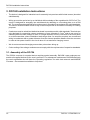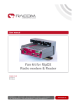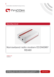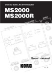
1
Service manual for DC/DC converter
.
DCC24
.
version 1.2
9/15/2015
RACOM s.r.o. • Mirova 1283 • 592 31 Nove Mesto na Morave • Czech Republic
Tel.: +420 565 659 511 • Fax: +420 565 659 512 • E-mail: [email protected]
www.racom.eu
Table of Contents
1. DC/DC converter ............................................................................................................................. 5
1.1. Brief description .................................................................................................................... 5
1.2. Application ............................................................................................................................ 5
1.3. External circuitry ................................................................................................................... 6
1.4. Technical parameters of the DCC 24 ................................................................................... 6
1.5. Product Consistency ............................................................................................................ 6
2. Declarations .................................................................................................................................... 7
2.1. Declaration of Conformity ..................................................................................................... 7
2.2. Country of Origin .................................................................................................................. 9
3. DCC24 Installation Instructions ..................................................................................................... 10
3.1. Assembly of the DCC24 ..................................................................................................... 10
4. Warranty and Servicing ................................................................................................................. 11
5. Conditions for DCC24 ................................................................................................................... 12
5.1. Important Warning .............................................................................................................. 12
5.2. Conditions of Liability for Defects and Instructions for Safe Operation of Equipment ........ 12
© RACOM s.r.o. – DCC24
3
4
DC/DC converter
1. DC/DC converter
1.1. Brief description
•
The DCC 24 is a switched step-down converter, which converts DC voltage in the range 20 V to
60 V on the input side to 13.8 V / 2.5 A DC on the output side.
•
The converter has high efficiency, typically better than 80 %.
•
It is resistant to polarity reversal of the input voltage, undervoltage at the input, shorting at the output
and connecting voltage to the output terminals. If the input voltage descents under 16.5 V (at Iout
= 2,5 A) then the converter switched off to prevent the unstable conditions.
•
Assembly on to DIN rail TS35.
•
Minimum ground plan dimension: 35 × 75 mm.
•
Maximum demand charge: 35 W.
1.2. Application
•
The DCC24 converter is suitable for DC voltage supply to electrical devices when it is necessary
to convert DC voltages in the 20 V to 60 V range to 13.8 V DC and with a maximum output current
of 2.5 A.
•
It is typically used for supplying MORSE system devices (MR25 and MR400 radio modems) media
where the backed up distribution is 24 V DC (or 48 V DC).
•
Due to its high efficiency and small dimensions the DCC24 converter finds use in supplying electronic equipment located in mobile devices with a 24 V DC on-board network.
•
The design and construction of this device allows for long-term loading and for this reason it is
primarily determined for continuously running applications.
© RACOM s.r.o. – DCC24
5
DC/DC converter
•
DC/DC converter is designated for Assembly on to DIN rail TS35, ground plan dimension is 35 ×
75 mm.
1.3. External circuitry
Connections of input and output wires to terminals of the converter are shown in the following diagram:
Terminals are of ENTRELEC type and enable connection of conductors with maximum cross section
2
of 2,5 mm .
1.4. Technical parameters of the DCC 24
Rated input voltage (DC)
24 V
Rated input current
1.5 A
Recommended range of input voltages (DC)
19 V – 60 V
Maximum range of input voltages (DC)
16,88 V – 60 V
Output voltage
13.8 V
Max. output voltage deviation
max. ±3 % at 19–60 V,
max. ±6,5 % at 16,8–19 V
Maximum output current
2.5 A
MTBF (mean time between failures)
> 100 000 hours
Operating range of temperature
-25 to +55 °C
Relative humidity
10–90 %
Dimensions: length × width × height
35 × 75 × 100 mm
Note
For converters manufactured before February 2008, is the input voltage in the range of
20–60 V.
1.5. Product Consistency
Railway Safety Appliance Standards Regulations
nd
Electronic appliances in railway vehicles
CSN EN 50155 ed. 2 : 2002. art. 10.2.8.2
CSN EN 50121 art. 7: tab. 3 and 4
EMC (Electromagnetic Compatibility)
CSN EN 50121-3-2 art. 8
Vibrations and beats
CSN EN 61373
RACOM s. r. o. hereby declares that its GPRS modem MG100 complies of the European Uniondirectives
89/336/EEC. This equipment therefore bears the CE marking.
6
DCC24 – © RACOM s.r.o.
Declarations
2. Declarations
2.1. Declaration of Conformity
© RACOM s.r.o. – DCC24
7
Declarations
Fig. 2.1: Declaration of conformity
8
DCC24 – © RACOM s.r.o.
Declarations
2.2. Country of Origin
Country of Origin Declaration
Producer:
RACOM s.r.o.
Address:
Mirova 1283, 592 31 Nove Mesto na Morave, Czech Republic
VAT No:
CZ46343423
We, the manufacturer, hereby declare that Country of Origin of the RAy microwave links
and its accessories is the Czech Republic, EU.
Part Number
MS2000/12
MS2000/24
MSU120
DCC24
Description
230 V AC / 13.8 V DC, intelligent back-up
230 V AC / 24 V DC, intelligent back -up
Arbitrary solar panel / 14.7 V DC
20-60 V DC / 13.8 V DC
Nove Mesto na Morave, 1 of March 2014
Jiri Hruska, CEO
RACOM s.r.o. • Mirova 1283 • 592 31 Nove Mesto na Morave • Czech Republic
Tel.: +420 565 659 511 • Fax: +420 565 659 512 • E-mail: [email protected]
www.racom.eu
Fig. 2.2: Country of Origin declaration for MS2000
© RACOM s.r.o. – DCC24
9
DCC24 Installation Instructions
3. DCC24 Installation Instructions
•
The device is designed for industrial use for assembly into premises with limited access (electrical
switchboards).
•
Wiring up must be carried out by an individual with knowledge of the regulation No. 50/78 Coll. The
source is designed for assembly into switchboards by attaching to a mounting plate on to a DIN
rail. The mounting plate and DIN rail must be properly grounded in accordance with valid standards.
The source must be located in such a way so as not to prevent air circulation necessary for cooling
purposes.
•
Conductors must be wired into labelled terminals in accordance with valid standards. Terminals are
2
only designed for connecting copper conductors of max. diameter 2.5 mm and do not serve for
switching devices under voltage. If there is a larger distance from the converter to the solar panel
or to the accumulator, where installation leads longer than 3 m would be required, we recommend
wiring in conductors with a greater diameter from the shortest possible distance from the converter
in order to limit power losses in the circuit when it is at maximum charging current.
•
We do not recommend changing accumulator poles when wiring up.
•
Colour coding of low voltage conductors must comply with the requirements of respective standards.
3.1. Assembly of the DCC24
The DCC24 converter is a special device requiring special assembly. RACOM´s own employees assemble all supplied devices at the user's premises. For subsequent maintenance RACOM shall train
the user's specialists who will have the Operating regulations for radio data networks and MORSE
Firmware - Documentation available to help them.
10
DCC24 – © RACOM s.r.o.
Warranty and Servicing
4. Warranty and Servicing
The manufacturer assumes liability for defects for a period of 24 months. Only the manufacturer, RACOM
s.r.o. Mírová 1283, 592 31 Nové Město na Moravě, Czech Republic, Tel.: +420 566 618 578, is entitled
to repair any devices.
© RACOM s.r.o. – DCC24
11
Conditions for DCC24
5. Conditions for DCC24
5.1. Important Warning
RACOM s. r. o. (hereinafter referred to as RACOM) is the exclusive owner of all rights to this operator
manual. All rights reserved. Any duplication of this manual in any way, shape or form, or translation to
any other language (without the prior written consent of the owner of the rights) is strictly forbidden.
RACOM retains the right to make changes to the technical specification or functions of this product or
to terminate production of this product, or to terminate service support of this product without advance
written notice to the customer. RACOM firmware is available free of charge. Source code is the property
of RACOM and is not available to any user. Any commercial use of the software with this licence is
strictly forbidden. Changes to software and documentation are forbidden. RACOM firmware is released
with the intention that it will be useful, however without any specific guarantees.
Under no circumstances is the Racom or any other company or person responsible for incidental, accidental or related damage arising as a result of the use of this product. The manufacturer shall not
provide the user with any form of guarantee containing assurance of the suitability and applicability for
its application. RACOM products are not developed, designed or tested for use in equipment which
directly affects the health and life functions of humans or animals and neither as part of other important
equipment, and RACOM does not provide a guarantee if company products are used in such equipment.
5.2. Conditions of Liability for Defects and Instructions for Safe Operation
of Equipment
Please read these safety instructions carefully before using the product:
•
Liability for defects does not apply to any product that has been used in a manner which conflicts
with the instructions contained in this operator manual, or if the case in which the converter is located
has been opened, or if the equipment has been tampered with.
•
Equipment mentioned in this operator manual may only be used in accordance with instructions
contained in this manual. Error-free and safe operation of this equipment is only guaranteed if this
equipment is transported, stored, operated and controlled in the proper manner. The same applies
to equipment maintenance.
•
In order to prevent damage to the converter and other terminal equipment the supply must always
be disconnected upon connecting or disconnecting the cable to the radio modem data interface. It
is necessary to ensure that connected equipment has been grounded to the same potential. Before
connecting the supply cable the output source voltage should be disconnected.
•
Only undermentioned manufacturer is entitled to repair any devices.
12
DCC24 – © RACOM s.r.o.
Conditions for DCC24
Tab. 5.1: RAy10 Radio parameters
RAy10
Channel spacing 7 MHz; limits for ACCP/CCDP
Raw
User
Modulation Bit Rate Bit Rate
[-]
[Mbps]
RSS / SNR for
-6
BER 10
Co-channel
rejection*
Adjacent
channel
Selectivity*
Blocking
1 dB
1 dB
± 17.5 MHz
RSS
SNR
declared / limit declared / limit declared / limit
[dBm]
[dB]
[dB]
[dB]
[dB]
QPSK
12 /H
8,5
-96
7,5
-11 / -23
17 / 0
30 / 20
QPSK
12 /L
9,9
-93
8,5
-14 / -23
15 / 0
31 / 20
16 QAM
24 /H
17,3
-88
13,5
-17 / -30
14 / 3
24 / 20
16 QAM
24 /L
19,4
-87
14,5
-19 / -30
14 / 3
23 / 20
32 QAM
30 /H
22,3
-83
17,5
-22 / -33
12 / 2
22 / 20
32 QAM
30 /L
24,6
-82
18,5
-24 / -33
11 / 2
20 / 20
64 QAM
36 /H
28,3
-80
20,0
-24 / -33
11 / 2
20 / 20
64 QAM
36 /L
28,8
-79
20,5
-25 / -33
10 / 2
20 / 20
* Guaranteed values and according limits for specifications of disturbance attenuation are shown for
lucidity in the same form as the parameter of Blocking. It is therefore a ratio of I / C (signal disturbance
output / useful signal output), expressed in logarithmic units.
Tab. 5.2: RAy10 Radio parameters
RAy10
Channel spacing 7 MHz; limits for ACCP/CCDP
Raw
User
Modulation Bit Rate Bit Rate
[-]
[Mbps]
RSS / SNR for
-6
BER 10
Co-channel
rejection*
Adjacent
channel
Selectivity*
Blocking
1 dB
1 dB
± 17.5 MHz
RSS
SNR
declared / limit declared / limit declared / limit
[dBm]
[dB]
[dB]
[dB]
[dB]
QPSK
12 /H
8,5
-96
7,5
-11 / -23
17 / 0
30 / 20
QPSK
12 /L
9,9
-93
8,5
-14 / -23
15 / 0
31 / 20
16 QAM
24 /H
17,3
-88
13,5
-17 / -30
14 / 3
24 / 20
16 QAM
24 /L
19,4
-87
14,5
-19 / -30
14 / 3
23 / 20
32 QAM
30 /H
22,3
-83
17,5
-22 / -33
12 / 2
22 / 20
32 QAM
30 /L
24,6
-82
18,5
-24 / -33
11 / 2
20 / 20
64 QAM
36 /H
28,3
-80
20,0
-24 / -33
11 / 2
20 / 20
64 QAM
36 /L
28,8
-79
20,5
-25 / -33
10 / 2
20 / 20
* Guaranteed values and according limits for specifications of disturbance attenuation are shown for
lucidity in the same form as the parameter of Blocking. It is therefore a ratio of I / C (signal disturbance
output / useful signal output), expressed in logarithmic units.
© RACOM s.r.o. – DCC24
13