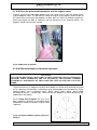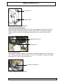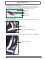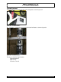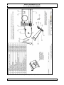
1
©
AirBorne WindSports Pty. Ltd.
XT 912 Maintenance Manual
XT 912 Light Sport and Primary Category
Aircraft
MAINTENANCE MANUAL
ISSUE 2.0
Manufacturer:
Phone :
Fax :
Website :
AirBorne WindSports Pty Ltd
Unit 22/30 Kalaroo Rd
Redhead, NSW 2290
Australia
+ 61 2 4944 9199
+ 61 2 4944 9395
http://www.airborne.com.au/
Part # 108346
Issue 2.0
May 2007
Page 1
©
AirBorne WindSports Pty. Ltd.
XT 912 Maintenance Manual
DATA PACKAGE
This manual constitutes one part of the complete data package that accompanies the aircraft.
Following is a list of each of the components which are required.
• Pilot’s Operator’s Handbook or Aircraft Operating
Handbook
• XT 912 Maintenance Manual
+
• XT 912 Illustrated Parts Catalogue
• Wing Maintenance Manual
• Wing Illustrated Parts Catalogue
• Rotax Owners Manual
• Rotax Maintenance (Compact Disk)
•
Radio Manual – If Installed
•
BRS Parachute Manual – If Installed
•
Transponder Manual – If Installed
Table 1 XT 912 Data Package
Issue 2.0
May 2007
Page 2
©
AirBorne WindSports Pty. Ltd.
XT 912 Maintenance Manual
REVISION HISTORY
January 2007- combined Primary Category Maintenance manual with LSA maintenance skills
requirements. Insert LSA maintenance privileges section. Introduction of the XT Outback,
rubber cushion front end suspension maintenance schedule and description added.
May 2007- Addition of hydraulic brake. Addition of Warp Drive propeller and pitch
setting/measurement methodology. Minor changes to formatting are made throughout.
AMENDMENT RECORD SHEET
Amendment
Date
Affected
Sections
Affected Pages
Date Inserted
Signature
Table 2 Amendment Record Sheet
NOTE
Airbornes data packages will be revised from time to time. Owners registered on AirBorne’s
database will be notified of any changes to data and directed to the AirBorne website
(<http://www.airborne.com.au/>) for the applicable pages. The amended pages should be
printed and the prior page replaced in the folder as soon as possible. The amendment table
should at that time be updated with the appropriate details and date. Revised pages will be sent
by mail if requested.
Issue 2.0
May 2007
Page 3
©
AirBorne WindSports Pty. Ltd.
XT 912 Maintenance Manual
LOG OF ALL EFFECTIVE PAGES
Page
Issue
Date
All of issue
2.0
May2007
Page
Issue
Date
Table 3 Log Of All Effective Pages
Issue 2.0
May 2007
Page 4
©
AirBorne WindSports Pty. Ltd.
XT 912 Maintenance Manual
INTRODUCTION
This manual contains factory recommended procedures and instructions for ground handling,
servicing and maintaining the XT 912 Base section of this aircraft. The procedures described are
to be used in conjunction with the National Airworthiness Authority (NAA) of the country of
registration. Any NAA maintenance requirement takes precedence over this manual.
This manual will be used in conjunction with a certified wing, and therefore the operator is
directed to reference the wing maintenance manual for any issues that are related to the wing
component of the aircraft.
Skills
Only people with an adequate skill level should perform maintenance on this aircraft. A sound
understanding of mechanical systems, and good experience with the necessary tools and
procedures is required - as the continuing airworthiness of the aircraft relies on the competence
of the person performing the maintenance. Assessment and judgement of the condition of each
individual component is required, which necessitates a sound understanding of the purpose of
each component in the system. All maintenance and repairs must be carried out in accordance
with good aeronautical practices.
Skills and authorisations specific to Special Light Sport Aircraft
Maintenance tasks are rated in the categories listed below, according to the applicable category
of registration and skill levels required to perform those tasks:
Owner— FAA regulations authorize SLSA aircraft owners who hold at least a sport pilot
certificate to perform maintenance as outlined in 14 CFR Part 43. To perform
inspections on aircraft condition, functional checks and maintenance in between
inspections carried out by LSA Repairman Maintenance certificate holders.
LSA Repairman Maintenance— This certification authorizes a certificate holder to
perform line maintenance, repairs and alterations to S-LSA as the task allows. Includes
100 hourly and yearly inspections on S-LSA.
A&P—Mechanic Certificate with Airframe and or Powerplant rating. To perform heavy
Maintenance on airframes or powerplant as the rating allows.
Task Specific—Applicable to the following ratings:
LSA Repairman Maintenance with appropriate task specific training or;
A Mechanic Certificate with appropriate task specific training.
Authorizes the holder of mechanic certificate or a repairman certificate who has
received task specific training, to perform the tasks approved under that training.
Allows a repairman certificate holder to perform heavy maintenance, repairs and
alterations on the SLSA.
E.g. The Mechanic Certificate holder may obtain Task Specific training on Rotax
engines, to allow overhaul etc.
Issue 2.0
May 2007
Page 5
©
AirBorne WindSports Pty. Ltd.
XT 912 Maintenance Manual
Skills and authorisations specific to Experimental Special Light Sport Aircraft
LSA Repairman Inspection— To perform line maintenance and inspections to be completed on
an E-LSA by a responsible owner, who holds an FAA repairman certificate (light sport aircraft),
with an inspection rating or equivalent.
There are no requirements for minimum certification to perform any other task on an
experimental aircraft. However, Airborne recommend that only people with an adequate skill
level should perform maintenance on this aircraft as described at the start of this section.
Other Categories of Registration
This aircraft is certified as a Primary Category aircraft and when supplied with this manual and
Special Light Sport placards is a Light Sport eligible aircraft. This manual is created to be
compliant to the standards applicable to Special Light Sport Aircraft. Skill levels required to
perform tasks are applicable to Special Light Sport registered aircraft.
The category of registration may be quite varied; as such the maintenance requirements of this
aircraft are to be applied in conjunction with the requirements of the National Airworthiness
Authority (NAA) of the country of registration. Any NAA maintenance requirement takes
precedence over this manual.
In some countries the owner is permitted to perform maintenance on their own aircraft. If there
are any doubts regarding the required and appropriate maintenance then the safety of the
aircraft may be jeopardised in continuing with self maintenance. In this situation an Airborne
Dealer should be contacted for the correct procedures and or servicing.
Tooling
There are no specialised tools (except for the air shocks) needed for the maintenance described
in this manual, following is a list of the type of tools that may be required. NB. Loctite will be
required in certain locations and should always be replaced after disassembly.
•
•
•
•
•
Loctite (243, 567 and Antisieze Lubricant # 76764) for the frame section.
The Rotax Maintenance Manual gives a list of consumable materials in section 2.5.
Ring / Open ended Imperial Spanner set
Ring / Open ended Metric Spanner set
Torque wrench
WARNING
SPECIALISED PUMPS MUST BE USED FOR THE AIR SHOCKS – PRESSURES UP TO 600
PSI EXIST.
•
•
•
•
•
•
•
•
Air Pump (Schrader Style Valve)
Various petroleum lubricants
Dry Lubricant – lubricant which doesn’t attract dust after application
Tie wire, and tooling
Wire and Swages and tooling
Hex key set (metric and imperial)
Petrol resistant thread sealant tape
Various general care items
This list may not be comprehensive.
Issue 2.0
May 2007
Page 6
©
AirBorne WindSports Pty. Ltd.
XT 912 Maintenance Manual
Service Difficulty Reporting
Any service difficulties or defects should be reported to Airborne using the form contained in
appendix A.
WARNING
REPAIRS SHOULD NOT BE CONDUCTED UPON THE FOLLOWING ITEMS AS THEIR
STRUCTURAL INTEGRITY IS CRITICAL TO SAFETY.
THE MAST STRUCTURES, HANG POINT, BASE BEAM, FRONT FORK ATTACHMENT
ASSEMBLY, LANDING GEAR STRUTS.
OTHER MINOR REPAIRS CAN BE CARRIED OUT IN ACCORDANCE WITH FAA AC 43.13
1B
Format
The manual has been prepared using the ATA format, which provides a standard layout of the
chapters to be included, and their content. Some of the chapters are not included as they are
deemed to be not applicable to this aircraft. The content is compliant with the Light Sport
Aircraft standard. Skill levels required to perform tasks are applicable to the levels of
qualification issued under the Light Sport Aircraft System.
The information in this manual is based on the data that was available at the time of its
publication. The latest amendments to this manual will be issued on the Airborne website in PDF
format. This should be printed out and added to the manual. Therefore it is important that
operators keep a regular check on the website for any amendments that have been made. If any
errors or omissions are found in this manual please advise the factory.
WARNING
THE INFORMATION IN THIS MANUAL NEEDS TO BE FOLLOWED, AND IT IS NOT
ACCEPTABLE TO MAKE CHANGES TO THE MATERIALS AND OR PHYSICAL FEATURES
OF THIS AIRCRAFT. IN PARTICULAR THE GRADES OF BOLTS THAT HAVE BEEN
UTILISED IN THE MANUFACTURE OF THIS AIRCRAFT ARE CRITICAL FOR ITS
CONTINUING AIRWORTHINESS. NEVER REPLACE BOLTS WITH ANY OTHER SIZE OR
GRADE. GRADE 8 BOLTS ARE NOT INTERCHANGEABLE WITH AIRCRAFT (AN) GRADE
BOLTS. THE FATIGUE CHARACTERISTICS OF AIRCRAFT GRADE BOLTS ARE
SUPERIOR TO OTHER BOLTS AND ALLOW LONGER SAFE SERVICE LIFE UNDER
CYCLIC LOADS LIKE THOSE EXPERIENCED IN AIRCRAFT. THE LENGTH OF BOLT IS
IMPORTANT. IF A SHORTER BOLT IS USED THE THREAD MAY ENCROACH ON THE
LOAD BEARING AREA, WHICH INCREASES THE STRESSES EXPERIENCED BY IT.
MANDATORY SERVICE BULLETINS
AS THE SERVICE HISTORY OF THE AIRFRAME EVOLVES AIRBORNE WILL FROM
TIME TO TIME ISSUE MANDATORY SERVICE BULLETINS, WHICH DETAIL ANY
CHANGES TO THE MAINTENANCE MANUALS, PILOT’S OPERATING HANDBOOK, OR
ANY OTHER DETAILS THAT AIRBORNE DEEMS NECESSARY FOR OWNERS TO BE
NOTIFIED OF.
THE WEB ADDRESS FOR SERVICE BULLETINS IS:
HTTP://WWW.AIRBORNE.COM.AU/
IT IS THE RESPONSIBILITY OF THE OPERATOR TO KEEP UP TO DATE WITH ANY
ROTAX DIRECTIVES THROUGH THE ROTAX WEBSITE.
Issue 2.0
May 2007
Page 7
©
AirBorne WindSports Pty. Ltd.
XT 912 Maintenance Manual
USE OF METRIC/ IMPERIAL UNITS
This Service Manual uses the metric unit system as the basic system of measurement. Where
common usage or available instrumentation refer to the Imperial system, both units are quoted.
The following conversion factors are presented as a ready reference to the conversion factors
that have been used in this manual.
1 Pound (Ib)
=
0.4536 Kilogram (kg)
1 Pound per sq in (psi)
=
6.895 Kilopascal (kPa)
1 Inch (in)
=
25.4 Millimetres (mm)
1 Foot (ft)
=
0.3048 Metre (m)
1 Statute mile
=
1.609 Kilometres (km)
1 Nautical mile (NM)
=
1.852 Kilometres (km)
1 Millibar (mb)
=
1 Hectopascal (hPa)
1 Millibar (mb)
=
0.1 Kilopascal (kPa)
1 Imperial gallon
=
4.546 Litres (I)
1 US gallon
=
3.785 Litres (I)
1 US quart
=
0.946 Litre (I)
1 Cubic foot (ft )
=
28.317 Litres (I)
1 Degree Fahrenheit (F)
=
(1.8 X C)+32
1 Inch Pound (in Ib)
=
0.113 Newton Metres (Nm)
1 Foot Pound (ft Ib)
=
1.356 Newton Metres (Nm)
3
Table 4 Imperial / Metric Conversions
Issue 2.0
May 2007
Page 8
©
AirBorne WindSports Pty. Ltd.
XT 912 Maintenance Manual
CONTENTS
DATA PACKAGE ....................................................................................................................... 2
INTRODUCTION ........................................................................................................................ 5
MANDATORY SERVICE BULLETINS ....................................................................................... 7
LIST OF TABLES ..................................................................................................................... 10
LIST OF FIGURES ................................................................................................................... 10
0. ASSEMBLY AND TEST FLIGHT / COMPONENT OVERVIEW............................................ 13
4. AIRWORTHINESS LIMITATIONS ........................................................................................ 18
5. TIME LIMITS/MAINTENANCE CHECKS.............................................................................. 19
6. DIMENSIONS AND AREAS ................................................................................................. 29
7. LIFTING AND SHORING...................................................................................................... 31
9. TOWING AND TAXIING ....................................................................................................... 32
10. PARKING AND MOORING................................................................................................. 35
11. REQUIRED PLACARDS .................................................................................................... 37
12. SERVICING ........................................................................................................................ 38
23. COMMUNICATIONS........................................................................................................... 53
25. EQUIPMENT/FURNISHINGS ............................................................................................. 57
27. FLIGHT CONTROLS .......................................................................................................... 58
28. FUEL SYSTEM ................................................................................................................... 59
31. INDICATING/RECORDING SYSTEMS............................................................................... 67
32. LANDING GEAR ................................................................................................................ 69
34. NAVIGATION AND PITOT STATIC.................................................................................... 80
53. FUSELAGE ........................................................................................................................ 90
55. STABILIZERS..................................................................................................................... 94
56. WINDOWS.......................................................................................................................... 95
61. PROPELLERS.................................................................................................................... 96
71. POWER PLANT................................................................................................................ 108
72. ENGINE MAINTENANCE ................................................................................................. 110
73. ENGINE FUEL SYSTEMS ................................................................................................ 112
74. IGNITION .......................................................................................................................... 113
76. ENGINE CONTROLS ....................................................................................................... 114
77. ENGINE INDICATING....................................................................................................... 116
79. OIL.................................................................................................................................... 119
80. STARTING........................................................................................................................ 120
95. SPECIAL PURPOSE EQUIPMENT .................................................................................. 120
APPENDIX A – Condition Inspection Record...................................................................... 134
APPENDIX B – Feedback Form ............................................................................................ 135
Issue 2.0
May 2007
Page 9
©
AirBorne WindSports Pty. Ltd.
XT 912 Maintenance Manual
LIST OF TABLES
Table 1 XT 912 Data Package .................................................................................................... 2
Table 2 Amendment Record Sheet ............................................................................................. 3
Table 3 Log Of All Effective Pages.............................................................................................. 4
Table 4 Imperial / Metric Conversions ......................................................................................... 8
Table 5 Initial Assembly Procedure (GJP144) ........................................................................... 13
Table 6 100 hour service kit and typical consumables list ......................................................... 14
Table 7 Airframe Limitations...................................................................................................... 18
Table 8 Time Limits of Components.......................................................................................... 19
Table 9 Maintenance Privileges ................................................................................................ 21
Table 10 Power Plant Maintenance Schedule ........................................................................... 25
Table 11 Trike Base frame Maintenance Schedule ................................................................... 26
Table 14 Requirements for Rotax 912 Time Between Overhaul ................................................ 26
Table 15 General Aircraft Dimensions...................................................................................... 30
Table 174 Fuel Specifications .................................................................................................. 38
Table 18 Torque Table .............................................................................................................. 49
Table 19 Excerpt from GJP 141, Complete List of Tie Wire locations....................................... 50
Table 20 Features of the Instrumentation................................................................................. 67
Table 21 Drum Brake Wear Limits ............................................................................................ 72
Table 22 Disk Brake Dimensions and Wear Limits .................................................................... 74
Table 23 Parts List .................................................................................................................... 97
Table 24 Propeller Pitch Setting and Gearbox Ratio ............................................................... 100
Table 25 Rotax Gear Set Part Numbers.................................................................................. 100
Table 26 Propeller Torque Settings......................................................................................... 103
Table 27 SkyDAT Monitored Operations ................................................................................ 116
Table 28 Drawings List (see appendix A) ............................................................................... 122
Table 29 Parts List from A4-5904, Sheet 2............................................................................. 122
LIST OF FIGURES
Figure 1 Main Structural Members ............................................................................................ 15
Figure 2 Cockpit........................................................................................................................ 15
Figure 3 Under-Seat Bags......................................................................................................... 16
Figure 4 Mast Block Area .......................................................................................................... 16
Figure 5 Steering and Foot Levers ............................................................................................ 17
Figure 6 Power Plant................................................................................................................. 17
Figure 7 Front Mast to Mast Brace Check ................................................................................. 27
Figure 8 Major Dimensions of the XT 912 ................................................................................. 29
Figure 9 Tie Down Hook Location ............................................................................................. 33
Figure 10 Front wheel with tie downs ........................................................................................ 33
Figure 11 Tie on Rear Wheel .................................................................................................... 34
Figure 12 Trike on Trailer .......................................................................................................... 34
Figure 13 Securing of Base Bar with Shock Cord...................................................................... 35
Figure 14 Parking of Trike ......................................................................................................... 35
Figure 15 Parking Trike Tail to the Wind ................................................................................... 36
Figure 16 Rotax Oil Replenishment Service Release ............................................................... 40
Figure 17 Rotax Oil Replenishment Service Release ................................................................ 41
Figure 18 Coolant Warning Sticker instructions. Excerpt from Rotax Service Bulletin SB-912043, Sept 04....................................................................................................................... 42
Figure 19 Areas to be Protected During Cleaning ..................................................................... 44
Figure 20 Seat Mast Block Sub Assembly................................................................................. 47
Figure 21 Outside Nut with spat bracket.................................................................................... 48
Figure 22 Inside Nut and Inner Spat Bracket............................................................................. 48
Figure 23 View of Locking Bolt head ......................................................................................... 48
Figure 24 Tie Wires on Propeller............................................................................................... 50
Figure 25 Rear Wheels Self Locking Nuts................................................................................. 50
Issue 2.0
May 2007
Page 10
©
AirBorne WindSports Pty. Ltd.
XT 912 Maintenance Manual
Figure 26 Muffler Safety Wire and Springs................................................................................ 51
Figure 27 Mast Top Safetying ................................................................................................... 51
Figure 28 Radio Mounting Position ........................................................................................... 55
Figure 29 Fuel Line Check Example ......................................................................................... 63
Figure 30 Fuel Sender and tools ............................................................................................... 65
Figure 31 Fuel Tap Bracket Sub Assembly ............................................................................... 66
Figure 32 SkyDAT Console Photo............................................................................................. 67
Figure 33 Rear Shock Dimension Check................................................................................... 70
Figure 34 Front Shock Set up ................................................................................................... 71
Figure 35 Steering Damper Setting, (Dwg # 5610). ................................................................... 71
Figure 36 Brake Lock Lever. ..................................................................................................... 72
Figure 37 Front Wheel Assembly .............................................................................................. 73
Figure 38 Rear Disk Brake Master Cylinder Mounted on Front Fork ......................................... 73
Figure 39 Cap Grit Plug, Remove the Plug from the Grub Screw for Allen Key Access............. 74
Figure 40 Remove Reservoir Plug ............................................................................................ 75
Figure 41 Brake Fluid Top Up ................................................................................................... 75
Figure 42 Attach Fittings to Callipers, LH Calliper Shown.......................................................... 76
Figure 43 Master Cylinder, Push Triple Sleeving Over the Compression Fitting Nut ................. 77
Figure 44 fill reservoir using a syringe ....................................................................................... 77
Figure 45 Bleed Drain Hose Connected .................................................................................... 77
Figure 46 Inspect All Junctions for Oil Leakage......................................................................... 78
Figure 47 Section 34. Transponder Instrument Face and Mounting Detail ................................ 83
Figure 48 Section 34. Stubb Antenna Installation ..................................................................... 84
Figure 49 Altitude Encoder Mounting Detail .............................................................................. 85
Figure 50 Transponder Ground Plane and Altitude Encoder Installation .................................. 86
Figure 51 Pitot Dynamic and Static Pressure Plumbing Diagram .............................................. 87
Figure 52 Amptronics GMX Case Rear View, With Altimeter Static Pressure Tube Exit Hole &
Grommet............................................................................................................................ 88
Figure 53 Top of Mast, attached to the wing ............................................................................. 91
Figure 54 Front Landing Gear Attachment ................................................................................ 92
Figure 55 Front Fork to Wheel Attachment................................................................................ 92
Figure 56 Rear Landing Gear and Engine Mount Attachment to Mast Block ............................. 92
Figure 57 Pod Front Attachment ............................................................................................... 93
Figure 58 Pod Attachment to Mast Brace.................................................................................. 93
Figure 59 Pod Attachment to Seat Frame ................................................................................. 93
Figure 60 Pod Instrument Panel Attachment ............................................................................. 93
Figure 61 AN4 Bolts Into Forward Hub Block ............................................................................ 97
Figure 62 Place Blades into Hub Block ..................................................................................... 98
Figure 63 Propeller With All the Necessary Components .......................................................... 98
Figure 64 Mounting the Propeller .............................................................................................. 99
Figure 65 Propeller AN4 Bolt Tightening Sequence Numbers ................................................... 99
Figure 66 Propeller Part Lines................................................................................................. 100
Figure 67 Shims under the front wheel.................................................................................... 101
Figure 68 Prop Hub at 89.95 Degrees after correct shimming of front wheel........................... 101
Figure 69 Propeller Horizontal Check...................................................................................... 102
Figure 70 Propeller M8 Bolt Tightening Sequence Numbers ................................................... 103
Figure 71 Tie Wiring Step 1..................................................................................................... 104
Figure 72 Tie Wiring Step 2..................................................................................................... 104
Figure 73Correctly Installed Propeller ..................................................................................... 105
Figure 74 Engine Mount Rubbers............................................................................................ 108
Figure 75 Top Rubber Link To Gearbox .................................................................................. 109
Figure 76 Excerpt from Rotax Maintenance Manual Type 912 Series, Edition 0 of 1998 09 01111
Figure 77 Earthing of CHT Sender, to Check the Wire to the SkyDAT. ................................... 117
Figure 78 Photo of Screwdriver in Place to Remove Wire ....................................................... 118
Figure 79 Spare parts numbers for the XT912 EGT Sender.................................................... 118
Figure 80 Ballistic Parachute Installation, XT-912 .................................................................. 121
Figure 81 Parachute Bracket Attachment............................................................................... 123
Issue 2.0
May 2007
Page 11
©
AirBorne WindSports Pty. Ltd.
XT 912 Maintenance Manual
Figure 82 Parachute Mount Attachment Tube ........................................................................ 123
Figure 83 Rocket Angle.......................................................................................................... 124
Figure 84 Bridle end Attachment ............................................................................................ 125
Figure 85 Schematic, Bridle Attachment ................................................................................ 125
Figure 86 Side View, Bridle Attachment ................................................................................. 125
Figure 87 Gathered Bridle on Engine Mount Upright .............................................................. 126
Figure 88 Release Handle Attachment................................................................................... 126
Figure 89 Release Handle Exploded View ............................................................................. 127
Figure 90 Cable Routing ........................................................................................................ 127
Figure 91 Cable Attachment to Oil Tank................................................................................. 127
Figure 92 Safety Tag Assembly .............................................................................................. 128
Figure 93 Safety Tag Placement ............................................................................................. 128
Figure 94 Release Handle...................................................................................................... 128
Figure 95 Placard Placement ................................................................................................. 129
Figure 96 Placard Placement ................................................................................................. 129
Issue 2.0
May 2007
Page 12
©
AirBorne WindSports Pty. Ltd.
XT 912 Maintenance Manual
0. ASSEMBLY AND TEST FLIGHT / COMPONENT OVERVIEW
00.00.00 Trike Base Assembly.
Table 5 Initial Assembly Procedure (GJP144)
This list is meant as a guide and is in no way a comprehensive list of instructions. Refer to
Standard Practices, Section 20 for torquing procedures and refer to Illustrated Parts Catalogue
to ensure complete and safe assembly is achieved.
Each of the components that have been disassembled, have the required nuts, bolts and
washers in place - ready for fitment, this ensures that the reassembly is as easy as possible.
Issue 2.0
May 2007
Page 13
©
AirBorne WindSports Pty. Ltd.
XT 912 Maintenance Manual
00.10.00 General
Spare Parts Service
Spare parts may be purchased from your local dealer. Visit the Airborne Website at :
http://www.airborne.com.au/pages/dealerselect.cfm
Accessed from the homepage under Microlights / Dealer listing.
Typical Consumables
100 hour service kit Airborne part number 106907
Contents of Rotax 912, 100 Hour Service Kit
Consumable
Airborne Part Number
OIL SHELL ADVANCE 15W106786
50
ENGINE 912 OIL FILTER
105620
(Use only Rotax brand filter)
106816
SPARKPLUG NGK DCPR7E
SILICONE HEAT TRANSFER 106817
PASTE
WASHER 18X12X1 OIL TANK 105936
XT912
Consumable
TYRE 6" X 6.00 STANDARD
TUBE INNER 6" SUIT RIM
6.00X6
TYRE 8" X 4.00
TUBE INNER 8" RIGHT
ANGLE VALVE
Airborne Part Number
100268
100369
103138
825701
897 186
Gasket Ring C12x18
#250010
External Supplier Part
Number
15-600x6 4K01 TL Rib
Part Number: 156006RIB
156006TU13
480-400x8 Hiway Part
Number: Kend4008JT
4008TU87
103139
105244
CARLISLE 8.00-6 4 PR
TITAN TURF GLIDE
9042T
105284
TYRE 6IN X 8.00 TUNDRA
AIR FILTER XT-912
K&N filter oil spray /
K&N Filter oil 99 -1131
Airborne part number 106907
Rotax Part Number
105685
897 870
Table 6 100 hour service kit and typical consumables list
Additional consumables are applicable to engine maintenance and heavy maintenance. Refer to
the Rotax Maintenance Manual, section 05-00-00 page 10.
A detailed illustrated parts catalogue provided with this aircraft contains reference to the
consumables on this aircraft.
00.20.00 Component Overview
Important areas of the Trike base have been identified in this section to aid maintenance
personnel. These photos and list of names are not comprehensive.
Issue 2.0
May 2007
Page 14
©
AirBorne WindSports Pty. Ltd.
XT 912 Maintenance Manual
Aircraft Structure
Mast
Front pole
Mast/Seat block
Seat frame
Engine mount sub-frame
Base Tube
Front end assembly
Rear landing gear
Figure 1 Main Structural Members
Cockpit
Windscreen
Seats
Soft-side
Pod
Figure 2 Cockpit
Issue 2.0
May 2007
Page 15
©
AirBorne WindSports Pty. Ltd.
XT 912 Maintenance Manual
Under-Seat Bags
Under-seat bag (rhs)
Under-seat bag (lhs)
Figure 3 Under-Seat Bags
Mast Block Area
Inertia reel retractors
(mast padding not
shown)
Mast/seat block
Over-centre lever
Seat frame (top corner)
Figure 4 Mast Block Area
Issue 2.0
May 2007
Page 16
©
AirBorne WindSports Pty. Ltd.
XT 912 Maintenance Manual
Steering and Foot Levers
Foot brake lever
Brake park latch
Front foot steering pedal
Draft stop
Dual steering linkage
Rear steering pedal
Figure 5 Steering and Foot Levers
Power Plant
Air filter (rhs)
Carburettor / heater (rhs)
Propeller
Fuel tank
Oil cooler
Muffler
Water radiator
Figure 6 Power Plant
Issue 2.0
May 2007
Page 17
©
AirBorne WindSports Pty. Ltd.
XT 912 Maintenance Manual
4. AIRWORTHINESS LIMITATIONS
4.00.00
General
This section sets forth each mandatory replacement time, structural inspection interval, and
related structural inspection procedure required for type certification.
4.10.00
Log of Effective pages – Airworthiness Limitations
4.20.00
Airframe Limitations
Component
Heart Bolt
(1 off)
Life (hours)
100
Front Suspension
Pivot Bolts (2 off)
Rear Suspension
Pivot bolts (4 off)
Masts and Base
Tube
500
Trike Structure,
Excluding Masts and
Base Tube
Structures
8338
953
Requirement
Mandatory
Replacement.
(Drwg 5564)
Remove Inspect and
replace if necessary.
(Drwg 5590&5787)
Check Service
Bulletins (See note).
Return to service if no
SB action required.
Check Service
Bulletins (See note).
Return to service if no
SB action required.
Table 7 Airframe Limitations
The airframe was analysed using FAA fatigue analysis “Fatigue Evaluation Of Wing and
Associated Structure on Small Airplanes FAA Report # AFS-120-73-2”, in order to estimate the
time life limits for the major components of the airframe, this is detailed in Airborne report 04144ds. The estimates that have been made do not take into account any extreme loads, which
will reduce the fatigue life of the airframe. The fatigue life of these components is dependent
upon rigid adherence to maintenance schedules.
The bolts that are listed are known through history of operation to be affected more through
mechanical wear than through fatigue, and therefore the time life for these components is less
than the calculated values for the airframe.
As the service history of the airframe evolves these time life estimates are expected to be
revised, amendments should be checked for regularly.
Note: See Airborne web site for Service Bulletins
Issue 2.0
May 2007
Page 18
©
AirBorne WindSports Pty. Ltd.
XT 912 Maintenance Manual
5. TIME LIMITS/MAINTENANCE CHECKS
5.00.00
General
The time limits and maintenance schedule provided are in addition to any regulation of the
governing body where the aircraft is being flown. Some components are subject to overhaul
intervals as specified by their manufacturers, Table 5.10.00 gives the overhaul or replacement
intervals for these components.
The pilot of the aircraft must ensure that the required maintenance is carried out and
documented in the correct manner.
Extreme operating conditions may reduce the time limits for components, unscheduled
maintenance is detailed in Section 5.50.00. AirBorne will from time to time amend these
maintenance checks as the service history of the aircraft evolves. It is the responsibility of the
pilot to ensure compliance with new directives (information is available on the website
http://www.airborne.com.au/).
5.10.00
Time Limits
The following components are time limited and should be overhauled or replaced as indicated.
This table may be updated to include more components in the future as MANDATORY
SERVICE BULLETINS are amended.
Component
Engine
Life
As specified by Rotax (www.rotax-
Engine Accessories
As Specified by Rotax
Requirement
Overhaul or Replace
aircraft-engines.com)
Overhaul or Replace
(www.rotax-aircraft-engines.com)
Propeller
Fuel and Oil Hoses
Rocket BRS
As Specified by the manufacturer. See
section 5.20.20 of Maintenance Manual
Five Years or to be replaced during
engine overhaul – replacement
As specified by BRS-5 Manual
6 years, return (parachute cannister
only) to BRS for repack.
12 years Rocket life.
Overhaul or Replace
Replace
Repack parachute into
canister
Replace rocket
(http://www.brsparachutes.com)
Table 8 Time Limits of Components
5.20.00
Scheduled Maintenance Checks
Airborne microlights have been designed to permit easy inspection, and operators should have
no difficulty in assessing problems or recognising damage if visual checks are carried out
correctly.
Maintenance checks may require partial disassembly of the aircraft. Inspection should include a
thorough visual check of the condition of the component and the attachment point in adequate
lighting conditions. Cleaning of the component may be required for proper inspection. Significant
scratches, cracks, galling or any other mechanical wear of the component is reason for
replacement.
Issue 2.0
May 2007
Page 19
©
AirBorne WindSports Pty. Ltd.
XT 912 Maintenance Manual
General care should include:
•
Washing down the tube work with warm water and a mild detergent followed by rinsing
with fresh water.
•
Fabric sponged with warm water and a mild detergent and rinsed with fresh water.
•
The pod and wheel spats washed and polished using commercially obtainable shampoos
and polishes.
•
Treat all exposed metal components (including the engine) on the trike base (only) with a
dewatering compound such as WD40 or CRC spray. This guards against corrosion and
makes cleaning much easier.
•
Lubricate the throttle cables regularly using light machine oil.
•
The cockpit area should have all litter removed to minimise corrosion and to safeguard
the propeller.
Apart from the consequences of heavy landing, or of exceeding flight limitations, the major
factors requiring attention are corrosion, fatigue and wear.
There are no known fatigue problems with Airborne microlights, but excessive loads and
vibration can weaken the structure. Regular inspection for hair-line cracks in areas under high
stress, such as bolt holes, tube junctions, etc is recommended.
Many components can be replaced with ease, for difficult repairs or if the repair process is not
fully understood consult your Airborne distributor or the Airborne factory.
The airworthiness of microlights is only valid provided that all necessary maintenance,
modification and service requirements are fulfilled.
These requirements include:
(a)
Maintenance of aircraft as per the Maintenance Schedule in this handbook.
(b)
Modification as detailed in any relevant Service Bulletins.
(c)
Modification to approved details, obtained from Airborne WindSports Pty. Ltd.
(d)
Repairs necessary to replace minor damage, wear or ageing.
(e)
Servicing, replacement and overhaul, inspection and checking in compliance with the
Maintenance Schedule.
(f)
Any Airworthiness Directive (AD) issued by CASA or the NAA of the country of
registration.
Issue 2.0
May 2007
Page 20
©
AirBorne WindSports Pty. Ltd.
XT 912 Maintenance Manual
5.20.01 Maintenance Privileges
This manual lists task to be performed on the maintenance schedule. The minimum qualification
required to perform that task is prescribed. A simple explanation of maintenance privileges
permitted according to LSA category of registration is described in the table below:
Experimental LSA
Sport
Owner
Pilot
Sport
Pilot
LS – I
Sport
Pilot
LS - M
/ A&P
/ part 145
repair
Special LSA
Sport
Owner
Pilot
Sport
Pilot
LS – I
Sport
Pilot
LS - M
/ A&P
/ part 145
repair
Modifications
Daily Inspections
Preventative
Maintenance
Repairs, Major
Maintenance.
100 hour inspection
Annual Inspection
Authorized to perform.
May perform only if the Repairman Inspector is the owner of the aircraft.
May perform only if the modification is included in the aircrafts Maintenance Manual or if the
repairman is authorized to do so by the manufacturer.
May perform if the Repairman Inspector is the owner of the aircraft and not using the aircraft for
compensation (training or towing), or
When using your aircraft as an Experimental aircraft for compensation (training or towing) until
January 31 2010, the inspection must be performed by an LS - M / A&P or part 145 repair
facility.
Not authorized to perform.
Table 9 Maintenance Privileges
_________________________
Note that owners and pilots are permitted to perform preventative maintenance tasks as
prescribed by FAR document: Part 43, Appendix A Sec. A43.1
Issue 2.0
May 2007
Page 21
©
AirBorne WindSports Pty. Ltd.
XT 912 Maintenance Manual
Limitations Due to Registered Category
S-LSA
Maintenance on a Special LSA, 100 hourly and annual inspections are to be performed by the
holder of a LSA Repairman Maintenance certificate or an appropriately rated A&P mechanic.
Note: owners and pilots are permitted to perform preventative maintenance tasks as prescribed
by FAR document: Part 43, Appendix A Sec. A43.1
E-LSA
The owner of an aircraft registered as an Experimental LSA has operations limited to private use
and has additional maintenance privileges.
During the transition period, commercial operations may be conducted until 31 January 2010.
Where an experimental registered aircraft is used for compensation (training or towing) during
the transition period the option c) below does not apply to 100 hourly inspections.
The 100 hourly or annual inspections on an E-LSA are to be performed by:
a) the holder of a LSA Repairman Maintenance certificate, or
b) an appropriately rated A&P mechanic, or
c) the owner when the owner is the holder of a LSA Repairman Inspection certificate.
The pilot of the E-LSA aircraft is responsible to see that the maintenance and inspection has
been performed on this aircraft as per the maintenance schedules prescribed in this
maintenance manual. The maintenance schedule tasks remain applicable, where there is no
minimum level of qualification required to perform maintenance on E-LSA, however a minimum
skill level continues to apply to tasks. Only people with an adequate skill level should perform
maintenance on this aircraft. A sound understanding of mechanical systems, and good
experience with the necessary tools and procedures is required - as the continuing airworthiness
of the aircraft relies on the competence of the person performing the maintenance. Assessment
and judgement of the condition of each individual component is required, which necessitates a
sound understanding of the purpose of each component in the system. If there are any doubts
regarding the required and appropriate maintenance then the safety of the aircraft may be
jeopardised in continuing with self maintenance. In this situation an Airborne Dealer should be
contacted for the correct procedures and or servicing.
All maintenance and repairs must be carried out in accordance with good aeronautical
practices.
5.20.02 Description of Task Classification
Preventative Maintenance
The preventative maintenance that is permissible to be performed by pilot certificate holders is
defined in FAR document Part 43, Appendix A Sec. A43.1.
Line Maintenance
Includes inspections, servicing of fluids. Tasks where specific instructions are described in the
manual that do not require specialized training, for replacement, repair of parts and structure or
alterations described in the manual. Includes compliance with service directives that prescribe
repairmen as the minimum qualification to perform the task.
Heavy Maintenance
Tasks that require a repairman rating with specialized training or mechanic with A&P rating, such
as major engine work, repair of landing gear assemblies. It also includes alterations to structure
where instructions are provided in the manual, such as fitment of an undercarriage kit or a tow
kit.
Issue 2.0
May 2007
Page 22
©
AirBorne WindSports Pty. Ltd.
XT 912 Maintenance Manual
5.20.03 Qualification Descriptions
Certification Required to Perform Light Sport Aircraft Maintenance Tasks
[O]
Owner—Items that can be expected to be completed by a responsible owner who holds
a pilot certificate but who has not received any specific authorized training.
[R]
E-LSA Repairman Inspection - Applicable to E-LSA registration. Repairman
Inspection—Items that can be expected to be completed on an ELSA by a responsible
owner, who holds an FAA repairman certificate (light sport aircraft), with an inspection
rating or equivalent.
[R]
S-LSA Repairman Maintenance- Applicable to S-LSA registration. Repairman
Maintenance—Items that can be expected to be completed on a S-LSA or E-LSA by a
responsible individual, who holds a FAA repairman certificate (light sport aircraft), with a
maintenance rating or equivalent.
[A&P] Mechanic Certificate with Airframe and or Powerplant Training - A&P—Items that can
be expected to be completed by a responsible individual who holds a mechanic
certificate with airframe or powerplant ratings, or both, or equivalent.
[RS] Part 145 Repair Station – Items that can be expected to be completed by a responsible
organization that holds a part 145 repair Station approval.
[TS]
Task Specific – Items that can be expected to be completed by a responsible individual
who holds either a mechanic certificate or a repairman certificate and has received task
specific training to perform the task.
When specifying the “task specific” level of certification, the specific training is also specified
where it is appropriate.
Note that dealers may be authorized by the manufacturer to perform a maintenance or
modification task for which they are specifically trained. These tasks are not necessarily included
in the Maintenance Manual.
This Maintenance manual is created with the focus to maintain Special Light Sport Aircraft (SLSA). This category of registration allows the aircraft to be used for hire and reward.
Maintenance requirements are given in the maintenance schedule tables. Note that the level of
qualification is given for each of the tasks.
Notice that this manual prescribes owner maintenance and repairman maintenance.
minimum applicable repairman ratings for each category of registration are as follows:
The
E-LSA registered - LSA Repairman Inspection certificate (LS-I).
S-LSA registered - LSA Repairman Maintenance certificate (LS-R).
In both cases of E-LSA and S-LSA, a person who holds a mechanic certificate with A&P rating,
or a part 145-repair station may perform maintenance and inspections on the LSA.
The 100 hourly or annual inspections on a S-LSA are to be performed by the holder of a LSA
Repairman Maintenance certificate, an appropriately rated Mechanic with Airframe and
Powerplant (A&P) rating, or a part 145 Repair Station.
The holder of a sport pilot certificate may perform preventative maintenance on an aircraft
owned or operated by that pilot and issued a special airworthiness certificate in the light-sport
category. Items of preventative maintenance that may be performed by an owner are listed in
FAR 43 appendix A, Section A43.1 (c)
Issue 2.0
May 2007
Page 23
©
AirBorne WindSports Pty. Ltd.
XT 912 Maintenance Manual
5.20.04 Rotax Engine Periodic Inspections and Maintenance
Rotax periodic inspections are scheduled according to 50, 100, 200 and 600 hour inspection
cycles.
100 hr Inspections occur at 100hr 300hr 500hr 700hr 900hr 1100hr.
200 hr Inspections occur at 200hr 400hr 800hr 1000hr
600 hr Inspection occurs at 600hr
For convenience the AirBorne XT base periodic maintenance has been brought into line with the
above Rotax schedule.
New and overhauled engines require an inspection at 25 hours.
Rotax recommend inspections at 50 hours but state that this is not essential.
For engines operating on AVGAS 50 hour oil changes are required.
Refer to Rotax maintenance manual and Rotax maintenance logbook for the tasks and
checklists to be filled when conducting engine maintenance.
5.20.05 Maintenance Task Legend
Your microlight should be maintained in accordance with the following schedules. When
registered under LSA, the following schedules are mandatory. The following codes are used in
these schedules:
Code
1
2
3
4
5
6
7
Oil lubricate, clean and service.
Check as directed.
Check for insecurity, cracks, wear legibility and faulty operation.
Remove, inspect and replace if necessary.
Recommend replacement or overhaul.
Mandatory replacement.
Refer to Rotax maintenance manual and Rotax maintenance logbook.
Certification required to perform Light Sport Aircraft maintenance tasks
[O]
Owner
[R]
E-LSA Repairman Inspection (experimental registered aircraft only)
[R]
S-LSA Repairman Maintenance
[A&P] Mechanic Certificate Airframe and or Powerplant
[TS] Task Specific
5.20.06 Log Book
When maintenance is performed always fill out the appropriate check sheet supplied in
Appendix A at the rear of this maintenance manual. The aircraft logbook should also be filled out
when maintenance has been done.
When Service Bulletins have been completed, both the maintenance manual and the log book
should be filled out. A copy of the Service Bulletin form should be sent to the factory to be stored
with the aircraft QA papers.
A separate maintenance manual is supplied with the wing. The wing maintenance log should be
filed out in the wing maintenance manual and aircraft log book.
Issue 2.0
May 2007
Page 24
©
AirBorne WindSports Pty. Ltd.
XT 912 Maintenance Manual
5.20.10 Power Plant Maintenance Schedule
WARNING
DISCONNECT SPARK PLUG LEADS FOR ALL MAINTENANCE AND INSPECTION
PROCEDURES! IF THE ENGINE IS ROTATED AT ANY POINT, IT SHOULD ONLY BE ROTATED
IN THE SAME SENSE AS IT RUNS. ROTATING THE ENGINE IN THE OPPOSITE SENSE MAY
INTRODUCE AIR INTO THE OIL SUPPLY AND CAUSE DAMAGE TO THE ENGINE.
POWER PLANT
MAINTENANCE SCHEDULE
Inspection Items
Rotax engine maintenance
Loose bolts / nuts
Engine rubber mounts
Engine platform, mounting plates.
Check for cracks
Electrical cable harness
Fuel lines – cracks / tight (See
5.10.00 for time limits)
Fuel tank located and secure / no
leaks or cracks
Fuel filter
Throttle cable (Few drops of light
machine oil)
Air filter
Exhaust system
Muffler springs and safety
Tie wires
Exhaust Gas Temperature
Operation
Cylinder head Temperature
Operation
Engine Tachometer Operation
Engine Hour Meter Operation
Engine Oil Temperature
Operation
Propeller bolt torquing
Propeller inspection for nicks and
abrasions. (see 61.20.00 if repair
required)
Propeller removal, disassembly
and inspection
Manual
Section
Reference
72.00.10
20.10.10
71.20.00
AIRCRAFT OR ITEM HOURS OF OPERATION
25
2 [R]
2 [R]
2 [R]
2 [R]
100
2 [R]
2 [R]
2 [R]
2 [R]
200
2 [R]
2 [R]
2 [R]
2 [R]
300
2 [R]
2 [R]
2 [R]
2 [R]
400
2 [R]
2 [R]
2 [R]
2 [R]
500
2 [R]
2 [R]
2 [R]
2 [R]
600
2 [R]
2 [R]
2 [R]
2 [R]
71.50.00
28.20.00
2 [R]
3 [R]
2 [R]
3 [R]
2 [R]
3 [R]
2 [R]
3 [R]
2 [R]
3 [R]
2 [R]
3 [R]
2 [R]
3 [R]
As directed
3 [R]
3 [R]
3 [R]
3 [R]
3 [R]
3 [R]
3 [R]
28.20.00
12.20.40
2 [R]
2 [R]
2 [R]
2 [R]
2 [R]
2 [R]
2 [R]
2 [R]
2 [R]
2 [R]
2 [R]
2 [R]
2 [R]
2 [R]
12.20.50
78.00.00
As directed
20.20.00
As directed
2 [R]
2 [R]
3 [R]
3 [R]
2 [R]
2 [R]
2 [R]
3 [R]
3 [R]
2 [R]
2 [R]
2 [R]
3 [R]
3 [R]
2 [R]
2 [R]
2 [R]
3 [R]
3 [R]
2 [R]
2 [R]
2 [R]
3 [R]
3 [R]
2 [R]
2 [R]
2 [R]
3 [R]
3 [R]
2 [R]
2 [R]
2 [R]
3 [R]
3 [R]
2 [R]
As directed
2 [R]
2 [R]
2 [R]
2 [R]
2 [R]
2 [R]
2 [R]
As directed
As directed
As directed
2 [R]
2 [R]
2 [R]
2 [R]
2 [R]
2 [R]
2 [R]
2 [R]
2 [R]
2 [R]
2 [R]
2 [R]
2 [R]
2 [R]
2 [R]
2 [R]
2 [R]
2 [R]
2 [R]
2 [R]
2 [R]
61.10.30
61.10.10
2 [R]
2 [R]
2 [R]
2 [R]
2 [R]
2 [R]
2 [R]
2 [R]
2 [R]
2 [R]
5[R]
2 [R]
2 [R]
2 [R]
Section 61
4 [R]
Table 10 Power Plant Maintenance Schedule
Issue 2.0
May 2007
Page 25
©
AirBorne WindSports Pty. Ltd.
XT 912 Maintenance Manual
5.20.20 Trike Base Frame Maintenance Schedule
TRIKE BASE FRAME
MAINTENANCE SCHEDULE
Inspection Items
Trike base tube for bend or
cracking
(see 4.20.00 for time limits)
Trike mast for bends or cracking
(see 4.20.00 for time limits)
Drag links and rear struts for
bends or hole elongation
(see 4.20.00 for time limits)
Brake system inspect dimensions
& wear limits.
Disk brake fluid level
Mast brace for bend or cracking.
Should. Outer brace should slide
freely.
(see 4.20.00 for time limits)
Rubber cushion, Front
suspension (on XT outback only)
Pitot Drain, drain & reseal
Heart bolt (see 4.20.00 for time
limits)
Manual
Section
Reference
As directed
25
3 [R]
100
3 [R]
200
3 [R]
300
3 [R]
400
3 [R]
500
3 [R]
600
3 [R]
As directed
3 [R]
3 [R]
3 [R]
3 [R]
3 [R]
3 [R]
3 [R]
As directed
3 [R]
3 [R]
3 [R]
3 [R]
3 [R]
3 [R]
3 [R]
32.40
table 18/19
3 [R]
3 [R]
3 [R]
3 [R]
3 [R]
3 [R]
3 [R]
As directed
3 [R]
3 [R]
3 [R]
3 [R]
3 [R]
3 [R]
3 [R]
As directed
3 [R]
3 [R]
3 [R]
3 [R]
3 [R]
3 [R]
3 [R]
34.10.10
As directed
2 (O)
4 (O)
2 (O)
6 (O)
2 (O)
6 (O)
2 (O)
6 (O)
2 (O)
6 (O)
2 (O)
6 (O)
2 (O)
6 (O)
AIRCRAFT OR ITEM HOURS OF OPERATION
Table 11 Trike Base frame Maintenance Schedule
Special Instructions
Requirements for TBO
Rotech Research Ltd. is pleased to join with ROTAX in announcing the extension of the T.B.O. (Time
®
Between Overhaul) period for Rotax 912 and 914 series of piston aviation aircraft engines. The
Austrian civil aviation authority (Certificate Authority Austro Control GmbH or ACG) has now granted all
of the necessary approvals to increase the time before overhaul (TBO) of the Rotax 912 series from
1200 hours to 1500 hours. The TBO for the popular turbo-charged 914 engine has been increased from
1000 hours to 1200 hours.
These TBO increases are effective immediately and apply to both new engines and existing
engines subject to compliance with applicable service bulletins. Please refer to Service Bulletins SB912-041 / SB-914-027 and SB-912-041UL / SB-914-027UL for complete compliance information.
Reference
http://www.rotec.com/whatnew.htm
Table 14 Requirements for Rotax 912 Time Between Overhaul
Time Limit for Rubber Parts
For checking the Engine Mount Rubbers, see “Mounts” Section 71.20.00, for other rubber
components related to the engine, see below.
See Rotax Maintenance Manual Section 05-10-00 “Operating Hours Related Checks”
Time Limit for Coolant and Oil
See Rotax Maintenance Manual Section 05-20-00 “Operating Hours Related Checks”
See section 12.10.30 for Coolant details and section 12.10.20 for Oil details.
NOTE
There are Special Instructions when using Avgas. Consult the Rotax Service Information 18 UL
97 D/E.
Issue 2.0
May 2007
Page 26
©
AirBorne WindSports Pty. Ltd.
XT 912 Maintenance Manual
Special Instructions
Fatigue
The fatigue life calculations given in Section 4. Airworthiness Limitations, give life estimates for
the masts, attachments to the wing and base tube structure of 953 hours. Service
announcements may increase the fatigue life as the service history of the airframe evolves.
50.00.00
Unscheduled Maintenance Checks
Unscheduled maintenance is required due to abnormal flight loads such as severe turbulence or
heavy landings. The pilot will be responsible for identification of these extreme operating
conditions and identification of the effected components. Where damage is found further checks
should be carried out upon areas that may also be effected.
Thorough checks should also be carried out after transportation of the aircraft, and after
extended storage periods.
5.50.10 Inspection after heavy landing
Check shock absorbers for normal operation. Check all attachment points and members of the
suspension system. Check all welded lugs for bending or cracking of paint, which may indicate
permanent deformation of the area. If any permanent deformation is identified then a more
rigorous inspection of the rest of the aircraft is necessary, as permanent deformation indicates
that extreme forces have been experienced by the aircraft.
5.50.11 Checking for Deformation
A straight edge may be used on the tubing to ascertain straightness. For checking the overall
condition of straightness, a good check is the gap between the front mast and the mast brace.
Figure 7 Front Mast to Mast Brace Check
Issue 2.0
May 2007
Page 27
©
AirBorne WindSports Pty. Ltd.
XT 912 Maintenance Manual
Check Clearance
The dimension measured will have some variability, but should be in the range of 20 to 15mm.
NOTE 1
The dimension should be measured with the wing off, and no pilot in the seat, as this will alter
the dimension.
NOTE 2
If the two tubes are closer than the recommended distance or interfere with each other, this
indicates significant deformation of the trike base tube, and that the trike has been subjected to
significant abnormal loads. The base tube should be replaced, and this necessitates a thorough
checking of the rest of the aircraft.
Check Alignment
The alignment of the mast brace with the top of the mast can be checked by ensuring that the
two tubes slide freely over each other.
NOTE
The sliding should be measured with the wing off, and no pilot in the seat, as this will change the
alignment of the tubes.
Attachment Points
Check attachment points for the wing to the base, including the main hang bolt, wheel axles and
bearings. The wing should also necessarily be checked after any heavy landing because the
forces are transmitted through to the wing structure.
Check the main structure including the base tube, landing gear attachment points and engine
mount. Check all other components attached to the base are in place and properly secured.
Seat Frame
If the airframe has experienced unusual loads then the seat frame should be checked
thoroughly. The weight of the pilot during impacts may deform the seat frame.
5.50.20 Inspection after heavy turbulence.
Check all components attached to the base are in place and properly secured, any other items
that may have shifted due to in flight movement should also be checked on a regular basis.
Turbulence is more likely to structurally effect the wing of the aircraft rather than the base. The
Wing Maintenance manual should be consulted for instructions that pertain to the wing.
Issue 2.0
May 2007
Page 28
©
AirBorne WindSports Pty. Ltd.
XT 912 Maintenance Manual
6. DIMENSIONS AND AREAS
6.00.00 General
This section gives general dimensions for the base of the aircraft. Imperial and Metric
measurements are included. Also included is the overview of the components which make up
the trike base.
Ground Line The major line through which points are measured from, being the points where
the wheels would rest on level ground.
6.10.00 Major Dimensions of the 912
Figure 8 Major Dimensions of the XT 912
Issue 2.0
May 2007
Page 29
©
AirBorne WindSports Pty. Ltd.
XT 912 Maintenance Manual
6.20.00 Significant Dimensions and Areas
General
Overall Length full cockpit XT (level attitude)
(Nose Cone to Edge of Rotax Propeller Mount)
XT OutBack front of wheel to rear propeller
2740 mm
2730 mm
Overall Width
(Edges of Rear Spats)
1880 mm
Height (Without Wing)
(Ground to Main Bolt Centre)
2525 mm
Undercarriage Track
1685 mm
(Wheel Centres)
Undercarriage Base
1935 mm
(Axle to Axle)
Prop Centreline Height
1165 mm
(Ground to Centre of Prop)
"Ground Line" to the Engine Mount /Mast
Block Assembly intersection
1160 mm
Edge of Rotax Propeller mount to
Engine Mount /Mast Block Assembly intersection
0730 mm
Table 15 General Aircraft Dimensions.
NOTE
There may be some differences in these dimensions due to suspension sagging and tyre
pressures, as well as the particular way the pod and fittings are mounted.
Issue 2.0
May 2007
Page 30
©
AirBorne WindSports Pty. Ltd.
XT 912 Maintenance Manual
7. LIFTING AND SHORING
7.00.00
General
The base may be lifted using the main attachment point for the wing or alternatively parts of the
base may be lifted for local maintenance such as changing tyres. There are specific areas that
have been designated for these purposes.
7.10.00
Jacking
Front wheel:
The front wheel is lifted by hand using the gap between the front wheel and the fibreglass pod.
This is located underneath and at the front. The base’s balance point allows easy lifting by hand
from this point. Alternatively a strap may be placed around the base tube for long term elevation
of the front end.
Rear wheels:
The rear wheel may be lifted from the ground using the jacking point located underneath at the
rear of the base tube where the welded tie down point is located. As this point is jacked the rear
of the trike will rest on one of the rear wheels and the front wheel allowing each of the rear
wheels to be maintained in turn.
CAUTION
NOT TO BE PERFORMED IF THE FUEL TANK IS FULL AS LEAKAGE WILL OCCUR
FROM THE FUEL TANK BREATHER TUBES.
Lifting the entire base
The entire base may be elevated from the ground using the main attachment point, the aircraft
should be elevated no more than is necessary.
Issue 2.0
May 2007
Page 31
©
AirBorne WindSports Pty. Ltd.
XT 912 Maintenance Manual
9. TOWING AND TAXIING
9.00.00
General
Moving the trike is a relatively simple operation due to its light weight and manoeuvrability.
Moving is easily achievable by one person. If the front of the trike is lifted from the ground care
should be taken to prevent the propeller from contacting the ground.
9.10.00
Towing
There are two alternatives for “towing” the trike.
Pulling the trike:
Pushing the trike:
9.20.00
Moving the base (with or without the wing) is facilitated by lifting the front
wheel and walking the base.
The trike can be pushed using the base tube, and using a hand on the
steering pedals inside the pod for directional control. The brake is
available using this method.
Taxiing
Taxiing of the trike may be performed with or without the wing attached to the base. Braking and
steering are achieved through the front wheel. The trike should never be taxied with excessive
speed. Taxiing is a part of the training necessary for flying this aircraft, if a maintenance
engineer without trike flying experience is working on the trike they should push the trike and not
taxi it, as the control sense may be different to what they are accustomed to.
9.30.00 Ground Transportation
The base may be transported overland on a suitable trailer, usually custom built for the purpose.
During transport the trike base should be firmly held at both the front and the rear to prevent
movement. Tie down straps should be used with a ratchet system so preload can be applied,
this allows the tyres to be compressed slightly so as to firmly hold the base in place during
transport.
Issue 2.0
May 2007
Page 32
©
AirBorne WindSports Pty. Ltd.
XT 912 Maintenance Manual
Rear
The rear of the trike base may be secured from the tie down hook, at the centre rear on the
engine mount section.
Tie down hook location
Figure 9 Tie Down Hook Location
Front
The front of the trike should be secured between the front wheel and the fork, on both sides of
the axle. Make sure that the tie downs are installed correctly so the brake assembly is not
interfered with. Ensure that the park brake is applied.
Figure 10 Front wheel with tie downs
The rear wheels may be tied as well. Route the tie between the drag link and rear suspension
member to help prevent damage to the spat.
Issue 2.0
May 2007
Page 33
©
AirBorne WindSports Pty. Ltd.
XT 912 Maintenance Manual
Figure 11 Tie on Rear Wheel
Figure 12 Trike on Trailer
The above photo shows the trike correctly secured upon a trailer and ready for transport.
Issue 2.0
May 2007
Page 34
©
AirBorne WindSports Pty. Ltd.
XT 912 Maintenance Manual
10. PARKING AND MOORING
10.00.00
General
This chapter provides information concerning the correct procedures for parking, securing,
storage and transport of the aircraft, without packing the trike up. If any maintenance is to be
performed on the trike base it is recommended that the wing is removed. For derigging and
storage see sections 9.2 and 9.3 of the pilots handbook.
10.10.00
Parking
Wing Down Park
Park the trike at 90° to the anticipated wind direction and set the brake lock on. The wing tip
should then be placed onto the ground on the side of the prevailing wind. The shock cord and
fastener are then used to secure the base bar to the front mast pole. This method of parking the
aircraft allows the wind to flow spanwise across and over the wing. For other situations such as
strong winds, pack up and hangaring, consult the pilots handbook.
Figure 13 Securing of Base Bar with Shock Cord
Figure 14 Parking of Trike
(Upwind Wing Down)
NOTE
The wing tip may be pinned to the ground using a peg such as a tent peg. This will stop the wing
from shifting.
Issue 2.0
May 2007
Page 35
©
AirBorne WindSports Pty. Ltd.
XT 912 Maintenance Manual
Tail To Wind Park
CAUTION
THIS METHOD SHOULD ONLY BE USED WHEN THERE IS LITTLE OR NO WIND. BE
AWARE THAT WIND DIRECTION AND SPEED MAY CHANGE RAPIDLY.
Park the trike at 180° to the wind direction (propeller towards the wind) and set the brake lock
on. Attach the base bar to the front mast pole, and secure with the shock cord (same method as
above, except at the centre). This method causes the wind to flow over the back of the wing.
This method is only recommended for very short periods of time, and in constant (and light) wind
conditions.
Figure 15 Parking Trike Tail to the Wind
10.20.00
Mooring
A trike should not be left in the open in fully set up condition for any extended period of time.
Consult the pilots handbook for instructions on disassembly, pack up and or hangarage.
Additionally if the trike is to be prepared for transport the pilot handbook section 9.3 should be
consulted for the correct preparation and mooring procedures for trailers and transportation.
10.30.00
Long term Hangarage
Long term hangarage will require the supplied air filter covers to be put in place to prevent
foreign objects contaminating the air intake area. Full covers for the base are advisable, which
are available as after market items from Airborne. The Rotax manual should be consulted for
long term storage practices for the engine.
Issue 2.0
May 2007
Page 36
©
AirBorne WindSports Pty. Ltd.
XT 912 Maintenance Manual
11. REQUIRED PLACARDS
11.00.00
General
The placards that are present on this aircraft are a legal requirement showing safety information,
emergency information and identification of the aircraft. The placards must be repaired or
replaced if they become illegible or damaged in service. Replacement placards may be
purchased from an Airborne dealer or direct.
In the case of the Vne placard if the ASI has been disassembled the alignment of the ASI and
placard should be checked.
11.10.00
Required Placards
The placards on the aircraft are designed to provide information regarding general aircraft
limitations and other details for the safe operation of the aircraft.
The placards that are required for operation of this aircraft are available in the Pilot’s Operating
Handbook, Section 2, “Placards”.
Issue 2.0
May 2007
Page 37
©
AirBorne WindSports Pty. Ltd.
XT 912 Maintenance Manual
12. SERVICING
12.00.00
General
This chapter provides servicing procedures necessary to replenish or service the aircraft and its
equipment as required.
The operational integrity of the aircraft systems can be seriously impaired if contaminated fuel,
oil, fluids and lubricants are used or if they do not meet the required specifications. Mixtures of
various brands and types of materials is undesirable and should be avoided wherever possible
even though the use of such mixtures may be technically acceptable. Specified lubricants will
meet requirements for extreme hot or cold temperature operations. Use of substitutes or other
lubricants may cause malfunction, or excessive wear.
12.10.00
Replenishing
12.10.10 Fuel System Replenishment
Fuel Specification
The XT has a single fuel tank, capacity 70 L.
NOTE
On manufacture the fuel tank has 64 Litre capacity and is known to expand within the first month
of use to the specified 70 Litre capacity, take note of this fact when planning flight times.
When the tank is being filled there may be a slight pressure differential between the sides of the
tank, causing the fuel cap side to fill slightly faster than the other side. Allow time for the breather
valves to equalise the pressure to allow complete filling and, check that both sides are
sufficiently full. Fill to the neck of the fuel entrance.
FUEL
Preferred Fuel Type
Optional Fuel Type
En228 Premium/Regular. Super grade gasoline, lead free, min
RON 90
AVGAS (see note)
Table 174 Fuel Specifications
NOTE
Due to higher lead content in AVGAS, the wear of the valve seats and deposits in the
combustion chamber will increase. Therefore, use AVGAS only if you encounter problems with
vapour lock or if the other fuel types are not available.
Special instructions and service intervals are specified when using AVGAS. If AVGAS is used
the Rotax web site should be referenced for maintenance requirements. See Rotax service
information 18-UL-97-D/E, which outlines special instructions regarding the oil system when
using AVGAS.
Fuel Sampling/Draining
There is a draincock on the base of the fuel tank at the left hand side, which may be used to
check the quality of the fuel, and to drain fuel if necessary, it is especially important to remove
any water form the system.
Checking the fuel
The fuel is checked for water and contaminants by draining a sample of the fuel into a clear
glass container. Once a sample has been taken the quality of the fuel can be checked by looking
for any water at the bottom of the glass, and checking for any other visual contaminants.
If the fuel has been sitting for an extended period without use it may be advisable to replace it
with fresh fuel.
Issue 2.0
May 2007
Page 38
©
AirBorne WindSports Pty. Ltd.
XT 912 Maintenance Manual
Draining the Fuel
Ensure that a suitable receptacle is found for the fuel that is to be drained, position the trike
above the receptacle and depress the draincock. Ensure that there are no ignition sources and
that the fuel is disposed of correctly.
12.10.20 Engine Oil System Replenishment
The minimum oil level is with system volume at 3L, max at 3.45L. This is checked and
replenished by removing the oil sump lid. Rotax has provided service instructions which detail
how to check the oil.
The sump is drained by removing the sump plug. Ensure that the sump plug is correctly replaced
and lock wired prior to refilling the engine with oil. Measure the amount to be replaced, refill,
check the level, run the engine and recheck. The opportunity should be taken to replace the oil
filter any time that the oil is replaced. Use only Rotax oil filters.
Consult the Rotax manual and Rotax service instruction 18 UL 97, for the correct type and grade
of oil for the ambient operating temperature.
Issue 2.0
May 2007
Page 39
©
AirBorne WindSports Pty. Ltd.
XT 912 Maintenance Manual
Rotax Oil Replenishment Service Release
Following is a service announcement released by Rotax regarding the Oil system.
3.1) Instructions
Proceed as follows for
- checking the oil level
- replenishing of oil level
WARNING: Assure both ignition circuits are "Off'(grounded) before cranking the propeller. Anchor the aircraft and
ensure the have the is cockpit occupied by a competent person who will be in control of aircraft operation.
Risk of burns by hot oil and engine parts exists, use appropriate safety measures! Handle propeller with extreme
care and secure engine against unintentional operation!
3.1.1) Oil level check:
a)check for oil leaks:
If leaks are evident, check cause of failure and rectify before flight.
b )check of oil quantity:
- Level aircraft for accurate reading.
Prior to oil level check, remove the oil tank cap and turn the propeller by hand in the direction of normal rotation to
transfer all the oil from the engine crankcase to the oil tank.
WARNING: Propeller may not be turned in reverse of the normal direction of rotation.
The process is finished when crankcase air can be heard being forced back to the oil tank. This will be noticed as
a gurgle sound, coming from the oil tank with the cap removed, verifying the crankcase is purged of residual oil.
The oil level in the oil tank should be between the two marks (max./min.) on the dip-stick, but must never fall below
the min. mark.
- Remove the oil dipstick and clean it.
- Return the oil dipstick to the tank.
NOTE: Hold dipstick a few seconds in position to allow an accurate reading.
- Pull out dipstick and check the oil level.
3.1.2) Replenishing of oil quantity:
For normal engine operation maintain the oil level midway between the two marks.
- CAUTION: For longer flights replenish oil to max. mark to warrant more oil reserve.
Do not overfill oil tank, as an excessive oil level over the "max." mark will allow oil to escape via the venting.
Difference between "max." and "min." = 0.45 I (0.95 lig.ptsL If engine is equipped with the genuine ROTAX oil
dipstick part no. 956151. Check compliance with Service Bulletin SB-912-040, SB-914-026, "Introduction of a new
oil dipstick", current issue to verify your engine has the proper dipstick.
WARNING: Non-compliance with this recommendations could result in engine damage, personal injury or death!
- Restore aircraft to original operating configuration.
3.2) Test run
Conduct test run including ignition and oil/coolant leak checks.
3.3) Summary
These instructions (section 3) have to be conducted in compliance with section 1.5.
Approval of translation to best knowledge and judgment - in any case the original text in the German language and
the metric units (SI-system) are authoritative.
APRIL2003
Copyright - ROTAX
SI-27-1997R1
page 3 of 4
Figure 16 Rotax Oil Replenishment Service Release
Issue 2.0
May 2007
Page 40
©
AirBorne WindSports Pty. Ltd.
XT 912 Maintenance Manual
4) Appendix
the following drawings should provide additional information:
The illustrations in this document show the typical construction. They may not represent full detail or the exact
shape of the parts which have the same or similar function.
Exploded views are not technical drawings and are for reference only. For specific detail, refer to the current
documents of the respective engine type.
APRIL2003
Copyright - ROTAX
SI-27-1997R1
page 4 of 4
Figure 17 Rotax Oil Replenishment Service Release
12.10.30 Coolant Replenishment
Coolant Specification
A MANDATORY Rotax Directive was issued on the 25th of November 2004, which requires a
change in the type of coolant that must be used with the Rotax 912 type engine. From the 23rd
Feb 2005 the new coolant Evans NPG+ waterless coolant is to be used. The reason for the
change is “In some instances conventional coolant (mixture ratio of 50% water and 50%
antifreeze) can vaporize or boil before the max permissible cylinder head temperature is
reached”. Rotax Service Bulletin SB-912-043, pg # 1.
Earlier Airborne trikes have had a silicate free type high quality and long life antifreeze coolant
(which is red), Airborne Part Number 106644, installed in the radiator. This coolant must be
changed to the newly recommended coolant.
The directive requires that the new coolant be used, and a sticker be placed on the coolant cap,
which prohibits the use of water in the coolant system.
Issue 2.0
May 2007
Page 41
©
AirBorne WindSports Pty. Ltd.
XT 912 Maintenance Manual
Older model XT 912 Trikes with the red coolant may have a 0.9 bar radiator cap. If this is the
case a 1.2 bar radiator cap should be installed when the coolant is replaced with the required
Evans Coolant.
The coolant should be replaced according to the Rotax maintenance manual, current issue.
Please refer to the directive, which is available from the Rotax website: SB-912-043, September
04.
WARNING
WATER OR WATER CONTAINING COOLANT MUST NOT BE ADDED IN ANY CASE TO
THE COOLING SYSTEM WITH THE EVANS NPG+ COOLANT.
If the coolant needs to be replaced for any reason it is recommended that the Rotax manual is
read, as well as the their service instructions.
Figure 18 Coolant Warning Sticker instructions. Excerpt from Rotax Service Bulletin SB-912-043,
Sept 04.
NOTE
Rotax recommends a two year or 200 hourly replacement interval for coolant.
12.10.40 Tyre Inflation
The recommended tyre inflation pressures are 15 PSI for both the front and rear tyres. When
checking the tyre pressures the opportunity should be taken to examine the tyres for wear, cuts,
bruises, slippage and other defects.
Issue 2.0
May 2007
Page 42
©
AirBorne WindSports Pty. Ltd.
XT 912 Maintenance Manual
12.20.00
Scheduled
12.20.10 General
This section provides details necessary to carry out routine scheduled periodic maintenance on
the XT airframe and is to be read in conjunction with the XT MAINTENANCE SCHEDULES
(Section 5.). Should any conflict occur between information in this section and the XT
Maintenance Schedules, the latter will take precedence.
12.20.20 Battery Service
The battery supplied is a Genesis, NP 18-12, 12V, 17.2AH sealed lead acid battery, which
requires no maintenance. Earlier model XT 912 bases were supplied with a Century PS Series,
PS12180, 12V, 18AH which can be replaced by the Genesis battery if a replacement is needed.
CAUTION
WHEN REPLACING BATTERIES USE ONLY SEALED LEAD ACID OR SEALED GEL TYPE
BATTERIES, TO AVOID THE ESCAPE OF CORROSIVES ONTO THE AIRCRAFT
STRUCTURE.
The SkyDAT system gives voltage readout. If the voltage drops below 12V then the battery
system should be checked for correct charging and battery condition. If the battery is to be
replaced a similar sealed lead acid battery may be used, please recycle old batteries.
12.20.30 Airframe Lubrication
General Lubrication Notes:
This section identifies areas deemed necessary for lubrication
•
All lubrication points should be
and the appropriate frequency of lubrication.
serviced when overhauled.
Most of the pivots on the trike are open bush type pivots.
• Dry lubricant should be used on
On initial assembly the following joints are assembled with a
the brake latch.
coating of petroleum jelly for ease of disassembly for
•
Throttle cable and choke cables
maintenance or repair: fork pivot bolt, front and rear wheel
should be lubricated with a light
axels, front suspension hinge bolt, mast hinge bolt and brake
machine oil every 100 hrs
cable.
Each of the wheels on the trike has fully sealed bearings in
place that should not require user service as they have been lubricated and sealed by the
manufacturer.
If no lubrication interval is specified for a component, lubricate as required and when assembled
or installed.
12.20.40 Cable Lubrication
The throttle and choke cables have been lubricated with light machine oil on initial assembly.
The Brake Cable is lubricated with Vaseline on initial assembly.
12.20.50 Air Filter
Dust and dirt that make their way into the engine are probably the greatest cause of premature
engine wear. The value of maintaining the air filter in good condition cannot be overstressed.
The condition of the air filter should be checked as per the maintenance schedule, and if
extreme operating conditions are experienced they should be checked more frequently. Also
check the condition of the air filter after any extended hangarage.
12.20.60 Air Filter Service Instructions
These service instructions apply to K&N air filters.
(1)
Tap the element to dislodge any large embedded dirt, then gently brush with a soft bristle
brush.
(2)
Spray K&N air filter cleaner liberally onto the entire element and let soak for 10 minutes.
Issue 2.0
May 2007
Page 43
©
AirBorne WindSports Pty. Ltd.
XT 912 Maintenance Manual
CAUTION
DO NOT USE PETROL, STEAM, DETERGENTS OR OTHER CLEANING SOLUTIONS OR
SOLVENTS. ANY OF THESE PRODUCTS CAN CAUSE HARM TO THE COTTON FILTER
OR SHRINKAGE OR HARDENING OF THE RUBBER END CAPS.
(3)
Rinse off the element with low-pressure water. Tap water is OK. Always flush from the
clean side to the dirty side. This removes the dirt and does not drive it into the filter.
(4)
Shake off all excess water and let the element dry naturally.
CAUTION
DO NOT USE COMPRESSED AIR, AN OPEN FLAME OR OTHER HEAT SOURCES.
COMPRESSED AIR WILL CREATE HOLES IN THE ELEMENT WHILE EXCESS HEAT
WILL CAUSE THE COTTON FILTER TO SHRINK.
Apply K&N air filter oil to the filter after it is dry. Apply the oil along the top and bottom of each
pleat. Wait 20 minutes and re-oil any white spots still showing.
12.20.70 Cleaning
Windshield
The windshield is made from a polycarbonate material and therefore a certain amount of care is
required to keep it clean and in good condition. The following procedure is recommended.
1. Flush with clean water to remove excess dirt, bugs and other loose particles.
2. Wash with mild detergent and warm water. Use a soft cloth or sponge, do not rub excessively.
3. Rinse thoroughly, then dry with a clean moist chamois. Do not use volatile solvents such as
gasoline, alcohol, benzine or most commercial window cleaning sprays, as they will adversely
affect the plastic.
Painted Surfaces
The painted exterior surfaces of the aircraft can be washed
using a mild detergent and water, alternatively an automotive
liquid detergent may be used.
Engine
An engine and accessories wash down should be performed
regularly to remove any oil, grease, and other residue.
Periodic cleaning allows proper inspection of the engine
components and can be an aid to discovering defects during
inspection as well as reducing the potential for an engine fire
during aircraft operation.
The engine may be washed down using a suitable solvent,
then dried thoroughly.
During cleaning, the air intakes, BRS parachute, and the
electronics should be protected with a thin plastic film, as
shown in this photograph.
Figure 19 Areas to be Protected During Cleaning
Issue 2.0
May 2007
Page 44
©
AirBorne WindSports Pty. Ltd.
XT 912 Maintenance Manual
WARNING
DO NOT USE PETROL OR ANY OTHER HIGHLY FLAMMABLE SUBSTANCES FOR WASH
DOWN. DO NOT ATTEMPT TO WASH AN ENGINE THAT IS STILL HOT OR RUNNING.
ALLOW THE ENGINE TO COOL FULLY BEFORE CLEANING. PERFORM ALL CLEANING
OPERATIONS IN A WELL VENTILATED WORK AREA, PREFERABLY OUTSIDE, AND
ENSURE THAT PERSONAL PROTECTIVE CLOTHING IS WORN AND THAT FIRE
FIGHTING SAFETY EQUIPMENT IS READILY AVAILABLE.
CAUTION
PARTICULAR CARE SHOULD BE GIVEN TO ELECTRICAL EQUIPMENT BEFORE
CLEANING. SOLVENT SHOULD NOT BE ALLOWED TO ENTER ANY OF THE
ELECTRICAL EQUIPMENT. ELECTRICAL COMPONENTS SHOULD BE PROTECTED
BEFORE SATURATING THE ENGINE WITH SOLVENT. ANY OIL, FUEL, AND AIR
OPENINGS ON THE ENGINE AND ACCESSORIES SHOULD BE COVERED BEFORE
WASHING THE ENGINE WITH SOLVENT. CAUSTIC CLEANING SOLUTIONS SHOULD BE
USED CAUTIOUSLY AND SHOULD BE NEUTRALISED AFTER USE.
Propeller
The propeller should be cleaned occasionally with water and a mild detergent to remove dirt,
grass and bug stains. The opportunity should be taken to visually check the condition of the
propeller during cleaning.
Upholstery and Interior
The pod area should be vacuumed out to remove all loose dirt/gravel etc. All vinyl surfaces can
be wiped with a product such as Armourall surface protectant. The seat is a structural part of the
airframe and care should be taken to avoid any substance that will degrade the webbing
material, vacuuming is recommended for the upholstery.
12.20.80 Fibreglass Repair
WARNING
THE PROPELLER IS NOT FIBREGLASS AND SEPARATE INSTRUCTIONS IN SECTION 61
HAVE BEEN INCLUDED FOR THE REPAIR OF THE PROPELLER. DO NOT USE
FIBREGLASS OR POLYESTER RESIN ON THE PROPELLER AS IT IS STRUCTURALLY
INFERIOR FOR THE LOADS ON THE PROPELLER AND THE RESINS MAY BE
INCOMPATIBLE, AND THERFORE UNSAFE.
The fibreglass that makes up the pod and spat structures of the trike is made from polyester
resin and chopped strand fibreglass. The fibreglass components may be repaired using
polyester resin and fibreglass mat, or chopped strand mat which is probably the preferable
choice for easy thickness build up. Make sure that the surfaces have been correctly prepared for
adhesion of the repair. Full repair instructions for the fibreglass components is beyond the scope
of this manual, there are many good texts available for practical composite repairs.
Issue 2.0
May 2007
Page 45
©
AirBorne WindSports Pty. Ltd.
XT 912 Maintenance Manual
Some guidelines for repairs:
• Repair thickness should at least equal original material thickness in all cases, preferably
half on the inside and half on the outside.
• For attachment points the repair thickness should be increased by half again.
• Repairs should overlap damage by at least 35mm on all sides.
• Repairs are prohibited within a radius of 150mm of the pitot tube.
• Repairs in the vicinity of the Pitot must maintain the original profile or the repair will
adversely effect airworthiness.
12.20.90 Paint Repair
Colour matched touch up paint is available through the Airborne Dealer network.
Frame components are powdercoated, and the fibreglass fairings are 2 pack acrylic eurothane
enamel. Repair methods on small damaged areas are the same for both paint systems.
Repair of small chips may be performed using brush touch of acrylic paint.
Repair of larger areas may be performed by:
• Scuffing to provide key.
• Apply epoxy based etch primer, rub back.
• Apply acrylic lacquer final coat.
Application may be by spray or brush depending on the desired finish. Paint repairs may be
referred to your local automotive smash repair shop.
Issue 2.0
May 2007
Page 46
©
AirBorne WindSports Pty. Ltd.
XT 912 Maintenance Manual
20. STANDARD PRACTICES - AIRFRAME
20.00.00 General
This chapter provides standard torque values and safetying procedures that are to be used in all
areas of the aircraft unless otherwise specified. The use of these standard values and
procedures will ensure the security of installation and prevent overstressing of components.
20.10.00 Torquing Procedures
Correct torquing of fasteners is critical, if a bolt or fastener is too loose it may cause
unnecessary movement resulting in wear or fatigue, while over-tightening may cause tensile
failure of the bolt, or crushing of components. Torques should be determined using an accurate
torque wrench during installation. The torque required after the nut is fully on the shaft, but not
against the mating surface should be added to the final torque value.
Special Torquing Procedures
Seat Mast Block Sub Assembly
The seat mast block has special torquing procedures that need to be followed. Drawing 5658 is
supplied showing the required torque values, as well as the Loctite required.
Figure 20 Seat Mast Block Sub Assembly
Front wheel
The front wheel axle bolts should be torqued to 27Nm on each side, before the locking bolts are
tightened.
Rear Wheels
The rear wheels need to be set up in a special way because of the spat brackets.
Issue 2.0
May 2007
Page 47
©
AirBorne WindSports Pty. Ltd.
XT 912 Maintenance Manual
Procedure after Shipping:
The inside two nuts and bolts are preset at the factory. The outer bolt, and bracket should
tighten sufficiently, and at the same time be near to parallel to the ground, for the correct spat
installation. Do not over tighten and make sure that the wheel is fully seated on the inside. If not
then the full procedure should be followed.
Full Procedure:
1. With the lock bolt and the inside Nyloc nut loose, tighten the outside bolt, with incorporated
spat bracket, until it is sufficiently far onto the bolt, and is resting at approximately 10 Deg to the
ground, higher end at the rear. Make sure that the split washer is included.
2. Tighten the inside bolt, be careful not to over tighten to protect the bearings. Make sure that
there is at least one full thread pitch showing.
3. Tighten the locking bolt. Make sure that there is at least one full thread pitch showing.
Approx
10 Deg
Figure 21 Outside Nut with spat bracket
Figure 22 Inside Nut and Inner Spat Bracket
NOTE
The Inner Spat Bracket is
intentionally bent inwards at each
end.
Locking Bolt Head
Figure 23 View of Locking Bolt head
Spat Installation
The spats are made from a fibreglass polyester composite material, for this reason care should
be taken to ensure they are not damaged during their installation. They are held by Nyloc nuts,
for this reason they do not need to be tightened to the point of crushing the composite
(fibreglass).
Issue 2.0
May 2007
Page 48
©
AirBorne WindSports Pty. Ltd.
XT 912 Maintenance Manual
General Torquing Procedures
General Torquing Exceptions
1. Joints with hinges or bearings, where the specified torque value would prevent free operation.
2. Bolts, nuts and screws that attach plastic or fibreglass or aluminium tube components, where
the softer material would be damaged by specified torques.
3. Engine bolts are to be torqued to the engine manufacturers specifications, and may need to
be sequenced.
Applicable to the following BOLTS and SCREWS:
AN3 thru AN20 AN42 thru AN49 AN73 thru AN8l AN173 thru AN186
NAS1303 thru NAS1320 NAS6600 thru NAS6608
AN509 AN525 MS20073 MS20074 MS24694 MS27039 NAS1300 NAS6605
Applicable to the following NUTS:
Tension Nuts - AN310 AN315 AN363 AN365 MS20365 MS20500 MS21042
MS21045 NAS679 NAS1021
Shear Nuts - AN316 AN320 AN364
TORQUE LIMITS RECOMMENDED FOR INSTALLATION
(BOLTS LOADED PRIMARILY IN SHEAR)
FINE THREAD SERIES
Tension Type Nuts
Shear Type Nuts
Nm
in Ibs
Nm
in Ibs
Thread
Min
Max
Min
Max
Min
Max
Min
1.4
8-36
1.7
12
15
0.8
1
7
2.3
10-32
2.8
20
25
1.4
1.7
12
5.6
1/4-28
7.9
50
70
3.4
4.5
30
11.3
5/16-24
15.8
100
140
6.8
9.6
60
18.1
3/8-24
21.5
160
190
10.7
12.4
95
50.8
7/16-20
56.5
450
500
30.5
33.9
270
54.2
1/2-20
78
480
690
32.8
46.3
290
90.4
9/16-18
113
800
1000 54.2
67.8
480
124.3
5/8-18
146.9
1100 1300 74.6
88.1
660
259.9
3/4-16
282.5
2300 2500 146.9
169.5
1300
COARSE THREAD SERIES
Tension Type Nuts
Shear Type Nuts
Nm
in Ibs
Nm
in Ibs
Thread
Min
Max
Min
Max
Min
Max
Min
1.4
8-32
1.7
12
15
0.8
1
7
2.3
10-24
2.8
20
25
1.4
1.7
12
4.5
1/4-20
5.6
40
50
2.8
3.4
25
9
5/16-18
10.2
80
90
5.4
6.2
48
18.14
3/8-16
20.9
160
185
10.7
12.4
95
26.6
7/16-14
28.8
235
255
15.8
17.5
140
45.2
1/2-13
54.2
400
480
27.1
32.8
240
Max
9
15
40
85
110
300
410
600
780
1500
Max
9
15
30
55
110
155
290
Table 18 Torque Table
NOTE
Castellated nuts requiring cotter pins should be tightened initially to the lower value. Torque can
then be increased up to the maximum limit in order to install the cotter pin. A thick or thin washer
may be added under the nut as required in order to maintain within tolerances.
Issue 2.0
May 2007
Page 49
©
AirBorne WindSports Pty. Ltd.
XT 912 Maintenance Manual
20-20-00 Safetying Procedures
All bolts and nuts, except the self locking type, should be safetied after installation. This prevents
them from loosening in flight due to vibration.
Lock Wiring
Lock wiring is the most positive and satisfactory method of safetying nuts, bolt heads and
turnbuckle barrels that cannot be safetied by any other practical means. Two or more units are
wired together in such a manner that any tendency of one to loosen is counteracted by the
tightening of the wire. This is especially important for trikes in flight, as the propeller is located
downstream of the flight direction, and any component that becomes loose will tend to be
pushed into the propeller and engine.
Following is an excerpt from a manufacturing quality control form giving all of the locations of tie
wires, which need to be checked regularly (the engine scheduled maintenance table details the
time interval for checks).
TIE WIRE INSTALLED
Engine Mount Angle Cap Screws LHS
Engine Mount Angle Cap Screws RHS
Oil Pressure Relief Valve Bolt Head
Oil Tank Side Clamp
Oil Tank Drain Plug
Oil Tank Top Clamp
Engine Sump Banjo Bolt
Exhaust Springs
Compression Strut Assem to Seat-Mast Block LHS
Compression Strut Assem to Seat-Mast Block RHS
Seat Mast Block to Engine Mount LHS 2 off
Seat Mast Block to Engine Mount RHS 2 off
Engine Mount Tie Rod to Seat Block
Propeller Bolts x 6
Table 19 Excerpt from GJP 141, Complete List of Tie Wire locations
Figure 24 Tie Wires on Propeller
Figure 25 Rear Wheels Self Locking Nuts
The two photographs above give examples of safetying devices. There are special instructions
in the propeller section for tie wiring.
Issue 2.0
May 2007
Page 50
©
AirBorne WindSports Pty. Ltd.
XT 912 Maintenance Manual
WARNING
IT IS UNSAFE TO OPERATE THE SPAT EQUIPPED AIRCRAFT WITHOUT THE SPATS
INSTALLED. THIS IS BECAUSE THE SPAT ATTACHMENT TO THE WHEEL NUT STOPS IT
FROM ROTATING AND BECOMING LOOSE DURING OPERATION. THE NUT ON THE
SHAFT HAS A SPRING WASHER BUT NO NYLOC OR OTHER SAFETYING DEVICE, AS IT
IS UNNECESSARY WHEN ATTACHED TO THE SPAT.
Figure 26 Muffler Safety Wire and Springs
The muffler components are attached to each other via a spring which is in turn safetied with
wiring.
Soft Side Safetying
Each of the soft side securing bolts are loctited into position. This is necessary because if they
were to come loose they may impact the propeller.
Mast Top
The wing (wing heart bolt not shown), wing safety strap and front pole are locked in place with
wing nuts and safety clips as shown below.
Figure 27 Mast Top Safetying
Self Locking Nuts
Issue 2.0
May 2007
Page 51
©
AirBorne WindSports Pty. Ltd.
XT 912 Maintenance Manual
Self locking nuts are used at joints that subject neither the nut or the bolt to rotation in service.
Self locking nuts may be reused but not if they can be run on the thread by hand without using
tools. After a self locking nut has been tightened at least one full thread pitch of the male thread
must protrude through the nut locking feature.
20-30-00 Control Cables And Terminals
Control cables on the trike base include throttle cables, choke cables and brake cables. These
need to be checked regularly for excessive friction and wear. The cables may be lubricated with
light oil if necessary. Wear is most likely to occur at the ends of the cables at the attachment
points.
20-40-00 Rust Proofing
During manufacture all of the steel components have been treated with rust proofing agent
inside the tubing, the exterior is protected with powder coat paint.
Where steel components are removed or inspected the opportunity should be taken to inspect
the interior, use a high quality rust proofing agent and apply after inspection has been
completed. If the aircraft is operated in coastal areas and / or has had exposure to corrosive
environments rust proofing is especially necessary.
Issue 2.0
May 2007
Page 52
©
AirBorne WindSports Pty. Ltd.
XT 912 Maintenance Manual
23. COMMUNICATIONS
23.00.00 General
All maintenance and servicing of communications avionics equipment fitted to the XT 912 should
be carried out by approved agents of the avionics manufacturer. Fitment of additional approved
instrumentation as listed in this manual; may be performed by appropriately qualified
maintenance personnel according to the procedures outlined in this manual.
The intercom and radio system schematic are shown in the electrical schematic (section 7.13) in
the pilots handbook.
23.10.00 Fuses
The fuses for the electrical equipment are located in two positions.
1. The Lynx intercom system has a 1.5A fuse screwed into the side of the box where the
headsets and push to talk cables are plugged in.
2. The power supply cables for the radio are protected at the rear of the aircraft with inline fuses
which terminate at the right hand side of the mast block. A 5A fuse is to be used for the radio
and intercom power supply. The fuse holder is marked with the correct current rating for the
fuse.
3. The battery charging circuit is protected with a 20A fuse, which also terminates at the right
hand side of the mast block. The fuse holder is marked with the correct current rating for the
fuse.
23.20.00 Radio
Radio installation instructions for XCOM Microair radio including Lynx Interface for Edge XT.
Tools Required
Phillips head screw driver
Electrical terminal crimping tool.
Heat gun
Drill
Holesaw 56mm, 2.2”
Crescent file
Drill bit 4mm
Hex key 2.5mm
Hex key 3mm
Spanner 10mm
Side cutters
Eye and breathing protection are recommended for cutting of fibreglass components. The dust
may cause irritation to exposed skin.
Bill of Materials
108160 XCOM 760 VHF TRANSCEIVER
106653 WIRING LOOM RADIO XT
106282 AERIAL BRACKET KINGPOST AIRFOIL
102230 CONNECTOR YELLOW SPADE MALE
101780 LYNX RADIO INTERFACE AND POWER ADAP
101786 LYNX POWER SUPPLY LEAD
101781 LYNX PTT SWITCH BAR MOUNT
101194 CABLE TIE (LONG) 290MM
101192 CABLE TIE (SHORT) 98MM
105032 AERIAL KIT
102029 HEATSHRINK CLEAR 13
106771 NUT NYLOC M6 FULL TURNED DOWN
100911 NUT NYLOC M 4
105601 SCREW PHILIPS CSK 10GX1IN 304
Issue 2.0
May 2007
Page 53
©
AirBorne WindSports Pty. Ltd.
XT 912 Maintenance Manual
Skill level
Light sport maintenance repairman.
For other categories of registration, at a minimum a good understanding and practice on
electrical systems is required.
Procedure
1. Mark out and cut hole in console as per Dwg A4-5756
2. Mark and drill holes for mounting of the Lynx Radio Interface unit.
3. Mount the Intercom Interface Unit (if used) on the side of the console prior to fitting the
radio.
4. Connect the power supply leads of the Lynx Radio Interface and Radio in parallel, use
the male spade connectors make the joint.
5. Slide heat shrink over the power supply lead and connect to the Radio and Lynx power
supply leads. Cover with heat shrink.
6. Run power lead and aerial cable along the base bar and cable tie in place. Leave a
generous loop of slack at the bottom of the mast (to facilitate mast folding). The cables
route around the back of the mast pivot axle. Terminate the electrical cable at the
Starting Solenoid and replace Nut on Solenoid with the slender M6 nut supplied (nut has
2mm of the hex section removed to make a slender self locking nut).
7. Run Aerial Lead through slot in Mast Block and cable tie in place. Cable tie the
remainder of the aerial cable to the rear of the mast.
8. Remove the king post top plate.
9. Install aerial into the new king post top plate, install the assembly on the king post.
10. Connect the aerial cable to the aerial.
11. Install the LYNX PTT SWITCH BAR MOUNT, a common position is by hook and loop
fastener onto the control bar.
12. Check wiring installation and switch power on.
13. Test the transmit and receive functionality using a second radio.
14. Store the following documents in the Aircraft Maintenance manual.
MANUAL LYNX RADIO-POWER & GUARANTEE 106746
MANUAL MICROAIR M760 & WARRANTY 106747
Issue 2.0
May 2007
Page 54
©
AirBorne WindSports Pty. Ltd.
XT 912 Maintenance Manual
Figure 28 Radio Mounting Position
Issue 2.0
May 2007
Page 55
©
AirBorne WindSports Pty. Ltd.
XT 912 Maintenance Manual
24. ELECTRICAL POWER
24.00.00
General
The 912 trike base has a 12V electrical system essentially comprising of a 12V battery, the
Rotax alternator and accessories. A detailed description and schematic are available in the pilots
handbook, section 7.13. The Rotax manual should be consulted for the maintenance of the
engines electrical system (Rotax 912 UL).
24.10.00
Maintenance
The maintenance of the electrical system should include periodic inspection of the wiring loom
for chafing and other damage throughout its entire length. Pay special attention to the areas that
are subject to possible wear points such as sharp corners or proximity to parts which move. It
should be noted that the electrical wires may be subject to wear through vibration in flight.
Wiring that is damaged should be replaced and if any wear points are identified then a product
such as spiral wrap should be used to cover the area. The advantage with the use of spiral wrap
is that it allows inspection of the wires even after it is installed.
Issue 2.0
May 2007
Page 56
©
AirBorne WindSports Pty. Ltd.
XT 912 Maintenance Manual
25. EQUIPMENT/FURNISHINGS
25.00.00
General
Section 5.20.00 contains general care instructions, which should be referred to for washing and
treating surfaces.
25.10.00
Flight compartments
The structural integrity of the webbing on this aircraft is critical for safe operation. All of the
webbing should be inspected for signs of wear, fraying, cuts, or other mechanical damages, as
well as any significant UV damage that may have occurred.
NOTE
It is preferable to store the aircraft away from direct sunlight.
25.10.10
Seats
The seat structure consists of a seat frame assembly which is attached to the mast block, and
through two steel welded lugs onto the base tube. The seats themselves structurally consist of
webbing which is attached to the seat frame, The padding and other areas of the seats are non
structural components.
25.10.20
Occupant Restraint Systems
Both the pilot and passenger seats are fitted with both lap and shoulder belts. Both of these
should be periodically checked for wear and correct operation. In particular the stitching,
webbing, and all attachments. Any worn or damaged belts or fittings should be replaced, this
includes belts that have been subject to extreme loads during a heavy landing. It should be
noted that in order to inspect the seatbelts they need to be pulled out as far as possible from
their reels.
Check the shoulder harness inertia reel for corrosion, moisture and debris. Check that the belt
retracts readily and locks when pulled suddenly. Check the lap belt connector for proper
operation, engagement and release.
Airborne should be contacted for spare parts.
25.10.30
Safety webbing
The top of the mast has safety webbing for the unlikely event of failure of the main mast bolt.
25.10.40
Operation of Seatbelts
The Pilot’s Operating Handbook should be consulted for correct usage instructions for the seat
belts.
Issue 2.0
May 2007
Page 57
©
AirBorne WindSports Pty. Ltd.
XT 912 Maintenance Manual
27. FLIGHT CONTROLS
27.00.00
General
For information on the flight controls system refer to the relevant wing maintenance manual.
27.10.00 Engine Controls
The engine is controlled through cable actuated throttle levers which may be actuated by pilots
in the front or rear of the aircraft. The foot throttle is only available to the front pilot, while the
hand throttle is able to be actuated by both.
The cables and levers should be checked for free operation, and ensure that there are no kinks
in the cables. Light machine oil may be used to lubricate the cables.
NOTE
If any sign of wear or damage is evident then the cable assembly should be replaced.
Issue 2.0
May 2007
Page 58
©
AirBorne WindSports Pty. Ltd.
XT 912 Maintenance Manual
28. FUEL SYSTEM
28.00.00
General Description
This section pertains to the components which store and deliver fuel to the engine.
The XT 912 fuel system is simple and easily visually inspected. Fuel rate sensing transmitting
and indicating are covered in chapter 73.
Features:
Capacity 70 Litres.
Useable fuel 67 Litres.
Fuel drain tap.
Breather system.
Safety fuel tap.
Fuel filter.
The Rotax engine contains the fuel pump. Consult the Rotax manual for instructions.
Sight gauge for remaining fuel.
Electric Flow Meter for electronic fuel usage information.
(Usage information provided by the digital flight display.)
The following schematic should be used to ensure the correct sequence of installation if the fuel
lines are being repaired or replaced.
CAUTION
THE FLOW METER AND THE FUEL FILTER ARE DIRECTIONAL, THEY MUST BE
INSTALLED SO THAT THE FUEL FLOWS IN THE CORRECT DIRECTION.
Figure 29 Fuel Tank Schematic
Issue 2.0
May 2007
Page 59
©
AirBorne WindSports Pty. Ltd.
XT 912 Maintenance Manual
28.00.10
General Precautions and Procedures
WARNING
DO NOT PERFORM ANY MAINTENANCE ON THE FUEL SYSTEM IN CONJUNCTION
WITH MAINTENANCE ON THE ELECTRICAL SYSTEM. NO SMOKING OR IGNITION
SOURCES WITHIN 50FT OR 15M FROM THE BASE.
FUEL WILL DEGRADE WING MATERIAL AND UPHOLSTERY IN THE TRIKE, CARE
SHOULD BE TAKEN TO PREVENT ANY SPILLAGES.
28.10.00
Fuel Storage
Tank
The storage system consists of a single fuel tank located underneath to the sides and to the rear
of the passengers seat. Note. The actual fuel tank has no provision for repair, if the fuel tank is
damaged in any way that makes it unsafe it should be replaced, contact Airborne.
Fuel Cap
The fuel cap has a one way valve attached which allows air to enter the tank, while preventing
fuel escaping.
Fittings
The tank has a draincock, two ventilation fittings and the main supply fitting attached to it.
Sealant
The fittings are attached to the fittings using Loctite 567 Thread Sealant. If for any reason the
fittings have to be removed, then the same sealant should be used to ensure compatibility and
correct sealing. The Loctite number for ordering is 56747, and the instruction supplied with the
product should be followed.
Testing the Fuel Tank
The fuel tank has been pressure tested at the factory during manufacture, if any suspected leaks
are to be tested the tank should be tested to 10.35 kPa (1.50 psi). All fuel should be removed,
and all fittings disconnected prior to this test being performed, so that other components of the
system are not effected by the test. Do not inflate the tank more than the recommended amount
for the pressure test as this may damage the tank.
28.10.10
Venting
The tank is protected from negative pressures by both the breather valves and the Fuel Cap,
which allows air in if the pressure is lower inside the tank than out. The tank is protected from
positive pressure build up by the breather tubes that are present at the top of both the right and
left hand sides of the tank, at the top.
28.10.20
Draining and Checking
There is a draincock on the base of the fuel tank at the left hand side, which may be used to
check the quality of the fuel, and to drain fuel if necessary. See section 12.10.10.
28.20.00
Distribution
The fuel supply is taken from the base of the left hand side, and is protected from large
contaminants by a finger filter. The fuel is drawn by the Rotax fuel pump system. The Rotax
manual should be consulted for maintenance and operating procedures for the fuel pump
system.
Issue 2.0
May 2007
Page 60
©
AirBorne WindSports Pty. Ltd.
XT 912 Maintenance Manual
CAUTION
ELIMINATE IGNITION SOURCES AND BE AWARE OF THE FUMES THAT EMANATE
FROM THE FUEL TANK.
Breather Lines
The breather lines are attached to the breather fittings without adhesives, the interference fit is
used to secure them. The breather lines are made from 6mm ID PVC tubing, which may be
replaced if necessary.
Finger Filter
A horizontal finger filter is installed into the tank where the main fuel line is attached. The length
of the finger filter is necessary so that a minimum amount of fuel is left in the tank. The condition
of the finger filter may be visually inspected through the fuel cap hole with an empty tank, this
may be assisted by jacking the back of the trike, and tilting it to the pilots right (see Jacking –
Section 7.10.00).
Cleaning Main Tank Finger Filter
NOTE
The removal of the finger filter has been simplified with a non structural change to the engine
mount. Check the serial number of the trike which you are performing maintenance on and
follow the relevant instructions.
Serial Numbers from 61 onwards should use the following instructions:
1. Remove the fuel from the tank.
2. Turn the main fuel tap to the off position.
3. Remove the fuel hose from the 90 degree brass fitting that attaches to the finger filter.
4. Unscrew the brass fitting from the aluminium finger filter.
5. Unscrew the finger filter from the tank and remove.
6. Remove any accumulated debris from the filter, and flush the bottom of the tank
thoroughly, you may need to lift the front of the base for this.
7. Check the condition of the filter, replace if damaged.
8. Installation is the reverse of removal. Check hose and fittings, use Loctite 567 on the
connections between the filter and brass fitting, and the two brass fittings. Do not
allow excess to enter the fuel line.
Serial Numbers from 0 to 61 should use the following instructions:
1. Remove the fuel from the tank.
2. Turn the main fuel tap to the off position.
3. Remove the fuel hose from the 90 degree brass fitting that attaches to the finger filter.
4. Unscrew the brass fitting from the aluminium finger filter.
5. Remove the front two locating bolts on the fuel tank (underneath at the front).
6. Remove the lower rear centre fuel tank bolt. Removing these bolts temporarily allows
the fuel tank to move enough so that the finger filter may get past the engine mount.
7. Unscrew the finger filter from the tank, move the tank slightly to allow removal.
8. Remove any accumulated debris from the filter, and flush the bottom of the tank
thoroughly, you may need to lift the front of the base for this.
9. Check the condition of the filter, replace if damaged.
10. Installation is the reverse of removal. Check hose and fittings, use Loctite 567 on the
connections between the filter and brass fitting, and the two brass fittings. Do not
allow excess to enter the fuel line. Use Loctite 243 on the three fuel tank screws,
ensure that the split washer is also present on each.
Issue 2.0
May 2007
Page 61
©
AirBorne WindSports Pty. Ltd.
XT 912 Maintenance Manual
Figure 30 Finger Filter, as installed, as well as the unit prior installation.
NOTE
In the photo the components:
• Filter
• O ring
• 90 degree Fitting
• Fuel hose and clamp
Check that each joint is free from leakage.
Issue 2.0
May 2007
Page 62
©
AirBorne WindSports Pty. Ltd.
XT 912 Maintenance Manual
Fuel Lines
The sequence of the fittings is critical for correct function of the fuel system. The fuel lines and
components are secured using hose clamps.
Possible Stress
Concentration at
Joint
Figure 29 Fuel Line Check Example
Areas that should be checked with extra care are the interfaces between the hose and the
motor. These areas are stressed to a greater degree than the rest of the tubing and are more
likely to have cracks and / or wear. If fuel lines need to be replaced contact Airborne for the
correct specifications, and / or replacement components.
Fuel Filter
CAUTION
THE FUEL FILTER IS DIRECTIONAL, AND HAS “IN” AND “OUT” MARKED ON IT WHICH
IS VERY IMPORTANT. IF THE FUEL FILTER HAS BEEN INSTALLED INCORRECTLY IT
SHOULD BE CLEANED PRIOR TO REINSTALLATION, OR REPLACED, TO AVOID DEBRIS
BEING FLUSHED INTO THE ENGINE.
The first item after the tank is the fuel filter, correct operation and maintenance is extremely
important for reliable operation of the engine. The fuel filter should be removed and checked for
debris every 100 hours. The filter should be removed and cleaned at any time debris is seen
during the preflight inspection. If any debris is present the filter may be flushed using fuel to
remove the debris. If there is any damage to the filter or there are debris lodged in it then it must
be replaced to avoid damage to the engine. If debris is present the rest of the system should be
investigated to ascertain their source.
Issue 2.0
May 2007
Page 63
©
AirBorne WindSports Pty. Ltd.
XT 912 Maintenance Manual
Fuel Meter
CAUTION
THE FUEL METERING DEVICE IS DIRECTIONAL, THE FUEL FLOW IS GIVEN BY THE
ARROW ON THE SIDE OF THE METER.
NOTE
Fuel Flow Arrow, which points
Downwards in this case.
Figure 32 Fuel Flow Sender Device.
The electric fuel meter supplies usage information to the digital readout in the pod.
The fuel meter has two scales of fuel flow reading capability and if removed or renewed the
correct settings must be used for the meter to read correctly. This system is able to supply
consumption rates and total usage information if the computer is reset after refilling the tank. For
remaining fuel it should be used in addition to the visual check, but not instead of. The visual
check is described in section 28.40.00 The electrical system and schematic is described in
section 8.4 of the Pilots Handbook.
Fuel Meter Maintenance
Check the fuel meter for proper rotation of the impellor and that there are no blockages or debris
present. A good time to do this would be during replacement of the fuel lines or filter unit. If there
is any debris present at any time then a full investigation of the origin as well as investigation of
the fuel filter is absolutely necessary. The fuel filter should have prevented any debris making its
way into the meter.
Issue 2.0
May 2007
Page 64
©
AirBorne WindSports Pty. Ltd.
XT 912 Maintenance Manual
Replacement of the Fuel Sender Device
If the fuel sender device is being replaced then the correct installation of the flow range jet is
important. Incorrect installation will cause the unit to malfunction. The jet must be fully inserted in
the inlet port, with the smaller diameter end toward the inside. Push it to the inner end with a flat
ended rod and tap gently to ensure it is fully seated.
Included is a photograph of a flat ended rod used for installation, the meter, and vernier callipers,
the reading for a correctly seated flow range jet is 23.5mm.
Figure 30 Fuel Sender and tools
Fuel Safety Cut-off Valve
The final component prior to the engine, is the fuel safety cut-off valve which is used both during
transportation, and during any fuel or fire emergency to starve the engine of its fuel supply.
Maintenance:
CAUTION
MAKE SURE THAT IF THE SAFETY VALVE IS REMOVED IT IS REINSTALLED TO
COMPLY WITH THE OPEN AND CLOSED POSITIONS OF THE PLACARD.
Handle
Make sure that the valve’s actuating handle is secure.
Flow Checks
Should there be any doubts about the fuel supply to the engine, i.e. a lack of power at any RPM
range, then the Safety Cut Off Valve (as well as all other fuel line components) should be
checked to ensure that they allow the free flow of fuel. At least one side of the valve should be
disconnected and the valve visually inspected in both the open and closed positions. When the
valve is open it should be large enough that it will in no way restrict the flow of the fuel. When
installed the valve should be closed to starve the engine of fuel to ensure that the valve closes
fully – perform this test while on the ground only.
Stiff Operation
Should the valve become stiff to operate it may be dismantled and cleaned as required, however
should there be any damage or wear evident, it should be replaced.
Reinstallation
The Loctite thread sealant should only be applied from approximately halfway from the end to
the start of the thread, again keeping it from entering the fuel line.
Issue 2.0
May 2007
Page 65
©
AirBorne WindSports Pty. Ltd.
XT 912 Maintenance Manual
Loose Operation
Ensure that the Safety Valve is not too loose in its operation. The valve must be firm enough that
it requires a positive closing force, and will not be able to vibrate to the closed position.
WARNING
THE REINSTALLATION OF THE FUEL TAP REQUIRES THE USE OF GASOLINE
RESISTANT THREAD SEALANT TAPE, AND SPECIAL CARE IS REQUIRED TO PREVENT
ANY OF THE TAPE ENTERING THE FUEL LINE. THE WRAP OF THE TAPE NEEDS TO BE
IN THE SAME DIRECTION AS THE THREAD, AND MUST BEGIN AWAY FROM THE
START OF THE THREAD. THIS PROCEDURE CAUSES THE TAPE TO ONLY BE FORCED
FURTHER ONTO THE THREAD DURING INSTALLATION, AND PRECLUDES ANY
STRANDS FROM ENTERING THE FUEL LINE.
Figure 31 Fuel Tap Bracket Sub Assembly
28.40.00
Indicating
The main fuel level indication method is a visual check of the level on the exposed part of the
tank on the right hand side. There are graduations imprinted on the plastic in ten litre increments
up to 60 litres, it should be noted they are calibrated for use while the trike is level on the ground.
“Zero” fuel level is indicated when the fuel is at the bottom of the sight gauge.
Issue 2.0
May 2007
Page 66
©
AirBorne WindSports Pty. Ltd.
XT 912 Maintenance Manual
31. INDICATING/RECORDING SYSTEMS
31.00.00
General
This chapter provides a pictorial coverage of the instruments, the instrument panel, and all
controls mounted on it.
The instrumentation of the base includes the AMPtronics GX2 Flight instrument and an
additional air speed indicator (calibrated in knots).
1
3
2
5
4
Rev
AMENDMENTS
Date
Drawn By
Scale
Date
Mollo
Full Size
??/04/2002
Figure 32 SkyDAT Console Photo
WARNING
IT IS PROHIBITED TO FLY THIS AIRCRAFT WITH THE AMPTRONIC SKYDAT GX2
ALARM THRESHOLDS SET OUTSIDE THE ENGINE MANUFACTURER’S LIMITS.
Features of the Instrumentation:
Standard
ASI mph, knots or kilometres
RPM (engine revolutions per minute)
Flight duration (1), in hours; minutes;
seconds
Engine Hours (5), in hours, minutes
Oil Temperature
Oil Pressure, bars or PSI
Additional
air
speed
(calibrated in knots)
ALT (Altimeter) in feet or meters
VSI (vertical speed indicator) in m/s or ft/min
Battery Voltage (4)
2x CHT (cylinder head temperature) Celsius or
Fahrenheit
2x EGT (exhaust gas temperature) Celsius or
Fahrenheit
Air Temperature
indicator Fuel flow data, instantaneous and cumulative, in
gallons or Litres
Table 20 Features of the Instrumentation
Changing the units of the SkyDAT
The units of the SkyDAT display may be changed to match the units that are used in the country
where the display is being used. The method is given in the Pilot’s Handbook or Aircraft
Operating Instructions as applicable, Section 7.16.
Issue 2.0
May 2007
Page 67
©
AirBorne WindSports Pty. Ltd.
XT 912 Maintenance Manual
31.00.10
Maintenance
There are no user serviceable parts in any of the instrumentation for this aircraft, any
maintenance required should be carried out by an approved service centre.
31.10.00
Panels
The panel for the AMPtronics system is included in the pilots handbook, section 3.4. Showing
the layout of the display.
31.20.00
Independent Instruments
The additional air speed indicator is an instrument included as a fail safe in case of the failure of
the electronic system. The additional air speed indicator is calibrated in knots and has red tags
which indicate the VNE speed for the aircraft, the aircraft is placarded in knots so it provides easy
reference to VNE information for pilots who prefer other air speed units.
Issue 2.0
May 2007
Page 68
©
AirBorne WindSports Pty. Ltd.
XT 912 Maintenance Manual
32. LANDING GEAR
32.00.00
General
The XT trike base landing gear assembly consists of a tricycle type undercarriage. Both the front
and the rear suspension incorporate air shocks that allow pneumatic adjustment of the “spring
rate” and fluid flow damping.
The XT Outback has rubber cushion suspension on the front fork. Rear wheel suspension is
common to all XT models.
32.10.00
Undercarriage
General Maintenance
With the weight removed from each wheel, check each of the components is not loose. Also
check each of the bearings, tyre wear and the condition of the brake line.
Where excessive looseness is found, the bushes and attachment points should be checked for
wear and replaced if necessary. In practice this will mean that any pivot point should not have
more than 1/2mm of movement, when load is applied. The main areas that need to be checked
for looseness are suspension pivots, the mast pivot, and the main mast pivot hole. For wheel
and suspension pivots the wheels should be lifted from the ground when testing the movement.
32.10.10 Structure
Rear
The main (rear) undercarriage is manufactured from 6061 extruded aluminium tubing which
attaches to fittings that in turn attach to the pivot locations. The rear suspension layout consists
of tubular main struts for the rear suspension, an airfoil shaped drag link and airfoil shaped rear
strut. These are attached to the wheels and the frame via fittings.
The fittings are manufactured from 2011 aluminium and AS 1163 steel, welded and bolted to the
struts and drag link.
Front
The front suspension, steering and braking assembly is manufactured from welded AS 1163
steel. It is a regular fork type assembly with welded lugs and bushes for all attached parts. The
fork carrier assembly has two bearings pressed into it for attachment onto the main frame.
The XT Outback rubber cushion suspension on the front fork, requires inspection of the rubber
for cuts / cracks. The bearing surface and pivot bolt require inspection for wear. If it is
appropriate to reinstall parts, clean and lubricate them prior to reassembly. Check nylon
washers for wear, replace as required.
Damage
Both the front and rear undercarriage allow for minor damage that does not result in dimensional
changes of the materials (permanent deformation). Tell tale signs of permanent deformation
include chipped paint around highly stressed areas and crazing of the alloy members. Any
permanent deformation warrants full checking of all possible effected parts.
32.10.20 Air Shocks
The life of the shocks should exceed that of the aircraft due to the minimal amount of travel they
will do on the ground, though they still need to be checked regularly for correct operation. If one
of the shocks has lost air then they will sag a different amount on the ground relative to each
other.
Issue 2.0
May 2007
Page 69
©
AirBorne WindSports Pty. Ltd.
XT 912 Maintenance Manual
Rear Shocks
WARNING
THE REAR AIR SHOCKS ARE UNDER VERY HIGH PRESSURE, THEY ARE PRESET AT
THE FACTORY TO 40 BAR, 580 PSI, WHICH WILL REQUIRE SPECIALISED EQUIPMENT
TO BE REPRESSURISED.
IF THESE SHOCKS REQUIRE SERVICE OR PRESSURE TESTING CARE SHOULD BE
TAKEN TO ENSURE THAT THE CORRECT EQUIPMENT IS AVAILABLE. CONTACT AN
AIRBORNE REPRESENTATIVE IF SUCH EQUIPMENT IS NOT AVAILABLE, THE SHOCK
MAY NEED TO BE REMOVED AND TAKEN TO A SUITABLE SERVICE PROVIDER FOR
ADJUSTMENT OR CHECKING.
The rear shock absorber should be checked every 100 hours
to confirm the dimension of the sliding tubes.
The dimension “A” should not exceed 2mm difference between
the right and left shock when the shocks are completely
extended, ie there must be no weight on the wheels.
If the shocks are outside the nominated tolerance AirBorne
should be contacted to organise repair / replacement of the
shock unit.
Figure 33 Rear Shock Dimension Check
Front Shocks
The front shocks run more user serviceable pressures. There are two reservoirs and a rebound
damping adjustment available. The correct procedure for checking the pressures and resetting
them if necessary is shown on the following diagram.
The shock absorber should not be adjusted unless it is out of tolerance as indicated on the
following diagram.
Issue 2.0
May 2007
Page 70
©
AirBorne WindSports Pty. Ltd.
XT 912 Maintenance Manual
Figure 34 Front Shock Set up
Rubber cushion suspension is used on the front wheel of the XT Outback.
32.20.00
Nose Gear
The front steering is foot activated, and includes a steering damper system. The foot steering
system includes a linkage to the rear passenger footrest to allow them to steer if they are
piloting.
The default setting for the steering damper is light, which is achieved by rotating the shaft of the
damper completely in the anticlockwise direction. The setting may be adjusted for personal
preference.
WARNING
NEVER ADJUST THE DAMPER WHILE IN FLIGHT AS IT POSSIBLE TO MAKE STEERING
DIFFICULT WITH A HIGH LEVEL OF DAMPING (“HEAVY” DAMPING).
Steering Damper Setting
Figure 35 Steering Damper Setting, (Dwg # 5610).
Issue 2.0
May 2007
Page 71
©
AirBorne WindSports Pty. Ltd.
XT 912 Maintenance Manual
32.40.00
Wheels and Brakes
Two alternate brake systems are available on the XT series:
o Front wheel drum brake only, with leading / lagging shoes and actuated by cable.
o Rear wheel disk brake only, with hydraulic actuation.
Both configurations use a brake lock mechanism, the drum brake configuration is shown in the
following figure. Depress brake and raise lock lever to lock. Depress brake to unlock.
Figure 36 Brake Lock Lever.
Drum Brake Description
The drum brakes on the XT are cable actuated, leading lagging shoe type. The drum brake is
the same as have been in service on Airborne trikes for many years and have provided
extremely reliable service. The brake pads should be inspected during the 100 hourly inspection
of the front wheel bearings. The pads should be replaced if necessary.
Brake drum
Internal diameter
Internal diameter service limit
Brake shoe pads
Thickness of lining
Thickness service limit
…….. 90.0
…….. 91.0
mm
mm
…….. 4
…….. 2
mm
mm
Table 21 Drum Brake Wear Limits
Drum Brake Adjustment and Maintenance
The brake system free play (depression distance until the brake actuates) may be coarse
adjusted by loosening the cable clamping point, and moving the position of the cable. The cable
securing nut must be tightened with sufficient torque to avoid cable slippage. If the attachment
point is further towards the end of the cable then the condition of the cable where it was
previously clamped should be inspected for deterioration and replaced if necessary.
Fine adjustment of the brake is made with the fine adjustment screw where the sheath is
mounted at the wheel end.
Thoroughly check for free operation of the wheel and proper operation of the brake after
adjustment.
The condition of the rim, spokes and other features of the rim/brake assembly should be
thoroughly inspected for signs of damage or wear.
Issue 2.0
May 2007
Page 72
©
AirBorne WindSports Pty. Ltd.
XT 912 Maintenance Manual
Brake
Coarse
Adjustment
Nut
Brake Fine
Adjustment
Nut
Figure 37 Front Wheel Assembly
Figure 38 Rear Disk Brake Master Cylinder Mounted on Front Fork
Rear Disk Brake Operation
The rear disk brake is actuated hydraulically via a single common circuit. Brakes are operated
via the left pedal (lower pedal for aerotow equipped aircraft). A brake lever lock is provided for
short term parking use only. For extended periods use wheel chocks.
Issue 2.0
May 2007
Page 73
©
AirBorne WindSports Pty. Ltd.
XT 912 Maintenance Manual
Rear Disk Brake Dimensions and Fluid Specification
Brake disk
Thickness
……..
thickness service limit
……..
Brake pads
Thickness
……..
Thickness service limit
……..
Master cylinder
Master cylinder piston rod to pedal clearance……..
Pedal height
……..
3.2
3
mm
mm
5.2
2
mm
mm
0.5–1.5mm
fixed
Working fluid
Power transmission fluid. Similar to factory supplied fluid:
Castrol
TQ DEXRON III
Automatic transmission fluid
Fluid quantity
…….. 50
mL
Table 22 Disk Brake Dimensions and Wear Limits
Brake Maintenance Procedure Tools
Callipers
Allen Keys:
5/32, ¼
Spanners:
open/ring ¼, 5/16, 3/8, 7/16 ,1/2.
Sockets:
3/8, 7/16
Pliers
Cutters
Screwdriver: Blade
Syringe:
eg. 25ml
Drill with 13/64” 5.16mm bit. Required for brake kit installation
Disk Brake Inspection
Inspect hoses and hose shielding for wear, kinks.
Inspect complete system for oil leaks.
Measure brake disk thickness, replace if required.
Measure brake pad thickness, replace if required.
Measure the free play in the master cylinder piston rod, adjust if required.
Replenishment of Fluid
Skill Level: Pilot Certificate
1. Remove reservoir plug (this is the most rearward plug on the master cylinder) accessible
by turning steering to the left and approach from under side of fairing on full faired
versions. Remove the grit plug from the cap to enable the insertion of the Allen key.
Figure 39 Cap Grit Plug, Remove the Plug from the Grub Screw for Allen Key Access.
A fine mesh is located below the grit plug to prevent dust from entering the brake fluid. Do
not remove the fine mesh from the bottom of this reservoir plug.
Issue 2.0
May 2007
Page 74
©
AirBorne WindSports Pty. Ltd.
XT 912 Maintenance Manual
Figure 40 Remove Reservoir Plug
2. Using a syringe, fill reservoir with auto transmission fluid. Visually sight the level to be
approximately 10mm from top of housing and replace plug. A clean matchstick may be a
useful dipstick.
Figure 41 Brake Fluid Top Up
3. Replace the reservoir plug. Replace the grit cover cap filling into the reservoir plug, to
make future access and cleaning easy.
Issue 2.0
May 2007
Page 75
©
AirBorne WindSports Pty. Ltd.
XT 912 Maintenance Manual
Removal and Installation of Brake Pads
Skill Level: LSA Repairman Maintenance
1. Lift the rear of the aircraft by one of the means described in Section 6 LIFTING AND
SHORING.
2. Remove the rear wheel spat, wheel nut and wheel.
3. Remove the disk from the callipers.
4. Remove the pad by pushing it to the centre of the callipers and slide it out.
5. Replace pads and reverse the procedure for refitting the wheel. Note that wheel nuts are
tightened to position the spat bracket. Then tighten the inner nut and axle rotation lock
screw. The axle nuts are designed to be tightened.
If the brake pads are being replaced, replace them as a set of four.
Installation of a Disk Brake Kit
Disk brakes are readily fitted to XT aircraft with serial numbers:
XT912-0180
XT582-0042
Order disk brake kit, part number 108469.
Previous models require a more extensive replacement parts list.
Skill Level: LSA Repairman Maintenance
Begin the procedure at “Removal and installation of Brake Pads” step 1.
6. Clean disc rotors with solvent
7. Bolt rear disc callipers to hubs and fit discs and wheels (ensure washer is between
calliper and rim inner bearing).
8. Bolt master cylinder to pre drilled hole in left hand front fork vertical, or mark out to
drawing supplied and drill hole
9. Route hoses through struts and along base tube to front fork and cable tie
10. Attach fittings to master cylinders and callipers.
Figure 42 Attach Fittings to Callipers, LH Calliper Shown.
11. Install triple sleeving over the compression fitting connections. The large diameter tubing
goes over both the sheath and the brass compression fitting nut. This is used to protect
the hydraulic tube from bending at the junctions.
Issue 2.0
May 2007
Page 76
©
AirBorne WindSports Pty. Ltd.
XT 912 Maintenance Manual
Figure 43 Master Cylinder, Push Triple Sleeving Over the Compression Fitting Nut
12. Fit brake lever, do not tighten, the hinge bolt. Lock with a split pin.
Brake Bleed Procedure
13. Have piston adjusting bolt set as to give 0.5 to 1mm of free play on the pedal
(approximately 25 mm of piston rod is required to protrude out of the master cylinder
housing this is important to allow fluid to re charge between strokes).
14. Remove reservoir plug (this is the most rearward plug on the master cylinder) accessible
by turning steering to the left and approach from the left under side of fairing on full faired
versions.
15. Using a syringe, fill reservoir with auto transmission fluid. This will require further top up
during the brake bleed procedure every 2 bleed strokes.
Refer to figure 41(Replenishment of Fluid)
Figure 44 fill reservoir using a syringe
16. Place clear PVC hose on bleed nipples into small collection containers.
Figure 45 Bleed Drain Hose Connected
17. Undo RH bleed nipple a half turn.
18. Push brake pedal forward and hold in place with last notch on park brake.
19. Lock bleed screw.
20. Let pedal return to the vertical stop position.
21. Repeat several times until fluid reaches nipple (top reservoir up every two to three piston
stroke).
22. Repeat to LH nipple until fluid appears and all visible signs of air removed.
Issue 2.0
May 2007
Page 77
©
AirBorne WindSports Pty. Ltd.
XT 912 Maintenance Manual
23. Return to RH side until all visible air removed.
24. Top fluid up within 10mm from top of housing and replace plug.
25. Adjust free play in piston rod with adjusting bolt, then tighten the lock nut.
Post Installation Brake Inspection
26. Raise each wheel, one at a time. Rotate each wheel by hand, check that there is no
substantial drag on each wheel.
27. Depress brake pedal and engage park brake checking for oil leaks. Leave the park
brake engaged over a period (nominal 10 minute). With the brake lever lock engaged,
depress the brake all the way to the stop. Note any change in resistance from prior tests
due to oil leakage.
Figure 46 Inspect All Junctions for Oil Leakage
28. Re adjustment of the piston may be required to maintain the specified free play clearance
from the brake lever.
Brake Run In Period
29. For initial braking, taxi around on safe open area exaggerating brake usage, (you may
find that brakes do not work to full efficiency until they bed in.
Bearing Inspection and Replacement
The bearings may be inspected by removing the rear removing the rear wheel and rotating the
inner race with a finger. Feel for smooth operation.
Replacement is performed by misaligning the internal spacer and using a drift to drive the
opposite bearing out. Support the rim using wood or similar to protect the rim during the
procedure.
Replace bearings by evenly driving the outer race with a drift.
Removal of the front wheel
The front wheel should be elevated and the axle nuts removed, care should be taken to note the
sequence of removal and subsequent reassembly. The front brake mounting bolt and cable
attachment may also need to be removed to release the wheel.
Issue 2.0
May 2007
Page 78
©
AirBorne WindSports Pty. Ltd.
XT 912 Maintenance Manual
Tyres
Front Tyre
Kenda 4.4 X 4.8 –8 (Nylon)
Pressure, 15 PSI.
Rear Tyres
Deestone 15 X 6.00 –6 (Nylon)
Pressure, 15 PSI.
Outback All Tyres
Carlisle 8.00-6 Titan Turf Glide
Pressure,15 PSI.
When operating on smooth surfaces increased pressure may be desirable, operator experience
and tyre wear pattern may be used as a guide to determine variations to the specified pressures.
When checking tyre pressures, the opportunity should be taken to examine the tyres for wear,
cuts, bruises, slippage, and other defects and replaced as necessary.
Because the tyres on the trike contact the runway in an uneven manner, the rear tyres may be
swapped with each other in order to utilise all of the tread. This should be done before the tyre
becomes worn.
32.70.00
Supplementary Gear
The brake locking mechanism is used to stop any unwanted movement of the trike while it is on
the ground. This is actuated by depressing the brake and moving the latch into one of the
grooves. The next time that the brake is depressed the latch will disengage. The latch
mechanism should be lubricated with a dry lubricant periodically.
The disk brake model is operated only via hydraulics, the same brake lever locking mechanism
is employed. It is not advisable to leave the aircraft for an extended period of time reliant on the
hydraulics to keep the aircraft from moving. Use wheel chocks on the hydraulic actuated model
when leaving the aircraft unattended for a period of time.
Issue 2.0
May 2007
Page 79
©
AirBorne WindSports Pty. Ltd.
XT 912 Maintenance Manual
34. NAVIGATION AND PITOT STATIC
34.00.00
General
This chapter provides information on those systems that provide the aircraft navigational data
such as the Pitot static system, airspeed indicator, altimeter, outside air temperature gauge and
transponder.
34.10.00
Flight Environment Data/Pitot Static
The Pitot static system for the aircraft has a single entrance at the extreme front of the pod. A
single 6mm ID tube travels rearward to a tee intersection. From the splitter a 6mm ID tube
continues to the pilots left and to the analogue air speed indicator. A second 3mm tube splits to
the pilots right and into the SkyDAT readout. The tubes are both made of PVC and may be
replaced if necessary. The length of the tubing is important in order to ensure that any moisture
that may be in the tubes will tend to drain out of the front of the Pitot tubes. The other function of
the length of the tubes is to ensure that there is less possibility of kinking the tubing. Interference
fits are used to keep the tubing in place and some stretching may be required to get new 3mm
ID tubing onto the tee intersection fitting.
34.10.10 Maintenance Practices
Figure 40 Dynamic Port (Pitot Entry)
Check that the Pitot port is free from obstruction, or insect nests. The lines may be visually
checked from the inside of the Pod for obstructions as the tubing is clear.
CAUTION
ENSURE THAT THE PITOT SYSTEM IS NOT PAINTED OR COVERED OVER AS THE
AIRSPEED INDICATORS WILL CEASE TO FUNCTION.
Issue 2.0
May 2007
Page 80
©
AirBorne WindSports Pty. Ltd.
XT 912 Maintenance Manual
Leaks, moisture and obstructions are the major problems associated with Pitot static systems.
Provided these problems are adequately addressed, the Pitot static system is essentially
maintenance free.
If it becomes necessary to blow through either the Pitot or the static system in order to clear
blockages etc the system should be disconnected at both the instrument ends and blown out
with clean, dry air from that end (ensure that all lines tee’ed into the static system are
disconnected).
Avoid blowing through by mouth as this will introduce moisture. Never blow air through from the
source end, particularly with the instruments connected, or they will be ruined.
The full cockpit model XT has a self draining Pitot system.
The Outback model XT has a Pitot sump and drain valve to remove water from the Pitot system.
Outback models require a maintenance action to check the sump for water and to drain and reseal.
Figure 41 Pitot Drain Valve Location
34.10.20 Testing the Pitot System
The Pitot system is to be tested for leaks by applying a pressure at the Pitot head sufficient to
cause the airspeed indicator to read 90 knots. There shall be no indication of restrictions in the
application of the pressure and no decrease in the reading when the system is sealed for at least
10 seconds.
Issue 2.0
May 2007
Page 81
©
AirBorne WindSports Pty. Ltd.
XT 912 Maintenance Manual
Testing the Static System
CAUTION
THE PITOT IS A VERY SENSITIVE INSTRUMENT, AND IS EASILY DAMAGED, READ THE
INSTRUCTIONS CAREFULLY BEFORE CONTINUING WITH THE TEST PROCEDURE.
UNDERSTAND THAT THE AMOUNT OF PRESSURE NEEDED TO TEST THE PITOT IS
LOW. NEVER USE COMPRESSED AIR, OR BLOW INTO A PITOT SYSTEM.
Testing the Pitot can be achieved by carefully using a syringe and flexible tube, sealing it to the
front of the Pitot entrance and introducing a very small amount of pressure. The amount of
pressure is very minimal. At 46.3m/s (90kts) the pressure necessary is only 134mm water head
or 1.34kPa (0.194PSI). In a 50cc syringe this will equate to somewhere in the region of 2 - 5mm
of travel. If the flexible tube is long enough the testing can be done from the cockpit, while
looking at the instruments, alternatively a helper will be required.
Outside Air Temperature Gauge
The air temperature reading is taken by the SkyDAT box that is located behind the passenger,
above the engine.
34.50 Transponder
The XT may be fitted with a MicroAir or Becker transponder as a factory approved option and
modification. Fitment may be considered heavy maintenance.
34.50.10 Transponder Installation
This manual section is intended as a guide for installation of a transponder on an AirBorne XT
aircraft. The installation details contained should be used in conjunction with the equipment
manufacturer’s installation instructions.
The documentation contains factory recommended procedures and instructions. The procedures
described are to be used in conjunction with the National Airworthiness Authority (NAA) of the
country of registration.
Skills
FAA licensed repair shops or Repairman Maintenance qualifications are required for installation
and maintenance works on the transponder on Special Light Sport aircraft. Authorized AirBorne
distributors have training to perform this installation.
Where permitted by the local Aviation Authority, the installation may be performed by suitably
competent owners.
In categories of registration where this is not applicable, the following skills are applicable as a
minimum: A sound understanding of mechanical systems, and good experience with the
necessary tools and procedures is required, as the continuing airworthiness of the aircraft relies
on the competence of the person performing the maintenance.
Calibration
Calibration of the installation and installation inspection is required to be performed by an
avionics service centre licensed by the local Aviation Authority. This must be performed prior to
operation.
Issue 2.0
May 2007
Page 82
©
AirBorne WindSports Pty. Ltd.
XT 912 Maintenance Manual
Installation Procedure
1. Install the transponder in the console below the dash (the picture below shows a Becker
transponder mounted above an XCOM VHF radio) by using the template supplied by the
manufacturer in the installation instructions. The transponder fits into a standard 2.25” hole.
Use a 2.25” hole saw to make this hole.
Figure 47 Section 34. Transponder Instrument Face and Mounting Detail
Issue 2.0
May 2007
Page 83
©
AirBorne WindSports Pty. Ltd.
XT 912 Maintenance Manual
2
Install a ground plane for the antenna. Note that both of the following installations
require the aerial to be mounted at the front of the aircraft to comply with minimum distance of
critical body parts from the radiation source.
2.1 Full pod variant
Mark and drill an antenna mount hole, a ½” hole on the bottom centreline of the pod at
190mm in front of nose wheel hole so that the antenna sticks out the bottom. Use the
stickey back foil ground plane. Locate it around antenna hole and smooth it into the
compound curves of the pod, one panel at a time.
Push the BNC side of the antenna up through the bottom of the pod and tighten the nut.
The 6" aluminum
disk (or ground
plane) goes here.
Figure 48 Section 34. Stubb Antenna Installation
Issue 2.0
May 2007
Page 84
©
AirBorne WindSports Pty. Ltd.
XT 912 Maintenance Manual
2.2 Outback variant.
The ground plane is readily constructed from 2mm aluminium sheet. Cut a disk of 6”
(150mm) radius or larger. Place a tangential 20°fold at 35mm from the edge of the disk.
Holes are located at the centre in ½” and 5/16” hole at ¾” (19mm) from the disk edge.
Mount the ground plane on the bottom of the front mast brace, using the existing nut and bolt
on the front mast brace. Mount the ground plane disk such that it is horizontal. The ground
plane disk need not be insulated from the frame. The aerial is mounted in the central hole of
the ground plane.
3
Run a coaxial cable such as an RG-223/U or RG-58C/U cable with one female BNC and one
female TNC connector from the antenna (BNC) to the TNC connector on the back of the
transponder. Notes for installation on the Outback:
The Outback has access the instrument housing on the bottom right hand side, the coaxial
cable is tied to the base beam using zip ties. Run the cable through the centre of the forks.
4
Mount the Mode C encoder in a location where the adjustment screws will
be readily accessible. The altitude encoder may be mounted atop whichever avionics unit
(the radio or transponder) is mounted higher in the console. Alternatively, the altitude
encoder may be mounted to the bottom of the lower unit. Affix the encoder's mounting tray
to the case
of the avionics unit using a strip of hook and loop fastener (e.g. Velcro).
Secure the installation using a pair of cable ties around the altitude encoder and the
avionics unit(s).
Mode C altitude encoder
mounted on top of the
transponder. Note the
two adjustment screws
the avionics technicians
need access to.
Figure 49 Altitude Encoder Mounting Detail
Issue 2.0
May 2007
Page 85
©
AirBorne WindSports Pty. Ltd.
XT 912 Maintenance Manual
Altitude encoder
installation
Ground plane
installation
Figure 50 Transponder Ground Plane and Altitude Encoder Installation
5. The installation of transceiver and transponder is shown above for the full pod variant. Note
the forward floor mounted location of the ground plane and antenna, the location an
orientation of the Pitot tubes for self draining of moisture. AmeriKing Encoder is shown
(black box) mounted on the transceiver, located with self adhesive hook and loop fasteners
and backed up with zip ties around the upper avionics unit (transceiver) and encoder.
6
The calibration of the Mode C encoder installation requires access to the static pressure
port inside the Amptronics GMX instrumentation and display unit. This section of the
instructions may be performed by the Avionics shop as a part of the calibration if desired.
In this stage of the installation, the altitude encoder and the Skydat altimeter have static
pressure (which are vented into the cockpit) joined together and vented into the cockpit.
Carefully remove the Skydat from the aircraft remove the four screws at the back and
open up the instrument.
Issue 2.0
May 2007
Page 86
©
AirBorne WindSports Pty. Ltd.
XT 912 Maintenance Manual
Figure 51 Pitot Dynamic and Static Pressure Plumbing Diagram
5.2 Inside the instrument you will see the two pressure sensors with two 1/8” diameter black
nipples.
5.3 One is already used and a black tube runs from it to the brass nipple on the back of the
case – this is the dynamic input from the Pitot tube for the ASI (running from the nose of
the aircraft). The sensor without a thin hose connected to it is the static port of the
altitude sensor. Attach a 1/8” inside diameter vinyl tube to this.
Issue 2.0
May 2007
Page 87
©
AirBorne WindSports Pty. Ltd.
XT 912 Maintenance Manual
5.4 On the back of the Skydat case is a plastic plug – remove the plug and run the tube
through the hole to the outside. In the picture below a hole has been drilled through the
plastic plug large enough to accommodate a rubber grommet and the vinyl tubing is
routed through the grommet. This provides a more secure installation than just running
the vinyl tube through the large hole in the back of the Skydat.
Plastic plug drilled out
with grommet installed to
secure static port tubing
coming out the back of
the Skydat.
Figure 52 Amptronics GMX Case Rear View, With Altimeter Static Pressure Tube Exit Hole &
Grommet.
5.5 The static port tube as installed in the previous step is now connected via a T junction to
the altitude encoder. The connected pair (encoder and Skydat static port) are vented
together into the cockpit via an open end of the T junction. This junction is used by the
avionics technicians, giving easy access to both the static ports in the Skydat and the
Mode C encoder. Install the T junction at the lowest point in the plumbing that connects
the attitude encoder and the Amptronics Skydat. Place the open vent to the bottom to
allow any condensate to drain automatically.
6
The wiring harness will include a 25 pin plug, a 15 pin plug, and red/black power leads. The
25 pin plug goes to the transponder. The 15 pin plug goes to the Mode-C encoder. Attach
the red/black leads to the positive and negative rails of the radio transceiver power supply.
This is accessed at a spade connector set at the bottom rear of the console. Airborne
factory installed radio power supplies are taken from the live side of the starter motor
solenoid and have a 5A fuse fitted.
7
This completes the installation. However, before you can use the transponder in the US you
must have it checked and calibrated by a qualified avionics shop. Until you do the
transponder must be marked with an “INOP” label and may not be turned on in flight.
1
Inspection
A thorough inspection of the installation and functionality of instruments is to be performed after
completion and before flight.
o Check the installation compared to the plumbing schematic. Check that the transponder
and altitude encoder are both secured.
o Ensure that all wires are secured and free from chafing hazards such as sharp edges
and long free unsecured lengths. Check that the power supply leads are well insulated,
protected from weather and from chafing.
Issue 2.0
May 2007
Page 88
©
AirBorne WindSports Pty. Ltd.
XT 912 Maintenance Manual
o
Check that fuses installed to power the transponder are of the correct capacity.
Operation of the Avionics:
Use the main avionics switch to operate the Skydat prior to start up, this is required to watch the
oil pressure rise on starting. Switch on the transceiver and transponder after start up and switch
both off shut down to protect them from voltage fluctuations.
Other Instruments:
Other instruments that need to be tested (such as the air speed indicator and the altimeter)
should be calibrated against an independent instrument, or sent to a service agent for checking
and calibration.
Issue 2.0
May 2007
Page 89
©
AirBorne WindSports Pty. Ltd.
XT 912 Maintenance Manual
53. FUSELAGE
53.00.00
General
The fuselage structure of the XT has a relatively simple design. There are five main components
that define the overall structure of the aircraft base. This does not include the landing gear,
which is included in chapter 32.
53.10.00
Main Frame
There are five main materials that are used in the structure, 6061 T6, mild steel, 4130 steel, JIS
G3445 STKM12C, 2011 T6.
The five main components from front to back are:
Fork Carrier
The fork carrier attaches to the front end of the base tube, to it attaches the front landing gear
and the front mast brace.
Front Mast Brace
The front mast brace is the stabilising member that joins the front of the trike to the top of the
mast.
The Front mast brace is mainly constructed of 6061 T6 aluminium.
Base Tube
This is the main longitudinal structural beam, to which all of the other structures are attached.
Mast
The mast attaches to the rear of the base tube and provides the main tension member for
attachment to the aircraft’s wing. It is constructed from 6061 T6 aluminium.
Engine Mount Structure
The engine mount structure is attached to the rear of the base tube and to the mast.
It is constructed mainly from mild steel (AS 1163).
53.40.00
Attach Fittings
53.40.10 General
The structures on the fuselage used for the attachment of wings, stabilisers, landing gear,
engine and rotor pylons and for the support of equipment within the fuselage, including
instrument brackets.
Issue 2.0
May 2007
Page 90
©
AirBorne WindSports Pty. Ltd.
XT 912 Maintenance Manual
53.40.20 Wings
Heart Bolt
Mast Brace
Safety Loop Bolt
Figure 53 Top of Mast, attached to the wing
The trike base is attached to the wing using an aircraft grade bolt, which attaches to the wings
U-bracket. The attachment arrangement allows the mast to move forwards/backwards and
sideways relative to the hinge point. There is also the safety strap, included for the unlikely event
of the main attachment failing. For instructions regarding the attachment and maintenance of the
main bolt, refer to the wing maintenance manual and the Pilot’s Operating Handbook/Aircraft
Operating Instructions as applicable.
53.40.30 Stabilisers
The stabilisers are attached to the frame using the brackets on the inside and outside of the rear
wheels. These may be clearly seen in section 20.10.00 Torquing Procedures. They are held in
place with bolts and washers, where the washers are important to prevent crushing of the
composite (AN4 washers on the outside, and 3/16” X ½” washers on the inside). The Illustrated
parts catalogue should be consulted for the correct assembly sequence for the spats.
Issue 2.0
May 2007
Page 91
©
AirBorne WindSports Pty. Ltd.
XT 912 Maintenance Manual
53.40.40 Landing Gear
The landing gear is non retractable. The front landing gear is attached to the main frame through
two sealed bearings and bolt assembly. The rear is attached through three bushed pivots, one
each for the drag link, rear strut and suspension member.
Figure 54 Front Landing Gear Attachment
Figure 55 Front Fork to Wheel Attachment
Figure 56 Rear Landing Gear and Engine Mount Attachment to Mast Block
53.40.50 Engine mount
The engine is attached to the engine mount, which is in turn attached to the mast via the mast
block, and to the base tube of the aircraft. The engine mount attachment to the mast block can
be seen in section 53.30.00 landing gear (above).
NOTE
There are special torques associated with the mast block, and section 20.10.00 Torquing
Procedures, should be consulted.
53.40.60 Support of equipment within the Fuselage
1. Seat Attachment
The seats are attached to the mast block, and to the base tube of the trike. At the mast block,
they are clamped, and on the base tube the seats are bolted to a bracket which is welded to the
base tube.
2. Instrument Brackets
Issue 2.0
May 2007
Page 92
©
AirBorne WindSports Pty. Ltd.
XT 912 Maintenance Manual
All of the instruments are attached to the aircraft via the fibreglass instrument panel, which is
attached to the pod fairing area. This panel is attached to the frame using brackets and Nyloc
bolts to hold it in place.
53.40.70 Pod Attachment
The pod is attached to the structure using bolts and brackets, and is located on the front mast
pole. These attachment points are shown in the photos below.
Figure 57 Pod Front Attachment
Figure 58 Pod Attachment to Mast Brace
Figure 59 Pod Attachment to Seat Frame
Figure 60 Pod Instrument Panel Attachment
53.50.00
Aerodynamic Fairings
The pod and spat assemblies are the only included aerodynamic fairing on the aircraft. They are
constructed from fibreglass and polyester composite material, and attached to the aircraft via
bolts and brackets which attach to the main structure. Each of the fairings should be checked
regularly to ensure that the Nyloc bolts are secure, and that the fibreglass where it is attached is
in good condition.
Issue 2.0
May 2007
Page 93
©
AirBorne WindSports Pty. Ltd.
XT 912 Maintenance Manual
55. STABILIZERS
55.00.00
General
The stabiliser system for the XT trike consists of two fibreglass spats, which are attached to the
rear wheels of the trike.
55.30.00
Vertical Stabilizers
The vertical stabiliser spats consist of two wheel spats with fins, which protrude from the top
surface, and into the airflow, providing some yaw stability at speed. The structural integrity of the
spats is important for the wheel operation, and ensuring that the outer wheel nut is secure. They
should be checked every 25 hours, as noted in the maintenance schedule, as well as after any
hangarage, or transport to check for impact damage that may have occurred.
NOTE
When checking the spats and other fibreglass areas, ensure that they are free from cracks,
crushing and delamination that may cause them to come loose.
Issue 2.0
May 2007
Page 94
©
AirBorne WindSports Pty. Ltd.
XT 912 Maintenance Manual
56. WINDOWS
56.00.00
General
The windshield of the XT is basic and should be cared for as per the instructions covered in
section 12.20.50.
56.40.00
Inspection and Observation
If the windshield becomes damaged it should be replaced. Contact an Airborne distributor.
Issue 2.0
May 2007
Page 95
©
AirBorne WindSports Pty. Ltd.
XT 912 Maintenance Manual
61. PROPELLERS
61.00.00
General
The XT propeller is a carbon fibre composite, three bladed propeller.
Two alternate propeller/hub assemblies are available on the aircraft.
Bolly
Blade Description: BOS 3 , 68 X 58 SL 3B
Hub/Engine Type: BOS 3, to suit Rotax 912
True Propeller size: 66” (1676mm)
Warp Drive
Blade Description: Warp Drive 68 INCH, 3 blades
Hub/Engine Type: HPL-R 914 Pattern
True Propeller size: 67.7” (1720mm)
Other standard components described in this manual refer to:
Hub Block “Base”
Hub Block “Top”
Associated bolts washers nyloc nuts and washer plate.
The Propeller is supplied with a product information package that should be read in addition to
these instructions.
WARNING
IF THE ENGINE IS TO BE ROTATED AT ANY TIME, IT SHOULD ONLY BE ROTATED IN
THE SAME SENSE (DIRECTION) AS IT RUNS. ROTATING THE ENGINE AGAINST THE
WAY THAT IT RUNS MAY INTRODUCE AIR INTO THE OIL SUPPLY AND CAUSE
DAMAGE TO THE ENGINE.
61.10.00 Propeller Service
61.10.10 Inspection
The intervals at which the propeller must be
WARNING
removed for inspection are specified in the
WHEN
WORKING
ON THE PROPELLER
Maintenance Schedule.
REMOVE
THE
SPARK
PLUG LEADS FROM
With the propeller removed from the aircraft and
THE
SPARK
PLUGS.
each of the components separated, the blades
and boss should be inspected for the sort of
damage described below paying particular
attention to those areas which are not visible when the propeller is installed:
• Bolt holes should be examined for out of round, rough edges, and cracks radiating into
the boss.
• Check the whole surface of the hub especially in all areas where there are corners. Make
sure the surfaces are clean and there is good lighting. A magnifying glass will aid close
inspection.
• Boss faces should be examined for damage where they have been in contact with the
hub flanges, particularly at the circumference of the flanges.
• The centre bore should be examined for cracks and delamination of the plies.
• The mounting hub should be examined for corrosion, cracks, correct fit on the crankshaft,
and for condition of the attachment bolts and nuts.
• Take note of any sharp nicks, cuts or scratches, as these are stress points from which
further problems may occur. Act on them if required. Replace damaged LE tape. Do not
operate propellers of carbon fibre leading edge construction without LE tape.
• Inspect the propeller and hub in the area around where the prop exits the hub.
• Inspect the bolts, replace if any wear or damage is present.
Issue 2.0
May 2007
Page 96
©
AirBorne WindSports Pty. Ltd.
XT 912 Maintenance Manual
61.20.00 Propeller Assembly Procedure
NOTE: The following section shows photographs of assembly of the Bolly Propeller. Assembly of
the Warp drive propeller requires the same procedure unless otherwise specified.
Assemble the propeller components on a flat, soft and clean surface such as a carpet. Before
installing a propeller, the propeller shaft and threads should be checked for damage. Boss and
hub flange faces should be checked for cleanliness, to ensure that maximum friction will be
obtained. Refer to drawing number 7424 (Bolly Prop) and 7439 (Warp Drive Prop) in the
Illustrated parts catalogue.
The angular position of the propeller on the hub is not important, as the pitch will be set later.
Important Note: All bolts, washers and Nyloc nuts used to clamp the hub plates, and attach
propeller assembly to the engine should be assembled dry, without oil or moisture.
61.20.10 Check Material List
Part
Tie Wire
Washer Plate
Hub Blocks
Blades
AN4 20A Bolts
AN4 Nyloc Nuts
AN4 Washers (Thin)
AN4 Washers (Thick)
M8 X 75 Drilled
M8 Washers
Bolly
Warp Drive
1 Length as supplied
1
1
Forward and Aft
3
3
6
12
6
12
6
24
6
0
6
6
6
6
Table 23 Parts List
61.20.20 Assemble Forward Hub Block
The forward hub block is the one which has the larger counter bored holes in it.
Bolly Prop
Put the THIN AN4 washers onto the AN4 bolts (6 of each) and install into the counter bored
holes.
Warp Drive
Put the AN4 washers onto the AN4 bolts (12 of each) and install into the counter bored holes
Figure 61 AN4 Bolts Into Forward Hub Block
Issue 2.0
May 2007
Page 97
©
AirBorne WindSports Pty. Ltd.
XT 912 Maintenance Manual
61.20.30 Place Blades into Forward Hub Block
Place the three blades into the forward hub block, it is best to align them in the general direction
they will be rotating in.
Figure 62 Place Blades into Hub Block
61.20.40 Add the rest of the components
The rest of the components that are listed are now added to the forward hub block as
sequenced below:
•
•
•
Place the aft hub block onto the forward hub block and over the AN4 bolts.
Add AN4 thick washers and then the AN4 nuts to each of the bolts – finger tight.
Align the washer plate with the aft hub block holes, add the M8 X 75 drilled bolts and
ONE washer per bolt.
Figure 63 Propeller With All the Necessary Components
Issue 2.0
May 2007
Page 98
©
AirBorne WindSports Pty. Ltd.
XT 912 Maintenance Manual
61.20.50 Place the pre-assembled propeller onto the engines mount
Carefully grip the two hub blocks together with your hands and lift from the ground to the
engines propeller mount. The M8 bolts will match the engine’s mount pattern. Mate the bolts to
the holes while ensuring that the propellers or bolts don’t fall. While still holding everything in
place finger tighten the bolts in sequence (see the sequencing in the Torquing section). The
propeller should now hold itself in place.
Figure 64 Mounting the Propeller
61.20.60 Nip the AN4 bolts to allow pitch adjustment
CAUTION
PULL THE BLADE RADIALLY OUTWARDS TO SEAT THE BLADE INTO IT’S HUB BLOCK
LOCATION WHILE TIGHTENING THE AN4 NUTS/BOLTS, THIS ENSURES UNIFORM
DIAMETRICAL POSITIONING OF THE BLADES RELATIVE TO THE HUB AND EACH
OTHER.
Tighten the AN4 nuts in sequence in order that the blades can still be easily rotated by hand, but
are in a positively held condition, so that they may be adjusted both easily and precisely. Evenly
tighten the bolts / nuts in a sequence < bolt 1 – bolt 4 – bolt 2 – bolt 5 – bolt 6 – bolt 3>. Apply
the torque to the nuts – not the bolts. Wait until after the propeller has been adjusted to fully
torque either sets of bolts.
For the Warp Drive Propeller the inner set of
bolts should be tightened as described above
followed by the outer sets of bolts using the same
sequence.
Figure 65 Propeller AN4 Bolt Tightening Sequence
Numbers
Issue 2.0
May 2007
Page 99
©
AirBorne WindSports Pty. Ltd.
XT 912 Maintenance Manual
61.10.20 Adjusting Pitch Angle
The setting for the propeller pitch angle is given in the table below according to the gearbox and
propeller that is used.
Engine
912 UL
912 UL
912 UL
912 UL
Propeller
Bolly
Bolly
Warp Drive
Warp Drive
Reduction
Drive Ratio
2.43
2.27
2.43
2.27
Tip Angle
Tip angle
Reference to
rear hub face
Reference to
drive shaft
12°
9°
12°
9°
78°
81°
78°
81°
Table 24 Propeller Pitch Setting and Gearbox Ratio
The tolerance on this angles specified is +/- 0.5°. The blade angles can be set using a digital
level or a spirit level protractor.
The gear set part number stamped on the gearbox housing corresponds to the gearbox ratio at
time of manufacture. Note that replacement gears are available to change the ratio within the
gearbox.
Gearbox Ratio
Rotax Gear Set
Part Number
2.27
996 605
2.43
887 680
Table 25 Rotax Gear Set Part Numbers
The pitch is determined during the certification of the aircraft. Settings outside this specification
have an unknown effect on aircraft performance, and are not approved.
61.10.21 Move the Propellers to the Approximate Pitch Position
A part line is visible only on the Bolly Propeller, it is a useful approximation of the final pitch
setting. Approximate the propeller pitch position for the Warp Drive propeller; fine adjustment is
not required at this stage.
Part Line
Part Line
Figure 66 Propeller Part Lines
Issue 2.0
May 2007
Page 100
©
AirBorne WindSports Pty. Ltd.
XT 912 Maintenance Manual
61.10.22 Ensure Prop Hub is Vertical
Level the base of the trike so that the prop hub is vertical. This is achieved by using shims
under the front wheel to lift it until the flat surface of the rear of the prop hub is vertical.
Figure 67 Shims under the front wheel
NOTE
The ideal reading is 90°but +/0.05° is acceptable for practical
application.
Figure 68 Prop Hub at 89.95 Degrees after correct shimming of front wheel
61.10.23 Rotate the Propeller Blade to be Checked to Horizontal
The propeller that is to be set should be rotated into position to be on the pilot’s right of the
engine.
The prop hub vertical surface is checked to be 90° to ensure the propeller is in the standard
horizontal position.
WARNING
IF THE ENGINE IS TO BE ROTATED AT ANY TIME, IT SHOULD ONLY BE ROTATED IN
THE SAME SENSE (DIRECTION) AS IT RUNS. ROTATING THE ENGINE AGAINST THE
WAY THAT IT RUNS MAY INTRODUCE AIR INTO THE OIL SUPPLY AND CAUSE
DAMAGE TO THE ENGINE.
Issue 2.0
May 2007
Page 101
©
AirBorne WindSports Pty. Ltd.
XT 912 Maintenance Manual
Figure 69 Propeller Horizontal Check
61.10.25 Set the Angle of the Propeller
The angle of the propeller can now be set. Place the digital level at the blade tip and adjust the
pitch of the propeller to the angle as specified in table 24.
To rotate the propeller blade to the desired angle, apply gentle torque with one hand. With the
other hand move the blade tip around in a circular motion.
61.10.26 Repeat for the other two blades
Repeat the procedure for the other two blades check thoroughly and then follow the sequence
and torquing procedure.
Issue 2.0
May 2007
Page 102
©
AirBorne WindSports Pty. Ltd.
XT 912 Maintenance Manual
61.10.30 Propeller Bolt Torquing
ONLY after the pitch has been set and confirmed:
Use a calibrated torque wrench, and evenly (side to side) tighten M8 grip bolts. Evenly tighten
the bolts in a sequence < bolt 1 – bolt 4 – bolt 2 – bolt 5 – bolt 6 – bolt 3>.
WARNING
ALWAYS TIGHTEN THE BOLTS IN THE
CORRECT SEQUENCE AND TO THE
SPECIFIED TORQUE.
Figure 70 Propeller M8 Bolt Tightening Sequence Numbers
Torque the ¼” grip bolts in increments of approximately 3 Newton metre (20 inch-pounds) up to
the recommended torque. The bolts should be tensioned in sequence as per figure 65.
Tighten M8 bolts in increments of approximately 3 Newton metre (20 inch-pounds) up to the
recommended torque. The bolts should be tensioned in sequence as per figure 70
Return to grip bolts to check tension
Ensure that the washer plate is installed. If the washer plate is not installed it is possible that
the bolts will become thread bound before applying pressure to the hub. Nyloc nuts should not
be reused after the final (full torque) check has been completed. Nyloc nuts must have at least
one full thread showing after they are installed.
PROPELLOR
BOLLY
WARP DRIVE
Newton
Metre
11 Nm
13.5 Nm
Grip Bolts (¼”)
Foot
Inch
Pound
Pound
8 ft-lb
95 in-lb
10 ft-lb
120 in-lb
Newton
Metre
13 Nm
20 Nm
M8 Engine Bolts
Foot
Inch
Pound
Pound
9.5 ft-lb
115 in-lb
15 ft-lb
175 in-lb
Table 26 Propeller Torque Settings
61.10.40 Gap Between Hub Halves
It will be noted that when the hub is bolted together, there is a gap between the halves of nearly
1mm. This is quite deliberate, and will vary slightly as the blade grips are not perfectly circular –
generally 0.6mm higher than wide. This eccentricity will at times cause a slight mismatch on the
outside of the hub walls.
The advantage of this gap is that at 13Nm torque settings, the gap will not close. The hub in
effect becomes a spring washer, further enhancing mounting assurance. At 13Nm there is a
good balance between engine and grip bolt torque settings.
Issue 2.0
May 2007
Page 103
©
AirBorne WindSports Pty. Ltd.
XT 912 Maintenance Manual
61.10.50 Tie Wire Installation
Once the torquing has been completed, recheck the pitch of the propellers before moving onto
the final tie wire stage.
Tie wire is supplied as a part. Use a tie wire tool to install. The bolts are secured in pairs. Match
a length of the tie wire as shown, spin it, leaving approx 20mm at the end to join onto the other
bolt in the pair. Attention should be paid to the length, so that there is minimum slack between
the two.
Figure 71 Tie Wiring Step 1.
The second step is to thread the last 20mm through the next bolt, spin it and trim the excess.
Leave at least ten twists of the tie wire at the end.
Figure 72 Tie Wiring Step 2.
Issue 2.0
May 2007
Page 104
©
AirBorne WindSports Pty. Ltd.
XT 912 Maintenance Manual
61.10.30 Final Checks
Figure 73Correctly Installed Propeller
Recheck the pitch of the propellers after they have been fully torqued. Recheck visually that all
components are in place. Note the tie wiring.
WARNING
CLEARANCE BETWEEN WING WIRES, TUBES, AND THE PROPELLER SHOULD ALWAYS
BE MAINTAINED. THIS SHOULD BE CHECKED IN ALL POSSIBLE CONFIGURATIONS OF
PROPELLER AND WING.
Issue 2.0
May 2007
Page 105
©
AirBorne WindSports Pty. Ltd.
XT 912 Maintenance Manual
61.20.00 Blade Damage and Repair
The condition of a composite propeller is important for safe flight. The pilot of the aircraft needs
to check the condition of the propeller prior to each flight and ascertain its airworthiness. In
general deep scratches across the chord of the propeller are most significant, along with leading
edge dents and damage that may lead to delamination.
Leading edge damage is repairable as long as it is not larger than the specified sizes and that
the propeller is not delaminated. In general if the damage size on the surface of the propeller is
not exceeded then it will be better to leave the surface alone, as filling minor scratches will likely
cause more damage. The plys of the propeller are approximately 0.15mm thick each. If any
doubts exist as to the condition or repair procedure for the propeller either return the propeller to
Airborne, or consult a LAME engineer or equivalent who has experience with composite
materials.
61.20.10 Balancing
Balancing of the propeller should not be necessary if the damage allowances are adhered to,
repairs should only be to replace what has been removed.
If there is any doubt or if propeller balancing is necessary it is best done by a person who is
experienced with composites and with Level 2 LAME qualifications or equivalent. An epoxy
compatible, clear spray paint applied at the tips is best, with the surface of the propeller
prepared gently with 600 grade sandpaper, and cleaned to remove any oil residue.
61.20.20 Leading Edge Tape
Your standard configuration propeller blade is supplied with a light grade of Urethane LE
Protective Tape applied. This will help resist the abrasive effects of dust, sand & water etc. It will
not stop solid objects from damaging the blade, although it will help reduce the damage. If the
LE tape is damaged, it has done its job and will need replacing.
61.20.30 Damage Allowances
All propellers will eventually suffer damage from a variety of causes and in differing degrees of
damage. Varieties of damage such as water, stones, gravel & sand makes it very difficult to
specify maximum damage levels before the blade should be discarded rather than repaired. For
a guide see the FAA Advisory Circular AC 43.13-1B Par 8-71 through 8-109.
The design and construction (unlike wood, metal and many other composite props) is to
progressively increase strength from tip to root. As such a solid tip strike is not likely to destroy
the hub or root of the blade, (leading to a catastrophic failure), damage is far more likely at the
tip (as tip speed is much higher) but less critical at the tip as it has less forces acting upon it
(compared to the root / hub). As all forces are focused on the root and hub sections – these
areas are not to be damaged. If any doubt exists as to the airworthiness of a propeller, have it
properly assessed prior to flight.
61.20.40 Surface Scratches
The inner 250mm of the prop should not be damaged any further than minor nicks and
scratches. This is because it carries the most forces. This area is harder to damage than further
out on the radius because the speeds are lower. As a guide there should be no more than three
scratches of 0.1mm deep, and 25% of the chord in this area of a blade.
From 250mm out from the hub to the tip of the propeller the depth allowance is slightly greater at
0.15mm and extending a maximum of 25% of the chord. Slightly more damage is allowable
toward the tip. There should not be a concentration of scratches in one area.
61.20.50 Leading Edge Damage
Maximum allowed leading edge dent in the carbon fibre portion of the propeller is 3mm within
250mm of the root to 8mm at the tip. The depth of the dents allowable varies linearly from
250mm to 840mm (the outer diameter of the propeller), the equation for the allowable dent is as
follows.
1. Measure the location from the prop hub (mm).
2. Depth = 3 + (0.00847 x (Location from Centre – 250)).
Issue 2.0
May 2007
Page 106
©
AirBorne WindSports Pty. Ltd.
XT 912 Maintenance Manual
The number of dents allowable depends upon their size. It is suggested that two or three per
propeller blade would be maximum.
61.20.40 Repair
To repair all dents and scratches a slow cure EPOXY resin must be used. Available from
Airborne is a General Purpose Epoxy (180, 360 and 1000gm packs). Damage over 3mm MUST
be filled with slurry made from a suitable Epoxy plus fine milled glass fibres (Available from
Airborne is a BOS Repair Kit containing the appropriate epoxy, Glass Powder and instructions).
For cosmetic scratches and dents use Talc with the epoxy. Always follow the resin instructions
and apply to a clean dry surface. When cured, carefully sand the filler back to match the blade
apply new LE Tape.
For a Dura-Tuff or Nickel insert leading edge propeller, these propellers are relatively
maintenance free, in the event that a leading edge is damaged it is likely that the propeller is
damaged as well. Leading edge inserts may be fitted to existing propellers and as replacement
inserts, the propeller manufacturer must perform this procedure.
NOTE
If in doubt, or if the propeller has more damage than is able to be fixed by the maintainer then
return the propeller to AirBorne for evaluation, possible repair and or overhaul.
Ground Run
After adjustments or maintenance and prior to flight the engine should be run up to check the
propeller is functioning normally. The tracking of the propeller should be checked.
The aircraft should be securely chocked and the engine run up to full speed. Ensure the engine
temperature is at the required operation temperature. Check that the propeller is functioning
normally with minimum vibration. A correctly adjusted propeller should result in the engine being
limited to 5400 RPM.
Issue 2.0
May 2007
Page 107
©
AirBorne WindSports Pty. Ltd.
XT 912 Maintenance Manual
71. POWER PLANT
71.00.00
General
This chapter provides information on the installation of the engine, but not the engine itself, or its
accessories. Information on these may be found in successive chapters.
71.00.10 Engine Run Up
Refer to the pilots operating handbook for run up procedures. The engine should be run up to
operating temperature any time that parts or fluids are replaced, or if the engine has been
overhauled follow the Rotax instructions in the Rotax manual.
71.00.20 Engine Removal/Installation
Engine removal and installation is straight forward and obvious but the following procedure may
assist:
Removal
1. Ensure that the emergency fuel shut off valve is OFF.
2. Remove the propeller and mount.
3. Disconnect all fluid flexible lines, cap and identify.
4. Disconnect all instrumentation cables from the engine.
5. After the five engine mounts have been undone, the engine may be carefully removed by two
people, one on each side, supporting under the cylinder heads. If one person is to perform the
operation or if two willing and capable people are unavailable, there are mounting points for a
hoist on the top of the engine. The Rotax manual should be consulted for the correct bolt sizes
and methods.
While the engine is off
Check the condition of the engine mount, and the engine mount rubbers (see section 71.20.00),
replace or repair as necessary.
Installation
The installation of the engine is the reverse of removal. When the exhaust system is rejoined
Loctite Antisieze Lubricant should be used on all of the areas that butt into each other (Loctite #
76764).
71.20.00
Mounts
The engine mount is of welded steel RHS construction. The engine is supported on the engine
mount assembly at five points through rubber shock mounts. These shock mounts should be
inspected regularly for deterioration, excessive sagging and other damage. It is recommended –
but not considered mandatory - that these be replaced at 500 hour intervals. Any damage or
distortion to the engine mount structure should be repaired promptly, as apart from any loss of
structural integrity, distortion or misalignment of the engine mount structure could impose
abnormal stresses on the engine itself.
Figure 74 Engine Mount Rubbers
Issue 2.0
May 2007
Page 108
©
AirBorne WindSports Pty. Ltd.
XT 912 Maintenance Manual
Figure 75 Top Rubber Link To Gearbox
71.40.00
Attach Fittings
The engine set-up is standard as per Rotax specifications, however there are some simply
attached fittings that are extra or necessary.
The SkyDAT data collection
The SkyDAT box is mounted to the top tie rod using a small mounting plate, sticky back Velcro
and two zip ties.
Radiator
The radiator is attached to the engine mount assembly via four rubber mounts. These rubber
mounts should be checked for any wear of the rubber and replaced as necessary.
Oil Radiator
The oil radiator is attached to the rear of the engine mount with two bolts.
Oil Sump
The oil sump bracket has two bolts attaching it to the engine mount..
Coolant Overflow
The coolant overflow bottle is attached to the engine mount using Velcro straps.
71.50.00
Electrical Harness
The electrical harness for the system is routed between the fuel tank and the engine, it
incorporates the engine’s system, including the start system, and the SkyDAT wiring loom. The
wiring loom is easy to find and access. The harness should be checked for security and ensure
no wear points. The electrical schematic can be found in the POH / AOI section 7.14.1
71.70.00
Engine Drains
In addition to the fuel tank draincock and the oil sump drain plug there are two engine drains.
The oil sump has a drain which is routed to the rear of the engine mount at the bottom, near the
oil radiator.
The coolant overflow goes down near the mast and exits at the base of the engine mount in the
same position as the fuel tank overflow and breather tube.
Issue 2.0
May 2007
Page 109
©
AirBorne WindSports Pty. Ltd.
XT 912 Maintenance Manual
72. ENGINE MAINTENANCE
Engine Power
Spark plugs should be the type recommended by the manufacturer. Adjusting a carburettor is a
specialised job and can have a large effect on the power developed by the engine. Altitude can
also affect the power available. When moving to a field with a different elevation it may be
necessary to retune the carburettor.
It is recommended that only a qualified person should tune the engine. For Special Light Sport
Aircraft maintenance, refer this task to a Mechanic with power plant rating.
72.00.00
General
This aircraft is fitted with a Rotax 912 UL horizontally opposed, four cylinder, water cooled
engine. The engine is rated to 59.6 kW maximum take off power with full throttle at 5800 RPM,
and 58 kW maximum continuous speed of 5500 Rpm.
72.00.10 Maintenance and Overhaul
Other than any specific procedures specified elsewhere in this manual , detailed procedures for
the maintenance and overhaul of the Rotax 912 UL engine fitted to the XT 912 aircraft can be
found in the following documents:
- Rotax Operator Manual for Rotax Engine Type 912 Series
- Rotax Documentation CD
Documentation for Rotax engines available at www.rotax-aircraft-engines.com
The supplied manuals and documentation are supplemented by Rotax Service letters and
Service Bulletins as appropriate. The Rotax website should be periodically reviewed for these
updates.
Overhaul of Rotax engines should be performed by a qualified Rotax service centre. For Special
Light Sport Aircraft maintenance, this task must be referred to a Mechanic with powerplant rating
and task specific training on Rotax 912 engines.
Issue 2.0
May 2007
Page 110
©
AirBorne WindSports Pty. Ltd.
XT 912 Maintenance Manual
72.00.20 Carburettor
When checking the carburettor rubbers, check for cracks. There is a Rotax service
announcement (1998) which points out that there is a potential issue with the rubbers.
Rotax
Aircraft Engines
MAINTENANCE MANUAL
4.7 Inspection of the Carburettor flange socket
Inspection of the carburettor flange socket See fig. 14.
Compress carburettor socket in the area of the carburettor connection to allow easier detection of
existing cracks (1) and (3) also check the area of the inner diameter (2). At suspicion of cracks,
renew the carburettor flange.
NOTE: The carburettor socket is subject, apart from chemical strain due to fuel and UV radiation, to
stress by vibration. Excessive tightening of the clamp may also damage it causing cracks resulting in
intake leaks.
( fig. 14 ) 00366
Effectivity:912 Series
12-00-00
page 25
Initial issue, Sept. 01/98
Figure 76 Excerpt from Rotax Maintenance Manual Type 912 Series, Edition 0 of 1998 09 01
72.00.30 Radiator
If it is necessary to replace the radiator hoses it is important that the replacement hoses are
identical to that supplied with the aircraft. The engine coolant is circulated rapidly through the
cooling system and the fitting of hoses other than those supplied can increase flow resistance
leading to excessive coolant temperatures. Refer to the Rotax Maintenance Manual for detailed
radiator maintenance, and specific fluids and replacement specifications.
Issue 2.0
May 2007
Page 111
©
AirBorne WindSports Pty. Ltd.
XT 912 Maintenance Manual
73. ENGINE FUEL SYSTEMS
73.00.00
General
The XT fuel system consists of one fuel tank centrally located underneath and to the rear of the
passenger seat of the aircraft. There is one fuel supply line that runs from the left rear of the fuel
tank and through to the mechanical fuel pump of the engine. All of the components for the
engine are standard as per the Rotax manuals, which should be consulted for maintenance
information.
73.20.00
Controlling
The control of the throttle and choke systems for the engine are cable actuated by the pilot. The
throttle is situated on the right hand side of the aircraft, and has a double system that is actuated
either by foot or hand. The cables from each of the two are routed through a mixer device which
allows each to be depressed independently, even if the other is stuck for any reason. The mixer
also has two cables from it to the carburettors.
The throttle system has two cables that are both attached to a hand lever on the left hand side of
the seat frame.
Carburettor actuation is set up opposite to the standard Rotax sense, this modification is made
with no changes to the parts as Rotax provides provision for this alternative set up. Care should
be taken to replicate the changes if any carburettor replacements or overhauls are made.
73.30.00
Indicating
There is a supplementary fuel flow rate sensor that is in line with the fuel supply line. An
electrical fuel flow sensor supplies information to the SkyDAT data box mounted on the Tie Rod
for the engine. The digital display at the front of the aircraft displays the fuel consumption rate for
the pilot. The total usage information is also available if the counter is correctly reset after the
fuel tank is filled. The remaining fuel indication should be used in addition to the physical tank
graduations that are visible on the pilot’s right of the fuel tank.
Issue 2.0
May 2007
Page 112
©
AirBorne WindSports Pty. Ltd.
XT 912 Maintenance Manual
74. IGNITION
74.00.00
General
The power supply of the engine after starting is self sufficient within the engine. No external
power supply is require for the engine to operate. The engine generates excess power with the
integrated generator, this powers systems which are external to the engine. The Rotax
maintenance manual should be consulted for the maintenance of the engines electrical system
(section 12.60.00 of the maintenance manual).
74.30.00
Switching
Main Switch
The main switch of the aircraft is located on the front instrument panel, this is used to start the
engine, but not to turn it off. There are two wires, which make a double system, that are used to
earth the engine stop circuit from the engine. The engine’s ignition power supply is cut off,
stopping the engine.
Issue 2.0
May 2007
Page 113
©
AirBorne WindSports Pty. Ltd.
XT 912 Maintenance Manual
76. ENGINE CONTROLS
76.00.00
General
The fuel supply system of the trike is a cable actuated twin carburettor system.
76.10.00
Power Control
Power control is achieved in three ways.
Throttle
There are two method to actuate the throttle, either with the hand throttle or the foot actuated
throttle. Both of the cables run through a mixer, which allows each to operate independently.
Fully forwards opens the throttle, and fully aft closes the throttle. Section 53.00.00 Landing Gear,
clearly shows a photo of the foot throttle pedal.
Choke
There is also a separate choke control, on the left hand side which faces downwards to avoid
confusion of the controls.
76.10.10 Inspection and Maintenance
In order that the Bowden cables operate correctly they must:
• Not be kinked or damaged.
• Be adequately lubricated internally and not binding.
• Have the outer properly and securely clamped at both ends.
• Have the inners correctly connected to the respective engine linkage and be rotationally
free so that the linkage can operate correctly through its full travel without causing
binding or bending/kinking of the inner.
Any problems with Bowden type controls can usually be traced to one or more of the above.
Rectify the problems as required. If the cable is damaged or kinked in any way it should be
replaced. Care must be taken during installation not to kink the replacement cable and to ensure
that the routing is correct and will not cause damage or kinking in service.
NOTE
The throttle cables that are supplied on the XT912 are not user serviceable, though they can be
maintained. They are constructed in a special way which allows each of the cables to be
actuated independently. If the throttle cable needs to be replaced and entire throttle cable
assembly should be used.
It is difficult to adequately clean the sliding surfaces of an old Bowden cable. It is usually easier
to replace them than to attempt maintenance.
After maintenance is necessary to carefully check the operation of the cables, and to ensure that
they are correctly secured to the appropriate linkages. Check that the control can be easily
operated through its full range of operation.
CAUTION
AFTER THROTTLE CABLES HAVE BEEN ADJUSTED OR REPLACED THE
CARBURETTOR SYSTEM WILL NEED TO BE RE SYNCHRONISED, AS PER THE ROTAX
METHOD.
Issue 2.0
May 2007
Page 114
©
AirBorne WindSports Pty. Ltd.
XT 912 Maintenance Manual
76.20.00
Emergency Shutdown
Emergency shutdown of the fuel system is either achieved by shutting the motor down, which
will stop the mechanical fuel pump, or by moving the main fuel supply tap to the off position
which will starve the engine of fuel.
NOTE
There will still be some fuel remaining in the float system of the carburettors if the engine is not
starved of fuel to shut it down.
Issue 2.0
May 2007
Page 115
©
AirBorne WindSports Pty. Ltd.
XT 912 Maintenance Manual
77. ENGINE INDICATING
77.00.00
General
The engines operation is monitored by the SkyDAT electronic display system, mounted on the
instrument panel. The engine operations monitored are:
RPM (engine revolutions per minute)
Flight duration, in hours; minutes;
seconds
Engine Hours, in hours, minutes
Oil Temperature
Battery Voltage
2xCHT (cylinder head temperature) Celsius or
Fahrenheit
2xEGT (exhaust gas temperature) Celsius or
Fahrenheit
Oil Pressure, bars or PSI
Table 27 SkyDAT Monitored Operations
The normal and maximum operating range for the oil temperature, exhaust temperature, cylinder
head temperature and oil pressure are indicated on the instrumentation and the alarm (Flashing
Red Light) will go off if any of the settings are exceeded.
The tachometer does not have an alarm, however the maximum sustained level is 5500rpm, and
5800 rpm should not be run for more than five minutes. The pitch of the propeller set up should
prevent over speeding of the engine.
The preset engine limits can be checked against the limits outlined in section 2.4.2 by noting the
position of the larger square bars on the LCD display for the particular gauge.
77.10.00
Power
The SkyDAT data box collects all of the engine management data.
Tachometer
The tachometer system is connected to the Rotax sensor, the Rotax manual should be
consulted for maintenance instructions.
77.20.00
Temperature
Cylinder Head Temperature
The cylinder head temperature sensors are supplied with the engine. Information for checking
the sender can be found in the following section.
Exhaust Gas Temperature
The exhaust temperature sensors are located at the exit of the two front cylinders of the engine.
Information for checking the sender can be found in the following section.
Oil Temperature
The oil temperature sensor is located near the oil filter at the RHS rear of the engine. The Rotax
manual should be consulted for maintenance instructions.
Issue 2.0
May 2007
Page 116
©
AirBorne WindSports Pty. Ltd.
XT 912 Maintenance Manual
77.30.00
Analysers
Oil Pressure
The oil pressure indicator sensor is located above the mechanical pump, on the LHS at the rear
of the engine.
The SkyDAT instrument will show "open" when there is an open circuit in the CHT circuit.
To determine if the problem is the wiring or the sender simply short-circuit the sender connection
to ground at the CHT sender and a message short-circuit should show on the screen for that
CHT. This test determines that the wires between the CHT sensor and the SkyDAT are intact.
If there is no “Short Circuit” Signal
If the SkyDAT does not show a short circuit signal, then the wiring between the CHT and the
SkyDAT needs to be checked. The best place to start the inspection would be the physical
connections, before tracing the wire through. Simply checking the resistance of the wires
between each section, as well as to earth (to check for short circuit) will determine the circuit’s
integrity. Full electrical system analysis instruction is beyond the scope of this manual.
Cylinder Head Temperature (CHT)
A "good" CHT sender measures approximately 800 Ohms (resistance) at room temperature.
(when measured between the brass terminal and the block of the engine), remove the red wire
from the sender to perform this test. See attached photograph.
Figure 77 Earthing of CHT Sender, to Check the Wire to the SkyDAT.
Issue 2.0
May 2007
Page 117
©
AirBorne WindSports Pty. Ltd.
XT 912 Maintenance Manual
Exhaust Gas Temperature (EGT)
If an EGT sender is suspected to be faulty then the best method to check the actual sender is to
swap the leads that go into the SkyDAT data box. When the engine is operated if the opposite
display then shows the same reading as before this will confirm a faulty sender.
To change the wires use the following procedure
1. Obtain a flathead screwdriver with an approx 2mm head.
2. Note the colour of the wires for each position. Write these down, and preferably mark the
left and right hand side EGT wires to make it easy to replace them.
3. Use the small screwdriver to push into the hole above each wire connection, do not
force. This releases the wire and allows each to be removed individually.
Figure 78 Photo of Screwdriver in Place to Remove Wire
4. Remove both sets of wires and place the “Faulty” EGT wires into the side which has
been receiving a signal.
5. Now if there is still no signal then the EGT sender needs to be replaced.
6. A further check may be made of the resistance of the sender. Use a multimeter to
measure the resistance of the sender. An open circuit clearly shows that the
thermocouple circuit is broken and will need to be replaced. Typical values for the
resistance of wire are:
RHS Sender – Approximately 1.8 Ohms.
LHS Sender – Approximately 3 Ohms.
7. Order the EGT sender, note that there is a left and right hand side as they are different
lengths.
Spare Part
106220 – EGT SENDER ASM GENERIC XT-912
Figure 79 Spare parts numbers for the XT912 EGT Sender
8. Release the wires from the sender that is to be replaced, note the wire routing which is
used. Undo the EGT.
9. Replace the EGT, make sure that the copper washer is in place (no sealant is required).
The approximate torque for the EGT is 22Nm. Take care not to cross thread.
Issue 2.0
May 2007
Page 118
©
AirBorne WindSports Pty. Ltd.
XT 912 Maintenance Manual
78. EXHAUST
78.00.00
General
There is one muffler system for the four cylinders. Each of the cylinder exhausts have a custom
made manifold that routes to the Rotax muffler. The exhaust system temperature is indicated by
the SkyDAT digital display, with the sensors in place at the exit of the two cylinders to the front of
the engine.
78.10.00
Collector/Nozzle
The muffler connections are all of the spring loaded ball joint type to absorb engine vibration.
Removal and inspection of the exhaust system is simple and obvious. When reinstalling the
exhaust system, Loctite anti seize paste should be used as recommended by Rotax, Loctite #
76764). See the Rotax manual for Loctite instructions.
If any minor damage occurs to the exhaust it may be repaired. If new components are required
contact an Airborne dealer.
Inspect the general condition of the muffler for corrosion and holes that may be present. Ensure
that it is correctly secured withal safety and tie wires installed. Check the ceramic coating of the
exhaust and replace if it is degraded.
79. OIL
79.00.00
General
The 912 UL engine has an external sump, and the entire system is standard to the Rotax 912
engine. The oil specification is given in the Rotax Operators Manual, Section 10.2.3, Lubricants.
In general use only synthetic or semi synthetic oil, API classification “SF” or “SG” or higher
quality oils. Multigrade oil is recommended. These oil types are detergent types. Consult the
current Rotax manual for the correct grade of oil for the ambient operating temperature. Refer to
Rotax service instruction SI-18-1997 R5, or the latest version.
Oil system capacity with oil cooler is : 3.5 litre (0.92 Us gal).
Dipstick level:
Difference between maximum and minimum oil levels is 0.45 Litre (0.95 liq.pt).
79.10.00
Storage
The oil level is checked by removing the cap on the top of the oil sump and then removing the
dip stick type oil level indicator. The oil level should be checked prior to each flight. Refer to
Section 12.10.20, Engine Oil System Replenishment for instructions and replacement
information.
79.20.00 Distribution
The distribution of the oil is standard to the 912 engine, the Rotax manual should be consulted
for maintenance information.
The oil filter that is fitted is a Rotax RB-C308, the filter should be changed at regular intervals as
per the maintenance schedules section of this manual in chapter 5.
79.30.00
Indicating
The SkyDAT system has an oil pressure and temperature indicating system and the information
is displayed on the SkyDAT Digital readout.
Issue 2.0
May 2007
Page 119
©
AirBorne WindSports Pty. Ltd.
XT 912 Maintenance Manual
80. STARTING
80.00.00
General
The electrically driven starter motor is mounted on the front left of the engine. A key start is
located on the instrument panel. When the master switch is on, pushing the start button will
energise the starter system.
The starter system is Rotax standard and the Rotax documentation should be used for the
maintenance of the system.
95. SPECIAL PURPOSE EQUIPMENT
95.10.00 BRS Parachute System
If a parachute is fitted to this aircraft, a parachute manual will be supplied as a part of the data
package. The owner must read the manual, and the manufacturers instructions followed for the
maintenance and use of the parachute. The maintenance of the parachute system shall be
recorded in the aircraft’s log book.
The BRS system has a single handle that is located just forwards of central on the seat frame.
The handle is slightly aft of the choke lever to the pilots left.
Maintenance
The maintenance of the system is limited to ensuring that the attachment point is secure, and
that the cable to the BRS rocket and parachute is free from abrasion, and kinking. Also check
for any other damage.
The maintenance schedule for the BRS parachute is given in the manual that is supplied with
the system, and should be followed to ensure reliable operation of the parachute.
Issue 2.0
May 2007
Page 120
©
AirBorne WindSports Pty. Ltd.
XT 912 Maintenance Manual
95.10.10 BRS Parachute System Installation
This manual section is intended as a guide for installation of the BRS ballistic parachute on the
XT-912 trike base. The installation details contained should be used in conjunction with the
equipment manufacturer’s installation instructions. Extreme hazard exists from mishandling the
rocket system, read the original manufacturers manual and understand the hazards before
beginning work on the BRS system.
Fitment may be considered heavy maintenance.
The documentation contains factory recommended procedures and instructions. The procedures
described are to be used in conjunction with the National Airworthiness Authority (NAA) of the
country of registration.
All parts that are not supplied with the ballistic parachute from BRS or already installed on the
aircraft, should be included with the Airborne parachute mount kit, Airborne part numbers vary
according to category of registration:
• PARACHUTE MOUNT KIT BRS XT LSA, part number 108068
•
PARACHUTE MOUNT KIT BRS XT PRIMARY, part number 106374
Depending on the state of the trike when delivered, some additional equipment may be required
for the fitment. If the bracket which holds the parachute handle is not already attached to the
trike, the seat frame will need to be drilled and the bracket bolted and riveted in place (rivet
supplied).
The BRS ballistic parachute is not supplied with the aircraft by AirBorne WindSports for some
countries. This is due to the deployment rocket being classified as a ‘dangerous good’ which
incurs various shipment penalties. Hence Airborne supplies a kit to allow the distributor or owner
to complete the BRS installation. Note, it is necessary to check with local regulations to ensure
installation is permitted.
The information documented in this report is deemed adequate for a reasonably skilled person
to install the BRS parachute system. However if you are unsure of some aspect of the
installation or fitment process, please contact AirBorne WindSports or your nearest Airborne
dealer.
Figure 80 Ballistic Parachute Installation, XT-912
Issue 2.0
May 2007
Page 121
©
AirBorne WindSports Pty. Ltd.
XT 912 Maintenance Manual
Required Data and Kit Contents
Below is a list of drawings that accompany this document and provide some of the data for the
fitment of the BRS parachute recovery system. The installation of the rocket and deployment
cables are part of the BRS documentation. The list of parts below are as supplied by Airborne for
the parachute installation kit.
DWG SHEET
DWG NAME
A4-5904
1
PARACHUTE SUB-ASSEMBLY BRS XT
2
PARACHUTE MOUNT KIT BRS XT
A4-6553
3
RELEASE TAG SAFETY (BRS KIT)
Table 28 Drawings List (see appendix A)
ITEM
NO.
1
2
3
4
5
6
7
8
9
10
11
12
13
14
15
16
17
DWG NAME
PARACHUTE MOUNT BRS XT COMPONENT
BOLT AN4-27 a
WASHER AN4
NUT NYLOC AN4 HALF
HOSE BUSH 6ID x 10L
CABLE TIE MED
SPLIT RING 12MM - PIP PIN
VELCRO LOOP 50x40
PARACHUTE RELEASE TAG CABLE XT
VELCRO HOOK 25x120 ADHESIVE
NUT NYLOC M 6 FULL
POP RIVET SS 3/16"
EYEBOLT AN43b- 4a
WASHER NYLON M6 XOD
BRACKET PARACHUTE HANDLE XT
SKT BUTTON SCREW M6 x 16
PLACARD EMERGENCY PARACHUTE BRS
DWG
5905
5450
5540
5561
5726
5605
5720
6313
6553
6313
5604
5515
6538
5540
6537
5677
5900
PART NO.
105724
100010
100042
100035
106720
101193
100950
106664
106773
106774
102132
102205
100056
101055
106624
101752
106647
QTY.
1
1
1
2
1
5
1
1
1
1
1
1
1
2
1
1
1
Table 29 Parts List from A4-5904, Sheet 2
Skills
Repairman Maintenance qualifications are required for installation and maintenance works on
the BRS on Light Sport aircraft. In categories of registration where this is not applicable, the
following skills are applicable as a minimum: A sound understanding of mechanical systems,
and good experience with the necessary tools and procedures is required, as the continuing
airworthiness of the aircraft relies on the competence of the person performing the maintenance.
Issue 2.0
May 2007
Page 122
©
AirBorne WindSports Pty. Ltd.
XT 912 Maintenance Manual
Installation Procedure
The BRS ballistic parachute should be installed in accordance with the instructions from the BRS
documentation and this document. Note the installation of the BRS falls outside the scope of the
certification for this aircraft, refer to Pilot Operators Handbook for further details.
BRS Mount and Parachute Mounting
The parachute canister is attached to the mounting bracket by means of large profile clamps,
see drawing A4-5904, Appendix A. The canister is located on the parachute bracket by the
deployment rocket attachment boss.
Parachute canister
Mount bracket
Mounting bolt
Profile clamp
Profile clamp bolts
Figure 81 Parachute Bracket Attachment
Once the canister is attached to the bracket, attach the bracket to the rear of the trike. The steel
base tube has a aluminium mounting tube protruding, see Figure 82 below.
Engine mount
Engine mount
Parachute bracket attachment
tube
Figure 82 Parachute Mount Attachment Tube
Issue 2.0
May 2007
Page 123
©
AirBorne WindSports Pty. Ltd.
XT 912 Maintenance Manual
Figure 69 Side View, Parachute Attached to Trike
Rocket Assembly and Installation
Using the data supplied by BRS, remove canister plastic end cap, and assemble the rocket and
cables onto the parachute canister.
Adjust rocket angle. Ensure the rocket is angled downward at an angle of approximately 25°.
Sight along the rocket, it should be aimed to traject below the RHS wheel spat.
Parachute bridle
(to trike base)
Carabineer
Canister end cap
Canister
Parachute bridle
Deployment rocket
Figure 83 Rocket Angle
Parachute Bridle Attachment and Routing
Attach the end of the bridle around the engine mount uprights as shown in Figure 84 and Figure
85. Loop the end of the bridle through itself in the direction shown. Cable tie the bridle back inbetween the uprights so the mast can fold back without difficulty.
Issue 2.0
May 2007
Page 124
©
AirBorne WindSports Pty. Ltd.
XT 912 Maintenance Manual
Cable ties
Bridle loop
Figure 84 Bridle end Attachment
Cable ties
Engine mount
Bridle end loop
Mast
Figure 85 Schematic, Bridle Attachment
Bridle attachment
RHS upright
Figure 86 Side View, Bridle Attachment
Issue 2.0
May 2007
Page 125
©
AirBorne WindSports Pty. Ltd.
XT 912 Maintenance Manual
Run the bridle down the RHS upright and attach to the carabiner on the parachute canister as
shown in Figure 87 below. Gather together the remaining bridle and neatly cable tie in place, as
shown below. The bridle can be taped with electrical tape once gathered to assist in installation.
Engine mount
Cable tie
Gathered bridle
Cable tie
Figure 87 Gathered Bridle on Engine Mount Upright
Release Handle Attachment
If the release handle bracket is not already attached, unscrew the LHS seat frame bolt and
attach bracket as shown. Using the bracket as a guide, drill the seat frame using a 4.8mm (or
3/16”) drill and rivet the bracket in place (3/16” SS rivet supplied).
Drill and rivet
Seat frame bolt
Release handle bracket
Release handle
Bracket I-bolt
Handle pre-assembly
Figure 88 Release Handle Attachment
Attach the pre-assembled handle onto the bracket with the I-bolt provided, see drawing A4-5904,
Sheet 2 for bracket assembly.
Issue 2.0
May 2007
Page 126
©
AirBorne WindSports Pty. Ltd.
XT 912 Maintenance Manual
3/16” SS rivet
Bracket I-bolt
Figure 89 Release Handle Exploded View
Cable Routing and Adjustment
Route the release cable around the side of the trike as shown below. Using the hose bush and
cable tie, attach the cable to the oil tank as shown in Figure 90. Ensure the cable is routed as
close to the trike as possible (to avoid it being caught) without over-stressing or kinking the
cable.
Attachment to oil tank
Cable routing
Figure 90 Cable Routing
Thread cable tie through hose bush and around the oil tank bolt and between soft side and fuel
tank. The other end goes around the cable as shown. Pull the cable tie up tight to lock cable
onto hose bush. Cut off the excess cable tie end.
Hose bush and cable tie
Figure 91 Cable Attachment to Oil Tank
Issue 2.0
May 2007
Page 127
©
AirBorne WindSports Pty. Ltd.
XT 912 Maintenance Manual
Safety Tag Attachment and Placement
The red safety tag comes as part of the BRS parachute. Sew the 50 x 40 mm piece of Velcro
loop onto the tag as shown in the figure below. Attach one end of the safety wire to the release
tag and the other to the release pin, see drawing A4-6553, Sheet 3 for instructions.
Release pin
Velcro
Safety tag
Safety wire
Figure 92 Safety Tag Assembly
Attach the sticky back Velcro (hook) onto the inside of the soft-side, under the red safety tag as
shown in the following two figures.
Safety tag
Sticky back Velcro (applied to soft-side)
Figure 93 Safety Tag Placement
Ensure the release handle fits neatly between the seat frame and the soft side. It should be able
to be reached by both occupants.
Parachute release handle
Figure 94 Release Handle
Issue 2.0
May 2007
Page 128
©
AirBorne WindSports Pty. Ltd.
XT 912 Maintenance Manual
Placard Attachment
Attach the BRS warning placard on the inside of the pod as shown in figure 82.
Figure 95 Placard Placement
For XT Outback, the placards are located on the base keel beam as shown in figure 83:
Figure 96 Placard Placement
Placards are listed from top to bottom:
Parachute placard,
Step Placard,
Limitations Placard.
Issue 1.3
February 2006
Page 129
©
AirBorne WindSports Pty. Ltd.
XT 912 Maintenance Manual
Final Inspection
1. Ensure mount bracket and internal tube is tight.
2. Ensure canister clamps are tight.
3. Ensure rocket is clamped up tight, (unable to rotate) and facing downwards, aim to clear the RHS
spat.
4. Check routing of release cable, close to the side of the trike and ensure there are no kinks or sharp
bends.
5. Check angle and placement of release handle. The handle can be rotated, ensure it is within reach of
both occupants.
6. Release handle safety attached, pin in place.
7. Placard attached to pod as shown.
Issue 1.3
February 2006
Page 130
©
AirBorne WindSports Pty. Ltd.
XT 912 Maintenance Manual
Figure 84 Parachute Assembly. Drawing A4-5404 (Sheet 1)
Issue 1.3
February 2006
Page 131
©
AirBorne WindSports Pty. Ltd.
XT 912 Maintenance Manual
Figure 85 Parachute Mount Assembly. Drawing A4-5404 (Sheet 2)
Issue 1.3
February 2006
Page 132
©
AirBorne WindSports Pty. Ltd.
XT 912 Maintenance Manual
Figure 86 Parachute Mount Assembly. Drawing A4-6553 (Sheet3)
Issue 1.3
February 2006
Page 133
©
AirBorne WindSports Pty. Ltd.
XT 912 Maintenance Manual
APPENDIX A – Condition Inspection Record
Aircraft: Airborne Edge XT912-B
S/N: XT-912 – ________
Engine: Rotax 912 UL 2
S/N: ________________
Date
Issue 1.3
Hours
Maintenance
Section or
Service Bulletin
Work Performed
February 2006
Maintained by
Page 134
©
AirBorne WindSports Pty. Ltd.
XT 912 Maintenance Manual
APPENDIX B – Feedback Form
Operation and Maintenance Feedback Form
Please use a copy of this form to provide notification to the
manufacturer about issues or anomalies identified during
the operation or maintenance of the aircraft or in the
content of the manual.
Return to
Please provide your own contact details below
AirBorne WindSports Pty Ltd
PO Box 7042 Redhead
New South Wales
2290 Australia
Fax +61 2 4944 9199
Email [email protected]
Issue Description
If you have a proposal to remedy the issue please provide it here:
Number of pages submitted including this cover page________
Issue 1.3
February 2006
Page 135
©
AirBorne WindSports Pty. Ltd.
XT 912 Maintenance Manual
End of XT 912 Maintenance Manual
Issue 1.3
February 2006
Page 136