1
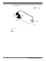
PLANMED SOPHIE
MAMMOGRAPHY X-RAY UNIT
OBL
CC
OBL
LAT
LAT
DEX
SIN
kV
kV
mAs
mAs
CTL
8
3 2 1
TECHNICAL MANUAL
En
788405/11
TABLE OF CONTENTS
Chapter A GENERAL & TECHNICAL DATA
1 WARNINGS . . . . . . . . . . . . . . . . . . . . . . . . . . . . . . . . . . . . . . . . . . . . . . . A-1
2 MANUAL VERSIONS . . . . . . . . . . . . . . . . . . . . . . . . . . . . . . . . . . . . . . . A-2
3 UNIT MODELS . . . . . . . . . . . . . . . . . . . . . . . . . . . . . . . . . . . . . . . . . . . . A-2
4 SOFTWARE REVISIONS & COMPATIBILITY . . . . . . . . . . . . . . . . . . . . A-3
5 HOW TO FIND INFORMATION IN THIS MANUAL . . . . . . . . . . . . . . . . . A-4
6 TECHNICAL SPECIFICATIONS (TOSHIBA E7272 X-RAY TUBE) . . . . A-5
7 USER’S STATEMENT FOR PLANMED SOPHIE
(TOSHIBA E7272 X-RAY TUBE) . . . . . . . . . . . . . . . . . . . . . . . . . . . . . . A-7
7.1 Definition of measurement criteria. . . . . . . . . . . . . . . . . . . . . . . . . . . . . . . . . . . . . . . . A-7
7.2 Toshiba E7272 x-ray tube ratings . . . . . . . . . . . . . . . . . . . . . . . . . . . . . . . . . . . . . . . . A-9
7.3 Cooling curves for x-ray tube. . . . . . . . . . . . . . . . . . . . . . . . . . . . . . . . . . . . . . . . . . . A-10
8 TECHNICAL SPECIFICATIONS (TOSHIBA E7290 X-RAY TUBE) . . . A-11
9 USER’S STATEMENT FOR PLANMED SOPHIE
(TOSHIBA E7290 X-RAY TUBE) . . . . . . . . . . . . . . . . . . . . . . . . . . . . . A-13
9.1 Toshiba E7290 x-ray tube ratings . . . . . . . . . . . . . . . . . . . . . . . . . . . . . . . . . . . . . . . A-15
9.2 Cooling curves for x-ray tube. . . . . . . . . . . . . . . . . . . . . . . . . . . . . . . . . . . . . . . . . . . A-16
Chapter B
UNPACKING & INSTALLATION
1 PRE-INSTALLATION REQUIREMENTS . . . . . . . . . . . . . . . . . . . . . . . . B-1
1.1
1.2
1.3
1.4
1.5
Tools required . . . . . . . . . . . . . . . . . . . . . . . . . . . . . . . . . . . . . . . . . . . . . . . . . . . . . . .
Environmental requirements . . . . . . . . . . . . . . . . . . . . . . . . . . . . . . . . . . . . . . . . . . . .
Space requirement . . . . . . . . . . . . . . . . . . . . . . . . . . . . . . . . . . . . . . . . . . . . . . . . . . .
Radiation protection . . . . . . . . . . . . . . . . . . . . . . . . . . . . . . . . . . . . . . . . . . . . . . . . . .
Power requirement . . . . . . . . . . . . . . . . . . . . . . . . . . . . . . . . . . . . . . . . . . . . . . . . . . .
B-1
B-1
B-1
B-2
B-2
2 UNPACKING THE UNIT . . . . . . . . . . . . . . . . . . . . . . . . . . . . . . . . . . . . . B-3
2.1
2.2
2.3
2.4
2.5
General about unpacking . . . . . . . . . . . . . . . . . . . . . . . . . . . . . . . . . . . . . . . . . . . . . .
Step-by-step unpacking instructions . . . . . . . . . . . . . . . . . . . . . . . . . . . . . . . . . . . . . .
Driving the unit out of the transportation position . . . . . . . . . . . . . . . . . . . . . . . . . . . .
Attaching the unit to the floor. . . . . . . . . . . . . . . . . . . . . . . . . . . . . . . . . . . . . . . . . . . .
Unpacking the accessories . . . . . . . . . . . . . . . . . . . . . . . . . . . . . . . . . . . . . . . . . . . . .
B-3
B-3
B-5
B-6
B-7
3 ATTACHMENT OF ACCESSORIES . . . . . . . . . . . . . . . . . . . . . . . . . . . . B-8
3.1
3.2
3.3
3.4
3.5
3.6
Compression paddles . . . . . . . . . . . . . . . . . . . . . . . . . . . . . . . . . . . . . . . . . . . . . . . . .
Remote control attachment (optional for the mobile unit) . . . . . . . . . . . . . . . . . . . . . .
Mobile Sophie special accessories attachment. . . . . . . . . . . . . . . . . . . . . . . . . . . . . .
Exposure warning light (option). . . . . . . . . . . . . . . . . . . . . . . . . . . . . . . . . . . . . . . . . .
Printer (option). . . . . . . . . . . . . . . . . . . . . . . . . . . . . . . . . . . . . . . . . . . . . . . . . . . . . . .
ADMARK darkroom film-marking system . . . . . . . . . . . . . . . . . . . . . . . . . . . . . . . . . .
B-8
B-8
B-8
B-8
B-8
B-8
4 SETUPS AND CHECKS PRIOR TO USE . . . . . . . . . . . . . . . . . . . . . . . B-9
5 RE-PACKING & TRANSPORTATION OF THE SOPHIE UNIT . . . . . . . B-10
5.1 Driving the unit into the transportation position . . . . . . . . . . . . . . . . . . . . . . . . . . . . . B-10
5.2 Transporting the unit on its own wheels (non-mobile unit). . . . . . . . . . . . . . . . . . . . . B-10
6 MOBILE SOPHIE HANDLING & TRANSPORTATION . . . . . . . . . . . . . B-11
6.1 Preparing the mobile unit for use after transportation . . . . . . . . . . . . . . . . . . . . . . . . B-11
6.2 Preparing the mobile unit for transportation . . . . . . . . . . . . . . . . . . . . . . . . . . . . . . . B-12
Chapter C KEYBOARD FUNCTIONS & MODES
1 KEYBOARD OVERVIEW . . . . . . . . . . . . . . . . . . . . . . . . . . . . . . . . . . . . C-1
2 USER MODE FUNCTIONS SHORT-FORM . . . . . . . . . . . . . . . . . . . . . . C-2
2.1 Normal user functions . . . . . . . . . . . . . . . . . . . . . . . . . . . . . . . . . . . . . . . . . . . . . . . . . C-2
2.2 Special user settings . . . . . . . . . . . . . . . . . . . . . . . . . . . . . . . . . . . . . . . . . . . . . . . . . . C-2
3 SERVICE MODE FUNCTIONS SHORT-FORM . . . . . . . . . . . . . . . . . . . C-4
3.1 How to enter / exit the service mode . . . . . . . . . . . . . . . . . . . . . . . . . . . . . . . . . . . . . . C-4
Technical Manual
Sophie Mammography X-ray unit
TOC-1
TABLE OF CONTENTS
3.2 Meaning of displays in the service mode . . . . . . . . . . . . . . . . . . . . . . . . . . . . . . . . . . C-4
3.3 Service mode settings & special displays . . . . . . . . . . . . . . . . . . . . . . . . . . . . . . . . . . C-5
4 SERVICE MODE FUNCTION DETAILS . . . . . . . . . . . . . . . . . . . . . . . . . C-7
4.1
4.2
4.3
4.4
4.5
4.6
4.7
4.8
Transport position . . . . . . . . . . . . . . . . . . . . . . . . . . . . . . . . . . . . . . . . . . . . . . . . . . . . C-7
Display of internal temperatures . . . . . . . . . . . . . . . . . . . . . . . . . . . . . . . . . . . . . . . . . C-7
Displaying the real density value . . . . . . . . . . . . . . . . . . . . . . . . . . . . . . . . . . . . . . . . . C-8
Displaying the exposure counter . . . . . . . . . . . . . . . . . . . . . . . . . . . . . . . . . . . . . . . . . C-8
Displaying the recent 49 error messages . . . . . . . . . . . . . . . . . . . . . . . . . . . . . . . . . . C-8
Print a list of the recent 49 errors . . . . . . . . . . . . . . . . . . . . . . . . . . . . . . . . . . . . . . . . C-9
Ignore errors temporarily . . . . . . . . . . . . . . . . . . . . . . . . . . . . . . . . . . . . . . . . . . . . . . . C-9
Diagnostic display of internal signals . . . . . . . . . . . . . . . . . . . . . . . . . . . . . . . . . . . . C-10
Chapter D HELP AND ERROR MESSAGES
1 GENERAL ABOUT ERROR DISPLAYS . . . . . . . . . . . . . . . . . . . . . . . . . D-1
1.1 Stop-message . . . . . . . . . . . . . . . . . . . . . . . . . . . . . . . . . . . . . . . . . . . . . . . . . . . . . . . D-1
1.2 Help messages . . . . . . . . . . . . . . . . . . . . . . . . . . . . . . . . . . . . . . . . . . . . . . . . . . . . . . D-1
1.3 Error messages . . . . . . . . . . . . . . . . . . . . . . . . . . . . . . . . . . . . . . . . . . . . . . . . . . . . . . D-1
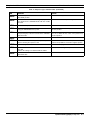
2 HELP MESSAGES SHORTFORM TABLE . . . . . . . . . . . . . . . . . . . . . . . D-2
3 ERROR MESSAGES SHORTFORM TABLE . . . . . . . . . . . . . . . . . . . . . D-4
4 DETAILED ERROR MESSAGE EXPLANATIONS . . . . . . . . . . . . . . . . . D-8
4.1 ERRORS 00-09 (User related, not stored in internal error list) . . . . . . . . . . . . . . . . . . D-8
4.2 ERRORS 10-16 (X-ray safety and AEC-sensor related) . . . . . . . . . . . . . . . . . . . . . . . D-9
4.3 ERRORS 20-29 (motion and compression related) . . . . . . . . . . . . . . . . . . . . . . . . . D-10
4.4 ERRORS 30-38 (tube head and power supply related) . . . . . . . . . . . . . . . . . . . . . . D-12
4.5 ERRORS 40-49 (sensor & switch related) . . . . . . . . . . . . . . . . . . . . . . . . . . . . . . . . D-13
4.6 ERRORS 50-59 (temperature & special sensor related). . . . . . . . . . . . . . . . . . . . . . D-15
4.7 ERRORS 60-68 (serial communication & CPU voltage related) . . . . . . . . . . . . . . . . D-16
4.8 ERRORS 71-78 (CPU software related) . . . . . . . . . . . . . . . . . . . . . . . . . . . . . . . . . . D-16
4.9 ERRORS 80-87 (CPU hardware related) . . . . . . . . . . . . . . . . . . . . . . . . . . . . . . . . . D-17
4.10 ERRORS 90-97 (Erroneous sensor signals) . . . . . . . . . . . . . . . . . . . . . . . . . . . . . . D-18
Chapter E
PREVENTIVE MAINTENANCE
1 SYSTEM MAINTENANCE . . . . . . . . . . . . . . . . . . . . . . . . . . . . . . . . . . . E-1
1.1 Cleaning . . . . . . . . . . . . . . . . . . . . . . . . . . . . . . . . . . . . . . . . . . . . . . . . . . . . . . . . . . . E-1
1.2 Operator’s maintenance schedule. . . . . . . . . . . . . . . . . . . . . . . . . . . . . . . . . . . . . . . . E-1
2 PREVENTIVE MAINTENANCE CHECKS . . . . . . . . . . . . . . . . . . . . . . . E-2
2.1
2.2
2.3
2.4
2.5
2.6
2.7
Preventive maintenance schedule. . . . . . . . . . . . . . . . . . . . . . . . . . . . . . . . . . . . . . . .
Calibration and verification of the instruments . . . . . . . . . . . . . . . . . . . . . . . . . . . . . .
Determining half value layer (HVL / beam quality) . . . . . . . . . . . . . . . . . . . . . . . . . . .
Checking X-ray tube efficiency (radiation output) . . . . . . . . . . . . . . . . . . . . . . . . . . . .
Focal spot size measurement. . . . . . . . . . . . . . . . . . . . . . . . . . . . . . . . . . . . . . . . . . .
Image quality evaluation . . . . . . . . . . . . . . . . . . . . . . . . . . . . . . . . . . . . . . . . . . . . . . .
Verifying AEC-system control limits. . . . . . . . . . . . . . . . . . . . . . . . . . . . . . . . . . . . . . .
E-2
E-2
E-3
E-4
E-4
E-5
E-5
3 OTHER PREVENTIVE CHECKS . . . . . . . . . . . . . . . . . . . . . . . . . . . . . . E-6
3.1
3.2
3.3
3.4
3.5
3.6
3.7
3.8
3.9
Chapter F
Verifying compression force measurement . . . . . . . . . . . . . . . . . . . . . . . . . . . . . . . . . E-6
Verifying filament pre-heating voltages . . . . . . . . . . . . . . . . . . . . . . . . . . . . . . . . . . . . E-6
Verifying the anode voltage (kV) . . . . . . . . . . . . . . . . . . . . . . . . . . . . . . . . . . . . . . . . . E-6
Verifying the tube current (mA) and the exposure time (Toshiba E7272 x-ray tube) . . E-8
Verifying the tube current (mA) and the exposure time (Toshiba E7290 x-ray tube) . . E-9
Verifying x-ray beam alignment . . . . . . . . . . . . . . . . . . . . . . . . . . . . . . . . . . . . . . . . . E-10
Verifying light-field beam illumination . . . . . . . . . . . . . . . . . . . . . . . . . . . . . . . . . . . . E-10
Verifying visually defined x-ray fields . . . . . . . . . . . . . . . . . . . . . . . . . . . . . . . . . . . . . E-11
Verifying electrical safety . . . . . . . . . . . . . . . . . . . . . . . . . . . . . . . . . . . . . . . . . . . . . . E-11
ADJUSTMENT & CALIBRATION
1 SPECIAL REGIONAL & INITIAL SETUPS . . . . . . . . . . . . . . . . . . . . . . F-1
1.1 Regional setups before using the unit . . . . . . . . . . . . . . . . . . . . . . . . . . . . . . . . . . . . . F-1
1.2 Other setups before using the unit . . . . . . . . . . . . . . . . . . . . . . . . . . . . . . . . . . . . . . . F-1
TOC-2
Sophie Mammography X-ray unit
Technical Manual
TABLE OF CONTENTS
2 KEYBOARD-CONTROLLED (in normal mode) . . . . . . . . . . . . . . . . . . F-3
2.1 Automatic kV mode . . . . . . . . . . . . . . . . . . . . . . . . . . . . . . . . . . . . . . . . . . . . . . . . . . .
2.2 Automatic rhodium/molybdenum filter selection mode . . . . . . . . . . . . . . . . . . . . . . . .
2.3 Default magnification factor . . . . . . . . . . . . . . . . . . . . . . . . . . . . . . . . . . . . . . . . . . . . .
2.4 Automatic release of compression after exposure. . . . . . . . . . . . . . . . . . . . . . . . . . . .
2.5 Initial descent speed . . . . . . . . . . . . . . . . . . . . . . . . . . . . . . . . . . . . . . . . . . . . . . . . . .
2.6 Compression speed decrease rate . . . . . . . . . . . . . . . . . . . . . . . . . . . . . . . . . . . . . . .
2.7 Intermediate compression stopping force . . . . . . . . . . . . . . . . . . . . . . . . . . . . . . . . . .
2.8 Twincomp compression on/off . . . . . . . . . . . . . . . . . . . . . . . . . . . . . . . . . . . . . . . . . . .
2.9 Lift motor crawling speed. . . . . . . . . . . . . . . . . . . . . . . . . . . . . . . . . . . . . . . . . . . . . . .
2.10 Setting correct time and date . . . . . . . . . . . . . . . . . . . . . . . . . . . . . . . . . . . . . . . . . . .
2.11 Density offset adjustment. . . . . . . . . . . . . . . . . . . . . . . . . . . . . . . . . . . . . . . . . . . . . .
2.12 AAEC contrast adjustment . . . . . . . . . . . . . . . . . . . . . . . . . . . . . . . . . . . . . . . . . . . . .
2.13 Automatic film labeling (on/off). . . . . . . . . . . . . . . . . . . . . . . . . . . . . . . . . . . . . . . . . .
2.14 Disabling bucky grid movement . . . . . . . . . . . . . . . . . . . . . . . . . . . . . . . . . . . . . . . . .
2.15 Alarm sound frequency (loudness) . . . . . . . . . . . . . . . . . . . . . . . . . . . . . . . . . . . . . .
2.16 Dimming the displays . . . . . . . . . . . . . . . . . . . . . . . . . . . . . . . . . . . . . . . . . . . . . . . . .
2.17 mA limit (on/off) . . . . . . . . . . . . . . . . . . . . . . . . . . . . . . . . . . . . . . . . . . . . . . . . . . . . .
F-3
F-3
F-4
F-4
F-4
F-5
F-5
F-5
F-5
F-6
F-6
F-6
F-6
F-7
F-7
F-7
F-7
3 KEYBOARD-CONTROLLED (in service mode) . . . . . . . . . . . . . . . . . . F-8
3.1
3.2
3.3
3.4
3.5
3.6
3.7
3.8
3.9
How to enter the service mode . . . . . . . . . . . . . . . . . . . . . . . . . . . . . . . . . . . . . . . . . . F-8
Factory preset (recalling settings for all parameters). . . . . . . . . . . . . . . . . . . . . . . . . . F-9
C-arm upright position calibration . . . . . . . . . . . . . . . . . . . . . . . . . . . . . . . . . . . . . . . F-12
Breast thickness measurement calibration . . . . . . . . . . . . . . . . . . . . . . . . . . . . . . . . F-12
Compression force measurement calibration . . . . . . . . . . . . . . . . . . . . . . . . . . . . . . F-13
X- ray tube filament preheating voltage calibration . . . . . . . . . . . . . . . . . . . . . . . . . . F-14
AEC-sensor calibration . . . . . . . . . . . . . . . . . . . . . . . . . . . . . . . . . . . . . . . . . . . . . . . F-15
kV-value fine-adjustment . . . . . . . . . . . . . . . . . . . . . . . . . . . . . . . . . . . . . . . . . . . . . . F-16
Special system parameters setup . . . . . . . . . . . . . . . . . . . . . . . . . . . . . . . . . . . . . . . F-17
4 FINE TUNING SOPHIE AEC FOR NONSTANDARD FILM/SCREEN
COMBINATIONS . . . . . . . . . . . . . . . . . . . . . . . . . . . . . . . . . . . . . . . . . . F-24
4.1
4.2
4.3
4.4
Background . . . . . . . . . . . . . . . . . . . . . . . . . . . . . . . . . . . . . . . . . . . . . . . . . . . . . . . .
Testing the AEC for proper tracking. . . . . . . . . . . . . . . . . . . . . . . . . . . . . . . . . . . . . .
Adjusting the thickness, tube potential and time compensations . . . . . . . . . . . . . . .
Adjusting the filter and imaging mode adjustments. . . . . . . . . . . . . . . . . . . . . . . . . .
F-24
F-24
F-24
F-26
5 MECHANICAL ADJUSTMENTS . . . . . . . . . . . . . . . . . . . . . . . . . . . . . F-28
5.1
5.2
5.3
5.4
5.5
5.6
5.7
5.8
MAG/LOAD mechanism positional calibration. . . . . . . . . . . . . . . . . . . . . . . . . . . . . .
UP/DOWN mechanism positional calibration . . . . . . . . . . . . . . . . . . . . . . . . . . . . . .
X-ray beam adjustment (Toshiba E7272 X-ray tube) . . . . . . . . . . . . . . . . . . . . . . . . .
X-ray beam adjustment (Toshiba E7290 X-ray tube) . . . . . . . . . . . . . . . . . . . . . . . . .
Light field beam adjustment . . . . . . . . . . . . . . . . . . . . . . . . . . . . . . . . . . . . . . . . . . .
Filter position adjustment . . . . . . . . . . . . . . . . . . . . . . . . . . . . . . . . . . . . . . . . . . . . .
Twincomp paddle damper adjustment . . . . . . . . . . . . . . . . . . . . . . . . . . . . . . . . . . . .
Gas spring tension adjustment . . . . . . . . . . . . . . . . . . . . . . . . . . . . . . . . . . . . . . . . .
F-28
F-28
F-29
F-35
F-42
F-43
F-43
F-43
6 ADJUSTING SENSORS & SWITCHES . . . . . . . . . . . . . . . . . . . . . . . . F-44
6.1
6.2
6.3
6.4
6.5
6.6
6.7
6.8
Collimator mechanism limit sensors . . . . . . . . . . . . . . . . . . . . . . . . . . . . . . . . . . . . .
Compression mechanism limit sensors. . . . . . . . . . . . . . . . . . . . . . . . . . . . . . . . . . .
MAG/LOAD mechanism limit sensors . . . . . . . . . . . . . . . . . . . . . . . . . . . . . . . . . . . .
Labeling head disk position sensor . . . . . . . . . . . . . . . . . . . . . . . . . . . . . . . . . . . . . .
C-arm rotation sensor . . . . . . . . . . . . . . . . . . . . . . . . . . . . . . . . . . . . . . . . . . . . . . . .
UP/DOWN mechanism sensors . . . . . . . . . . . . . . . . . . . . . . . . . . . . . . . . . . . . . . . .
Cassette table size identification switches. . . . . . . . . . . . . . . . . . . . . . . . . . . . . . . . .
Lower paddle identification switches . . . . . . . . . . . . . . . . . . . . . . . . . . . . . . . . . . . . .
F-44
F-49
F-52
F-54
F-54
F-58
F-61
F-64
Chapter G TROUBLESHOOTING & FAULTFINDING
1 DISPLAYING INTERNAL SENSOR SIGNALS . . . . . . . . . . . . . . . . . . . . G-1
2 ELECTRICAL PROBLEMS . . . . . . . . . . . . . . . . . . . . . . . . . . . . . . . . . . G-1
2.1 Unit completely dead. . . . . . . . . . . . . . . . . . . . . . . . . . . . . . . . . . . . . . . . . . . . . . . . . . G-1
3 MOTOR & MOTION RELATED PROBLEMS . . . . . . . . . . . . . . . . . . . . . G-2
3.1 DC motors . . . . . . . . . . . . . . . . . . . . . . . . . . . . . . . . . . . . . . . . . . . . . . . . . . . . . . . . . . G-2
3.2 Stepper motors . . . . . . . . . . . . . . . . . . . . . . . . . . . . . . . . . . . . . . . . . . . . . . . . . . . . . . G-3
Technical Manual
Sophie Mammography X-ray unit
TOC-3
TABLE OF CONTENTS
4 MECHANICAL PROBLEMS . . . . . . . . . . . . . . . . . . . . . . . . . . . . . . . . . . G-6
4.1 Paddle holder related . . . . . . . . . . . . . . . . . . . . . . . . . . . . . . . . . . . . . . . . . . . . . . . . . G-6
5 BEFORE CALLING FOR ASSISTANCE . . . . . . . . . . . . . . . . . . . . . . . . G-8
5.1 General required information. . . . . . . . . . . . . . . . . . . . . . . . . . . . . . . . . . . . . . . . . . . . G-8
5.2 How to report image quality problems. . . . . . . . . . . . . . . . . . . . . . . . . . . . . . . . . . . . . G-8
5.3 How to contact Planmed head office . . . . . . . . . . . . . . . . . . . . . . . . . . . . . . . . . . . . . . G-8
Chapter H PARTS REPLACEMENT & REPAIR
1 REMOVING & REPLACING COVERS . . . . . . . . . . . . . . . . . . . . . . . . . . H-1
1.1
1.2
1.3
1.4
1.5
1.6
1.7
Base covers. . . . . . . . . . . . . . . . . . . . . . . . . . . . . . . . . . . . . . . . . . . . . . . . . . . . . . . . . H-2
Telescopic column covers . . . . . . . . . . . . . . . . . . . . . . . . . . . . . . . . . . . . . . . . . . . . . . H-2
Stationary column covers . . . . . . . . . . . . . . . . . . . . . . . . . . . . . . . . . . . . . . . . . . . . . . H-3
C-arm covers . . . . . . . . . . . . . . . . . . . . . . . . . . . . . . . . . . . . . . . . . . . . . . . . . . . . . . . . H-4
Hood . . . . . . . . . . . . . . . . . . . . . . . . . . . . . . . . . . . . . . . . . . . . . . . . . . . . . . . . . . . . . . H-6
Cassette table cover . . . . . . . . . . . . . . . . . . . . . . . . . . . . . . . . . . . . . . . . . . . . . . . . . . H-7
Collimator cover. . . . . . . . . . . . . . . . . . . . . . . . . . . . . . . . . . . . . . . . . . . . . . . . . . . . . . H-7
2 SOFTWARE VERSION UPDATING . . . . . . . . . . . . . . . . . . . . . . . . . . . . H-8
2.1 Replacing software chips. . . . . . . . . . . . . . . . . . . . . . . . . . . . . . . . . . . . . . . . . . . . . . . H-8
3 REPLACING FUSES . . . . . . . . . . . . . . . . . . . . . . . . . . . . . . . . . . . . . . H-10
3.1 Mains fuses . . . . . . . . . . . . . . . . . . . . . . . . . . . . . . . . . . . . . . . . . . . . . . . . . . . . . . . . H-10
3.2 Power supply fuses . . . . . . . . . . . . . . . . . . . . . . . . . . . . . . . . . . . . . . . . . . . . . . . . . . H-10
4 LIGHTFIELD BULB REPLACEMENT . . . . . . . . . . . . . . . . . . . . . . . . . H-12
5 REPLACING THE X-RAY TUBEHEAD . . . . . . . . . . . . . . . . . . . . . . . . . H-13
5.1 Preparations before changing the tubehead . . . . . . . . . . . . . . . . . . . . . . . . . . . . . . . H-14
5.2 Removal of the tubehead . . . . . . . . . . . . . . . . . . . . . . . . . . . . . . . . . . . . . . . . . . . . . H-17
6 REPLACING THE POWER SUPPLY . . . . . . . . . . . . . . . . . . . . . . . . . . H-18
7 REPLACING CIRCUIT BOARDS . . . . . . . . . . . . . . . . . . . . . . . . . . . . . H-19
7.1
7.2
7.3
7.4
7.5
Location of PC-boards. . . . . . . . . . . . . . . . . . . . . . . . . . . . . . . . . . . . . . . . . . . . . . . .
Boards in the base & column . . . . . . . . . . . . . . . . . . . . . . . . . . . . . . . . . . . . . . . . . .
C-arm pc-boards . . . . . . . . . . . . . . . . . . . . . . . . . . . . . . . . . . . . . . . . . . . . . . . . . . . .
Tubehead assembly boards. . . . . . . . . . . . . . . . . . . . . . . . . . . . . . . . . . . . . . . . . . . .
Keyboards & displays . . . . . . . . . . . . . . . . . . . . . . . . . . . . . . . . . . . . . . . . . . . . . . . .
H-19
H-20
H-20
H-22
H-22
8 REPLACING SENSORS & SWITCHES . . . . . . . . . . . . . . . . . . . . . . . . H-23
8.1
8.2
8.3
8.4
8.5
Placement of sensors & switches . . . . . . . . . . . . . . . . . . . . . . . . . . . . . . . . . . . . . . .
Limit sensors . . . . . . . . . . . . . . . . . . . . . . . . . . . . . . . . . . . . . . . . . . . . . . . . . . . . . . .
Lift motor rotation sensor replacement . . . . . . . . . . . . . . . . . . . . . . . . . . . . . . . . . . .
C-arm motor rotation sensor replacement. . . . . . . . . . . . . . . . . . . . . . . . . . . . . . . . .
MAG-motor rotation sensor replacement . . . . . . . . . . . . . . . . . . . . . . . . . . . . . . . . .
H-23
H-24
H-24
H-25
H-25
9 MOTOR REPLACEMENT . . . . . . . . . . . . . . . . . . . . . . . . . . . . . . . . . . . H-26
9.1
9.2
9.3
9.4
Lift motor replacement. . . . . . . . . . . . . . . . . . . . . . . . . . . . . . . . . . . . . . . . . . . . . . . . H-26
C-arm rotation motor replacement . . . . . . . . . . . . . . . . . . . . . . . . . . . . . . . . . . . . . . H-28
Compression motor replacement . . . . . . . . . . . . . . . . . . . . . . . . . . . . . . . . . . . . . . . H-34
Magnification motor replacement . . . . . . . . . . . . . . . . . . . . . . . . . . . . . . . . . . . . . . . H-35
10 REPLACING THE LABELING HEAD . . . . . . . . . . . . . . . . . . . . . . . . . . H-37
11 GAS SPRING REPLACEMENT . . . . . . . . . . . . . . . . . . . . . . . . . . . . . . H-38
11.1 C-arm is functional . . . . . . . . . . . . . . . . . . . . . . . . . . . . . . . . . . . . . . . . . . . . . . . . . . H-38
11.2 C-arm is not rotating . . . . . . . . . . . . . . . . . . . . . . . . . . . . . . . . . . . . . . . . . . . . . . . . H-38
11.3 Replacing the gas-spring . . . . . . . . . . . . . . . . . . . . . . . . . . . . . . . . . . . . . . . . . . . . . H-38
12 REPLACING PARTS IN COMPRESSION MECHANISM . . . . . . . . . . . H-39
12.1 Replacing the twin-comp damper. . . . . . . . . . . . . . . . . . . . . . . . . . . . . . . . . . . . . . . H-39
Chapter I
SCHEMATICS & DIAGRAMS
COPYRIGHT PLANMED 2000-10
PUBLICATION NUMBER 788405 revision 11
TOC-4
Sophie Mammography X-ray unit
Technical Manual
Chapter
A
1
GENERAL & TECHNICAL DATA
WARNINGS
WARNING
THE FOLLOWING WARNINGS, CAUTIONS AND NOTES MUST ALWAYS BE CONSIDERED
WHILE SERVICING, IN ORDER TO AVOID EITHER PERSONAL INJURY OR DAMAGE TO
THE UNIT.
CAUTION
RADIATION SAFETY RULES
Some procedures described in this manual produces X-ray radiation. Always follow rules
for radiation safety.
Never touch or scratch the surface of the x-ray tube radiation window. The window is
made of beryllium that can be harmful if inhaled or swallowed.
Never attempt to open the TUBE-HEAD. It does not contain any serviceable parts and this
would make it inoperable and void the warranty.
Never make any exposures without the Mo/Al filter in the beam, or without the beam limiting device (collimator) in place. Otherwise the radiation safety cannot be guaranteed.
CAUTION
ELECTRICAL SAFETY RULES
The unit contains hazardous voltages. While servicing internal parts, always disconnect
the unit from the mains (if possible) by removing the plug from the wall outlet, and wait for
2 minutes before touching any electrical parts.
Always replace the fuses with ones of the same type and rating. Otherwise patient, operator or equipment safety cannot be guaranteed.
The circuit boards can be damaged due to static discharges and requires careful handling
and storage.
CAUTION
GENERAL SAFETY RULES
The unit must be serviced only by qualified personnel, trained by PLANMED Repairs and
parts replaced by unqualified personnel carry no warranty.
Periodical maintenance as described in this manual must be performed on a regular basis,
to ensure the safety and image quality of the unit.
Some procedures described in the unit could jeopardize the function of the unit, if not followed as stated.
Technical Manual
Sophie Mammography X-ray unit A-1
Chapter A - GENERAL & TECHNICAL DATA
2
MANUAL VERSIONS
MANUAL VERSIONS
PLANMED pursues a policy of continuous product development. Although every effort is made to
produce up-to-date product documentation this manual should not be regarded as an infallible
guide to current production specifications. Planmed reserves the right to make changes to specifications without prior notice. This manual is valid for all versions of the Sophie Mammography X-ray units with SID 650mm. In case you have the unit with SID 600mm, you need a
technical manual revision 9.
NOTE
THIS TECHNICAL MANUAL IS VALID FOR SOFTWARE REVISIONS: TUBE CPU 2.41
(OR LATER) AND REAR CPU 4.41 (OR LATER).
If you find that your SOPHIE doesn’t have some keyboard functions, or its keyboard
functions differs from procedures described in this manual, then either the software
must be replaced with at least the above mentioned revision, or you have to relate to
an older version of this manual. The former procedure is recommended.
3
UNIT MODELS
All Sophie Mammography X-ray unit models are electrically and mechanically identical, except
for some minor details. This manual is valid for all versions since the differences are small.
The darkroom versus daylight differs only in the size and dimensions of the cassette table and
film marking device.
The mobile versus the stationary units differs only in the base wheel system and the X-ray tube
locking system (for transportation).
Daylight units can be converted to darkroom units (and vice versa), please contact PLANMED for
details.
A-2
Sophie Mammography X-ray unit
Technical Manual
Chapter A - GENERAL & TECHNICAL DATA
4
SOFTWARE REVISIONS & COMPATIBILITY
SOFTWARE REVISIONS & COMPATIBILITY
Background
Since this unit is fully microprocessor controlled, its operation is controlled by the currently
installed software. PLANMED reserves the right to improve functionality or to add new features to
the product by modifying the software and/or hardware. Manuals are updated accordingly and
technical bulletins published in order to inform about these changes or additions.
Hardware compatibility
As a general rule; new software releases are compatible with all existing hardware. New software
releases (or possible upgrading kits containing new software) are normally directly compatible
with existing hardware, but not necessarily without some re-calibration procedures.
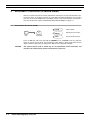
Software numbering & compatibility
Since the unit contains two communicating microprocessors, these must be able to “understand”
each other.
Incompatible software versions should never be used together, the unit would either be totally
non-functional, produce continuous error codes, or some important features or functions could be
missing. However, no damage or safety hazard would result if two non-compatible software chips
are accidentally used together.
The following table contains information about compatible software versions. Use versions
together only as listed in this table.
Table 1: SOFTWARE COMPATIBILITY LIST
REAR CPU
1.20 - 1.28
1.59
1.60
1.63
1.64
1.65
1.66
1.67
1.68
1.69
1.70
1.71
1.72
1.73
1.74
1.75
1.76
1.77
Technical Manual
TUBE CPU
1.20 - 1.28
1.59
1.60
1.63
1.64
1.64
1.64
1.64
1.64
1.69
1.69
1.69
1.69
1.69
1.69
1.69, 1.70
1.75, 1.76
1.77, 1.78,
1.79
REAR CPU
1.80
1.81
4.00
4.01/2.01
4.02/2.02
4.06/2.06
4.20
4.21
4.22
4.23
4.30
4.40
4.41
TUBE CPU
1.80, 2.00
1.81, 2.01
2.01
2.04
2.04
2.04
2.20
2.22
2.23
2.25
2.31
2.40
2.41
Sophie Mammography X-ray unit
A-3
Chapter A - GENERAL & TECHNICAL DATA
5
HOW TO FIND INFORMATION IN THIS MANUAL
HOW TO FIND INFORMATION IN THIS MANUAL
For normal operating instructions, please refer to the “SOPHIE USER’S MANUAL”. However,
this manual contains also full explanations of all user accessible adjustments that can be done
with the keyboards.
For navigation, please refer to the table of contents in the beginning of this manual. The following is a brief description of the chapters in this manual.
“GENERAL & TECHNICAL DATA” on page A-1 (this chapter)
This chapter contains general information as well detailed technical specifications of the unit.
Here you can find answers to all questions related to the unit specifications. Full technical specification details can be found here.
“UNPACKING & INSTALLATION” on page B-1
This chapter contains complete instructions how to unpack and install the unit, with information
about installation requirements. Also information about transportation and handling is included.
“KEYBOARD FUNCTIONS & MODES” on page C-1
This chapter contains a complete short-form presentation of all available special keyboard functions. For explanation of normal user operation. Please refer to the “SOPHIE USER’S MANUAL”.
The special display modes are also described here.
The detailed descriptions of all adjustments performed with the help of the keyboards can be
found in the chapter “ADJUSTMENT & CALIBRATION” on page F-1.
“HELP AND ERROR MESSAGES” on page D-1
This chapter contains general information as well as a complete short-form presentation of all
available special messages (STOP, HELP, ERROR) that can appear on the displays. A detailed
description of the error messages and their reasons is also included.
“PREVENTIVE MAINTENANCE” on page E-1
This chapter describes the operators maintenance. Complete step-by-step instructions how to
check the performance of the unit are also included. Some of these checks must be performed
annually and before using the unit.
“ADJUSTMENT & CALIBRATION” on page F-1
This chapter contains detailed instructions of how to perform keyboard-controlled adjustments
and calibrations, mechanical adjustments and sensor & switch adjustments.
“GENERAL & TECHNICAL DATA” on page A-1
For help and guidance with general troubleshooting and faultfinding, please refer to this chapter.
It contains information of how to proceed in possible problematic situations.
“PARTS REPLACEMENT & REPAIR” on page H-1
This chapter contains detailed instructions how to replace both mechanical and electrical parts. It
also reminds of what possible calibrations or adjustments must be performed after replacing particular parts.
“SCHEMATICS & DIAGRAMS” on page I-1
This chapter contains electrical wiring diagrams and schematics.
A-4
Sophie Mammography X-ray unit
Technical Manual
Chapter A - GENERAL & TECHNICAL DATA
6
TECHNICAL SPECIFICATIONS (TOSHIBA E7272 X-RAY
TECHNICAL SPECIFICATIONS (TOSHIBA E7272 X-RAY TUBE)
ORIGINAL MANUFACTURER
PLANMED Oy, Asentajankatu 6, 00810 Helsinki, FINLAND
phone: +358-9-7590 5300, fax: +358-9-7590 5555
MODEL AND APPROVALS
MODELS:
APPROVALS:
PLANMED SOPHIE, PLANMED SOPHIE MOBILE
IEC safety class: I, IEC degree of protection: B, IEC enclosure class: IP20
Complies with IEC 601-1 safety and IEC 601-2-7 radiation regulations
X-RAY TUBE ASSEMBLY
X-ray tube
Anode type
Anode braking
Anode thermal capacity
Anode target material
Anode target angle
Tube port material
Focal spot sizes
Filtration
Toshiba E7272
rotating anode (3000 rpm at 50 Hz)
Automatic, electrical
300 000 HU
Molybdenum
16 degrees
Beryllium
0.3mm / 0.1 x 0.07 mm
30µm Mo and 0.5mm Al or
30µm Mo and 25µm Rh
GENERATOR ASSEMBLY (for both tube types if not otherwise specified)
Generator
Anode voltage range
Anode current range/0.3mm focus
Anode current range/0.1mm focus
mAs range/0.3mm focus
mAs range/ 0.1mm focus
Exposure time /0.3mm focus
Exposure time / 0.1mm focus
Cooling
Line voltage
Line voltage compensation
Line voltage regulation
Fuses
Total power consumption
Power factor
Mode of operation
Maximum mains resistance
Maximum continuous
heat dissipation
constant potential, high frequency
20 - 35kV ± 2kV, virtually DC
70 - 110mA (70 - 120 mA @ 60Hz) ± 5mA
10 - 22mA (12 - 22 mA @ 60Hz) ± 1mA
10 - 500mAs (optional 600mAs in GB) ± 4mAs
or ±10% (whichever is larger)
10 - 200 mAs
0.1 - 5 seconds (optional 6 seconds) ±5%
0.1 - 9.9 seconds ±5%
automatically controlled (internal fan)
208 - 240V~, 50 or 60Hz - single phase
automatic ±10%
±10% (absolute minimum/maximum 187V~/265V~)
2 x 15AT / 250V
max. 100VA idle, 4000VA max. for 5 seconds
> 0.95
intermittent
Ω1¾
< 250W
BUCKY GRID SPECIFICATION
Grid manufacturer
Grid type
Grid movement
Grid ratio
Grid lines per cm
Focusing distance
Application limits
Gilardoni
GRIDGIL HT; Fiber interspaced vertical
Variable amplitude oscillation
r5
N36
f065
18x24: f150 f291
24x30: f153 f282
Material of absorbing strips
Pb
Contrast improvement ratio
K1.47
Selectivity
Σ6.04
Grid exposure factor
B1.69
Transmission of primary radiation Tp 0.75
Max. deviation between the central
line indication and the true
central line
∆2
Technical Manual
Sophie Mammography X-ray unit
A-5
Chapter A - GENERAL & TECHNICAL DATA
TECHNICAL SPECIFICATIONS (TOSHIBA E7272 X-RAY
AUTOMATIC EXPOSURE CONTROL (AEC)
Sensors
Density adjustment
Function modes
three selectable large area solid-state sensors
15 density steps (13% change in OD per step)
plus fine adjustment ± 5 steps (0,05 OD per step)
Normal AEC, Advanced AEC (AAEC)
C-ARM
Rotation
Vertical movement
SID
Compression
Cassette sizes
Magnification
motorized, range -135° to +180°
motorized, range 795mm to 1350mm (31.3in to 53.1in)
650mm
fully motorized, variable speed, variable angle (twincomp)
18 x 24cm and 24 x 30cm
motorized, variable range from 1.3 to 1.8
MECHANICAL DATA
Dimensions
Weight
Color
A-6
Sophie Mammography X-ray unit
(H x D x W) 1000 x 900 x 755 (mm) minimum
(36.6 x 35.0 x 29.7 inch minimum)
160kg (352lbs), unpacked
RAL 9016
Technical Manual
Chapter A - GENERAL & TECHNICAL DATA
USER’S STATEMENT FOR PLANMED SOPHIE (TOSHIBA
7 USER’S STATEMENT FOR PLANMED SOPHIE (TOSHIBA E7272 X-RAY
TUBE)
Radiation leakage technique factors
The maximum-rated peak tube potential is 35 kVp and the maximum rated continuous tube current is 3.5mA for the maximum-rated peak tube voltage.
Minimum filtration
The Beam-limiting device contains three different filtrations 30µm molybdenum, 25µm rhodium
and 0.50mm aluminum. The measured half-value layers are 0.343mmAl, 0.373mmAl and
0.377mmAl at 30kVp. These measured values correspond to aluminum equivalents of 0.55 0.65mmAl.
Rate line voltage
208 - 240V~ ±10%. Line voltage regulation 10%.
Maximum line current
Maximum 22 Amperes at absolute minimum stated mains voltage (187V~)
Technique factors that constitute the maximum line current condition
27kV / 110mA
Generator rating and duty cycle
3kW. The duty cycle and wait period can be calculated using the following formulas:
•
Wait period = Tw = kV* mA* exp. Time / 500W
•
Duty Cycle = 1 / (1 + kV* mA / 500W)
Maximum deviation of peak tube potential from indicated value
±2kV
Maximum deviation of tube current from indicated value
±5mA large focal spot, ±1mA small focal spot
Maximum deviation of exposure time tube current product from indicated value
±4mAs or ±10%, whichever is larger
Maximum deviation of exposure time from indicated value
±5%
7.1
Definition of measurement criteria
Exposure time
The beginning and end points of the exposure time are defined at 70% of the peak radiation
waveform measured with a calibrated x-ray monitor.
Peak tube potential
Is defined as the measured high voltage mean value measured with a calibrated non-invasive
kVp meter.
Tube current
Is defined using the resistance and voltage over the feedback resistor measured with a calibrated
multimeter. The mA value is then the voltage divided by the resistance.
mAs product
Is defined as the product of the exposure time and the tube current measurements.
The nominal x-ray voltage together with the highest x-ray tube current obtainable
from the high-voltage generator when operated at its nominal x-ray tube voltage
35kV 80mA / 60Hz - large focal spot, 35kV 70mA / 50Hz - large focal spot
35kV 16mA / 60Hz - small focal spot, 35kV 14mA / 50Hz - small focal spot
Technical Manual
Sophie Mammography X-ray unit
A-7
Chapter A - GENERAL & TECHNICAL DATA
USER’S STATEMENT FOR PLANMED SOPHIE (TOSHIBA
The highest x-ray tube current together with the highest x-ray tube voltage obtainable
from the high-voltage generator when operated at its highest x-ray tube current
120mA 24kV / 60Hz - large focal spot, 110mA 24kV / 50Hz - large focal spot
22mA 26kV / 60Hz - small focal spot, 22mA 24kV / 50Hz - small focal spot
The x-ray tube voltage and x-ray tube current which result in the highest electric output
power
27kV 110mA / 60Hz - large focal spot, 34kV 80mA / 50Hz - large focal spot
26kV 22mA / 60Hz - small focal spot, 24kV 22mA / 50Hz - small focal spot
The nominal electric power for a load time of 0.1s and at the nominal x-ray tube voltage
35kV 80mA / 60Hz - 2800W large focal spot, 35kV 70mA / 50Hz - 2450W large focal spot
35kV 16mA / 60Hz - 560W small focal spot, 35kV 14mA / 50Hz - 490W small focal spot
Reference current time product
large focal spot: for all kV values
small focal spot: for all kV values
40mA / 0.1s / 4mAs
10mA / 0.1s / 1mAs
The lowest current time product within the specified range of compliance
large focal spot:
small focal spot:
30mA / 0.1s / 3mAs
10mA / 0.1s / 1mAs
The nominal shortest irradiation time in the AEC-mode
20ms
A-8
Sophie Mammography X-ray unit
Technical Manual
Chapter A - GENERAL & TECHNICAL DATA
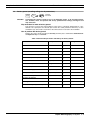
7.2
USER’S STATEMENT FOR PLANMED SOPHIE (TOSHIBA
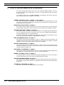
Toshiba E7272 x-ray tube ratings
Manual exposures
With manual exposures the tube kV, mAs and focal spot can be selected by the user. The mA
value is automatically determined by the selected kV value, and the exposure time is determined
by the selected mAs value. The mA value used is always the highest possible value, that
depends on the kV value, focal spot, exposure time and line frequency (see following table on the
next page). The maximum exposure time is 6.0 sec. for the large focal spot, and 9.9 sec. for the
small focal spot. The minimum mAs value is 10 mAs and it can be increased in approx. 20%
steps to the maximum (see values below). The maximum mAs value for the large focal spot is
either 300, 500, 550 or 600 mAs, depending on the value of the service mode parameter 6. The
maximum mAs value for the small focal spot is 200 mAs.
The possible mAs values are: 10, 12, 14, 16, 18, 20, 25, 30, 35, 40, 50, 60, 70, 85, 100, 120, 140,
160, 180, 200, 225, 260, 300, 350, 400, 450, 500, 550, 600.
Automatic exposures
Automatic exposures are terminated when the radiation detector indicates that the required dose
has been reached. In this mode the kV is selected by the operator and mA is chosen to be the
maximum allowed mA for the selected kV and Hz (line frequency).
If the exposure time is longer than 1 sec (5 sec for the small focal spot) then a falling load technique is used. The exposure is started at the mA as specified in the following tables. The accumulated dose is checked at 0.45 sec (2.45 sec for the small focal spot) and if it has reached more
than half of the required dose, the exposure can be continued at the same mA level, and will be
terminated within 1 second (5 seconds for the small focal spot) - well before the tube is overloaded.
If the accumulated dose is detected to be less than half of the required, a longer exposure time
than the one specified for the tube current can be expected. Therefore the tube current is
reduced at this time (after 0.45 or 2.45 sec exposure) to a lower mA that, when added to the
already produced tube loading, will not exceed the maximum tube rating. The falling load current
levels are listed in the two following tables.
Thermal ratings
Two separate methods are used to protect the tube from overload. One is measuring the tube
head enclosure temperature and if it exceeds 60 °C no further exposures are allowed until it falls
below 60 °C.
The other method keeps the average input power into the tube below or equal to 500W. The
exposure parameters are limited as indicated by the following tables, but this feature forces a
waiting time between the exposures to ensure that the average power into the tube never can
exceed this limit. For example if an exposure of 24 kV, 100 mA, 1 sec is performed a wait period
of 5 seconds is calculated and no further exposures are allowed until this time has elapsed.
There is no way to bypass these safety feature under any circumstances, and it is thus virtually
impossible to overload the X-ray tube.
Technical Manual
Sophie Mammography X-ray unit
A-9
Chapter A - GENERAL & TECHNICAL DATA
USER’S STATEMENT FOR PLANMED SOPHIE (TOSHIBA
Table 2: Maximum mA for Tube E7272 vs. different modes and line frequencies
MANUAL EXPOSURE MODE
Large focal spot
(0.3 mm)
0-1
sec
1-5
sec
AUTOMATIC (AEC) EXPOSURE MODE
Small focal spot
(0.1 mm)
1-6
sec
0-5
sec
>5
sec
Large focal spot
(0.3 mm)
0-1
sec
Small focal spot
(0.1 mm)
0.45 - 5
sec
0.45 - 6
sec
0-5
sec
2.45 -10
sec
kV
50
Hz
60
Hz
50
Hz
60
Hz
50
Hz
60
Hz
50
Hz
60
Hz
50
Hz
60
Hz
50
Hz
60
Hz
50
Hz
60
Hz
50
Hz
60
Hz
50
Hz
60
Hz
50
Hz
60
Hz
20
70
70
70
70
80
80
20
20
20
20
70
70
70
70
80
85
20
20
18
20
21
80
80
80
80
90
90
20
20
18
20
80
80
80
80
90
95
20
20
18
18
22
90
90
90
90
100 100
22
22
18
18
90
90
90
90
100 105
22
22
16
18
23
100 100 100 100 100 100
22
22
18
18
100 100
98
100
98
108
22
22
16
18
24
110 110 100 100
90
90
22
22
16
18
110 110
98
108
93
103
22
22
16
17
25
100 110
90
100
90
90
20
22
16
16
100 110
95
97
90
92
20
22
14
15
26
100 110
90
90
90
90
20
22
16
16
100 110
91
98
89
96
20
22
14
15
27
100 110
80
90
80
80
18
20
14
16
100 110
87
87
83
83
18
20
14
14
28
90
100
80
90
80
80
18
20
14
14
90
100
85
88
79
82
18
20
12
14
29
90
100
80
80
80
80
18
20
14
14
90
100
82
88
78
84
18
20
12
13
30
90
90
80
80
70
70
16
18
12
14
90
90
80
77
79
72
16
18
13
13
31
80
90
70
80
70
70
16
18
12
14
80
90
77
78
73
72
16
18
10
12
32
80
90
70
80
70
70
16
18
12
12
80
90
75
78
69
72
16
18
10
11
33
80
90
70
70
60
60
16
16
12
12
80
90
72
78
67
73
16
16
10
11
34
80
80
70
70
60
60
14
16
12
12
80
80
70
68
65
65
14
16
11
10
35
70
80
60
70
60
60
14
16
10
12
70
80
67
68
64
65
14
16
11
10
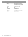
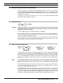
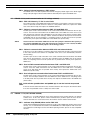
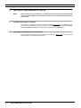
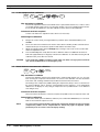
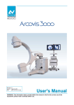
7.3
Cooling curves for x-ray tube
ANODE THERMAL CHARACTERISTICS
210
200
700
180
600
TUBE HOUSING
HEAT DISSIPATION CAPACITY
COOLING
707W
500
140
565W
120
424W
100
80
60
283W
40
141W
0
1
2
3
4
5
6
7
8
TIME (min)
A-10
400
300
200
100
20
0
HEAT STORAGE (kHU)
HEAT STORAGE (kJ)
160
Sophie Mammography X-ray unit
9
10
0
0
50
100
150
200
250
TIME (min)
Technical Manual
Chapter A - GENERAL & TECHNICAL DATA
8
TECHNICAL SPECIFICATIONS (TOSHIBA E7290 X-RAY
TECHNICAL SPECIFICATIONS (TOSHIBA E7290 X-RAY TUBE)
ORIGINAL MANUFACTURER
PLANMED Oy, Asentajankatu 6, 00810 Helsinki, FINLAND
phone: +358-9-7590 5300, fax: +358-9-7590 5555
MODEL AND APPROVALS
MODELS:
APPROVALS:
PLANMED SOPHIE, PLANMED SOPHIE MOBILE
IEC safety class: I, IEC degree of protection: B, IEC enclosure class: IP20
Complies with IEC 601-1 safety and IEC 601-2-7 radiation regulations
X-RAY TUBE ASSEMBLY
X-ray tube
Anode type
Anode braking
Anode thermal capacity
Anode target material
Anode target angle
Tube port material
Focal spot sizes
Filtration
Toshiba E7290
rotating anode (9700 rpm at 180 Hz)
Automatic, electrical
300 000 HU
Molybdenum
16 degrees (large focal spot) / 10 degrees (small focal spot)
Beryllium
0.3mm / 0.1 mm
30µm Mo and 0.5mm Al or
30µm Mo and 25µm Rh
GENERATOR ASSEMBLY
Generator
Anode voltage range
Anode current range/0.3mm focus
Anode current range/0.1mm focus
mAs range/0.3mm focus
mAs range/ 0.1mm focus
Exposure time /0.3mm focus
Exposure time / 0.1mm focus
Cooling
Line voltage
Line voltage compensation
Line voltage regulation
Fuses
Total power consumption
Power factor
Mode of operation
Maximum mains resistance
Maximum continuous
heat dissipation
constant potential, high frequency
20 - 35kV ± 2kV, virtually DC
80 - 110mA ± 5mA
21 - 35mA ± 1mA
10 - 500mAs (optional 600mAs in GB) ± 4mAs
or ±10% (whichever is larger)
10 - 310 mAs
0.1 - 5 seconds (optional 6 seconds) ±5%
0.1 - 9.9 seconds ±5%
automatically controlled (internal fan)
208 - 240V~, 50 or 60Hz - single phase
automatic ±10%
±10% (absolute minimum/maximum 187V~/265V~)
2 x 15AT / 250V
max. 100VA idle, 4000VA max. for 5 seconds
> 0.95
intermittent
≤ 1Ω
< 250W
BUCKY GRID SPECIFICATION
Grid manufacturer
Grid type
Grid movement
Grid ratio
Grid lines per cm
Focusing distance
Application limits
Gilardoni
GRIDGIL HT; Fiber interspaced vertical
Variable amplitude oscillation
r5
N36
f065
18x24: f150 f291
24x30: f153 f282
Material of absorbing strips
Pb
Contrast improvement ratio
K1.47
Selectivity
Σ6.04
Grid exposure factor
B1.69
Transmission of primary radiation Tp 0.75
Max. deviation between the central
line indication and the true
central line
∆2
Technical Manual
Sophie Mammography X-ray unit
A-11
Chapter A - GENERAL & TECHNICAL DATA
TECHNICAL SPECIFICATIONS (TOSHIBA E7290 X-RAY
AUTOMATIC EXPOSURE CONTROL (AEC)
Sensors
Density adjustment
Function modes
three selectable large area solid-state sensors
15 density steps (13% change in OD per step)
plus fine adjustment ± 5 steps (0,05 OD per step)
Normal AEC, Advanced AEC (AAEC)
C-ARM
Rotation
Vertical movement
SID
Compression
Cassette sizes
Magnification
motorized, range -135° to +180°
motorized, range 795mm to 1350mm (31.3in to 53.1in)
650mm
fully motorized, variable speed, variable angle (twincomp)
18 x 24cm and 24 x 30cm
motorized, variable range from 1.3 to 1.8
MECHANICAL DATA
Dimensions
Weight
Color
A-12
Sophie Mammography X-ray unit
(H x D x W) 1000 x 900 x 755 (mm) minimum
(36.6 x 35.0 x 29.7 inch minimum)
160kg (352lbs), unpacked
RAL 9016
Technical Manual
Chapter A - GENERAL & TECHNICAL DATA
USER’S STATEMENT FOR PLANMED SOPHIE (TOSHIBA
9 USER’S STATEMENT FOR PLANMED SOPHIE (TOSHIBA E7290 X-RAY
TUBE)
Radiation leakage technique factors
The maximum-rated peak tube potential is 35 kVp and the maximum rated continuous tube current is 3.5mA for the maximum-rated peak tube voltage.
Minimum filtration
The Beam-limiting device contains three different filtrations 30µm molybdenum, 25µm rhodium
and 0.50mm aluminum. The measured half-value layers are 0.343mmAl, 0.373mmAl and
0.377mmAl at 30kVp. These measured values correspond to aluminum equivalents of 0.55 0.65mmAl.
Rate line voltage
208 - 240V~ ±10%. Line voltage regulation 10%.
Maximum line current
Maximum 22 Amperes at absolute minimum stated mains voltage (187V~)
Technique factors that constitute the maximum line current condition
33kV / 97mA
Generator rating and duty cycle
3.2kW. The duty cycle and wait period can be calculated using the following formulas:
•
Wait period = Tw = kV* mA* exp. Time / 500W
•
Duty Cycle = 1 / (1 + kV* mA / 500W)
Maximum deviation of peak tube potential from indicated value
±2kV
Maximum deviation of tube current from indicated value
±5mA large focal spot, ±1mA small focal spot
Maximum deviation of exposure time tube current product from indicated value
±4mAs or ±10%, whichever is larger
Maximum deviation of exposure time from indicated value
±5%
Definition of measurement criteria
Exposure time
The beginning and end points of the exposure time are defined at 70% of the peak radiation
waveform measured with a calibrated x-ray monitor.
Peak tube potential
Is defined as the measured high voltage mean value measured with a calibrated non-invasive
kVp meter.
Tube current
Is defined using the resistance and voltage over the feedback resistor measured with a calibrated
multimeter. The mA value is then the voltage divided by the resistance.
mAs product
Is defined as the product of the exposure time and the tube current measurements.
Technical Manual
Sophie Mammography X-ray unit
A-13
Chapter A - GENERAL & TECHNICAL DATA
USER’S STATEMENT FOR PLANMED SOPHIE (TOSHIBA
The nominal x-ray voltage together with the highest x-ray tube current obtainable
from the high-voltage generator when operated at its nominal x-ray tube voltage
35kV 91mA - large focal spot
35kV 28mA - small focal spot
The highest x-ray tube current together with the highest x-ray tube voltage obtainable
from the high-voltage generator when operated at its highest x-ray tube current
110mA 29kV - large focal spot
35mA 28kV - small focal spot
The x-ray tube voltage and x-ray tube current which result in the highest electric
output power
33kV 97mA - large focal spot
31kV 32mA - small focal spot
The nominal electric power for a load time of 0.1s and at the nominal x-ray tube
voltage
35kV 91mA - 3185W large focal spot
35kV 28mA 980W small focal spot
Reference current time product
large focal spot: for all kV values
small focal spot: for all kV values
40mA / 0.1s / 4mAs
10mA / 0.1s / 1mAs
The lowest current time product within the specified range of compliance
large focal spot:
small focal spot:
30mA / 0.1s / 3mAs
10mA / 0.1s / 1mAs
The nominal shortest irradiation time in the AEC-mode
20ms
A-14
Sophie Mammography X-ray unit
Technical Manual
Chapter A - GENERAL & TECHNICAL DATA
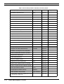
9.1
USER’S STATEMENT FOR PLANMED SOPHIE (TOSHIBA
Toshiba E7290 x-ray tube ratings
Manual exposures
With manual exposures the tube kV and mAs can be selected by the user. In order to keep the
exposure times at minimum the required mAs is always achieved at highest possible tube current
for the kV selected. The parameters are listed in the following table.
Automatic exposures
Automatic exposures are terminated when the radiation detector indicates that the required dose
has been reached. In this mode the kV is selected by the operator and mA is chosen to be the
maximum allowed mA for the selected kV.
If the exposure time is longer than 1 sec (5 sec for the small focal spot) then a falling load technique is used. The exposure is started at the mA as specified in the following table. The accumulated dose is checked at 0.45 sec (2.45 sec for the small focal spot) and if it has reached more
than half of the required dose, the exposure can be continued at the same mA level, and will be
terminated within 1 second (5 seconds for the small focal spot) - well before the tube is overloaded.
If the accumulated dose is detected to be less than half of the required, a longer exposure time
than the one specified for the tube current can be expected. Therefore the tube current is
reduced at this time (after 0.45 or 2.45 sec exposure) to a lower mA that, when added to the
already produced tube loading, will not exceed the maximum tube rating. The falling load current
levels are listed in the following table.
Thermal ratings
Two separate methods are used to protect the tube from overload. One is measuring the tube
head enclosure temperature and if it exceeds 60 °C no further exposures are allowed until it falls
below 60 °C.
The other method keeps the average input power into the tube below or equal to 500W. The
exposure parameters are limited as indicated by the following table, but this feature forces a waiting time between the exposures to ensure that the average power into the tube never can exceed
this limit. For example if an exposure of 24 kV, 100 mAs is performed a wait period of 5 seconds
is calculated and no further exposures are allowed until this time has elapsed.
There is no way to bypass these safety feature under any circumstances, and it is thus virtually
impossible to overload the X-ray tube.
Technical Manual
Sophie Mammography X-ray unit
A-15
Chapter A - GENERAL & TECHNICAL DATA
USER’S STATEMENT FOR PLANMED SOPHIE (TOSHIBA
Table 3: Maximum mA for Tube E7290 vs. different modes
MANUAL EXPOSURE MODE
Large focal spot
(0.3 mm)
AUTOMATIC (AEC) EXPOSURE MODE
Small focal spot
(0.1 mm)
Large focal spot
(0.3 mm)
Small focal spot
(0.1 mm)
kV
0-1
sec.
1-5
sec.
1-6
sec.
0-5
sec.
>5
sec.
0-1
sec.
0.45 - 5
sec.
0.45 - 6
sec.
0-5
sec.
2.45 -10
sec.
20
80
80
80
20
20
80
80
80
20
20
21
84
84
84
21
21
84
84
84
21
21
22
88
88
88
23
23
88
88
88
23
23
23
92
92
92
25
25
92
92
92
25
25
24
96
96
96
27
27
96
96
96
27
27
25
100
100
100
29
29
100
100
100
29
29
26
104
104
104
31
31
104
104
104
31
31
27
108
108
108
33
31
108
108
108
33
30
28
110
110
110
35
30
110
110
110
35
28
29
110
107
104
34
29
110
106
103
34
27
30
110
104
100
33
28
110
103
99
33
26
31
107
101
97
32
27
107
100
96
32
25
32
103
98
93
31
26
103
97
92
31
24
33
100
95
90
30
25
100
94
89
30
23
34
97
92
87
29
24
97
91
86
29
22
35
94
88
84
28
24
94
87
83
28
22
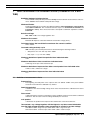
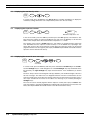
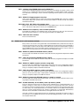
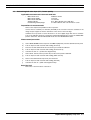
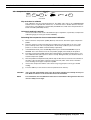
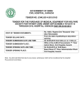
9.2
Cooling curves for x-ray tube
ANODE THERMAL CHARACTERISTICS
210
200
700
180
600
TUBE HOUSING
HEAT DISSIPATION CAPACITY
COOLING
707W
500
140
565W
120
424W
100
80
60
283W
40
141W
0
1
2
3
4
5
6
7
8
TIME (min)
A-16
400
300
200
100
20
0
HEAT STORAGE (kHU)
HEAT STORAGE (kJ)
160
Sophie Mammography X-ray unit
9
10
0
0
50
100
150
200
250
TIME (min)
Technical Manual
Chapter
B
1
UNPACKING & INSTALLATION
PRE-INSTALLATION REQUIREMENTS
Since the SOPHIE is a very small and light-weight unit, the installation can be performed by one
person only. The unit is shipped complete so there is no need to perform special assembly or calibrations on the field. The unit is normally used free-standing, and the mobile version standing on
its own locked wheels, so there’s not normally any need to drill holes during the installation.
1.1
Tools required
Tools for the mechanical installation
A standard set of screwdrivers (a motorized one is recommended for opening the packaging
crate) and millimeter based Allen-keys is about what you need.
Other tools
Please refer to chapter “PREVENTIVE MAINTENANCE CHECKS” on page E-2 for details of test
instruments needed for the installation check-up.
1.2
Environmental requirements
Strength requirement for the floor
The weight of the unit (approx. 160kg) is moderate and does not cause any special requirements
for the strength of the floor.
However, the floor must be straight within 0,5%. The stationary unit has four small feet in the
base that can be adjusted to level the unit if the floor is uneven.
The unit should never be placed on thick carpets for stability and reliability reasons. Antistatic
floor materials should be preferred.
Temperature & Humidity
The operating temperature range is from +15°C to +35°C, non condensing. The acceptable
humidity range is from 25% to 75%. The storage temperature range is from 0°C to +45°C.
NOTE
1.3
If the unit has been stored at temperatures under +10°C for more than a few hours, time
must be allowed for the unit to reach room temperature before turning it on.
Space requirement
Width of door openings
The unit can be transported on its wheels through door openings that are 76 cm wide.
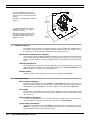
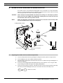
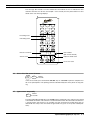
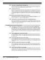
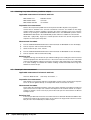
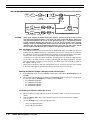
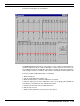
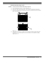
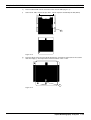
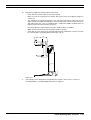
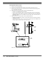
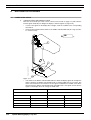
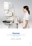
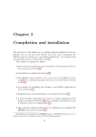
Minimum and recommended Height & Width
The following illustration shows the absolute minimum space requirement of the Sophie unit. The
texts in the following picture indicates the minimum recommended space needed.
Technical Manual
Sophie Mammography X-ray unit B-1
Chapter B - UNPACKING & INSTALLATION
PRE-INSTALLATION REQUIREMENTS
Spreq0198.eps
Recommended minimum clearance
above the C-ARM is 200 mm (8 inch)
when the arm is in the highest possible
position.
This equals a ceiling height of 2190 mm
(84.3 in.)
2190 mm
(84.3 in)
930 mm
(36.6 in)
Recommended minimum clearance
around the unit (left - front - right) is
>900 mm (>35.5 in.).
This equals an operating depth (from
the wall) of 1500 mm (59 in.), and
and operating width (side to side) of
2980 mm (117 in.)
1.4
900 mm
(35.5 in)
1500 mm
(59 in)
Radiation protection
The radiation safety regulations of individual countries must be complied with. Radiation protection devices should be used, as movable or stationary radiation shields. The mobile version of
the Sophie has an integral radiation shield that must be attached to the unit.
Safe distances without specific shielding
A few exposures (without additional radiation shielding) can be made without exceeding the mR/
hour per month limit, if the operator distance is far enough from the unit. Please refer to local regulations. However, protective operator shielding is always recommended, and should always be
used.
Wall LEAD-equivalence
The lead-equivalence of the walls in the room depends on the material used, please refer to local
radiation protection regulations. A recommended safe value of the wall lead equivalence is ≥1
mm and should cover even the most strict requirements.
Movable shields
Radiation shields are also available. Please refer to the “SPARE PARTS MANUAL”.
1.5
Power requirement
Mains voltage & frequency
Nominal operating voltage can be from 208-240 V~, single phase, either between the phases or
between one phase and neutral. The built in line voltage compensation ensures proper operation
within ±10% fluctuation (187-265 V~). The mains frequency can be either 50 or 60 Hz ±10%.
Fuse ratings
The minimum recommended external fuse rating is 15 AT (time-lag). Electromagnetic circuit
breakers can be used, since the unit’s power factor is >0.95. The unit is also protected internally
with 15 AT fuses.
Mains impedance & earthing
To ensure proper operation over the recommended mains voltage range, the resistance of the
mains should not exceed 1 Ω. The unit must be connected to an earthed outlet.
Typical power consumption
The idle power consumption is less that 100VA. The maximum power consumption is worst case
4000VA for a maximum of 5 seconds (Toshiba E7272 tube: at 27kV / 110mA exposure settings,
Toshiba E7290 tube: 33kV / 97mA exposure settings.
B-2
Sophie Mammography X-ray unit
Technical Manual
Chapter B - UNPACKING & INSTALLATION
UNPACKING THE UNIT
2
UNPACKING THE UNIT
2.1
General about unpacking
Unpack the unit indoors in a convenient place, preferably as close as possible to the final installation location. The unit can be transported to the final location on its own wheels. The only limiting factors can be narrow doors or lifts and the fact that you need a mains outlet (208-240VAC)
within 3 meters from the unpacking location. Unpacking the mobile version is similar to what is
described below.
2.2
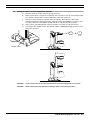
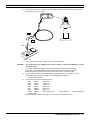
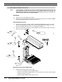
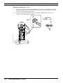
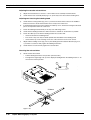
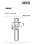
Step-by-step unpacking instructions
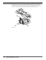
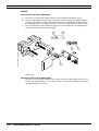
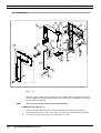
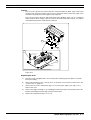
a)
Open and remove the 8 screws on the top of the crate cover. Lift and remove the top cover.
Remove the four large Allen head bolts (item 1). Remove the accessory box from the crate.
b)
Remove the 8 screws (item 2) around the base of the crate and lift the rectangular crate carefully
up and away.
Re
mo
maBe
kefore
of sur un
a e pa
(20tha cki
the
ng
top 8-2t the
an
40
of
cra d
the VA te set
C) is tin
cra
ma wi g
te
ins thi up
firs
n the
t as outle3 me
un
t.
illu
ter it
str
s
ate
d.
SE
EA
PL
ve
TE
O
N
!
FRA
GILE
FRA
GILE
FRA
GILE
Fu
rth
FRA
er
GILE
ins
FRA
GILE
tru
cti
on
s
are
ins
ide
.
FRAGILE
FRAGILE
FRAGILE
FRAGILE
FRAGILE
1
SPAC698.eps
Accessory box
OBL
CC
OBL
LAT
LAT
SIN
DEX
kV
kV
mAs
mAs
CTL
kg
3
2
1
EXP
READY
PRET
Rh
Al
Mo
AAEC
AEC
MAN
3 2 1
CAUTION:
ATTENTION: X-RAYS
RAYONS-X
2
Technical Manual
Sophie Mammography X-ray unit
B-3
Chapter B - UNPACKING & INSTALLATION
UNPACKING THE UNIT
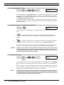
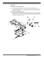
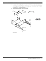
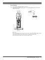
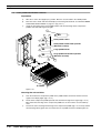
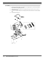
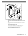
c)
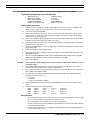
Unpack the transportation handle from the accessories box and install it at the top of the unit, as
illustrated. The screws are already in the handle.
d)
Remove the 3 screws that hold the wooden rear support bar in place (item 3). Remove the eight
screws that hold the wooden front support bars in place (item 4). Remove the support bars and
the rear foam cushion.
Transportation handle
3
OBL
CC
OBL
LAT
LAT
SIN
DEX
kV
kV
mAs
mAs
CTL
kg
3
2
1
EXP
READY
PRET
Rh
Al
Mo
AAEC
AEC
MAN
3 2 1
SPAC598.eps
CAUTION:
ATTENTION: X-RAYS
RAYONS-X
4
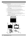
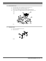
e)
Slide the unit carefully to the rear (by pulling from the handle) until you reach the point of balance.
f)
Carefully let the unit wheels touch the floor and wheel the unit close to the place where it’s going
to be installed or used.
CAUTION
Be careful not to drop the unit when levelling it down to the floor. It’s quite heavy and must
be handled by a strong person(s). It’s always a good idea to use a helping hand or two.
CAUTION
NEVER lift it from the FOOT-PEDALS, C-ARM or HOOD. When handling the unit, lift the
unit from the metal base and/or the transportation handle.
2
Pallet98.eps
1
3
B-4
Sophie Mammography X-ray unit
Technical Manual
Chapter B - UNPACKING & INSTALLATION
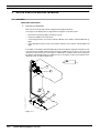
Driving the unit out of the transportation position
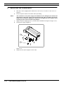
a)
Move the unit to the location where it’s going to be used.
b)
Make sure that there is enough room around the unit so that the C-arm can rotate without hitting
any obstacles. Plug the unit to a mains (208-240V~) outlet and switch it on.
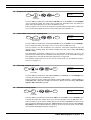
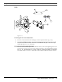
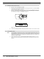
c)
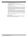
Wait for the unit to perform its self-tests (about 10 seconds). Drive the unit to the normal
operating position by pressing the CTL-key and then pressing and holding the CC-key for three
seconds, or drive the C-arm 300mm upwards with the C-arm/cassette table up switch.
d)
Remove the C-arm locking knob by turning it clockwise. Insert the cover plug to the hole.
e)
The transportation handle can now be removed, and the supplied plastic plugs inserted to cover
the holes in the hood.
onoff98.eps
2.3
UNPACKING THE UNIT
CTL
CC
ON/OFF switch
Technical Manual
trpos98.eps
3 sec
CAUTION
Do not rotate C-arm in its lowest position when the C-arm locking knob is in its place.
CAUTION
Never transport the unit without first driving it down to the transport position.
Sophie Mammography X-ray unit
B-5
Chapter B - UNPACKING & INSTALLATION
2.4
UNPACKING THE UNIT
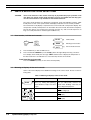
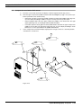
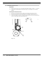
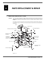
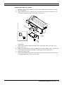
Attaching the unit to the floor
It is recommended to bolt the unit to the floor. The stability of the unit must be checked after
installation.
a)
Turn off the unit and unplug it from the mains.
b)
Remove the base covers, see section “Base covers” on page H-2.
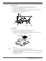
c)
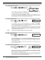
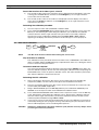
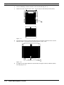
The unit can be bolted either with five (A) or with three screws (B) according to the figure below.
It is recommended to use five screws. Note, that if you are going to use three fastening screws,
move the levelling feet from the front side holes to the rear ones.
A
A
Use either holes labeled A or
holes labeled B.
Fix0198.eps
Rear
B
B
cm
In case you use the holes labelled B,
move the levelling feet from side holes
labelled A to side holes labelled B.
kg
A
A
Front
A/B
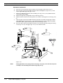
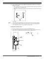
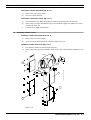
Level the unit if the floor is uneven. The unit has small feet in the fastening holes that can be
adjusted with an Allen key. See figure below.
level.eps
d)
60mm
C-arm locking knob
ø12
Cover strip
Level the unit.
B-6
e)
Use the base as a template and mark the positions of the five/three fastening screw holes to the
floor. Drill the holes (12mm in diameter and 60mm deep) and insert the 12x60 expansion
anchors into the holes.
f)
Fasten the unit to its place with three 8x70 DIN 571 screws. Replace the removed covers.
g)
Remove the C-arm locking knob and attach the cover strip to its position.
Sophie Mammography X-ray unit
Technical Manual
Chapter B - UNPACKING & INSTALLATION
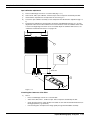
h)
UNPACKING THE UNIT
Check the attachment of the unit. The unit must stay in its position when it is pulled forward as
described below.
•
Drive the C-arm to the uppermost and upright position.
•
Pull the unit forward at the side handles with a force of at least 220 N (22 kg, 50 lbf).
Test98.EPS
160 mm
220N (50lbf)
2.5
Unpacking the accessories
The following minimum set of accessories should be found inside the crate, in every shipped unit:
•
Upper compression paddles (4 pcs):
•
Lower compression paddle 18x24cm
TWINCOMP, Normal, Spot, Biopsy
•
Remote control box and 10m cable (delivered, but optional for the mobile unit)
•
Transportation handle
•
Chin guard
•
Radiation shield (only with the mobile unit model)
•
Rear control panel (only with the mobile unit model)
Unpack carefully the accessories from the boxes found inside the crate. Note that the unit is normally delivered without cassettes.
NOTE
Technical Manual
The small accessories bag is located under the right cover strip of the unit base.
Sophie Mammography X-ray unit
B-7
Chapter B - UNPACKING & INSTALLATION
3
ATTACHMENT OF ACCESSORIES
3.1
Compression paddles
ATTACHMENT OF ACCESSORIES
Please refer to the User’s manual for instructions how to insert the upper compression paddle,
the lower compression paddle or the Bucky device.
3.2
Remote control attachment (optional for the mobile unit)
NOTE
There are two types of the remote control box, the traditional and the extended (that has
an additional READY-light). They unit must be programmed accordingly, depending of
which box is in use. See paragraph “12. Setting type of remote control box” on page F-18
for details.
Attach the remote control box to the rear of the radiation shield to be used, or to any other convenient location that is shielded from radiation. According to local radiation safety regulations, there
must often be a visual contact between the patient and the operator. Please take this into
account when finding a proper location for the remote box.
Connect the remote box to the unit with the supplied cable. It’s NOT recommended to cut the
excess length. The cable should be attached to the walls or put in a cable viaduct, never let the
cable lye on the floor where it can be damaged. Please notice that the remote cable has one
male an one female connector. The male connector is the one that is connected to the unit.
3.3
Mobile Sophie special accessories attachment
The rear control panel and the folding radiation shield must be attached to the unit. Connect the
rear control panel cable to the free connector coming out through the hood and push the excess
of the cable (and the connectors through the hole).
3.4
Exposure warning light (option)
An optional exposure warning light can be connected to the remote box. The light must be powered from an external power source, since the box contains only a circuit breaker relay. See the
schematics for details.
3.5
Printer (option)
To be able to attach a label-printer to the unit, you need an PLANMED manufactured adapter
(please refer to the Spare Parts Manual) to connect to the remote control cable. This adapter is
then connected to the printer with a straight 25-pin RS-232 cable.
3.6
ADMARK darkroom film-marking system
Please refer to the ADMARK manual how to install and use it with the SOPHIE mammographic
unit.
B-8
Sophie Mammography X-ray unit
Technical Manual
Chapter B - UNPACKING & INSTALLATION
4
SETUPS AND CHECKS PRIOR TO USE
SETUPS AND CHECKS PRIOR TO USE
Before using the unit for patient work, some initial setups and checks must be performed. Continue with the setups described in “SPECIAL REGIONAL & INITIAL SETUPS” on page F-1.
Technical Manual
Sophie Mammography X-ray unit
B-9
Chapter B - UNPACKING & INSTALLATION
5
RE-PACKING & TRANSPORTATION OF THE SOPHIE UNIT
5.1
Driving the unit into the transportation position
a)
Make sure that there is enough room around the unit so that the C-arm can rotate without hitting
any obstacles.
b)
Drive the unit to the transport position by pressing the CTL-key and then pressing and holding
the CC-key for four seconds.
CTL
5.2
CC
hold for 3 seconds
c)
If you are going to re-pack the unit, the C-arm locking knob must be inserted to the unit’s base
before driving the unit to the transport position.
d)
After driving the unit to the transport position, drive the C-arm to its lowest position with the Carm/cassette table down -switch.
CAUTION
Do not rotate C-arm in its lowest position after the C-arm locking knob has been inserted
to its place.
Transporting the unit on its own wheels (non-mobile unit)
NOTE
B-10
RE-PACKING & TRANSPORTATION OF THE SOPHIE UNIT
a)
Make sure that the unit is in the transport position.
b)
The transportation handle must be attached, if not, please see paragraph “Step-by-step
unpacking instructions” on page B-3 for details how to attach the handle.
c)
Turn off the unit and unplug it from the mains. Tilt the unit carefully to the rear (by pulling from the
handle) while supporting the base from moving by your foot until you reach the point of balance.
d)
Carefully wheel the unit to the place where it’s going to be re-packed.
Always avoid rough handling, such as running the unit over thresholds at high speed, and
avoid to transport the unit on rough or uneven floors that could cause excessive vibrations in the unit.
Sophie Mammography X-ray unit
Technical Manual
Chapter B - UNPACKING & INSTALLATION
6
MOBILE SOPHIE HANDLING & TRANSPORTATION
MOBILE SOPHIE HANDLING & TRANSPORTATION
The mobile version of the SOPHIE mammographic unit is intended to be easily transported.
However, certain precautions must be followed to guarantee that no harm comes to the unit
when turning the unit into and from the transport position.
CAUTION
Never transport the Sophie Mobile unit without first driving it to the transport position.
Never lift it from the C-ARM or the HOOD. When handling the unit, lift the unit only from
the metal base and/or the transportation handle
NOTE
Make sure that there is enough space around the unit so that the C-arm can freely rotate.
Use the red STOP buttons in case of an emergency.
Classic mobile 180397
Folding radiation shield
Lock
C-arm locking
knob
Unlock
Locking lever
Base front cover plate
Foot control
Locking lever
6.1
Preparing the mobile unit for use after transportation
a)
Lock the transportation wheels by pushing the locking levers down, please see figure above.
b)
Lift the folding top part of the radiation shield into position.
c)
Plug the unit into a appropriate outlet and switch the unit on. A STOP-message should appear on
the time/cm displays.
d)
Turn the C-arm locking knob (located underneath the C-arm) clockwise as far as it goes until it
stops rotating. The STOP-message on the display will disappear.
e)
Lift the foot controls down on the floor, and drive the unit out of the transport position by pressing
the CTL-key and then holding the CC-key for 3 seconds. The unit is now ready for use
CTL
Technical Manual
CC
hold for 3 seconds
Sophie Mammography X-ray unit
B-11
Chapter B - UNPACKING & INSTALLATION
6.2
Preparing the mobile unit for transportation
a)
Make sure that the C-arm locking knob is in its lowest position. Also make sure that the foot
controls are on the floor and not on the base front cover plate.
b)
Drive the unit into the transport position by pressing the CTL-key and then holding the CC-key for
3 seconds.
CTL
B-12
MOBILE SOPHIE HANDLING & TRANSPORTATION
CC
3 sec
c)
Wait until the C-arm movement has stopped and drive the C-arm to its lowest position by
pressing and holding the DOWN-switch.
d)
Turn the C-arm locking knob counterclockwise until it just touches the locking stud. Do not over
tighten the knob since it could bend the C-arm. The STOP-message will now appear on the
displays.
e)
Turn off the power and disconnect the unit from the mains outlet. Place the mains cable on top of
the base so that it cannot fall on the floor during transportation.
f)
Fold down the top part of the radiation shield. Place the foot controls on the base front cover
plate on either side of the C-arm
g)
Pull the locking levers up to release the transportation wheel brakes and the unit is ready for
transportation.
Sophie Mammography X-ray unit
Technical Manual
Chapter
C
1
KEYBOARD FUNCTIONS & MODES
KEYBOARD OVERVIEW
This chapter describes all keyboard functions in a short-form format, and special display modes
in details. For detailed descriptions about adjustments and settings performed with the help of
the keyboards, please refer to chapter “ADJUSTMENT & CALIBRATION” on page F-1.
The unit’s keyboards works in parallel and are identical (see picture below). However, if one of
the keyboards would fail, it is still possible to operate the unit using the other one, since the keyboards operate electronically independently.
hidden
key
Left oblique view key
OBL
CC
OBL
Hidden key
Right oblique view key
Cranio-caudal key
Left lateral key
LAT
LAT
SIN (left breast) key
SIN
DEX
kV
kV
mAs
mAs
Right lateral key
Angle display
DEX (right breast) key
Cassette loading key
kV up/down keys
and display
mAs up/down keys
and display
Density up/down keys
and display
Control (secondary
function) key
Compression release key
CTL
Magnification display
Field/light keys
Magnification key
Time/force display
Sensor indicator lights
3
2
1
EXP
READY
PRET
Rh
Al
Mo
AAEC
AEC
MAN
Automatic/manual
exposure indicator lights
Automatic/manual
exposure key
3 2 1
Exposure/ready
indicator lights
Breast thickness display
kg
CAUTION: X-RAYS
ATTENTION: RAYONS-X
Focal spot indicator lights
Filtration/spot key and indicator lights
Technical Manual
Sophie Mammography X-ray unit C-1
Chapter C - KEYBOARD FUNCTIONS & MODES
USER MODE FUNCTIONS SHORT-FORM
2
USER MODE FUNCTIONS SHORT-FORM
2.1
Normal user functions
The keyboards are always in the normal operating mode when the unit is turned on. Please refer
to the SOPHIE USER’S MANUAL for descriptions for the normal keyboard operation and instructions for normal everyday use of the unit.
2.2
Special user settings
There are some adjustments that the user/operator can perform to set the unit to fulfil individual
needs. The following table is a short-form of these functions. Please refer to the User Manual for
more detailed descriptions.
How to access these special user settings
Press the CTL-key (its LED turns on) and then press the corresponding button. Some of the settings (especially infrequently used ones) require that the corresponding button is held down for
three (3) seconds, preventing inadvertent entry into these modes. Exit from these special user
functions is either automatic or done by pressing again the CTL-key, see details in table below.
Table 10: Special user settings
USER MODE
FUNCTION
AUTOMATIC kV
MODE
AUTOMATIC
RHODIUM/MOLYBDENUM FILTER
SELECTION MODE
DEFAULT
MAGNIFICATION
FACTOR
AUTOMATIC
RELEASE OF
COMPRESSION
INITIAL
COMPRESSION
SPEED
COMPRESSION
SPEED DECREASE
RATE
STOP LIMIT OF
THE
COMPRESSION FORCE
C-2
KEY SEQUENCE
FOR DETAILS, PLEASE REFER TO
“Automatic kV mode” on page F-3
CTL
kV
CTL
CTL
CTL
“Automatic rhodium/molybdenum filter selection mode” on page F-3
CTL
“Default magnification factor” on
page F-4
hold for
2 seconds
CTL
“Automatic release of compression
after exposure” on page F-4
CTL
CTL
mAs
“Initial descent speed” on page F-4
CTL
hold for
3 seconds
CTL
mAs
CTL
“Compression speed decrease rate”
on page F-5
hold for
3 seconds
CTL
LAT
CTL
“Intermediate compression stopping
force” on page F-5
hold for 3 seconds
left LAT key
Sophie Mammography X-ray unit
Technical Manual
Chapter C - KEYBOARD FUNCTIONS & MODES
USER MODE FUNCTIONS SHORT-FORM
Table 10: Special user settings (Continued)
USER MODE
FUNCTION
KEY SEQUENCE
TWINCOMP
COMPRESSION
ON/OFF
CTL
LIFT MOTOR
CRAWLING SPEED
CTL
FOR DETAILS, PLEASE REFER TO
CTL
“Twincomp compression on/off” on
page F-5
hold for
3 seconds
SIN
CTL
“Lift motor
page F-5
crawling
speed”
on
CTL
“Setting correct time and date” on
page F-6
hold for
3 seconds
TIME & DATE
ADJUSTMENT
CTL
3 2 1
TRANSPORT
POSITION
(TO/FROM)
CTL
CC
DENSITY
COMPENSATION
ADJUSTMENT
CTL
AAEC CONTRAST
ADJUSTMENT
CTL
“Transport position” on page C-7
hold for
3 seconds
CTL
“Density
page F-6
offset
adjustment”
on
adjustment”
on
hold for
3 seconds
CTL
“AAEC contrast
page F-6
CTL
“Automatic film labeling (on/off)” on
page F-6
CTL
“Disabling bucky grid movement” on
page F-7
hold for
3 seconds
AUTOMATIC
FILM LABELING
(ON/OFF)
DISABLE
BUCKY GRID
MOVEMENT
ALARM SOUND
FREQUENCY
(loudness)
CTL
LAT
hold for 3 seconds
right LAT key
CTL
hold for
3 seconds
CTL
CTL
hold for
3 seconds
IGNORE
ERRORS
TEMPORARILY
CTL
DIMMING THE DISPLAYS
CTL
DEX
CTL
kV
mA LIMIT
SERVICE MODE
ENTRY
Technical Manual
“Alarm sound frequency (loudness)”
on page F-7
CTL
“Ignore errors
page C-9
hold for
3 seconds
hidden
key
hold for
3 seconds
hold for
3 seconds
hold for
4 seconds
temporarily”
on
“Dimming the displays” on page F-7
“mA limit (on/off)” on page F-7
“How to enter the service mode” on
page F-8
Sophie Mammography X-ray unit
C-3
Chapter C - KEYBOARD FUNCTIONS & MODES
3
SERVICE MODE FUNCTIONS SHORT-FORM
SERVICE MODE FUNCTIONS SHORT-FORM
CAUTION
Some of the functions in the service mode may be jeopardize the proper operation of the
unit. Never use special service mode functions if you are not familiar with how they operate. The service mode is only intended for the trained technician.
The service mode provides easy diagnostics and special setup and calibration functions. Additionally there are also some special control and display modes that are not normally available.
The normal time-of-day display is replaced in the service mode with a temperature display. The
unit operates normally and exposures can be made in the service mode, but with few exceptions.
The unit also ignores user related errors (missing cassettes etc.) and can make exposures as
long as no safety hazards are violated (open feedbacks etc.)
3.1
How to enter / exit the service mode
hidden
key
CTL
press
first
hold for
3 seconds
12:45
kg
Normal mode
Ahhh
kg
Entering service mode...
.
32 C
kg
Service mode entered...
a)
Press the CTL-key so that its LED turns on.
b)
Press and hold the HIDDEN-key for 3 seconds (Above the right oblique view key). The time/
force -display shows briefly the message “Ahhh” and then turns to display the temperature of
the tube head. This is an indication of a successful entry into the service mode.
To exit from the service mode
Press the HIDDEN-key briefly, or turn off the unit temporarily.
3.2
Meaning of displays in the service mode
Some of the normal displays have additional meanings in the service mode. Please see the following table.
Table 11: Meaning of displays in the service mode
DISPLAYS
12:45
kg
0.6
28
110
C-4
kV
mAs
DURING STANDBY
DURING EXPOSURE
Tube head or power supply temperature (°C), waiting time (blinking),
breast thickness, help & error messages
Briefly after the exposure; time difference (in milliseconds) between the
anode motor windings. Used only for
factory diagnostic purposes.
Breast thickness
Actual measured X-ray tube cathode
filament voltage (V)
Selected kV
Actual measured X-ray tube anode
voltage (kV)
Selected mAs
Actual measured X-ray tube anode
current (mA)
Sophie Mammography X-ray unit
Technical Manual
Chapter C - KEYBOARD FUNCTIONS & MODES
3.3
SERVICE MODE FUNCTIONS SHORT-FORM
Service mode settings & special displays
NOTE
Make sure that the unit is in the service mode before performing the functions described
in the following table. Some key sequences might have another meaning if not in the service mode.
Generally special service modes are entered by pressing the CTL-key (so that it’s led turns on)
and the respective key either briefly or by holding it for three (3) seconds, please refer to the
shortform tables. Many of the special service modes require that you exit by pressing the CTLkey. In those modes the CTL-key LED is kept blinking as a reminder to press the CTL-key again
to exit.
The following table is a short-form of all available special service mode keyboard functions. Enter
the service mode first before performing any of the mentioned functions (see page C-4).
Table 12: Service mode keyboard function short-form
SERVICE MODE
FUNCTION
DISPLAYING
INTERNAL
TEMPERATURES
C-ARM UPRIGHT
POSITION
CALIBRATION
BREAST
THICKNESS
MEASUREMENT
CALIBRATION
COMPRESSION
FORCE
MEASUREMENT
CALIBRATION
SPECIAL SYSTEM
PARAMETERS
FOR DETAILS, PLEASE
REFER TO
KEY SEQUENCE IN SERVICE MODE
service
mode
CTL
CTL
service
mode
CTL
CC
“Display of internal temperatures” on page C-7
“C-arm upright position
calibration” on page F-12
CTL
hold for
3 seconds
service
mode
“Breast thickness measurement calibration” on
page F-12
CTL
hold for
3 seconds
service
mode
CTL
15kg
LAT
CTL
hold for 3 seconds
left LAT key
service
mode
CTL
CTL
mAs
“Compression force measurement calibration” on
page F-13
“Special system parameters setup” on page F-17
hold for
3 seconds
X-RAY TUBE
FILAMENT
VOLTAGE
CALIBRATION
service
mode
“X- ray tube filament preheating voltage calibration”
on page F-14
CTL
hold for
3 seconds
tube type
C
mAs
A
EXP
large focus bias setting
hold until
finished
kV
small focus bias setting
CTL
exit without
programming
Technical Manual
Sophie Mammography X-ray unit
C-5
Chapter C - KEYBOARD FUNCTIONS & MODES
SERVICE MODE FUNCTIONS SHORT-FORM
Table 12: Service mode keyboard function short-form (Continued)
SERVICE MODE
FUNCTION
AEC-SENSOR
CALIBRATION
service
mode
CTL
3 2 1
hold for
3 seconds
DISPLAY OF REAL
DENSITY VALUE
EXPOSURE
COUNTER
DISPLAY
DIAGNOSTIC
DISPLAY OF
INTERNAL SIGNALS
DISPLAY RECENT
49 ERROR MESSAGES
PRINT RECENT 49
ERROR MESSAGES
kV-VALUE FINEADJUSTMENT
FOR DETAILS, PLEASE
REFER TO
KEY SEQUENCE IN SERVICE MODE
service
mode
CTL
service
mode
CTL
service
mode
CTL
phantom
CTL
EXP
hold until
finished
mAs
CTL
“Displaying the real density
value” on page C-8
CTL
“Displaying the exposure
counter” on page C-8
“Diagnostic display of
internal signals” on
page C-10
CTL
hold for
3 seconds
service
mode
CTL
OBL
CTL
hold for 3 seconds
left OBL key
service
mode
OBL
service
mode
CTL
“Displaying the recent 49
error messages” on
page C-8
“Print a list of the recent 49
errors” on page C-9
hold for 3 seconds
left OBL key
kV
“AEC-sensor calibration”
on page F-15
“kV-value fine-adjustment”
on page F-16
hold for
3 seconds
kV
CTL
mAs
C-6
Sophie Mammography X-ray unit
Technical Manual
Chapter C - KEYBOARD FUNCTIONS & MODES
4
SERVICE MODE FUNCTION DETAILS
SERVICE MODE FUNCTION DETAILS
The following pages in this chapter contains detailed descriptions of all service mode keyboard
functions, except for all adjustment and setup functions. Please refer to “KEYBOARD-CONTROLLED (in service mode)” on page F-8 for details how to perform setups and calibrations controlled in the service mode.
A shortform of all service mode functions can be found in the paragraph “SERVICE MODE
FUNCTIONS SHORT-FORM” on page C-4.
4.1
Transport position
CC
CTL
CAUTION
hold for
3 seconds
Ensure that there is free space around the unit so that the C-arm doesn’t hit any obstacles
during the movement. To stop the C-arm in an emergency situation, press either any of the
STOP-buttons or the foot controls.
Press the CTL-key and press and hold the CC-key for 3 seconds.
This key sequence drives the unit either to the transport position or back to normal upright position. After driving the unit to the transport position, drive the C-arm to its lowest position by pressing the C-arm height adjusting down -switch.
The unit should never be transported when not in the transport position. In the transport position
the unit runs the C-arm as low as possible and turns the tube-head against the floor. This
ensures that the center point of gravity is as low as possible.
4.2
Display of internal temperatures
service
mode
CTL
CTL
.
32 C
TUBE HEAD
temperature
kg
41 .CP
kg
POWER SUPPLY
temperature
Press the CTL-key when in the service mode to toggle between the two different internal temperature displays. The temperature of the TUBE HEAD housing is shown in the time/force display
when the CTL-key led is off (the display shows the temperature in degrees Celsius). The temperature of the POWER SUPPLY heatsink is shown when the CTL-key led is on (the display shows
the temperature in degrees Celsius and the “P”-letter as an indication of “P”ower supply temperature).
NOTE
This temperature display has the lowest priority. It could be sometimes replaced by other
more important displays in the service mode, such as magnification ratio, waiting time
etc.
The TUBE HEAD temperature slowly increases about 10°C to 15°C above the ambient temperature, even if the unit stands idle. This is fully normal since the POWER SUPPLY is using the
housing of the TUBE HEAD as it’s heatsink.
The POWER SUPPLY heatsink temperature slowly increases about 10°C to 15°C above the
TUBE HEAD temperature even if the unit stands idle. This is fully normal since the thermal contact from the power supply to the TUBEHEAD is not ideal, but fully sufficient for effective cooling
of the power supply. If the temperature of the POWER SUPPLY heatsink increases more than
mentioned, it could indicate that the power supply is not properly tightened into its place.
Technical Manual
Sophie Mammography X-ray unit
C-7
Chapter C - KEYBOARD FUNCTIONS & MODES
4.3
SERVICE MODE FUNCTION DETAILS
Displaying the real density value
service
mode
CTL
CTL
In service mode, press the CTL-key, the density up -key and then the CTL-key to display the
real density setting, without the zero compensation (can be set in the user mode).
4.4
Displaying the exposure counter
service
mode
mAs
CTL
1437
CTL
kg
Number of exposures / 10
In the service mode, press the CTL-key and then press the mAs up -key. The time/force -displays shows the number of exposures divided by ten (10). Press the CTL-key to exit from this
mode. In the example above the actual number of exposures is c. 14.370.
The capacity of the counter is 50.000 exposures, after which it is cleared and starts again from
zero. Remember that the exposure counter memory is on the REAR CPU, replacing it also
means that you loose the current exposure counter data. The exposure counter can be cleared
(together with the error message list), but only by PLANMED. Spare REAR CPU boards have the
exposure counter cleared at the factory.
4.5
Displaying the recent 49 error messages
service
mode
CTL
OBL
CTL
hold for
3 seconds
In service mode, press the CTL-key and then press and hold the left OBL key for 3 seconds.
Use the field/light -keys to scroll through the list. The left field/light -key steps backwards in the
list (and time), the right field/light -key steps forward in the list. Press the CTL-key to exit this
mode.
The list is always shown in chronological order (by date/time). The maximum length of the list is
49 error messages. The oldest ones are dropped off the list if the list is full and there are new
errors that needs to be stored. The list is shorter if there are less than 49 error messages store. It
also wraps around from the newest to the oldest error message if you continue pressing the
field/light -keys.
The error list can be cleared (together with the exposure counter) but only by PLANMED. The
error message list is stored on the REAR CPU, replacing this also means that you loose the error
history data. Spare REAR CPU boards have the error list cleared at the factory.
C-8
Sophie Mammography X-ray unit
Technical Manual
Chapter C - KEYBOARD FUNCTIONS & MODES
SERVICE MODE FUNCTION DETAILS
The message “EE” instead of an error number does not indicate an error. It indicates the date
and time when the error list was erased (EE = errors erased). See the picture below for more
details of the error message displays.
OBL
CC
OBL
LAT
LAT
IN
S
X
E
D
kV-setting used
kV
kV
mA-setting used
mAs
mAs
CTL
Date of occurrence
Error number
(EE = Errors Erased)
kg
3
2
1
Sensor used
P
X
E
A
E
RY
D
PR
T
E
R
h
Al
M
o
AAE
C
AE
C
A
MN
Exposure mode used
3 2 1
CAU
TION
:X
-R
AY
S
ATTE
TIO:NR
N
AY
ON
-X
S
4.6
Focus size used
Print a list of the recent 49 errors
service
mode
OBL
hold for
3 seconds
In the service mode, press and hold the left OBL -key for 3 seconds to print the complete error
list on an optional printer. The printing cannot be aborted. Briefly turn off the printer to stop printing.
4.7
Ignore errors temporarily
CTL
hold for
3 seconds
Pressing and holding the CTL-key for 3 seconds ignores temporarily error codes that are related
to motorized movements. This function is useful in situations when the unit needs to be driven to
a certain position, but because of an possible error this would not be possible Error that are
related with the safety of the unit cannot be ignored this way (such as X-ray tube related problems).
Technical Manual
Sophie Mammography X-ray unit
C-9
Chapter C - KEYBOARD FUNCTIONS & MODES
4.8
SERVICE MODE FUNCTION DETAILS
Diagnostic display of internal signals
service
mode
nn.
CTL
CTL
hold for
3 seconds
kg
nn = display mode number
segments on the right side of the decimal
point indicates the sensor(s) signals(s)
In the service mode, press the CTL-key and then press and hold the field/light up -key for 3
seconds. Use the density-keys to step to the desired mode, please refer to the details below.
Press the CTL-key to exit from this special display mode.
In this display mode it is possible to monitor the signals from virtually all sensors and switches,
reaching both the REAR and TUBE CPUs. Additionally, if the sensor(s) selected are related with
a motorized function, it is possible to control the related motor with the help of the field/light
keys.
CAUTION
During this mode the sensors that normally operate as limit sensors are displayed but otherwise fully ignored. It is thus possible to drive the respective mechanism past the normal
operating range to the mechanical end. Use this feature with care and avoid overloading
the mechanisms.
00. Mirror mechanism Hall-sensor signal & motor drive
00.
right middle segment = magnet at sensor (mirror out of the Xray beam)
01. Filter mechanism Hall-sensor signal & motor drive
01.
right middle segment = magnet at sensor (filter at position 1 [Mo])
02. Collimator mechanism Hall-sensor signal & motor drive
02.
right middle segment = magnet at sensor (collimator at widest field)
03. Labeling disc Hall-sensor signal & motor drive
03.
right middle segment = magnet at sensor
04. MAG/LOAD mechanism Hall-sensor signals& motor drive
04.
right upper segment = contact view position sensor
left middle segment = motor rotation sensor signal
right lower segment = maximum magnification position sensor
05. UP/DOWN mechanism Hall-sensor signals & motor drive
05.
C-10
Sophie Mammography X-ray unit
right upper segment = at highest position
right middle segment = lift reference sensor signal
right lower segment = at lowest position
left middle segment = motor rotation sensor signal
Technical Manual
Chapter C - KEYBOARD FUNCTIONS & MODES
SERVICE MODE FUNCTION DETAILS
06. C-arm mechanism and rotation reference sensor signals & motor drive
06.
right upper segment = arm position to extreme left (-135°)
left middle segment = motor rotation sensor signal
right middle segment = arm rotation reference sensor signal (±10°)
right lower segment = arm position to extreme down (180°)
07. Compression mechanism sensors Hall-sensor signals & motor drive
07.
right upper segment =at highest (TWINCOMP release) position
right middle segment = at upper position
right lower segment = at lowest position (full compression)
08. Cassette table size and cassette in place sensor switch signals
08.
right upper segment = large cassette position switch signal
right middle segment = cassette detector switch signal
right lower segment =small cassette position switch signal
09. Lower compression paddle size sensor switch signals
09.
no segments = no paddle inserted
left lower segment =small paddle (left switch)
right lower segment = large paddle (right switch)
both lower segments = paddle tilted upwards
10. Cassette table control switch signals
10.
left upper segment = C-arm counterclockwise signal (upper right side switch)
right upper segment = drive unit up switch signal
right lower segment =drive unit down switch signal
left lower segment = C-arm clockwise signal (lower right side switch)
Note, that the operation of the left side C-arm rotation switches is opposite of the operation of the
right side switches.
11. Foot pedal switch signals
11.
left upper segment =left pedal outer edge switch signal
right upper segment = right pedal outer edge switch signal
right lower segment = right pedal inner edge switch signal
left lower segment = left pedal inner edge switch signal
12. Bucky & Stereotactic identification signal
12. n
n = 0; no Bucky grid or Stereotactic system connected
n = 1; Bucky grid connected
n = 2; Stereotactic system connected, no needle inserted
n = 3; Stereotactic system connected, needle inserted
n = 4-6; Bucky grid connected
13. Bucky & Stereotactic internal sensor signals
13.
left upper segment = Bucky grid sensor or Stereotactic pulse sensor 1
right upper segment = Stereotactic pulse sensor 2
right lower segment = right side Stereotactic position sensor
left lower segment = left side Stereotactic position sensor
14. Exposure switch signal
EXP
14.
vertical segment =exposure switch signal
15. Keyboard & Lamp test
15.nn
nn = matrix keyboard scan code
All LEDs should be lit on panels when you press the automaic/manual exposure key.
Technical Manual
Sophie Mammography X-ray unit
C-11
Chapter C - KEYBOARD FUNCTIONS & MODES
SERVICE MODE FUNCTION DETAILS
16. Compression force sensor output
16.nn
nn = hexadecimal value of the compression force sensor signal
This display shows (as a hexadecimal number) the compression force sensor output (used for
internal factory tests only).
17. Tube temperature sensor output
17.nn
nn = hexadecimal value of the tubehead temperature sensor signal
This display shows (as a hexadecimal number) the tube temperature sensor output (used for
internal factory tests only).
18. Power supply temperature sensor output
18.nn
nn = hexadecimal value of the power supply temperature sensor signal
This display shows (as a hexadecimal number) the power supply temperature sensor output
(used for internal factory tests only).
C-12
Sophie Mammography X-ray unit
Technical Manual
Chapter
D
1
HELP AND ERROR MESSAGES
GENERAL ABOUT ERROR DISPLAYS
The microprocessor system in the SOPHIE is capable of reporting about various abnormal conditions. There are three different message types that can appear on the clock displays; STOP,
HELP and ERROR.
The STOP and HELP displays are mainly intended to guide the user in everyday use of the unit.
The ERROR system is intended as an aid for the service technician in case of faults or abnormal
conditions. The last 49 ERROR events are stored in internal memory and can be retrieved and
viewed on demand (or printed if a suitable printer is connected), see paragraph “Printer (option)”
on page B-8 for details.
1.1
Stop-message
St 0P
kg
The STOP message indicates that one or several of the red emergency STOP-buttons are activated. No motorized movements or exposures are possible during this condition. Release (pull
upwards) both STOP-buttons in the foot controls to clear this situation. If the STOP cannot be
cleared from the displays, turn the unit off momentarily, and if the STOP-message still appears,
please check the condition of the STOP button switches
1.2
Help messages
HE nn
kg
The HELP message (nn= any two digit number) is shown on the clock display as long a key that
has no function is pressed, or if the function is not allowed. The help display disappears automatically when the key that caused it is released. Please refer to paragraph “HELP MESSAGES
SHORTFORM TABLE” on page D-2 for details about help codes. HELP messages 0 to 9 have
the same meaning as the respective ERROR codes. For flexibility, many of the HELP-messages
are NOT shown when the unit is in the SERVICE-mode. If the unit is reporting help messages not
found in this manual, please contact your Planmed dealer for a newer revision of the Technical
Manual.
1.3
Error messages
Er nn
kg
The ERROR message (nn= any two digit number) appears on the clock display if a fault or
abnormal condition is detected. The error must be cleared from the display with the CTL-key,
before you can continue to use the unit. The last 49 occurrences are stored in internal memory,
from where it’s possible to check the unit’s error history. The date, time and also exposure
parameters are stored together with the error codes to improve the diagnostic value of the error
memory. Some of the ERROR messages (0 to 9) as well as STOP and HELP messages are not
stored in the list, since they are not categorized as a device malfunction. Please see the detailed
error description list for details. If the unit is reporting error messages not found in this manual,
please contact your Planmed dealer for a never revision of the Technical Manual.
Technical Manual
Sophie Mammography X-ray unit D-1
Chapter D - HELP AND ERROR MESSAGES
2
HELP MESSAGES SHORTFORM TABLE
HELP MESSAGES SHORTFORM TABLE
The following is a list of all currently available HELP messages. These messages appear on the
TIME/FORCE-display if a key without any function is pressed, or if the function is not allowed for
some reason. The HELP message disappears automatically when the key is released. Help
messages in the range from 1 to 9 have the same meaning than the respective error codes.
Table 13: Help messages shortform table
HE
REASON
ACTION
HE 1
Magnification is not allowed with a Bucky grid
Remove the Bucky grid first
HE 2
Bucky is not correctly positioned or properly inserted Check that the guide pins are firmly inserted
into the unit
HE 4
The cassette is not properly positioned into the Push the cassette against the labeling head
holder
HE 5
The cassette has not been removed since the previ- Remove and reload with a fresh film (double expoous exposure
sure prevention warning)
HE 6
The cassette table is in an undefined position
HE 7
A large cassette with a small lower paddle is not Either change to a small cassette or a large lower
allowed because the lower compression paddle compression paddle
would collide with the cassette
HE 8
A small cassette with a large lower paddle is not Either change to a large cassette or a small lower
allowed because the film labeling head would collide compression paddle
with the compression paddle
HE 9
No projection angle is selected
HE10
The lower compression paddle has risen too far Remove any obstructing objects and check that the
upwards
cassette and lower paddle are firmly inserted
HE11
The Up/Down movement of the unit is not allowed Release the paddle before driving the unit, or turn off
during the compression of the breast
this safety feature in the service mode
HE13
The Aluminum filter (filter no 2) is not allowed with Increase the kV-setting if you wish to use the AlumikV-settings lower than 30 kV
num filter
HE14
The kV-setting cannot be changed before you either Reduce the mAs setting first
reduce the mAs-setting
HE18
A higher mAs-value is not allowed with the current Decrease the kV-setting first
kV-setting
HE20
This key functions only during AEC-mode
HE21
This key functions only in the manual exposure mode Select manual mode first with the AEC-key
HE23
This key has no function in together with the CTL-key Press the CTL-key to turn its indicator off
HE24
The C-arm cannot be rotated with the C-arm rotation Select the exposure view or decrease the compresswitches, either the exposure view is not selected or sion force.
the compressive force is more than 5 kg.
HE25
The error must be cleared first from the display
HE26
This key has no function in the STEREOTACTIC- Remove the STEREOTACTIC system first
mode (ex. SIN, ML, LOAD etc.)
HE27
The exposure switch is still activated
HE28
The C-arm is not allowed to continue to rotate with- Press and hold any of the foot controls to continue
out pressing any of the foot controls
the movement of the C-arm
D-2
Sophie Mammography X-ray unit
Fully push or pull the labeling head to either end
Use the LM, MLO or CC-key for projection selection
Select the AEC-mode first with the AEC-key
Press the CTL-key
Release the exposure switch in the remote control
Technical Manual
Chapter D - HELP AND ERROR MESSAGES
HELP MESSAGES SHORTFORM TABLE
Table 13: Help messages shortform table (Continued)
HE
REASON
HE29
You cannot proceed because the cassette table is in Press the LOAD-key
the LOAD- position
HE30
The UP/Down movement or change of projection is Remove needle before repositioning the unit
not allowed in the STEREO-mode with the needle
inserted
HE31
Use the REL-key to drive the STEREO- device
HE33
LOAD and MAG positions are not allowed when Press either MAG- or LOAD-key to drive back to conusing the STEREOTACTIC-system
tact view position
HE34
The C-arm is not allowed to continue to rotate with- Press and hold down any of the foot-controls, otherout pressing any of the foot controls in the STEREO- wise the C-ARM will not rotate. The patient may
TACTIC mode
remain in position
HE35
You can not select the Automatic paddle release
HE36
You have to release the upper compression paddle Press and hold down the REL-key until the upper
before selecting the exposure view
compression paddle has reached its highest position
HE37
The bucky grid is not connected.
HE39
The AAEC mode is not allowed with current kV-set- Increase the kV-setting first if you wish to use AAEC.
ting. OR
A lower kV-setting is not allowed with the AAEC.
HE40
The advanced AEC mode can not be used with the Select the molybdenum filter.
aluminium filter.
Technical Manual
ACTION
Connect the bucky grid.
Sophie Mammography X-ray unit
D-3
Chapter D - HELP AND ERROR MESSAGES
3
ERROR MESSAGES SHORTFORM TABLE
ERROR MESSAGES SHORTFORM TABLE
The following is a list of all currently available error messages. For a detailed discussion about
fault finding, please refer to paragraph “TROUBLESHOOTING & FAULTFINDING” on page G-1.
NOTE
Error messages marked with an asterisk (*) are not stored in the internal error list. These
error share the same meaning as the respective HELP messages
Table 14: Error Codes Short Form Table
Er
ERROR MESSAGE EXPLANATIONS
Er00*
Exposure switch was released too early during the exposure
Er01*
Magnification exposures cannot be taken with the Bucky connected. Remove the Bucky grid.
Er02*
Bucky is not correctly positioned or the paddle size sensing microswitch signal is wrong
Er03*
There signal from the selected AEC-sensor is too low or missing completely, or the radiation reaching the
sensor is extremely low or missing completely, or the small focus is accidentally selected (instead of normal)
Er04*
The cassette is not properly positioned on the cassette table, or a problem with the cassette sensing switch
Er05*
The cassette was not removed from the unit after the last exposure (double exposure prevention)
Er06*
The cassette guides are not positioned firmly against the sides of the cassette, or a problem with the cassette
size sensing switches
Er07*
A large cassette with a small lower paddle is not allowed, or a problem with the size sensing switches
Er08*
A small cassette with a large lower paddle is not allowed, or a problem with the size sensing switches
Er09*
Exposure is not allowed before you select a projection, or the cassette table is in the LOAD-position
Er10
X-ray tube Anode voltage (kV) overshoot
Er11
X-ray tube Anode voltage (kV) dropped suddenly
Er12
X-ray tube cathode filament pre-heating voltages are not calibrated
Er13
X-ray tube Anode current (mA) sudden peak (possible X-ray tube arching)
Er14
AEC-sensor(s) are not calibrated
Er15
Failure in the currently selected AEC-sensor (occurs mainly during calibration of the AEC-sensor)
Er16
AEC-sensor feedback signal open circuit failure
Er17
Bias values for normal and small focus are not selected
Er18
kV fine-adjustment parameter values in TUBE CPU differ from the values in REAR CPU
Er20
Mirror motor time-out. The mirror mechanism doesn’t reach the limit sensor within a specified time
Er21
Filter motor time-out. The filter mechanism doesn’t reach the limit sensor within a specified time
Er22
Collimator motor time-out. The collimator mechanism doesn’t reach the limit sensor within a specified time.
OR
Cutter motor time-out. The cutter mechanism doesn’t reach the sensor within a specified time.
Er23
Labeling motor time-out. Labeling disc magnet does not pass the reference sensor within specified time
Er24
Bucky grid motor time-out. The grid does not move or there is no signal from sensor within a specified time
Er25
MAG/LOAD motor error. No pulses from motor even if the motor is driven.
Er26
X-ray tube anode doesn’t rotate properly, or a problem in the anode motor rotation sensing
D-4
Sophie Mammography X-ray unit
Technical Manual
Chapter D - HELP AND ERROR MESSAGES
ERROR MESSAGES SHORTFORM TABLE
Table 14: Error Codes Short Form Table (Continued)
Er
ERROR MESSAGE EXPLANATIONS
Er27
Compression motor time-out. The mechanism doesn’t reach the limit sensor within a specified time
Er28
Compression force measurement calibration failure, force signal out of range
Er29
Membrane keyboard key short-circuited/pressed or faulty display board during the self test
Er30
X-ray tube Anode voltage (kV) missing, dropping during exposure or lower that the setting
Er31
X-ray tube Anode current (mA) missing, dropping during exposure or lower than the setting
Er32
X-ray tube Anode current (mA) higher than the setting
Er33
X-ray tube Filament voltage (V) missing, or outside the required (too low or too high)
Er34
X-ray tube Bias voltage (V) power supply circuitry failure
Er35
The Mains-sync signal from the SYNC PCB is not reaching the TUBE-CPU
Er36
The REAR CPU detected a too long exposure (>10sec) and terminated it
Er37
kV feedback signal open circuit
Er38
mA feedback signal open circuit
Er39
Cassette table key failure or pressed during self test
Er40
Lower compression paddle not firmly inserted or lifted up by something obstructing it, or problem with the
lower compression paddle size identification switches
Er41
C-arm angle-, Lift mechanism height-, or Compression paddle positional information was wrong
Er42
Spurious pulses from C-arm motor rotation sensor, or the motor rotates even if not commanded
Er43
No pulses from C-arm rotation motor rotation sensor, or motor does not rotate even if commanded
Er44
MAG-motor is rotating even if not commanded, or spurious pulses from MAG-motor rotation sensor
Er45
Lift- motor is rotating even if not commanded, or spurious pulses from Lift-motor rotation sensor
Er46
No pulses from Lift-motor rotation detector, or motor does not rotate even if commanded
Er47
Mains frequency out of range (45...65 Hz) or failure in frequency measurement circuitry
Er48
Failure in the STEREOTACTIC-device stepper motor or its control circuitry or in the rotation sensors
Er49
The STEREOTACTIC-device shelf is not at the end position sensor, or a failure in the sensor
Er50
Tube head assembly temperature sensor short circuit
Er51
Tube head assembly temperature sensor open circuit
Er52
Filament voltage feedback open circuit
Er53
Power supply heatsink temperature sensor short circuit
Er54
Power supply heatsink temperature sensor open circuit
Er55
C-arm rotation reference sensor failure
Er56
Compression mechanism release limit sensor failure during calibration
Er57
Exposure switch failure (short circuit) or pressed during self test
Er58
Foot control switch failure (short circuit) or pressed during self test
Er59
Failure in internal emergency STOP-system
Technical Manual
Sophie Mammography X-ray unit
D-5
Chapter D - HELP AND ERROR MESSAGES
ERROR MESSAGES SHORTFORM TABLE
Table 14: Error Codes Short Form Table (Continued)
Er
ERROR MESSAGE EXPLANATIONS
Er60
TUBE CPU internal ± 15VDC voltage is out of limits
Er61
Failure or sporadic disturbance in serial communication between TUBE- and REAR-CPU or non compatible
software versions
Er62
Failure or sporadic disturbance in serial communication between REAR CPU and external test device
Er63
Error in STOP communication line between TUBE- and REAR-CPU
Er64
Error in exposure communication line between TUBE- and REAR-CPU
Er68
Both switches (paddle down and paddle up) of one foot control are pressed down.
Er71
Software chip (EPROM) failure on TUBE CPU
Er72
Software chip (EPROM) failure on REAR CPU
Er73
REAR CPU attempted to execute an illegal program instruction
Er74
REAR CPU watchdog reset occurred (please contact Planmed)
Er75
REAR CPU illegal interrupt detected (please contact Planmed)
Er76
REAR CPU timer interrupt error (please contact Planmed)
Er77
REAR CPU stack overflow (please contact Planmed)
Er78
Time-of-day clock oscillator (32768 Hz) not oscillating or out of tolerance
Er79
TUBE-CPU stack overflow (please contact Planmed)
Er80
REAR CPU parameter memory (EEPROM) failure
Er81
TUBE CPU parameter memory (EEPROM) failure
Er82
REAR CPU CONFIG-register contains wrong data
Er83
TUBE CPU CONFIG-register contains wrong data
Er84
REAR CPU parameter memory (EEPROM) is empty or erased
Er85
Flat battery on REAR CPU (RAM stand-by NiCad battery is drained or has failed)
Er86
Short mains voltage abruption or drop was detected, or error in detection circuitry
Er87
Illegal country code or country code not set
Er 88
Battery back-up memory (RAM) is erased
Er 89
Wrong type C-ram rotation motor sensor in the EEPROM memory
Er90
Wrong type of rotation motor rotation sensor (must be a HEDS-type sensor if Stereotactic system is used)
Er91
Error in the STEREOTACTIC-sensor system (both end limit sensors are on simultaneously)
Er92
Error in the MAG/LOAD movement sensor system (simultaneous signals from both end limit sensors)
Er93
Error in the compression system end limit sensors (simultaneous signals from both end limit sensors)
Er94
Error in the C-arm rotation sensor system (simultaneous signals from the reference and/or limit sensors)
Er95
Error in the lift mechanism sensor system (simultaneous signals from both end limit sensors)
Er96
Error in the Bucky mechanism or in the sensor or in the movement of the mechanism. (This error is NOT displayed, but is stored in the error list)
D-6
Sophie Mammography X-ray unit
Technical Manual
Chapter D - HELP AND ERROR MESSAGES
ERROR MESSAGES SHORTFORM TABLE
Table 14: Error Codes Short Form Table (Continued)
Er
ERROR MESSAGE EXPLANATIONS
Er97
No pulses from the MAG/LOAD motor rotation sensor, or the motor does not rotate even if commanded
Technical Manual
Sophie Mammography X-ray unit
D-7
Chapter D - HELP AND ERROR MESSAGES
4
DETAILED ERROR MESSAGE EXPLANATIONS
DETAILED ERROR MESSAGE EXPLANATIONS
The purpose of the error messages is to make faultfinding easier. The internal list of the last 49
error occurrences is of a great help since it contains additional information, such as time, date
and other exposure parameters and settings when the error occurred. Please refer to paragraph
“SERVICE MODE FUNCTIONS SHORT-FORM” on page C-4 how to display (or print) the error
list. This chapter discusses in greater detail the errors and gives background information about
reasons for the errors. If you need further assistance with faultfinding, please refer to paragraph
“TROUBLESHOOTING & FAULTFINDING” on page G-1.
4.1
ERRORS 00-09 (User related, not stored in internal error list)
These errors usually indicate that some external circumstance causes a situation where the unit
refuses to continue with the exposure. These errors can easily be corrected by the user. However, some of these errors could be caused by a malfunctioning sensor, cable or switch and the
following explanations should help in detecting the problem.
ER00 - Exposure switch was released too early during exposure
The most probable cause (if the switch really was pressed firmly during the whole exposure) is a
bad exposure switch or faulty spiral cable, or interconnection cable. The signal from the switch
can be viewed in the service mode for easier faultfinding. The signal goes from the switch to the
remote control box, and from here to the BASE PCB and REAR CPU.
ER01 - Magnification is not possible with Bucky installed
Remove the Bucky cable plug from the connector under the cassette table. If this error appears
even with no Bucky connected, there is a problem in indentifying if the Bucky is connected or not.
The identifying signal can be monitored in the service mode for easier faultfinding. The Bucky
signals goes to the TUBE CPU. Check the wiring and as a last remedy, change the TUBE CPU.
ER02 - Bucky is not inserted but cable is connected
If the Bucky grid is inserted with the attaching pins all the way down into the holes, and the error
still occurs, then there is a problem in identifying the compression paddle through the rear fingers. There are two microswitches (one inside each pin hole) identifying the paddle size and
existence. Check the operation of these switches, their signals can be viewed in the service
mode for easier faultfinding. There could be a bad microswitch or a faulty cable or connector. The
signals from these switches goes through the FRONT COLLECTOR PCB and REAR COLLECTOR PCB boards to the REAR CPU.
ER03 - No or too low signal from the AEC-sensor
The TUBE CPU doesn’t get any signal from the AEC SENSOR PCB during the exposure or very
little radiation is reaching the selected sensor. Check first if there are any foreign objects
obstructing the beam. Check that the small focus has not been accidentally selected instead of
the normal size one. Check if the other two sensors give the same error. If not, then the AEC
sensor assembly must be replaced. If the tube is really producing a beam that reaches the sensor (check with a fluorescent screen) and this error still occurs it is an indication that the AEC
sensor signal is not reaching the TUBE CPU. Probably the AEC-sensor PCB produces a signal
but there is a break or bad contact somewhere. Check the wiring from the sensor to the TUBE
CPU. Change the AEC-sensor assembly. The last one to change is the TUBE CPU or POWER
SUPPLY.
ER04 - The cassette is not properly positioned
The cassette rear edge is not touching the labeling head assembly front edge where the sensing
button is located. If the button is pressed and the error still repeats, then there is a problem with
the sensing microswitch or its cabling. Check that the microswitch is not mechanically damaged
or obstructed. The switch signal can be monitored in the service mode for easier faultfinding.
Check the wiring starting from inside the labeling device. The signal goes from the switch through
the LABELING PCB and SHELF COLLECTOR PCB to the TUBE CPU. Change the TUBE CPU
as last remedy.
D-8
Sophie Mammography X-ray unit
Technical Manual
Chapter D - HELP AND ERROR MESSAGES
DETAILED ERROR MESSAGE EXPLANATIONS
ER05 - Cassette was not removed since the previous exposure
If the cassette was removed but this error still appears, perform the same checks as in ER04.
ER06 - The cassette table edges are not firmly against the cassette side
There are two microswitches under the cassette table indicating that the table is in either extreme
position. Check that nothing is obstructing the table movement. If however this error appears
even if the cassette table is fully in either extreme position then there is a problem with the
switch(es) or in the cabling. The switch signals can be monitored in the service mode for easier
faultfinding. Check the condition of the microswitches and that all cables and connectors are
firmly connected. The signals goes from these switches through the SHELF COLLECTOR PCB
to the TUBE CPU.
ER07 - Cassette size identification problem
A large cassette is not allowed with a small lower compression paddle. The side edges of the
narrow compression paddle would interfere with the cassette table. If you use an allowed combination (or no lower compression paddle at all) and this error still occurs, then there is a problem
in either the paddle size recognition or the table position recognition. Make the same tests as in
errors ER02 and/or ER06
ER08 - Cassette size identification problem
A small cassette is not allowed with a large lower compression paddle. The film labeling device is
so much forward that it would collide with the lower compression paddle. If you use an allowed
combination (or no lower compression paddle at all) and this error still occurs, then there is a
problem in either the paddle size recognition or the table position recognition. Make the same
tests as in errors ER02 and/or ER06.
ER09 - No projection angle is selected
Exposure is not allowed if the cassette table is in the load position or if no projection is selected.
4.2
ERRORS 10-16 (X-ray safety and AEC-sensor related)
These errors are related to built-in safety circuitry, monitoring the performance of the x-ray tube
during the exposures. All these errors stop the radiation immediately even in the middle of an
exposure. The partially exposured film should be developed to see if a retake is necessary
ER10 - X-ray tube anode (kV) voltage overshoot
This condition is monitored (by the TUBE CPU hardware) during the whole exposure and if the
anode voltage rises above 40 kV the exposure is immediately aborted and this error indicated.
Possible reasons are: Partial x-ray tube arcing (current spikes can cause the voltage regulating
electronic servo to overshoot). This kind of sparking can occur now and then without any special
reason, and should be considered a normal phenomenon. If however the occurrence frequency
becomes too high, it could be an indication of a degrading tubehead. If this error occurs constantly it is probably caused by a faulty POWER SUPPLY or TUBE CPU or TUBE HEAD (replace
in this order). A bad galvanic contact between the power supply heatsink surface (the small rectangular surfaces under the power supply bottom) and the mating tubehead cast surfaces, could
cause this error, so these surfaces must be totally clean and grease-free, and the power supply
firmly tightened to the tube-head (not too tight).
ER11 - X-ray tube anode (kV) voltage dropped suddenly
This condition is monitored (by the TUBE CPU hardware) during the whole exposure and if the
voltage suddenly drops more that 6 kV below the actual setting, the exposure is aborted and this
error indicated. Possible reasons are: X-ray tube housing arcing (a knocking sound can be
heard) ether spuriously (should be considered quite normal if it doesn’t occur frequently). Make
the same tests as in ER10.
ER12 - X-ray tube filament pre-heating voltages are not calibrated
See paragraph “X- ray tube filament preheating voltage calibration” on page F-14 for details how
to perform the calibration. The TUBE CPU has EEPROM nonvolatile memory that contains
parameters such as the preheat voltages for the x-ray tube filaments, and AEC-sensor calibration values. These parameters must be re-calibrated whenever the TUBE CPU is replaced
(alone, or together with the POWER SUPPLY).
Technical Manual
Sophie Mammography X-ray unit
D-9
Chapter D - HELP AND ERROR MESSAGES
DETAILED ERROR MESSAGE EXPLANATIONS
ER13 - X-ray tube anode current (mA) was too high
This condition is monitored (by the TUBE CPU hardware) during the whole exposure and if the
current suddenly jumps above 180 mA, the exposure is immediately aborted and this error indicated. Possible reasons are: Spurious X-ray tube arcing, that should be considered quite normal
if it doesn’t occur frequently. If this error occurs frequently or all the time, change the POWER
SUPPLY, TUBE CPU, TUBE HEAD (in this order).
ER14 - AEC-sensors are not calibrated
See paragraph “AEC-sensor calibration” on page F-15 for details how to perform the calibration.
The TUBE CPU has internal memory that contains parameters such as AEC-sensor calibration
values and the pre-heat voltages for the x-ray tube filaments. These parameters must be re-calibrated whenever the TUBE CPU is replaced (alone, or together with the POWER SUPPLY).
ER15 - AEC-sensor calibration failure
This error occurs only during the calibration procedure. The TUBE CPU is not capable to adjust
the AEC-sensor gain in such a way, that the parameters would fall within an allowed range.
Check that you have nothing else in the beam (such as a cassette, compression paddle or other
obstacles) except for the AEC-calibrating phantom, and that the phantom is covering the whole
sensor surface (the black area at the front of the cassette table). If the error still occurs, check the
sensor cables and connectors. If no problem with these can be found, replace the AEC-sensor
assembly, and as the last remedy the TUBE CPU.
During calibration= calibration failure, during exposure = sensor not calibrated or there is no signal (or weak) from the sensor after 400 ms.
ER16 - AEC sensor feedback cable open circuit
There is an open circuit between the AEC sensor board in the cassette table and the TUBE CPU.
Check for any pinched or broken wires, especially if you have been working inside the cassette
table were the AEC board is located.
ER17 - Bias values for normal and small focus are not selected
This error can occur after replacing the TUBE CPU board, or if the filament preheating voltage
initialization procedure was not finished properly. Please refer to “X- ray tube filament preheating
voltage calibration” on page F-14 for details how to perform the calibration.
ER18 - kV fine-adjustment parameters in TUBE CPU differ from the parameters in REAR
CPU
Both the REAR CPU and the TUBE CPU contain the kV fine-adjustment parameters. If parameters in one CPU differ from parameters in the other, this error message occurs when the unit is
switched on.
Entering the kV fine-adjustment mode sets the parameters the same in both CPU’s. See paragraph “kV-value fine-adjustment” on page F-16 for detailed instructions. You do not have to
change the parameter values, but it is recommended to confirm that the values correspond to the
current circumstances.
4.3
ERRORS 20-29 (motion and compression related)
These errors are related to monitoring the movement of all motorized mechanisms. The time-out
means that a motor driven mechanism doesn’t reach a position hall-sensor within a specified
time. This time-out function ensures that the motor is turned off in case of a mechanical, electrical
or sensor failure. See paragraph “MOTOR & MOTION RELATED PROBLEMS” on page G-2 for
detailed descriptions for faultfinding. See paragraph “ADJUSTING SENSORS & SWITCHES” on
page F-44 for detailed instructions how to adjust the hall sensors.
ER20 - Mirror stepper motor time-out
The mirror driving mechanism inside the collimator assembly doesn’t reach its limit sensor or the
sensor signal is missing. The sensor is located on the COLLIMATOR PCB that also have an indicator-LED that should be lit when the magnet is at the sensor. The signal reaching the TUBE
CPU can be monitored in the service mode for easier faultfinding. Check the position of the magnet and sensor if the mechanism seems to work properly.
D-10
Sophie Mammography X-ray unit
Technical Manual
Chapter D - HELP AND ERROR MESSAGES
DETAILED ERROR MESSAGE EXPLANATIONS
There could be a fault on the TUBE CPU PCB stepper motor driver electronics if this error always
occurs after turning on the unit and there is no sound from any of the stepper motors inside the
beam limiting device, especially if the mirror mechanism and sensors seems to be OK. The unit
performs a test sequence at power-up, starting with the mirror motor. If the stepper motor control
electronics on the TUBE CPU is faulty then no other stepper motors (filter, collimator, labeling
disk, bucky, stereotactic) could either be driven. Since the test fails at the first motor (mirror
motor) then the ER20 is reported.
Make sure that there are no short circuited wires at the tubehead or at the COLLIMATOR
BOARD, and that all screws in the collimator are tight (no screws touching the collimator board).
Replace the TUBE CPU board when you have ensured that there are no short circuits.
ER21 - Filter stepper motor time-out
The filter driving mechanism inside the collimator assembly doesn’t reach its limit sensor or the
sensor signal is missing. The sensor is located on the COLLIMATOR PCB that also have an indicator-LED that should be lit when the magnet is at the sensor. The signal reaching the TUBE
CPU can be monitored in the service mode for easier faultfinding. Check the position of the magnet and sensor if the mechanism seems to work properly.
ER22 - Collimator stepper motor time-out OR Cutter motor time-out
The collimator driving mechanism inside the collimator assembly doesn’t reach its limit sensor or
the sensor signal is missing. The sensor is located on the COLLIMATOR PCB that also have an
indicator-LED that should be lit when the magnet is at the sensor. The signal reaching the TUBE
CPU can be monitored in the service mode for easier faultfinding. Check the magnet holder so
that is not loose.
The cutter driving mechanism does not reach the reference optical-slot sensor within a predetermined time. The sensor is located on the CUTTER PCB. The mirror indicator-LED located on the
COLLIMATOR PCB should be lit when the mechanism is at the sensor. Check if the mechanism
is working properly, i.e. the motor is running and the sensor signal is not missing.
ER23 - Labeling stepper motor time-out
The rotating labeling disk inside the cassette rear guide (the labeling device) doesn’t pass its reference sensor or the sensor signal is missing. The sensor is located under the rotating disk. The
signal reaching the TUBE CPU can be monitored in the service mode for easier faultfinding.
Check that the disk can rotate freely and that the sensor is not too far from the magnet. Indicator
on shelf-PCB.
ER24 - Bucky stepper motor time-out
The Bucky grid mechanism inside the Bucky assembly doesn’t pass the reference optical-slot
sensor within a predetermined time. Check that the Bucky cable connector is firmly inserted.
Check with another Bucky if the problem is in the unit or Bucky. The sensor signal reaching the
TUBE CPU can be monitored in the service mode for easier faultfinding. Indicator on shelf-PCB
ER25 - Magnification DC-motor time-out
The MAG/LOAD mechanism motor is not rotating or the rotation sensor signal is missing. The
motor and sensor are located at the rear of the tube-head assembly. There is no indicator-LED
for this signal but the signal can be monitored in the service mode for easier faultfinding. Check
that the sensor is not too far from the rotating magnet on the motor shaft.
ER26 - X-ray tube anode AC-motor rotation problem
The anode is not rotating or is rotating at wrong speed, or a problem in the rotation sensing system. The TUBE CPU is monitoring the voltage waveforms at the motor windings just before the
exposure starts. If an abnormal condition is detected the exposure is inhibited to protect the tube
anode from possible damage due to local overheating.
If this error occurs only occasionally it is recommended to perform the tube filament definition
procedure, see paragraph “X- ray tube filament preheating voltage calibration” on page F-14 how
to do this. This procedure corrects also for small tolerance changes in the anode motor control
circuitry by storing new reference values in TUBE CPU memory.
A faulty or disconnected anode motor capacitor (the 2 capacitors located on the rear side of the
tube head) also can cause this error. Check the capacitor cables and connectors for good contact.
A fault in the tube head internal stator winding or its wiring could also be the case. Check the
winding resistances through the 32-way connector, after you have removed the power supply.
Technical Manual
Sophie Mammography X-ray unit
D-11
Chapter D - HELP AND ERROR MESSAGES
DETAILED ERROR MESSAGE EXPLANATIONS
Check also the condition of the tubehead connector and its mating connector in the power supply.
If the anode motor is not rotating at all (no hissing sound can be heard from inside the tubehead)
it is possible that the anode stator protection FUSE is blown inside the POWER SUPPLY. See
paragraph “Power supply fuses” on page H-10 for instructions how to replace it. If the anode
motor starts immediately after turning on the unit then the POWER SUPPLY is faulty and needs
to be replaced.
If the motor seems to accelerate and brake normally to about full stop and the filament definition
procedure doesn’t help, the problem is in the POWER SUPPLY or TUBE CPU.
The measured phase difference (in milliseconds) between the two motor windings should be
between 4 to 7 milliseconds. For additional diagnostic use this measured time difference is displayed on the clock display (but only in service mode) after an exposure.
ER27 - Compression stepper motor time-out
The upper compression paddle driving mechanism doesn’t reach its limit sensor or the sensor
signal is missing. There are 3 hall-sensors (one lower and two upper ones) that also have
respective indicator-LEDs (on the FRONT COLLECTOR PCB) that should be lit when the magnet is at the sensor. The signals reaching the REAR CPU can be monitored in the service mode
for easier faultfinding. 1 minute time-out.
ER28 - Compression force measurement error
The REAR CPU is not capable of measuring/adjusting the compression force. The FORCE SENSOR PCB and the STRAIN GAUGE sensor are located under the upper compression mechanism. Check the cables and connectors. Make a visual check that the strain gauge is properly
glued to the surface of the aluminium strain-block. If no problem with these can be found, replace
the FORCE-sensor assembly together with the STRAIN GAUGE. As the last remedy replace the
REAR CPU. The unit can be temporarily operated even if the force sensor is faulty.
ER29 - Keyboard key short-circuit
This error can occur only during the self-test. During the self test the unit checks that all keys are
open (normal state if not pressed). If a key is found to be in short circuit, this error is displayed.
Because the keyboard keys are arranged in a matrix, one key’s short could cause the whole keyboard to act erroneously, therefore this check is important. Normally the unit can be operated
even if one keyboard is faulty, since they operate independently. You still have to determine
which keyboard is the faulty one.
4.4
ERRORS 30-38 (tube head and power supply related)
These errors are related to software diagnostics, monitoring the performance of the x-ray tube
and power supply before and during exposures. All these errors stop the radiation immediately
even in the middle of an exposure. The partially exposured film should be developed to see if a
retake is necessary.
ER30 - X-ray tube Anode voltage (kV) missing or too low
The tube voltage is sampled periodically (by the TUBE CPU) and if the actual measured kVvalue is below the setting this error is displayed. Check that the incoming mains voltage doesn’t
drop below 187 Vrms during the exposure. A partial failure of the voltage multiplier inside the
tube-head could cause this error to occur, especially at higher mA-settings. Try to perform the filament definition procedure. If this doesn’t help and the error occurs constantly replace the
POWER SUPPLY, TUBE CPU and/or TUBE-HEAD (replace in this order).
ER31 - X-ray tube Anode current (mA) missing or too low
The tube current is sampled periodically (by the TUBE CPU) and if the actual mA-value is lower
than the setting then this error is displayed. Proceed with the filament definition, see paragraph
“X- ray tube filament preheating voltage calibration” on page F-14 for details. An open circuit
inside the tubehead in the filament circuit could also produce this error. Check the filament resistances (<0.5 ohm) through the 32-way tubehead connector, please refer to the schematics.
Check also the mA-feedback resistance through this same connector. If the error occurs constantly replace the POWER SUPPLY, TUBE CPU, TUBE-HEAD (replace in this order).
D-12
Sophie Mammography X-ray unit
Technical Manual
Chapter D - HELP AND ERROR MESSAGES
DETAILED ERROR MESSAGE EXPLANATIONS
ER32 - X-ray tube Anode current (mA) too high
The tube current is sampled periodically (by the TUBE CPU) and if the actual measured mAvalue is above the setting the error occurs. If the filament preheating voltage is incorrect it could
cause this error to be displayed. Proceed with the filament definition, see paragraph “X- ray tube
filament preheating voltage calibration” on page F-14 for details. Check the filament resistances
(<0.5 ohm) through the 32-way tubehead connector (please refer to the schematics) and replace
the TUBE-HEAD if necessary. If the error occurs constantly replace the POWER SUPPLY,
TUBE CPU, TUBE-HEAD (replace in this order)
ER33 - X-ray tube Filament voltage (V) missing or outside specification
The tube filament voltage is sampled periodically (by the TUBE CPU) and if the actual measured
filament voltage differs from the required then this error is displayed. Performing the filament definition to recalibrate the filament voltages could help, see “X- ray tube filament preheating voltage
calibration” on page F-14 for details.
The filament power supply (inside the POWER SUPPLY) could be faulty, or that there could be a
problem in the filament feedback signals. Replace the POWER SUPPLY, TUBE CPU, TUBEHEAD (replace in this order). The filament voltage is displayed in the service mode during exposures in the SEC-display.
ER34 - X-ray tube Bias voltage (V) error
The bias voltage control circuitry is not able to control the X-ray tube grid bias voltage. The problem is either in the POWER SUPPLY or the TUBE-HEAD. If this error occurs repeatedly, change
the POWER SUPPLY and/or the TUBE-HEAD (replace in this order).
ER35 - Mains Sync-pulses don’t reach the TUBE-CPU
Check the wires and cables between the two processors, please refer to the schematics.
ER36 - Too long exposure (>10 sec) was terminated by the REAR CPU
The exposure is normally always timed and terminated by the TUBE CPU, or whenever the user
releases the exposure switch. If, however, the TUBE CPU would fail and continue the exposure
more than 10 seconds, then the REAR CPU would terminate the exposure. This is a safety procedure, that guarantees that the exposure is terminated under all conditions. Replace the TUBE
CPU if this error occurs repeatedly.
ER37 - kV feedback signal open-circuit
There is an open circuit in the kV-feedback signal from the TUBE HEAD to the TUBE CPU.
When the feedback signal is open circuited, the TUBE CPU prevents all exposures (normal and
service mode) to ensure TUBEHEAD safety. Check the condition of the 32-way TUBEHEAD
connector and the mating one in the POWER SUPPLY. Remove the POWER SUPPLY and measure the kV- feedback resistance at the 32-way tubehead connector, please refer to the schematics. Replace the TUBE CPU, POWER SUPPLY or TUBE HEAD (in this order) if you cannot find
the problem.
ER38 - mA feedback open circuit
There is an open circuit in the mA-feedback signal from the TUBE HEAD to the TUBE CPU.
When the feedback signal is open circuited, the TUBE CPU prevents all exposures (normal and
service mode) to ensure TUBEHEAD safety. Check the condition of the 32-way TUBEHEAD
connector and the mating one in the POWER SUPPLY. Remove the POWER SUPPLY and measure the mA- feedback resistance at the 32-way tubehead connector, please refer to the schematics. Replace the TUBE CPU, POWER SUPPLY or TUBE HEAD (in this order) if you cannot
find the problem.
4.5
ERRORS 40-49 (sensor & switch related)
ER40 - Lower compression paddle is tilted upwards
If this error occurs the MAG/LOAD mechanism movement towards the contact view position is
inhibited. Make sure that the lower paddle doesn’t collide with the cassette or any other objects.
Check also the operation and correct adjustment of the paddle size identification switches. The
signals reaching the REAR CPU can be monitored in the service mode for easier faultfinding.
There are also LEDs on the front-collimator PCB displaying the signals from these two
microswitches.
Technical Manual
Sophie Mammography X-ray unit
D-13
Chapter D - HELP AND ERROR MESSAGES
DETAILED ERROR MESSAGE EXPLANATIONS
ER41 - C-ARM, LIFT- or Compression position information was lost or erroneous
The position information is stored on the REAR CPU in battery backup RAM. If the unit has been
stored for several months some positional information might be lost. Running the respective
mechanisms from end to end will restore the position information.
ER42 - C-ARM is rotating even if not commanded, or spurious pulses from sensor
If the C-ARM really rotates after turning on the power; check that the connectors at the REAR
COLLECTOR PCB are not cross connected (some of them have the same pin count). This could
be the case especially after servicing the unit when the REAR COLLECTOR PCB has been
removed.
If the arm still rotates without the user intervention, replace the SYNC PCB. If there is not rotation
but this error still occurs, check the motor rotation sensor signal that there are no spurious
pulses. Replace the SYNC or REAR CPU.
ER43 - C-ARM motor rotation sensor pulses don’t reach the REAR-CPU
a)
If the motor doesn’t rotate: please check for mechanical obstruction, check motor condition and
cables going to the SYNC-PCB, check motor capacitor condition and connections. Check cables
from SYNC PCB to REAR COLLECTOR PCB. Replace the SYNC PCB if necessary.
b)
If the motor rotates: Check the rotation sensor wire from the motor to the REAR COLLECTORPCB. The motor rotation sensor could be faulty. The signal can be monitored on the REAR
COLLECTOR-PCB, as well as in the service mode.
NOTE
The motor contains a self-resetting circuit breaker that operates if the motor becomes too
hot. Allow the motor to cool down before continuing the faultfinding.
ER44 - MAG-motor is rotating even if not commanded or spurious pulses from sensor
If the motor really is running by itself it might be because of a failure on the MAG-PCB (in close
proximity with the motor). Check the pulse sensor cable connections.
ER45 - LIFT-motor is rotating even if not commanded spurious pulses from sensor
If the motor is running by itself, change the check or change the BASE-PCB. If the motor is not
running by itself, please check the rotation sensor and its connections and the spiral wire connections going from the BASE-PCB to the REAR COLLECTOR PCB.
ER46 - No pulses from the LIFT-motor rotation sensor or the motor is not rotating
Check spiral cable condition and connections between the BASE-PCB to the REAR COLLECTOR PCB.
NOTE
a)
If the motor doesn’t rotate: please check for mechanical obstruction, check motor condition and
cables going to the BASE-PCB, check motor capacitors condition and connections.
b)
If the motor rotates: Check the rotation sensor wires from the motor to the REAR COLLECTORPCB. The motor rotation sensor could be faulty. The signal can be monitored on the BASE-PCB,
as well as in the service mode.
The motor contains a self-resetting circuit breaker that operates if the motor becomes too
hot. Allow the motor to cool down before continuing the faultfinding.
ER47 - Mains frequency out of range
The unit is designed to operate on a mains frequency range of 47 to 63 Hz. If the mains is OK but
this error still occurs repeatedly, please check the condition of the mains wire connections, check
or replace the SYNC-PCB.
ER48 - Failure in STEREOTACTIC stepper motor control circuitry or sensors
There is no indication that the STEREOTACTIC mechanism stepper motor is rotating. The motor
rotation is always monitored for safety reasons. Either the mechanism is obstructed or overloaded, the motor is not getting proper power, or there is a problem in the rotation sensors or in
the electronics.
Check the distance from the infrared reflecting sensors to the rotating reflector disc. If this error
occurs close to the mid-position when moving from side to side, it could be an indication that the
sensors are too far from the reflector disc. At the stereotactics center position the disk is at maximum distance from the sensors. Carefully bend the sensors closer to the disc, ensuring that the
sensors does not touch the reflecting disc when it is at is closest position.
D-14
Sophie Mammography X-ray unit
Technical Manual
Chapter D - HELP AND ERROR MESSAGES
DETAILED ERROR MESSAGE EXPLANATIONS
ER49 - The STEREOTACTIC shelf is not at the end position
The end positions (left/right) are monitored by sensors for safety and precision. This error is displayed if the mechanism doesn’t reach the sensor after a certain number of stepping pulses to
the motor. The sensor could be faulty or not adjusted properly, or there could be a break in the
sensor signal wires.
4.6
ERRORS 50-59 (temperature & special sensor related)
ER50 - Tube-head temperature sensor open circuit
See ER51. If the problem doesn’t disappear by disconnecting the sensor wire from the MAG
PCB, check the cables or change the TUBE-CPU PCB.
ER51 - Tube head temperature sensor short-circuit
All exposured are inhibited by the TUBE CPU during this condition. The tube-head temperature
is measured by the TUBE CPU using a sensor at the rear of the tube head. The sensor is a NTC
resistor and has a nominal resistance of 1kΩ at 25 °C. Check the cable and connector from the
sensor to the MAG PCB, and/or the connector and cables from the MAG-PCB to the POWER
SUPPLY. The sensor can be verified with and ohm-meter. The other wire of the sensor is connected to the chassis ground (at the rear of the tubehead cast), check that this wire is not loose
or open.
ER52 - Filament voltage feedback open circuit
There is an open circuit in the filament voltage feedback from the TUBE HEAD to the TUBE
CPU. When the feedback signal is open circuited, the TUBE CPU prevents all exposures (normal
and service mode) to ensure TUBEHEAD safety. Check the condition of the 32-way TUBEHEAD
connector and the mating one in the POWER SUPPLY. Remove the POWER SUPPLY and measure the filament feedback resistance at the 32-way tubehead connector, please refer to the
schematics. Replace the TUBE CPU, POWER SUPPLY or TUBE HEAD (in this order) if you
cannot find the problem.
ER53 - Power Supply Heatsink temperature sensor short circuit
All exposured are inhibited by the TUBE CPU during this condition. The temperature of the heatsink inside the POWER SUPPLY is measured by the TUBE CPU with a similar sensor as the
tubehead temperature (see ER50). This sensor is located inside the POWER SUPPLY and cannot be replaced. Replace the TUBE-CPU or the POWER SUPPLY (in this order).
ER54 - Power Supply Heatsink temperature sensor open circuit
Please see ER53.
ER55 - C-ARM upright position sensor failure
The ROTATION REFERENCE PCB in the rear of the moving column is not functional or there is
a problem in the wiring. Check the cable from the REAR COLLECTOR PCB to the ROTATION
REFERENCE PCB. This PCB has two LED indicators; one for power, the other for the signal.
Please note that this sensor gets power only during the operation or the rotation motor (during
service mode the sensor is powered constantly).
ER56 - Compression mechanism RELEASE sensor failure
Occurs only during calibration. There is no signal from the release sensor.
ER57 - Exposure switch failure (short circuit) during self test
Check the external exposure switch and remote control box cables for damage or short circuit.
Disconnect the remote cable from the unit. If the error still occurs, the problem is internal. Check
the wiring from the remote connector in the base to the BASE PCB, and the wires from here to
the REAR COLLECTOR PCB. Replace the REAR CPU as the last remedy. The switch signal
can be displayed also in the service mode.
ER58 - Foot control switch failure (short circuit) during self test
Any of the foot-control switches was activated during the self test. Check for mechanical damage
on the switches. There are status indicators LEDs on the BASE PCB that can be used for faultfinding. The foot-control switch signals can be also displayed in the service mode.
Technical Manual
Sophie Mammography X-ray unit
D-15
Chapter D - HELP AND ERROR MESSAGES
DETAILED ERROR MESSAGE EXPLANATIONS
ER59 - Failure in internal emergency STOP system
The REAR CPU is not able to pull low the internal emergency STOP-signal. If the STOP signal
wiring is OK (this signal can be found on almost all boards) then replace the REAR CPU.
4.7
ERRORS 60-68 (serial communication & CPU voltage related)
ER60 - TUBE CPU internal ± 15 VDC is out of limits
The analog circuitry in the TUBE CPU board needs proper ±15V voltages to operate. Turn off the
unit for at least 30 seconds and turn it back on. If the problem still occurs, replace the TUBE
CPU. If this doesn’t help, then replace the POWER SUPPLY.
ER61 - Failure in communication between TUBE-CPU and REAR-CPU
Possible open circuit or bad connection in the serial communication wire between the two processors. Trace the SCL named line from the REAR CPU to the TUBE CPU. If this error occurs
after replacing the software chips (EPROMs) in the unit, please check that the program chip(s)
are properly inserted in the socket(s) and the software installed on both processor boards are
compatible and can be used together. If everything seems to be OK (check also for possible
short circuits), then replace the TUBE CPU or the REAR CPU (in this order).
NOTE
Please note that some earlier TUBE CPU boards had a jumper to determine the capacity of
the software (EPROM) chip used. After replacing the software on such a board, the ER61
could be an indication that the jumper is in the wrong position.
ER62 - Failure in communication between REAR-CPU and external device
If this error occurs after replacing a software chip, please check that the chip is correctly inserted
in the socket and the new software is compatible. If this error occurs intermittently check the
external wiring.
Possible open circuit or bad connection in the serial communication wire between the REAR
CPU and an external device. Trace the SLL named line from the REAR CPU to the remote
device. If everything seems to be OK (check also for possible short circuits), then replace the
REAR CPU.
ER63 - Error in STOP communication line between TUBE- and REAR-CPU
Possible open circuit or bad connection in the serial communication wire between the two processors. Trace the STOP named line from the REAR CPU to the TUBE CPU. If everything
seems to be OK (check also for possible short circuits), then replace the TUBE CPU or the
REAR CPU (in this order).
ER64 - Error in Exposure communication line between TUBE- and REAR-CPU
Possible open circuit or bad connection in the serial communication wire between the two processors. Trace the Exp named line from the REAR CPU to the TUBE CPU. If everything seems
to be OK (check also for possible short circuits), then replace the TUBE CPU or the REAR CPU
(in this order).
Er68 - Both switches (paddle down and paddle up) of one foot control are pressed
down
If the foot control is below the unit’s base, check that the base does not press the switches down.
If not, the most probable cause is a faulty foot control cable.
4.8
ERRORS 71-78 (CPU software related)
The errors 71...77 usually indicate an error, that is either processor circuitry related, or an internal
software error. In this case, please contact Planmed and, if possible, report the exact circumstances when this error occurred as well as the software version and unit serial number.
ER71 - Software chip (EPROM) failure on the TUBE-CPU
Check that the EPROM is properly inserted in its socket on the TUBE CPU (all pins make a good
contact). If so, it could be that the contents of the ERPOM is not valid. Replace it with a new software chip before continuing to use the unit. When replacing software, please use only compatible
versions.
D-16
Sophie Mammography X-ray unit
Technical Manual
Chapter D - HELP AND ERROR MESSAGES
DETAILED ERROR MESSAGE EXPLANATIONS
ER72 - Software chip (EPROM) failure on the REAR-CPU
Check that the EPROM is properly inserted in its socket on the REAR CPU (all pins make a good
contact). If so, it could be that the content of the ERPOM is not valid. Replace it with a new software chip before continuing to use the unit. When replacing software, please use only compatible
versions.
ER73 - REAR-CPU illegal program instruction
If this occurs repeatedly try first to replace the software chip (EPROM) with a new one or replace
the software chips in the unit to the most recent revision number. If this doesn’t help, then replace
the REAR-CPU board.
ER74, ER75, ER76, ER77 REAR CPU program errors
Replace the software in the unit (both REAR CPU and TUBE CPU) to the latest compatible revisions. If this doesn’t help, please contact your PLANMED dealer.
ER78 - REAR-CPU low frequency clock oscillator problem
The 32768 Hz oscillator is not oscillating at all or is out of tolerance. In this case also the time-ofday clock would not advance or run at wrong speed. Replace the REAR-CPU.
ER79 - TUBE-CPU stack overflow
Please contact Planmed.
4.9
ERRORS 80-87 (CPU hardware related)
Many of these error relate to wrong information in the EEPROM memory inside the CPU chips on
respective board. Since the CPU chip is soldered directly to the board and is factory initialized, it
is not possible to replace only the chip on the field. Please replace the whole board for repair at
the PLANMED factory. Please remember that the possibility for these errors is very low. They are
added to the error list just because of maximal system and patient safety.
ER80 - REAR CPU parameter EEPROM-memory failure
The CPU chip on the REAR CPU board is faulty and cannot be programmed. Replace the REAR
CPU board.
ER81 - TUBE CPU parameter EEPROM-memory failure
The CPU chip on the TUBE CPU board is faulty and cannot be programmed. Replace the TUBE
CPU board.
ER82 - REAR CPU CONFIG register contains wrong data
The CPU chip on the REAR CPU board contains wrong data in one of its configuration registers
(this error occurs also if the chip is replaced with a wrong type, or if the chip initialization data is
wrong or corrupted). Replace the REAR CPU board.
ER83 - TUBE CPU CONFIG register contains wrong data
The CPU chip on the TUBE CPU board contains wrong data in one of its configuration registers
(this error occurs also if the chip is replaced with a wrong type, or if the chip initialization data is
wrong or corrupted). Replace the TUBE CPU board.
ER84 - REAR-CPU parameter EEPROM-memory is empty or erased
The CPU chip on the REAR CPU board contains a list of some system parameters that is missing. Replace the REAR CPU board.
ER85 - Flat NiCad battery for the battery back-up memory (RAM)
This error message could occur if the unit has been switched off for a prolonged period (1 to 3
months or longer), or if the unit is not used more than a few minutes per day. In this case this
error doesn’t mean necessarily that there is something wrong with the unit. The time-of-day clock
as well as many user selected parameters are stored in a memory on the REAR CPU board that
relies on constant voltage backup. This voltage is supplied by a rechargeable NiCad battery
when the unit is switched off, and the battery is charged whenever the unit is on.
If the unit is used on a regular basis but this error still appears repeatedly, the battery is faulty or
the electronics on the REAR CPU board is excessively loading the battery. In this case replace
the complete REAR CPU.
Technical Manual
Sophie Mammography X-ray unit
D-17
Chapter D - HELP AND ERROR MESSAGES
DETAILED ERROR MESSAGE EXPLANATIONS
ER86 - Short main voltage abruption was detected
This error can occur because a bad connection in the internal mains cabling, of if the impedance
of the incoming mains is too high (if more than 1¾ and at extremely low mains voltage). If the
mains is OK, there could be a problem with the detection circuitry.
ER87 - Country code not set
Before the unit can be operated and fulfils regional requirements, the country code must be set
(please see “Regional setups before using the unit” on page F-1 for instructions). This country
code is normally cleared in new units at the PLANMED factory, especially if the end customer is
not known. Spare REAR CPU:s (that contain this data) are also cleared at the PLANMED factory
to guarantee that this code is set initially by the service technician, before operating the unit with
patients.
ER88- Battery back-up memory (RAM) contents not valid
A parameter in the memory has a wrong value. Check the parameters according to the tables
given in paragraph “Factory preset (recalling settings for all parameters)” on page F-9.
If appears more than once, replace the REAR CPU board.
ER89 - Wrong type of C-arm rotation motor sensor in the EEPROM memory
There are two different types of C-arm rotation sensors. The HEDS-type rotation sensor is nowadays standard in all units. If the EEPROM memory contains a wrong sensor type, the C-arm
upright position must be calibrated. See section “C-arm upright position calibration” on page F-12
for details how to calibrate the position.
4.10 ERRORS 90-97 (Erroneous sensor signals)
ER90 - Wrong type of rotation sensor in C-arm rotation motor (during STEREOTACTIC)
The STEREOTACTIC system requires that the C-arm rotation motor is equipped with a HEDStype rotation sensor (the small black bow at one end of the motor). This sensor is nowadays
standard in all units, with or without STEREOTACTIC added. However, the traditional motor rotation sensor (the internal non-visible HALL sensor) cannot be used in units with the STEREOTACTIC system installed. See “Lift motor replacement” on page H-26 for details how to replace the
motor.
ER91 - Error in STEREOTACTIC system sensor signals
The two end limit sensor signals cannot be active simultaneously (mechanically impossible). If
this would still happen, then this error is generated. Check the sensors and the wiring. The sensor signals are visible on LEDs on the SHELF COLLECTOR PCB and can also be displayed in
the service mode.
ER92 - Error in MAG/LOAD mechanism sensor signals
The two end limit sensor signals cannot be active simultaneously (mechanically impossible). If
this would still happen, then this error is generated. Check the sensors and the wiring. The signals are visible on LEDs on the SHELF COLLECTOR PCB and can also be displayed in the service mode.
ER93 - Error in the compression mechanism sensor signals
The two end limit sensor signals cannot be active simultaneously (mechanically impossible). If
this would still happen, then this error is generated. Check the sensors and the wiring. The signals are visible on LEDs on the FRONT COLLECTOR PCB and can also be displayed in the service mode.
ER94 - Error in C-arm mechanism sensor signals
The two end limit sensor signals, or the ROTATION REFERENCE sensor signal cannot be active
simultaneously (mechanically impossible). If this would still happen, then this error is generated.
Check the sensors and the wiring. The signals are visible on LEDs on the REAR COLLECTOR
PCB and can also be displayed in the service mode.
D-18
Sophie Mammography X-ray unit
Technical Manual
Chapter D - HELP AND ERROR MESSAGES
DETAILED ERROR MESSAGE EXPLANATIONS
ER95 - Error in lift mechanism sensor signals
The two end limit sensor signals cannot be active simultaneously (mechanically impossible). If
this would still happen, then this error is generated. Check the sensors and the wiring. The signals are visible on LEDs on the REAR COLLECTOR PCB and can also be displayed in the service mode.
ER96 - Error in Bucky mechanism or sensor signal
This error indicates missing steps in the stepper motor that controls the Bucky grid movement. If
the grid is totally jammed or the sensors is faulty, then ER24 is generated. If there are visible
(grid) lines on the film, please check the error list for ER96 occurrences. Check the proper operation of the grid movement with the help of the service mode. The grid plate should not hit either
side of the support mechanism during the reciprocating movement.
NOTE
The error ER96 is NOT displayed, it is only stored in the internal error list. If the exposed
films have signs of grid lines (especially with exposure times longer than 0,4 sec), check
the error list for ER96 occurrences.
ER97 - No pulses from the MAG/LOAD motor rotation sensor
Technical Manual
a)
If the motor doesn’t rotate: please check for mechanical obstruction, check motor condition and
cables going to the MAG PCB, and from here to the POWER SUPPLY and TUBE CPU.
b)
If the motor rotates: Check the rotation sensor wires to the MAG PCB. The motor rotation sensor
could be faulty, the magnet is with the wrong pole against the sensor (after replacing parts), or
the magnet too far from the sensor. The signal can be monitored in the service mode.
c)
If this error occurs after the initial self test: the STOP signal does not reach the TUBE CPU board.
Follow this signal all the way from the REAR CPU board to the TUBE CPU, there is a break
somewhere. If no error is found and the STOP circuitry is otherwise operational, then replace the
TUBE CPU board.
Sophie Mammography X-ray unit
D-19
Chapter D - HELP AND ERROR MESSAGES
D-20
Sophie Mammography X-ray unit
DETAILED ERROR MESSAGE EXPLANATIONS
Technical Manual
Chapter
E
PREVENTIVE MAINTENANCE
1
SYSTEM MAINTENANCE
1.1
Cleaning
CAUTION
When disinfecting the unit surfaces, always disconnect the unit from the mains supply.
The unit must not be exposed to gaseous disinfectants or explosive anesthetics.
Never spill any liquids into the unit. Compression paddles should not be cleaned using
alcohol based solutions.
The transparent compression paddles, as well as the lower compression paddles and BUCKYdevices, can be cleaned with NON-ALCOHOLIC disinfection solutions.
Never use alcohol based solutions for cleaning the paddles, the paddles can become brittle after
prolonged cleaning with alcohol-based solutions.
Other unit surfaces
With a soft cloth damped in a cleaning solution.
1.2
Operator’s maintenance schedule
The following inspections must be performed on a monthly basis by the responsible operator of
the unit.
Technical Manual
a)
Exposure indicators
Confirm that both exposure indicators lights turns on in the control panels and the remote control
for the length of the exposure. Check also the optional external indicator, if such is attached.
b)
Audible exposure indicator
Confirm that the buzzer comes on for the length of the exposure. The lower pitch signal should
sound during the 2 second start-up (anode acceleration and preheating of the filament), and the
higher pitch signal during the radiation generation.
c)
Exposure switch
Confirm that the exposure switch requires continuous activation to maintain the exposure.
Releasing the exposure switch during the radiation should produce the ER00 message on the
displays (clear it by pressing the CTL-key once). Make a visual check that the exposure switch
spiral cable is not damaged.
d)
Labels
Check that no labels (compression paddles, shields or unit) are detached or worn and that they
are all legible.
e)
AEC performance
Take an exposure of your test phantom and compare the developed film with older exposures.
Adjust the internal density correction, if needed. See the Operators Manual for details.
f)
Compression force display
Remove the cassette and replace it with a small scale. Put a soft spacer between the paddle
Compress with the front edge of the paddle a small scale and compare the value with the compression display in the unit. The deviation should be less than ± 15%.
Sophie Mammography X-ray unit E-1
Chapter E - PREVENTIVE MAINTENANCE
2
PREVENTIVE MAINTENANCE CHECKS
NOTE
2.1
PREVENTIVE MAINTENANCE CHECKS
These checks must be performed by a qualified service technician during the installation
of the unit and thereafter on an annual basis. Failure to do so could affect image quality or
patient safety.
Preventive maintenance schedule
The preventive maintenance inspection must be scheduled by the user of the equipment to be
performed by an authorized service representative. Checks described in this chapter (“PREVENTIVE MAINTENANCE CHECKS” on page E-2) must be performed once a year.
2.2
Calibration and verification of the instruments
The used measurement and test instruments must be calibrated once a year by authorized calibration officials, to ensure long-term accuracy.
E-2
Sophie Mammography X-ray unit
Technical Manual
Chapter E - PREVENTIVE MAINTENANCE
2.3
PREVENTIVE MAINTENANCE CHECKS
Determining half value layer (HVL / beam quality)
Applicable measurement instruments and tools
•
MDH, Model 1515
MDH, Model 1050U
MDH. Model 10x5-6M
Aluminum blocks
Field defining Pb-diaphragm
Radiation monitor
Converter
Ion chamber
0,3 x 100 x 100 mm (type 1100 alloy)
3 x 200 x 200 mm, with a 45 mm hole in center
Preparations for measurements
Remove the compression paddle from the x-ray beam.
Connect the low sensitivity ion chamber (10x5-6M) to the converter. Place the chamber on the
image receptor support so that the chamber is in the centre of the front edge.
Collimate the x-ray beam to restrict the beam to an area slightly larger than the ion chamber.
Turn on the radiation monitor by rotating the “FUNCTION SELECTOR” -knob to the “MEASURE”
position. Select the “PULSE EXPOSURE” mode from the “MODE SELECTOR”.
Measurement procedure
a)
Select 30 kV, 50 mAs manual exposure and filter 1 (30µm Mo) from the SOPHIE control panel.
b)
Take an exposure and record the mR-reading (R normal)
c)
Place the 0.3 mm aluminum block to the beam, just outside the collimator
d)
Take an exposure and record the mR-reading {R with extra Al}
e)
Calculate the ratio r1 = {R with extra Al}/{Rnormal}
f)
Select 30 kV, 50 mAs, filter 2 (0.5 mm Al) from the control panel of SOPHIE.
g)
Take an exposure and record the mR-reading {Rwith extra Al}
h)
Remove the aluminum block (0.3 mm) from the beam
i)
Take an exposure and record the mR-reading {Rnormal}
j)
Calculate the ratio r2 = {Rwith extra Al}/{Rnormal}4.
Rejection Limit
Both ratios r1 and r2 must be at least 0.51.
Technical Manual
Sophie Mammography X-ray unit
E-3
Chapter E - PREVENTIVE MAINTENANCE
2.4
PREVENTIVE MAINTENANCE CHECKS
Checking X-ray tube efficiency (radiation output)
Applicable measurement instruments and tools
MDH, Model 1515
Radiation monitor
MDH, Model 1050U
Converter
MDH, Model 10x5-6M
Ion chamber
Preparation for measurement
Remove the compression paddle from the X-Ray beam and drive Sophie to CC projection.
Connect the ion chamber to the converter and monitor. Place the ion chamber on the image
receptor support so that the chamber is exactly in the center of the AEC sensor cover. Turn the
monitor on by turning the 'FUNCTION SELECTOR' knob to the 'MEASURE' position and the
'MODE SELECTOR' knob to the 'EXPOSURE' position. Allow it to stabilize for some minutes.
Select filter 1 (30 µm Mo), large focus, manual exposure mode 27 kV, 50 mAs and perform 10
exposures to warm up the X-Ray tube.
Measurement Procedure
a)
Turn the 'FUNCTION SELECTOR' knob to 'HOLD' and back to 'MEASURE' to clear the display
b)
Take an exposure and record the mR-reading
c)
Select small focal spot, 27 kV, 10 mAs
d)
Turn the 'FUNCTION SELECTOR' knob to 'HOLD' and back to 'MEASURE' to clear the display
e)
Take an exposure and record the mR-reading
Rejection Limit
Compare both large and small focal spot radiation readings to the readings that were measured
when the equipment was first taken into use. If the current values are less than 70% of the initial
values the tube radiation output has lowered so much that a tube replacement is recommended.
If no earlier readings are available the radiation readings should exceed 500 mR for large and
100 mR for small focal spot.
2.5
Focal spot size measurement
Applicable measurement instruments and tools
Victoreen, Model 07-542
Star X-Ray Test Pattern, 1 °
Preparation for measurement
Drive Sophie to CC projection and place a loaded film cassette in place. Select proper exposure
factors to achieve right film density, for example AEC mode on and select for 22 kV.
Measurement Procedure
Please follow the operating instructions of the Star Pattern. Repeat the procedure for both focal
spots. Because the focal spot size variations that depend on the used kV and mA are compensated for in Sophie, it is not necessary to perform the focal spot size measurements at different
technique factors.
Rejection Limit
If the focal spot dimension tolerances exceed the tolerances defined in IEC336 standard the tube
head must be replaced. The nominal sizes are 0.3 x 0.3 mm for large and 0.1 x 0.07 mm, E7272
tube (0.1 x 0.1 mm, E7290 tube) for small focal spot.
E-4
Sophie Mammography X-ray unit
Technical Manual
Chapter E - PREVENTIVE MAINTENANCE
2.6
PREVENTIVE MAINTENANCE CHECKS
Image quality evaluation
Applicable measurement instruments and tools
RMI, Model 156
Mammographic Accreditation Phantom
Preparation for measurement
Drive Sophie to CC projection and place a loaded film cassette in place. Select proper exposure
factors to achieve right film density, for example Advanced AEC mode on and select for 27 kV.
Select for AEC sensor 2. For better contrast adjust the dose/contrast of the Advanced AEC mode
to the maximum contrast setting.
Measurement Procedure
Please follow the operation instructions given in the Phantom User Manual. Verify that the Phantom is placed to cover the sensor 2 completely. Repeat the procedure for both focal spots.
Rejection Limit
The score is calculated as instructed in the Phantom's User Manual. A minimum score of 10 for
fibrils, 8 for simulated micro-calcifications and 3 for masses should be achieved to meet ACR criteria.
2.7
Verifying AEC-system control limits
Applicable measurement instruments and tools
•
MDH, Model 1515
MDH, Model 1050U
MDH, Model 10x5-6M
FLUKE, Model 8060A
Lead Block
Radiation monitor
Converter
Ion chamber
Digital multimeter
1 x 100 x 100 mm
Preparation for measurement
Connect the low-sensitivity ion chamber (10x5-6M) to the converter. Place the chamber on the
image receptor support so that the chamber is in the center of the front edge.
If the value of the feedback resistance is unknown, turn power off from SOPHIE and measure the
resistance of the feedback resistor from the connector on the generator module and record it.
Leave the measuring pins across the feedback resistor, but select voltage range.
Turn the power on to the Radiation monitor by rotating the 'FUNCTION SELECTOR' knob to the
'MEASURE' position. Select the 'PULSE DURATION' mode from the 'Mode selector' of MDH. Set
the 'PULSE FRACTION THRESHOLD' to 70% using the thumbwheel on the MDH.
Place the lead block (1 mm) on the image receptor support so that it covers the AEC-detectors.
Measurement Procedure (Toshiba E7272 x-ray tube)
a)
Select 24 kV, AEC-mode, filter 1 (30 µm Mo), sensor 1 from the SOPHIE CLASSIC panel
b)
Take an exposure.
c)
Read the exposure time on the display of MDH and calculate the corresponding mAs-value
according to the formula: 110mAx450ms + (exp. time-450ms)x100mA.
d)
Repeat the above procedure using the same settings, but with sensors 2 and 3.
Measurement Procedure (Toshiba E7290 x-ray tube)
a)
Select 28 kV, AEC-mode, filter 1 (30 µm Mo), sensor 1 from the SOPHIE CLASSIC panel
b)
Take an exposure.
c)
Read the exposure time on the display of MDH and calculate the corresponding mAs-value
according to the formula: exp. time x 110mA
d)
Repeat the above procedure using the same settings, but with sensors 2 and 3.
Rejection limit
All measured mAs-values must be less than 700 mAs.
Technical Manual
Sophie Mammography X-ray unit
E-5
Chapter E - PREVENTIVE MAINTENANCE
3
OTHER PREVENTIVE CHECKS
3.1
Verifying compression force measurement
3.2
OTHER PREVENTIVE CHECKS
a)
Place the scale on the cassette table and a soft pad (thickness 5-10 cm) between the upper
compression paddle front edge and the scale.
b)
Run the upper paddle down until the scale shows 15 kg. Check that the unit shows the same
value within ± 1,5 kg (13,5...16,5 kg). If not, please see paragraph “Compression force
measurement calibration” on page F-13 how to calibrate.
Verifying filament pre-heating voltages
It is recommended that the filament preheating voltages are calibrated (they cannot be measured) once a year to compensate for any changes in the X-ray tube parameters. See paragraph
“X- ray tube filament preheating voltage calibration” on page F-14 how to perform this.
3.3
Verifying the anode voltage (kV)
There are two different measurement procedures that can be used: Measurement with Mammographic kVp meter and Invasive measurement with Digital multimeter.
Applicable measurement instruments and tools
•
Victoreen, Model 4000M
FLUKE, Model 8060A
Feedback measuring cable
Mammographic kVp meter
Digital multimeter
Order No. 7827773
Measurement procedure using Mammographic kVp meter
a)
Select Mo/Mo using the filter wheel, accessible from the rear panel of Victoreen. Select High
Sensitivity, Mo/Mo anode/filter and Radio Mode from the front panel of Victoreen. Place the kVpmeter on the image receptor support so that the chamber is in the center of the front edge.
b)
Select 27 kV, 50 mAs, filter 1 (30 µm Mo), large focus from the SOPHIE panel. Make sure that
the Automatic kV selection and the AEC modes are not selected.
c)
Take an exposure and read the kVp average - value from the display of the Victoreen.
d)
Use the calibration curves to determine the actual kVp and record it.
e)
Repeat the procedure using 31 kV and 35 kV.
f)
Select 35 kV, 14 mAs, filter 1 (30 µm Mo), small focus from the SOPHIE panel.
g)
Take an exposure and read the kVp average - value from the display of Victoreen.
h)
Use the calibration curves to determine the actual kVp and record it.
Measurement procedure using Digital multimeter
E-6
a)
Turn off the power from SOPHIE.
b)
Remove the following C-arm covers: top cover, lower cover and vertical cover (refer to section
“C-arm covers” on page H-4). Remove the power supply cover (refer to section “Replacing the
Tube CPU software” on page H-9).
c)
Connect the Feedback measuring kV cable to the connector P3 on the 109-10-15 PCB. The
board is located in the rear end of the Power supply, see Fig. E.1.
Sophie Mammography X-ray unit
Technical Manual
Chapter E - PREVENTIVE MAINTENANCE
Connect the cable to the multimeter: first red to VΩ and black to COM, and after that connect the
black connector to kV connector.
C
A
kV+
kVmA+
mA-
C
A
d)
OTHER PREVENTIVE CHECKS
mA
kV
red
black
Figure
e)
CAUTION
E.1
Switch the multimeter to the voltage range. Turn the SOPHIE on.
The X-ray unit may be damaged if the power is turned on when the multimeter is on the
resistance range.
f)
E7272 tube: Select 20kV, 50mAs and small focus from the control panel of SOPHIE.
E7290 tube: Select 20kV, 100mAs and small focus from the control panel of SOPHIE.
Make sure that the Automatic kV selection and the AEC modes are not selected.
g)
Take an exposure and record the multimeter value during exposure. The right kV value is
calculated from the measured voltage value by multiplying it by 8950, e.g.
•
h)
2.289V x 8950 = 20.5kV
Perform exposures with the following values:
•
20kV
28kV
35kV
20kV
28kV
35kV
24kV
50mAs
50mAs
50mAs
140mAs
140mAs
140mAs
500mAs
small focus
small focus
small focus
large focus
large focus
large focus
large focus (E7272)
(28kV 500mAs
largefocus(E7290))
• Rejection limits
All measured kV-values must be within ± 1.5 kV of the pre-selected kV-values.
Technical Manual
Sophie Mammography X-ray unit
E-7
Chapter E - PREVENTIVE MAINTENANCE
3.4
OTHER PREVENTIVE CHECKS
Verifying the tube current (mA) and the exposure time (Toshiba E7272 x-ray tube)
Applicable measurement instruments and tools
•
MDH, Model 1515
MDH, Model 1050U
MDH, Model 10x5-6M
FLUKE, Model 8060A
Feedback measuring cable
Radiation monitor
Converter
Ion chamber
Digital multimeter
Order No. 7827773
Measurement procedure
a)
Connect the low-sensitivity ion chamber (10x5-6M) to the converter. Place the chamber to the
image receptor support so that the chamber is in the center of the front edge.
b)
Turn off the power from SOPHIE.
c)
Remove the following C-arm covers: top cover, lower cover and vertical cover (refer to section
“C-arm covers” on page H-4). Remove the power supply cover (refer to section “Replacing the
Tube CPU software” on page H-9).
d)
Connect the Feedback measuring cable to the connector P3 on the 109-10-15 PCB. The board is
located in the rear end of the Power supply, see Fig. E.1.
e)
Connect the cable to the multimeter: first red to VΩ and black to COM, and after that connect the
black connector to mA connector.
f)
Switch the multimeter to the resistance range and record the mA feedback line resistance value
(R) (nominal 34Ω).
g)
Switch the multimeter to the voltage range.
h)
Turn on the power to the Radiation monitor by rotating the ‘FUNCTION SELECTOR’ knob to the
‘MEASURE’ position.
i)
Select the ‘PULSE DURATION’ mode from the ‘MODE SELECTOR’ of MDH. Set the ‘PULSE
DURATION THRESHOLD’ to 70% using the thumbwheel on the MDH.
j)
Turn on the SOPHIE.
CAUTION
The X-ray unit may be damaged if the power is turned on when the multimeter is on the
resistance range.
k)
Select 20kV, 50mAs and small focus from the control panel of SOPHIE. Make sure that the
Automatic kV selection and the AEC modes are not selected.
l)
Take an exposure and record the multimeter voltage value (U) during exposure. Record also the
time reading on the display of MDH.
m)
The right current (I) value is calculated from the measured voltage value by dividing it by the
measured resistance value, e.g.
•
R = 34.2Ω
U = 341mV
I = U/R = 341mV/34.2Ω = 9.98mA
n)
The corresponding mAs value is calculated by multiplying the mA value by the exposure timevalue.
o)
Perform exposures with the following values:
•
20kV
35kV
20kV
35kV
50mAs
14mAs
350mAs
300mAs
20mA
14mA
70mA
60mA
2.5 sec.
1 sec.
5 sec.
5 sec.
small focus
small focus
large focus
large focus
Rejection limits
E-8
•
All measured mA-values must be within ± 4mA of the pre-selected mA-values when the large
focus is used and within ±1mA when the small focus is used.
•
All measured times must be within ±4% of the pre-selected times.
•
For mAs-values that are less than 40mAs the measured mAs-values must be within ±3mAs of
the pre-selected mAs values.
•
For mAs-values that are more than 40mAs the measured mAs-values must be within ±8% of
the pre-selected mAs values.
Sophie Mammography X-ray unit
Technical Manual
Chapter E - PREVENTIVE MAINTENANCE
3.5
OTHER PREVENTIVE CHECKS
Verifying the tube current (mA) and the exposure time (Toshiba E7290 x-ray tube)
Applicable measurement instruments and tools
•
MDH, Model 1515
MDH, Model 1050U
MDH, Model 10x5-6M
FLUKE, Model 8060A
Feedback measuring cable
Radiation monitor
Converter
Ion chamber
Digital multimeter
Order No. 7827773
Measurement procedure
a)
Connect the low-sensitivity ion chamber (10x5-6M) to the converter. Place the chamber to the
image receptor support so that the chamber is in the center of the front edge.
b)
Turn off the power from SOPHIE.
c)
Remove the following C-arm covers: top cover, lower cover and vertical cover (refer to section
“C-arm covers” on page H-4). Remove the power supply cover (refer to section “Replacing the
Tube CPU software” on page H-9).
d)
Connect the Feedback measuring cable to the connector P3 on the 109-10-15 PCB. The board is
located in the rear end of the Power supply, see Fig. E.1.
e)
Connect the cable to the multimeter: first red to VΩ and black to COM, and after that connect the
black connector to mA connector.
f)
Switch the multimeter to the resistance range and record the mA feedback line resistance value
(R) (nominal 34Ω).
g)
Switch the multimeter to the voltage range.
h)
Turn on the power to the Radiation monitor by rotating the ‘FUNCTION SELECTOR’ knob to the
‘MEASURE’ position.
i)
Select the ‘PULSE DURATION’ mode from the ‘MODE SELECTOR’ of MDH. Set the ‘PULSE
DURATION THRESHOLD’ to 70% using the thumbwheel on the MDH.
j)
Turn on the SOPHIE.
CAUTION
The X-ray unit may be damaged if the power is turned on when the multimeter is on the
resistance range.
k)
Select 20kV, 50mAs and small focus from the control panel of SOPHIE. Make sure that the
Automatic kV selection and the AEC modes are not selected.
l)
Take an exposure and record the multimeter voltage value (U) during exposure. Record also the
time reading on the display of MDH.
m)
The right current (I) value is calculated from the measured voltage value by dividing it by the
measured resistance value, e.g.
•
R = 34.2Ω
U = 341mV
I = U/R = 341mV/34.2Ω = 9.98mA
n)
The corresponding mAs value is calculated by multiplying the mA value by the exposure timevalue.
o)
Perform exposures with the following values:
•
20kV
35kV
20kV
35kV
50mAs
28mAs
400mAs
300mAs
21mA
28mA
80mA
88mA
2.38 sec.
1 sec.
1 sec.
3.41 sec.
small focus
small focus
large focus
large focus
Rejection limits
Technical Manual
•
All measured mA-values must be within ± 4mA of the pre-selected mA-values when the large
focus is used and within ±1mA when the small focus is used.
•
All measured times must be within ±4% of the pre-selected times.
•
For mAs-values that are less than 40mAs the measured mAs-values must be within ±3mAs of
the pre-selected mAs values.
•
For mAs-values that are more than 40mAs the measured mAs-values must be within ±8% of
the pre-selected mAs values.
Sophie Mammography X-ray unit
E-9
Chapter E - PREVENTIVE MAINTENANCE
3.6
OTHER PREVENTIVE CHECKS
Verifying x-ray beam alignment
Applicable measurement instruments and tools
•
18 x 24 cm, Kodak Min.-R
24 x 30 cm, Kodak Min.-R
18 x 24 cm
24 x 30 cm
30 cm
Fluorescent screen
Film cassette
Film cassette
Mammographic x-ray film
Mammographic x- ray film
Ruler
Planmed special screen
Preparation for measurement
Place the fluorescent tool on the image receptor support as you would place a normal large cassette.
Measurement procedure using the fluorescent screen
a)
E7272 tube: Select 20 kV, 50 mAs.
E7290 tube: Select 20 kV, 100 mAs.
Adjust the field size to its maximum using the size adjust buttons on the control panel of SOPHIE.
Turn off the lights in the room.
b)
Take an exposure and check that the yellow area that can be seen on the fluorescent screen is
symmetrical, and stays within tolerances.
c)
Remove the tool and adjust the support for a small cassette. Place the fluorescent tool back on
the image receptor support as you would place a normal small cassette.
d)
Take an exposure and check that the yellow area that can be seen on the fluorescent screen is
symmetrical, and stays within tolerances.
e)
Check the field sizes using film (procedure 3.2).
Measurement procedure using x-ray film
a)
Place a loaded large cassette on the image receptor support so that it overhangs 10 mm on the
chest wall edge of the support.
b)
Place a ruler 20 mm back from the chest wall edge of the cassette (10 mm back from the actual
chest wall edge of the film).
c)
Select 25 kV, 20 mAs and take an exposure and develop the film.
d)
Measure the unexposed areas on both sides of the film (R and L)
e)
Measure the exposed area between the ruler and the chest wall edge of the film and subtract 10
mm from it (F). This number (F) is zero if the x-ray field is flush with the film and 3mm if it extends
3 mm beyond the film.
f)
Repeat the above procedure using the small cassette.
Rejection limits
For the chest wall edge the x-ray field must cover the whole film, but must not extend beyond the
chest wall edge more than 3 mm. For all other edges the unexposed area must be between 1
mm - 4 mm.
3.7
Verifying light-field beam illumination
Applicable Measurement Instruments and Tools
•
Delta Ohm, Model HD8366
Lux-meter
Measurement procedure
E-10
a)
Remove the additional light limiter in the measuring device so that full field size of the equipment
is used.
b)
Divide the image receptor support into four equal quadrants.
Sophie Mammography X-ray unit
Technical Manual
Chapter E - PREVENTIVE MAINTENANCE
c)
OTHER PREVENTIVE CHECKS
Measure the illuminance of the light localizer from the center of each quadrant. Record these
readings.
Rejection limits
All measured illumination figures must be more than 200 lux.
3.8
Verifying visually defined x-ray fields
Applicable measurement instruments and tools
•
Delta Ohm, Model HD8366
18 x 24 cm, Kodak Min-R
24 x 30 cm, Kodak Min-R
18 x 24 cm
24 x 30 cm
30 cm
Lux-meter
Film cassette
Film cassette
Mammographic x-ray film
Mammographic x- ray film
Ruler
Preparation for measurement
The x-ray field alignment must be checked and approved before performing this test. Insert the
additional light limiter in the measuring device so that it uses 1 mm slot for measurements to
allow exact contrast measurements.
Measuring alignment of visually defined X-ray fields
a)
Place a loaded small cassette (18x24) on the image receptor support. Switch the light field on.
Place coins to the corners of the light field.
b)
Take an exposure (25 kV, 20mAs) and develop the film.
c)
Measure the misalignment between the light field marked with coins and the x-ray field on the
film. Record the results.
d)
Repeat the above procedure using the large cassette (24x30).
Measuring contrast of light defined X-ray fields
a)
Switch the light field on.
b)
Starting with the chest wall, measure the illumination 3 millimeters from the edge of the field
toward the center of the field, and the illumination 3 millimeters from the edge of the light field
away from the center of the field.
c)
Record these results.
d)
Divide these results and record the contrast ratio on the same sheet.
e)
Repeat the above procedure for all other edges.
Rejection limits
The maximum allowed misalignment of the edges of the visually defined light field with the
respective edges of the x-ray field is 4 mm. The minimum contrast ratio of the edge of the light
field is 4.
3.9
Verifying electrical safety
Protective earth
Measure with an ohm meter from the mains plug ground terminal against any bare metal part in
the unit, the display must be under 0.2 ohms.
Spiral cables
Check visually for wear out or extensive slack when unit is driven to its lowest position. Rear covers of the column must be removed.
External cable conditions
Check visually the remote control cable, and the spiral cable to the exposure switch
Technical Manual
Sophie Mammography X-ray unit
E-11
Chapter E - PREVENTIVE MAINTENANCE
E-12
Sophie Mammography X-ray unit
OTHER PREVENTIVE CHECKS
Technical Manual
Chapter
F
ADJUSTMENT & CALIBRATION
1
SPECIAL REGIONAL & INITIAL SETUPS
1.1
Regional setups before using the unit
The unit is tested and adjusted at the factory, to comply with various regional safety requirements. The software controlled parameters (stored in internal non-volatile memory) should however be verified prior to normal operation, since they could vary from region to region. Also after
replacing either the TUBE CPU or the REAR CPU board these setups must be verified and some
keyboard controlled calibrations performed.
The list below (a to e) are adjustments that must always be performed before using the unit for
the first time. There is also a number of other adjustments that affect the behavior of the unit.
These are preset at the factory to convenient values, so no readjustment is normally needed.
However, chapters “KEYBOARD-CONTROLLED (in normal mode)” on page F-3 and “KEYBOARD-CONTROLLED (in service mode)” on page F-8 contain full details of all available keyboard controlled adjustments.
1.2
a)
Maximum allowed mAs
The maximum allowed mAs (milliampereseconds) can either be 300 mAs, 500 mAs or 600 mAs.
See paragraph “06. Maximum regional mAs limit” on page F-17 for details.
b)
Maximum allowed breast compression force
The unit is capable of compressing the breast up to 25kg (20kg is the factory default). If this limit
needs to be changed, please see paragraph “01. Maximum compression force” on page F-17 for
details.
c)
Enable/disable height-control during compression
The unit is delivered so that the height control is inoperative if the breast is compressed. See
paragraph “04. Mode of UP/DOWN movement” on page F-17 for instructions how to change this
behavior.
d)
Enable/disable C-arm rotation without foot control activation
Some countries require that the C-arm motorized movement is not allowed without a continuous
activation of a (foot) control switch. See paragraph “02. Mode of C-arm rotation” on page F-17 for
instructions how to change this behavior.
e)
Correct time and date
See paragraph “Setting correct time and date” on page F-6 for how to set the internal clock and
calendar. However, this is not essential for the normal operation of the unit.
Other setups before using the unit
a)
Film/screen combination
To ensure correct optical density, please set this parameter according to the type of film and
intensifying screens used. Please refer to the “Sophie User’s Manual”. If you want to use film/
screen combination which is not listed in the user’s manual, adjust the AEC for the selected
combination as follows:
•
Technical Manual
Select the film/screen combination number 0.
Sophie Mammography X-ray unit F-1
Chapter F - ADJUSTMENT & CALIBRATION
b)
F-2
SPECIAL REGIONAL & INITIAL SETUPS
•
Set all the density parameters to value 0:
- Density offset, see section “Density offset adjustment” on page F-6
- Special system parameter 13: Density fine-adjustment, see section “13. Density fine-adjustment (sensor 1)” on page F-18.
•
Select desired AEC optical density, i.e. 1.2 or 1.6, see section “30. AEC optical density selection” on page F-20.
•
Select the AEC mode (not advanced AEC).
•
Take a test exposure with a 40 mm thick plexiglass phantom. If the film density level is too
high adjust the special system parameter 9 value downwards, see section “09. Film/screen
combination 0 (zero) gain” on page F-17. If the film density level is too low adjust the special
system parameter 9 value upwards. Repeat this until you have reach the desired density.
Note that if the density is too large with one parameter value and too small with the next one,
it can not be corrected at this point.
•
Adjust the film/screen combination steepness: take one test exposure with a 40 mm thick
plexiglass phantom using the density value 0, and a second exposure using density value 1. If
the density change between these two films is smaller than 13%, adjust the special system
parameter 10 upwards, see section “10. Film/screen combination 0 (zero) steepness” on
page F-18. If the density change between these two films is larger than 13%, adjust the special system parameter 10 downwards. Repeat this until you have reach the desired density
step.
•
Fine-tune the film density with the special system parameter 13, see section “13. Density
fine-adjustment (sensor 1)” on page F-18.
Printer/Label type (option)
Ignore this setup if you do not use a printing device attached directly to the Sophie unit. One of
three different printer systems can be used. For printer type selection see “11. Setting type of
printer and/or height of labels used” on page F-18 for details.
Sophie Mammography X-ray unit
Technical Manual
Chapter F - ADJUSTMENT & CALIBRATION
2
KEYBOARD-CONTROLLED (in normal mode)
KEYBOARD-CONTROLLED (in normal mode)
Some special adjustments can be performed (with the help of the keyboard) by the end-user.
The following pages lists all these special adjustments that can be performed in the normal (user)
keyboard mode. These are also explained in the “Sophie User’s Manual”.
Space is reserved under each heading for writing down the current setting for this particular unit.
It is a good idea to write down the preferred settings, in the case these is a need to do such service to the unit, where this information is lost (replacing CPU boards).
A complete table with all parameters and their respective factory defaults, with space also
reserved for personal preferences, can be found in “Factory preset (recalling settings for all
parameters)” on page F-9.
2.1
Automatic kV mode
CTL
kV
CTL
Setting in
this unit:
Press the CTL-key and the kV up key to enter the Automatic kV mode setting. The time/force
display show the current setting. Use the field/light -keys to change mode, and press the CTLkey to exit.
2.2
a)
0FF A kg Automatic pre-selection of kV is off. The user selection of the kV is used
unaltered during the exposures. The factory default is off.
b)
0n A
kg Automatic pre-selection of kV is on. The kV is set automatically according to
the compression thickness to a pre-selected value. The user can alter the kV setting as normally
if the suggested kV value is considered not to be optimum for the compressed breast.
Automatic rhodium/molybdenum filter selection mode
CTL
CTL
Setting in
this unit:
hold for
3 seconds
Press the CTL-key and then press and hold the filtration key for 3 seconds. Use the field/light
keys to change the setting. The range is from 6.6cm to 9.9cm. Press the CTL-key to exit. The
factory default is 7.5cm.
a)
b)
Technical Manual
7.5= kg Automatic rhodium/molybdenum filter selection is on. The breast thickness
can be changed with the field/light -keys. The user can alter the filter as normally after the
breast is compressed. The automatic rhodium/molybdenum filter selection is switched off by
pressing the right field/light -key after the maximum breast thickness has been reached.
====
kg
Automatic rhodium/molybdenum filter selection is off. The filter is selected
manually. The automatic rhodium/molybdenum filter selection is switched on by pressing the left
field/light-key.
Sophie Mammography X-ray unit
F-3
Chapter F - ADJUSTMENT & CALIBRATION
2.3
KEYBOARD-CONTROLLED (in normal mode)
Default magnification factor
CTL
CTL
Setting in
this unit:
Press the CTL-key and the magnification key to set the default magnification factor. The time/
force display shows the magnification symbol “o” and the current magnification factor. Use the
field/light -keys to change the setting (from 1.30 to 1.80 in steps of 0.1), press the CTL-key to
exit. The factory default value is 1.80.
The magnification factor is displayed in the time/force display during the MAG-mode and can be
manually set to any value from the 1.30 minimum to the current maximum, simply by pressing the
MAG-key repeatedly.
2.4
Automatic release of compression after exposure
Setting in
this unit:
CTL
Press the CTL-key and the release key to toggle the automatic compression release feature on
or off.
a)
LED OFF = No automatic release. The breast must be released manually by
pressing this key after each exposure, or by driving the compression paddle upwards from the
controls.
b)
LED ON = Automatic release of compression selected. The compression paddle is
automatically driven after the exposure to the highest position. The factory default is on.
The unit can also be set to run the cassette table automatically into the LOAD position at the
same time as the automatic release is selected, see “05. AUTO-LOAD on/off” on page F-17.
CAUTION
2.5
During norma use of the unit it should be noted that the automatic compression release
function should always be turned off to prevent inadvertent movement of the compression paddle during biopsy procedures. When the automatic release is switched off, also
the (optional) Auto-load movement is inhibited.
Initial descent speed
CTL
mAs
CTL
Setting in
this unit:
hold for
3 seconds
Press the CTL-key and then press and hold the left mAs -key for 3 seconds. Use the field/light
-keys to change the setting. The range is from 1 (slowest) to 6 (fastest). Press the CTL-key to
exit.
This key sequence sets the maximum speed of the compression paddle during compression
(down) movement. The time/force -display shows the current setting. The factory default is 5.
Using the fastest speed when familiar with the unit is recommended.
NOTE
F-4
The setting 0 (zero) should and can be used only if the compression force measurement is
inoperative. In this mode the force measurement is totally ignored. Compression starts at
a moderate speed and continues only at crawling speed, after the compression movement
is shortly interrupted by releasing the control switch.
Sophie Mammography X-ray unit
Technical Manual
Chapter F - ADJUSTMENT & CALIBRATION
2.6
KEYBOARD-CONTROLLED (in normal mode)
Compression speed decrease rate
mAs
CTL
CTL
Setting in
this unit:
hold for
3 seconds
Press the CTL-key and the press and hold the right mAs -key for 3 seconds. Use the field/light
-keys to change the setting. The range is from 1 (small ratio; speed decreases only a little) to 6
(large ration; speed decreases a lot). Press the CTL-key to exit.
This key sequence set the ratio of the compression speed reduction related to the compression
force. The time/force display shows the current setting. The factory default is 4.
2.7
Intermediate compression stopping force
LAT
CTL
CTL
Setting in
this unit:
hold for 3 seconds
left LAT key
Press the CTL-key and the press and hold the left LAT -key for 3 seconds. Use the field/light keys to change the setting. The range is from 1 to 25 kg. Press the CTL-key to exit.
This key sequence sets the compression force where the compression temporarily stops and
changes over to crawling speed. The time/force display shows the current setting. The factory
default is 10 kg.
The intermediate compression stopping force of the twincomp compression can be 1-5 kg
greater than this compression force used in normal compression, see “33. Intermediate compression stopping force offset with the twincomp compression” on page F-20.
The maximum compression force can be set in the service mode, see “01. Maximum compression force” on page F-17.
2.8
Twincomp compression on/off
CTL
CTL
Setting in
this unit:
hold for
3 seconds
Press the CTL-key and the press and hold the load-key for 3 seconds. Use the field/light -keys
to change the setting. Press the CTL-key to exit.
This key sequence sets the compression method to either traditional (OFF = parallel paddles) or
TWINCOMP (ON = tilting upper paddle). The time/force -display shows the setting. The factory
default is ON (TWINCOMP selected).
2.9
Lift motor crawling speed
CTL
SIN
CTL
Setting in
this unit:
hold for
3 seconds
Press the CTL-key and the press and hold the SIN-key for 3 seconds. Use the field/light -keys
to change the setting. The range is from 1 (very slow) to 6 (speedy). Press the CTL-key to exit.
This key sequence set the lowest crawling speed for the lift motor (UP/DOWN movement of the
unit) used for fine-adjusting the height. The TIME/CM-display shows the current setting. The factory default is 4. The maximum lift motor speed can be set in the service mode, see “03. Maximum speed of UP/DOWN movement” on page F-17
Technical Manual
Sophie Mammography X-ray unit
F-5
Chapter F - ADJUSTMENT & CALIBRATION
KEYBOARD-CONTROLLED (in normal mode)
2.10 Setting correct time and date
CTL
entry
CTL
3 2 1
date
13:45
27.09
time
1993
year
Press the CTL-key and then press the sensor key once (or repeatedly) to step to the parameter(s) to be adjusted, the sequence is as illustrated above;
• minutes - hours - day - month - years - century - minutes The parameter to be altered with the field/light -key is blinking. Press the CTL-key to exit at any
time. Upon exit the (non visible) seconds counter is zeroed. The clock is set at the factory to local
time and should be set to show correct time/date before using the unit.
2.11 Density offset adjustment
Setting in
this unit:
CTL
CTL
hold for
3 seconds
Press the CTL-key and the press and hold the density -key for 3 seconds. Use the field/light
keys to set the display to the same value you had to use in the normal user density compensation
to achieve YOUR own ZERO density. Press the CTL-key to exit.
This key sequence restores the user density display back to zero. In many cases there is a slight
deviation from the factory preset density compared with the required density. This adjustment
makes possible to show the user a ZERO density, even if the actual density differs from the factory default. Factory default is 0 (zero).
NOTE
To perform this adjustment the AEC-mode must first be selected!
2.12 AAEC contrast adjustment
CTL
Setting in
this unit:
CTL
hold for
3 seconds
Press the CTL-key and then press and hold the automatic/manual exposure -key for 3 seconds. Use the field/light -keys to alter the setting. The range is from -3 (higher kV and less contrast but short exposure times) to +3 (lover kV and more contrast but longer exposure times).
Press the CTL-key to exit.
This key sequence fine-adjusts the contrast/versus exposure time when using the AAEC mode.
The factory default is 0 (zero).
2.13 Automatic film labeling (on/off)
CTL
LAT
hold for
3 seconds
CTL
0n L
Setting in
this unit:
0FF L
Press the CTL-key and then press and hold the right LAT -key for 3 seconds. Use the field/
light -keys to change the setting. The time/force display the current setting (ON L=Labeling on,
OFF L=Labeling off). Press the CTL-key to exit.
This key sequence sets the automatic film labeling either on or off. It is useful to disable the film
marking, if another film marking system is used, or if the marking system is causing some errors
(these would be then ignored). The factory default is ON.
F-6
Sophie Mammography X-ray unit
Technical Manual
Chapter F - ADJUSTMENT & CALIBRATION
KEYBOARD-CONTROLLED (in normal mode)
2.14 Disabling bucky grid movement
CTL
CTL
0n 9
0FF 9
hold for
3 seconds
Press the CTL-key and then press and hold the right FIELD/LIGHT -key for 3 seconds. Use the
field/light -keys to change the setting. The time/force display the current setting (ON 9=Grid
moves, OFF 9=Grid doesn’t move). Press the CTL-key to exit.
This key sequence sets turns the BUCKY grid movement either on or off. This feature is normally
only used for diagnostic purposes. The factory default is ON.
NOTE
Note that the grid movement is always forced ON every time the unit is turned on.
2.15 Alarm sound frequency (loudness)
CTL
CTL
Setting in
this unit:
hold for
3 seconds
Press the CTL-key and then press and hold the left field/light key for 3 seconds. Use the field/
light keys to change the frequency. Press the CTL-key to exit.
This key sequence sets the alarm sound frequency. This frequency is sounded shortly when a
key is pressed and also during the exposures. By changing the frequency the loudness can also
be somewhat affected.
2.16 Dimming the displays
CTL
DEX
hold for
3 seconds
Press the CTL-key and the DEX key to toggle the display dimming feature on or off.
2.17 mA limit (on/off)
kV
CTL
CTL
Setting in
this unit:
hold for
3 seconds
Press the CTL-key and then press and hold the kV down key for 3 seconds. Use the field/light
-keys to change the setting. The time/force display the current setting (ON c=limit on, OFF c=limit
off). Press the CTL-key to exit.
a)
b)
Technical Manual
0FF c kg mA limit is off. The mA value is chosen to be the maximum allowed mA for the
selected kV according to the table shown in section “Toshiba E7290 x-ray tube ratings” on
page A-15. The factory default is off.
0n c
kg
mA limit is on. The maximum mA value that is used is 80 mA.
Sophie Mammography X-ray unit
F-7
Chapter F - ADJUSTMENT & CALIBRATION
3
KEYBOARD-CONTROLLED (in service mode)
KEYBOARD-CONTROLLED (in service mode)
Some more advanced (and also critical) adjustments and functions can be performed in the special service mode. To be able to perform any of the below mentioned calibrations you must first
enter the service mode. Additionally, all available special service mode functions are listed in a
short-form mode in the chapter “KEYBOARD FUNCTIONS & MODES” on page C-1.
3.1
How to enter the service mode
CTL
press
first
hidden
key
hold for
3 seconds
12:45
Normal mode
Ah hh
Entering service mode...
.
32 C
Service mode entered...
Press the CTL-key and press and hold the HIDDEN-key for 3 seconds. This key sequence
enters the special service mode. The normal time-of-day display is briefly replaced by the text
“AHHH” and then replaced by the temperature display of the tube head assembly.
CAUTION
F-8
This special service mode is intend only for the experienced service technician, and
should not be entered (under normal circumstances) by the user.
Sophie Mammography X-ray unit
Technical Manual
Chapter F - ADJUSTMENT & CALIBRATION
3.2
KEYBOARD-CONTROLLED (in service mode)
Factory preset (recalling settings for all parameters)
service
mode
CAUTION
CTL
hold for
3 seconds
Performing this function results in loss of all individual setups of all operating parameters. However, these are replaced with factory predetermined settings, leaving the unit
fully functional.
Why and when to make a factory preset
This function is used (as the name indicates) at the factory, to program shipped units to a predefined state. Spare-part CPU boards (that contain the actual parameter memories) are also
treated this way. This mode is useful also if the unit has been in use before the installation.
How to perform the factory preset
Being in the service mode, pressing the CTL-key and then press and hold the automatic/manual exposure -key for 3 seconds.
Table 4: Normal mode parameters affected by the factory default
Parameter
factory default
for details
Automatic kV-selection
On
page F-3
Automatic Rh/Mo filter selection
On, 7.5cm
page F-3
Default MAG-factor
1.80
page F-4
Automatic release after exposure
On
page F-4
Maximum compression speed
5 (moderate)
page F-4
Compression retardation ratio
1 (small)
page F-5
Intermediate compression force
10 kg
page F-5
Twincomp compression
Yes
page F-5
Lift motor crawling speed
4 (moderate)
page F-5
Density offset adjustment
0 (no offset)
page F-6
AAEC contrast adjustment
0 (normal contrast)
page F-6
On
page F-6
BUCKY grid movement
On
page F-7
Alarm sound frequency (loudness)
5 (moderate)
page F-7
Automatic film labeling
Technical Manual
setting in this unit
Sophie Mammography X-ray unit
F-9
Chapter F - ADJUSTMENT & CALIBRATION
KEYBOARD-CONTROLLED (in service mode)
Table 5: Service mode parameters affected by the factory default
Special system parameters
factory default
for details
01. Maximum compression force
20 kg
page F-17
02. Mode of C-arm rotation
0 (direct movement) page F-17
03. Maximum up/down speed
4 (moderate)
page F-17
04. Mode of up/down movement
0 (not during comp)
page F-17
05. Auto-load function
1 (on)
page F-17
06. Maximum regional mAs limit
1
page F-17
07. Mode of foot-control operation
1 (outer edge comp) page F-17
08. BUCKY grid type
2 (Gilardoni)
page F-17
09. Film/screen comb. 0 gain
10 (normal)
page F-17
10. Film/screen comb. 0 steepness
10 (normal)
page F-18
11. Type of label printer
0 (Admark or none)
page F-18
12. Type of remote control box
2 (advanced)
page F-18
13. Density fine-adjustment (sensor 1)
0 (no adjustment)
page F-18
14. Mode of LAT key operation
0 (LM selected first) page F-18
15. Auto-kV offset
0 (no offset)
page F-19
16. cm-display offset adjustment
0 mm (no offset)
page F-19
17. Height of spot-paddle
40 mm (normal)
page F-19
18. Duration of the filter selection time-out
5 seconds
page F-19
19. Number of spacing rows in the serial printer
2
page F-19
20. Mode of MAG/LOAD and release operations
0
page F-19
21. Speed of the rotation motor
4
page F-19
22. HE37 disabled/enabled
1
page F-19
26. Speed of LOAD-movement
15
page F-20
27. Minimum kV value in AAEC mode
20 kV
page F-20
28. Mode of spot collimator/small focus operation
1
page F-20
29. Mode of magnification/spot collimator operation
0
page F-20
30. AEC optical density selection
0 (1.2)
page F-20
31. Sophie/Sophie CLASSIC selection
0 (Sophie)
page F-20
32. Filter selection in the spot mode
0 (spot collimator)
page F-20
33. Intermediate compression stopping force offset 0
with the twincomp compression
F-10
Sophie Mammography X-ray unit
setting in this unit
page F-20
Technical Manual
Chapter F - ADJUSTMENT & CALIBRATION
KEYBOARD-CONTROLLED (in service mode)
Table 5: Service mode parameters affected by the factory default
Special system parameters
factory default
for details
34-42. Exposure mode and filter dependent density 0 (for each parame- page F-21
adjustment parameters
ter)
43. Density fine-adjustment (sensor 2)
0
page F-21
44. Density fine-adjustment (sensor 3)
0
page F-21
45. Mode of the OBL key operation
0
page F-21
46. Maximum kV value in AAEC mode
35
page F-21
47. Mode of LOAD/ready
0
page F-22
48-77. Parameters transformed from the Mammotool
software
page F-22
78. mA limit
0 (limit off)
page F-23
79. Mode of Mammotool parameters usage
3
page F-23
Technical Manual
setting in this unit
34:
36:
38:
40:
42:
35:
37:
39:
41:
48:
50:
52:
54:
56:
58:
60:
62:
64:
66:
68:
70:
72:
74:
76:
49:
51:
53:
55:
57:
59:
61:
63:
65:
67:
69:
71:
73:
75:
77:
Sophie Mammography X-ray unit
F-11
Chapter F - ADJUSTMENT & CALIBRATION
3.3
KEYBOARD-CONTROLLED (in service mode)
C-arm upright position calibration
service
mode
CTL
CTL
CC
hold for
3 seconds
Why and when to calibrate
Perform this adjustment whenever the REAR CPU is replaced with another one, or if the C-arm is
not straight upwards when in the 0° CC-projection position. The correct upright position information is stored in the REAR CPU, thus this calibration can be done from the keyboards.
Instruments and tools required
A water scale makes the adjustment easier, but it is not necessary.
Performing the calibration
3.4
a)
Being in the service mode, pressing the CTL-key and then press and hold the CC-key for 3
seconds.
b)
The C-arm starts first an initial test run where it rotates down to find the position of the hall-sensor
and then back up to the normal CC-position. Wait until the movement stops.
c)
Adjust the upright position with the field/light keys. Placing a water scale on the cassette table
makes the adjustment easier.
d)
Press the CTL-key when ready. Note that the C-ARM now makes an additional movement to
both sides (approximately ±15 degrees) to finalize the calibration. To exit without erasing the old
calibrated value, press either foot-control.
CAUTION
In this mode the C-ARM is rotating by itself, make sure there’s enough space around the
unit. Use the STOP-buttons for an emergency stop.
Breast thickness measurement calibration
service
mode
CTL
hold for
3 seconds
Why and when to calibrate
Perform this calibration whenever the REAR CPU is replaced with another one, or if you have
been servicing the compression mechanism or its sensors. This calibration runs the mechanism
from end to end, checking simultaneously the distance between the end sensors.
The flexing of the compression paddle (during the compression) always causes a small error in
the actual cm-display. This is, however, compensated for by the software. 1 cm is automatically
added to the cm-display for every 10kg of compression force (in MAG-mode 2 cm is added for
each 10kg of force).
Instruments and tools required
None, but remove all obstacles so that the compression paddle can move freely from end to end.
Performing the calibration
In the service mode, press the CTL-key and then press and hold the release-key for 3 seconds.
Wait for the movement sequence to end.
NOTE
F-12
For a more precise breast thickness display, the residual gap between the upper and lower
compression paddles can be compensated for. Please see page F-19 (special system
parameters) how to correct or zero the display reading.
Sophie Mammography X-ray unit
Technical Manual
Chapter F - ADJUSTMENT & CALIBRATION
3.5
KEYBOARD-CONTROLLED (in service mode)
Compression force measurement calibration
service
mode
CTL
LAT
15 kg
CTL
hold for
3 seconds
Why and when to calibrate
This calibration must be performed whenever the REAR CPU and /or the COMPRESSION
FORCE sensor is replaced with another one, or whenever there is doubts about the measurement accuracy. The calibration is performed by the REAR-CPU, which stores the parameters onboard nonvolatile (EEPROM) memory.
Instruments and tools required
You need a small accurate scale of the bathroom type or equivalent, or preferably a compression
calibration gauge (accessory part number 7003030).
Performing the compression force measurement calibration
Technical Manual
a)
Remove the lower compression paddle (BUCKY) and cassette, but not the upper compression
paddle.
b)
Place the gauge (or scale) in line with the front edge of the cassette table. If you use a scale,
place on the top of the scale a soft pad (about 5-10 cm thick), could be a piece of soft foamplastic or a 1/2 liter soft bottle of infusion fluid (or equivalent).
c)
In the SERVICE mode, press the CTL-key and then press and hold the left LAT -key for 3
seconds. The C-arm will now run to the CC-position (upright) if not already in this position.
d)
The upper compression paddle will now drive automatically to its highest position where a zero
force calibration takes place (lasts for about a second). During this time you should not touch or
load the compression paddle.
e)
Drive the paddle normally downwards (with the help of either the foot-controls or the switches on
the sides of the cassette table) so that the center of the soft pad is at the center of the AECsensor markings on the upper compression paddle.
f)
Increase the compression until the scale shows 15 kg. Tap gently the scale to get a truthful
reading.
g)
Press the CTL-key to exits and store the new parameters into memory.
CAUTION
The C-arm will automatically move to the CC-position (upright) if not already in this position. Make sure there is room around the unit for this movement.
NOTE
For convenience, the old calibration values are not overwritten if the signal from the force
sensor it totally out of range.
Sophie Mammography X-ray unit
F-13
Chapter F - ADJUSTMENT & CALIBRATION
3.6
KEYBOARD-CONTROLLED (in service mode)
X- ray tube filament preheating voltage calibration
service
mode
A
CTL
hold for
3 seconds
CTL
tube type
C, d, E
mAs
EXP
large focus bias setting
hold until finished
kV
small focus bias setting
CAUTION
exit without programming
Some X-ray radiation is emitted during this function (duration from 60 to 120 seconds)
even if the light field beam mirror is not driven out of the X-ray beam. Always shield yourself against the radiation. Be sure to set the right tube type (A, C, d or E) before performing the calibration. Additionally, if the type is C, d or E, set also the bias values properly.
Failing to do this could damage the anode of the x-ray tube. If the type is A or C, select the
generator type. The type is indicated with generator colour: the new one is blue and the
old one is black. With the tube types d and E the new generator is always used.
Why and when to calibrate
This calibration must be performed whenever the TUBEHEAD and/or the TUBE CPU (alone or
together with the POWER SUPPLY) is replaced. No special tools or instruments are needed for
the calibration. It is also recommended that this calibration in performed during the annual maintenance of the unit to compensate for any possible changes in the tube parameters.
Currently there are two tube types in production, the tube type in use (and bias voltage parameters for type C, d and E) must be set before continuing with this filament calibration. The tube
type data (and bias parameters) can be found on the labels on the tube assembly and also on
the original C-arm top cover.
These bias parameters for tube type C determines (one for each focus size) the correct voltage
to the internal bias-grid, to guarantee the optimum and safe size of the focal spot.
Entering the filament voltage calibration mode (all tube types)
a)
In the SERVICE mode, press the CTL-key and then press and hold the filtration/spot key for 3
seconds.
b)
The currently selected tube type is displayed in the density display. If tube type is wrong, select
the tube type with the field/light keys from these two possibilities;
• A = TOSHIBA E7236 tube
• C = TOSHIBA E7272 tube
• d = TOSHIBA E7290 tube
• E = TOSHIBA E7290 tube
Generator type selection (tube type A or C)
F-14
a)
When the filament voltage calibration mode is entered the text GE.- is shown on the time/force
display.
b)
Press the density down -key to select the generator type. The text in the time/force display
starts to flash.
c)
Use the field/light -keys to select the right generator:
•
GE.1 = new generator (blue)
•
GE.0 = old generator (black)
Sophie Mammography X-ray unit
Technical Manual
Chapter F - ADJUSTMENT & CALIBRATION
KEYBOARD-CONTROLLED (in service mode)
Presets that must be set for tubes type C, d and E
a)
The currently set bias value for the normal size focus is displayed on the mA-display. If the value
is wrong, press the mAs UP -key and then use the field/light keys to set it right. Check the
correct value from the tube label.
b)
The currently set bias value for the small focus is displayed on the kV-display. If the value is
wrong, press the kV UP key and then use the field/light keys to set it right. Check the correct
value from the tube label.
Performing the calibration procedure
3.7
a)
Go to the exposure switch and stand behind a radiation shield.
b)
Press and hold the EXPOSURE switch and wait until the series of exposures ceases. Press the
CTL-key to exit. Releasing the switch during the calibration cycle is allowed, the calibration
continues when the switch is again activated. The cycle must be successfully completed,
otherwise the system could produce ERROR messages ER12, ER30 or Er33. If Er17 is
appearing to the display, then the bias parameters for the tube type C are not properly set.
AEC-sensor calibration
service
mode
CTL
3 2 1
hold for
3 seconds
NOTE
phantom
EXP
CTL
hold until
finished
The AEC mode must be activated when entering the service mode.
Why and when to calibrate
This calibration must be performed whenever the AEC-sensor, TUBEHEAD or the TUBE CPU
(alone or together with the POWER SUPPLY) is replaced with an other one, or during the annual
service to ensure the AEC-performance.
Instruments and tools required
You need a special manufactured test phantom (spare part number 7003002) to be able to perform this calibration properly. Please note that entering this calibration mode and pressing the
EXPOSURE-switch, erases the previous calibration results. This makes the AEC-system inoperable, until the calibration is performed to the end.
Performing the AEC calibration
Technical Manual
a)
Remove all obstacles between the AEC-sensor surface and the tube head, including ALL
compression paddles, cassette and any other objects that would obstruct the beam.
b)
Place the test phantom directly on the AEC-sensor surface (on the black area at the front of the
cassette table). Select filter 1 (30µm Mo).
c)
Being in SERVICE MODE, press the CTL-key and then press and hold the sensor-key for 3
seconds. Go to the exposure switch and stand behind the radiation shield.
d)
Press and hold the EXPOSURE switch until the series of exposures ceases. Press the CTL-key
to exit. Releasing the switch during the calibration cycle is allowed as the calibration continues
when the switch is again activated. The cycle must be completed, otherwise the AEC-system
could later produce ERROR messages ER14 or ER15
e)
If one of the (3) sensors is faulty the unit would produce an error. The calibration can however be
continued by clearing the error (using the CTL-key) and continuing the cycle. Only those sensors
that are calibrated properly can be used during AEC exposures.
CAUTION
Radiation is emitted during the whole calibration cycle (duration ð 30 sec). Always shield
yourself again unnecessary radiation.
Sophie Mammography X-ray unit
F-15
Chapter F - ADJUSTMENT & CALIBRATION
3.8
KEYBOARD-CONTROLLED (in service mode)
kV-value fine-adjustment
service
mode
CTL
kV
kV
hold for
3 seconds
CTL
mAs
CAUTION
The kV calibration is performed at the factory and these parameters are set to zero. These
parameters should be changed only when it is necessary to satisfy the local needs. Use
this feature with care.
The kV value can be adjusted with two parameters: offset and gain. The offset parameter is used
to shift kV values up or down. The range is from -0.8 kV to +0.8 kV, one step equals 0.2 kV. The
gain parameter is used to change the kV ramp steepness: the 35 kV value remains unchanged
while the 20 kV value will be shifted up by the parameter value selected. The range is from 0 kV
to 2.0 kV, one step equals to 0.2 kV.
NOTE
F-16
The kV-value adjustment can be performed only in manual exposure mode.
a)
In the service mode press the CTL-key and then press and hold down the kV UP -key for 3
seconds. The kV-display shows the message CAL, the kV-display shows the kV gain value and
the mAs-display shows the kV offset value.
b)
Press the mAs UP key to change the kV offset value. The value in the mAs-display starts to
flash.
c)
Use the field/light keys to change the value.
d)
Press the kV UP-key to change the kV gain value. The value in the kV-display starts to flash.
e)
Use the field/light keys to change the value.
f)
Press the CTL-key to exit and store the new parameter values into memory.
Sophie Mammography X-ray unit
Technical Manual
Chapter F - ADJUSTMENT & CALIBRATION
3.9
KEYBOARD-CONTROLLED (in service mode)
Special system parameters setup
service
mode
mAs
CTL
CTL
hold for
3 seconds
In the service mode, press the CTL-key then press and hold the mAs down -key for 3 seconds.
Use the density up/down -keys to move to the desired mode. Change the parameter value with
the field/light -keys. Exit by pressing the CTL-key. This key sequence enters the special system
parameter setup mode.
Currently there are 41 different parameters available. If the actual number of parameters documented differs from the actual unit, please make sure that you are using a manual that is compatible with the software installed in the unit.
01. Maximum compression force
01.n
kg
n = maximum compression force (kg).
The range is from 5 to 25 kg.
Factory preset is 20 kg.
Setting in
this unit:
02. Mode of C-arm rotation
02.n
kg
n = 0; C-arm moves directly but Stereotactic
movement needs footpedal
n = 1; All C-arm movements need foot
Setting in
this unit:
03. Maximum speed of UP/DOWN movement
03.n
kg
n = speed of UP/DOWN movement.
speed range: from 1 (slowest) to 6 (fastest),
factory preset is 4
Setting in
this unit:
04. Mode of UP/DOWN movement
04.n
kg
Setting in
n = 0; Cannot run during compression
n = 1...25 kg; maximum compression force
this unit:
below which the up/down movement can be run
05. AUTO-LOAD on/off
05.n
kg
n = 0; load movement always manual only
n = 1; load movement is also automatic if
user selects AUTO-release
Setting in
this unit:
06. Maximum regional mAs limit
06.n
kg
n = 1; 500mAs/50Hz, 550mAs/60Hz (FIN)
n = 2; 600mAs/50Hz, 600mAs/60Hz (ENG)
n = 3; 300mAs/50Hz, 300mAs/60Hz (NY)
Setting in
this unit:
07. Mode of FOOT CONTROL operation
07.n
kg
n = 0; outer edge releases, inner compresses
n = 1; inner edge releases, outer compresses
Setting in
this unit:
n = 1; Smith roentgen bucky
n = 2; Gilardoni bucky (factory default)
Setting in
this unit:
08. Type of BUCKY grid
08.n
kg
09. Film/screen combination 0 (zero) gain
09.n
Technical Manual
kg
n = film/screen combination 0 gain value
range: from 2 (darkest) to 99 (lightest),
factory default is 10
Setting in
this unit:
Sophie Mammography X-ray unit
F-17
Chapter F - ADJUSTMENT & CALIBRATION
KEYBOARD-CONTROLLED (in service mode)
10. Film/screen combination 0 (zero) steepness
10.n
kg
n = film/screen combination 0 steepness value Setting in
range: 0 (low contrast) to 20 (high contrast),
this unit:
factory default is 10
11. Setting type of printer and/or height of labels used
11.n
NOTE
n = 0; no marking system
Setting in
n = 1; STAR thermal label printer
this unit:
n = 2; standard serial label printer
n = 3; Livingston film ID system
n = 4; Agfa film printer
n = 5; enable communication between Sophie and PC
n = 6; Kodak film printer
kg
a)
With selection code 0 the PLANMECA ADMARK darkroom film marking system can be used,
that prints all office, patient and technic setting information directly onto an unprocessed film in
the darkroom. The patient and office information is entered by the keyboard provided.
b)
With selection code 1 the COSTAR ASCII Label Writer II label printer can be used, that prints
all technic setting information on a thermal label. The patient and office information is manually
written to the label, before exposing the information on the label to the film.
c)
With selection code 2 a standard RS-232 serial printer can be used, that prints all technic
setting information on form-feed labels. The printer should be set to 9600 baud. The number of
spacing rows between the labels is determined with parameter 19. The patient and office
information is manually written to the label, before exposing the information onto the film.
d)
With selection code 3 the LIVINGSTON Film ID System can be used, that exposes all office,
patient and technic setting information directly onto a film after an exposure. The patient
information and the date is entered by the system’s keyboard.
e)
With selection code 4 the Agfa Film Printer can be used.
f)
With selection code 5 the communication between the Sophie and PC is enabled. This is needed
when the AEC is fine-tuned by using the MAMMOTOOL software, refer to section “FINE TUNING
SOPHIE AEC FOR NONSTANDARD FILM/SCREEN COMBINATIONS” on page F-24.
g)
With selection code 6 the Kodak Film Printer can be used.
Please note that only one of the above mentioned systems can be simultaneously used. A
serial printer cannot be used without a special Sophie compatible adapter.
12. Setting type of remote control box
12.n
kg
n = 1; Traditional remote with 1 indicator
n = 2; Advanced remote with 2 indicators
Setting in
this unit:
The factory default is n = 2 (Advanced remote control). If you use the old box and have the unit
set for the new one, then the EXP-led would be on all the time in the remote box. If you use the
new control box and the unit is set for the old one, then the remote box READY-led would not
function (EXP works as before).
13. Density fine-adjustment (sensor 1)
13.n
kg
n = density fine adjustment value
range: from -5 (lighter film) to 5 (darker film),
one step equals 2.6% of OD (or 1/5 of the
coarse density control setting)
Setting in
this unit:
The factory default is n = 0 (no adjustment). Use this fine adjustment to fine-tune the film density
for sensor number 1 if one normal density step is too coarse.
14. Mode of LAT key operation
14.n
kg
n = 0; LM view is selected when
the LAT key is pressed
n = 1; ML view is selected when
the LAT key is pressed
Setting in
this unit:
The factory default is n = 0.
F-18
Sophie Mammography X-ray unit
Technical Manual
Chapter F - ADJUSTMENT & CALIBRATION
KEYBOARD-CONTROLLED (in service mode)
15. Auto-kV offset
15.n
kg
Setting in
n = Auto-kV system kV-offset value
range; from -3 to +3kV, one step equals one kV this unit:
The factory default is n = 0 (uses factory default Auto-kV values). Use this adjustment to change
(fine-tune) the suggested Auto-kV setting, if the suggested kV value differs from the desired.
16. cm-display offset adjustment
16.n
kg
n = cm-display offset
range: -9...+25 mm, one step equals one mm
Setting in
this unit:
The factory default is n = 0. Use this feature to cancel the error between the actual cm-display
and the minimum distance between the compression paddles.
17. Height of SPOT-paddle
17.n
kg
n = height of SPOT paddle (millimeters)
range: 30...90 mm, one step equals one mm
Setting in
this unit:
The factory default is n = 40. Use this feature to compensate for the different thicknesses in different type of SPOT-paddles. After programming the correct height of the SPOT-paddle in use,
the compression thickness display will show correct values with all paddles, including the SPOT.
18. Duration of the filter selection time-out
18.n
kg
n = filter selection time-out
range: 1-10 sec., one step equals one sec.
Setting in
this unit:
The factory default is 5 seconds. This feature changes the duration of the filter selection time-out
in the AEC mode. The rhodium filter is automatically changed to the molybdenum filter if the kVvalue goes below 27 kV. The filter is changed after this preset time or when the exposure switch
is pressed.
19. Number of spacing rows in the serial printer
19.n
kg
n = number of spacing rows between labels
range: 0-20, one step equals one row
Setting in
this unit:
This feature changes the number of spacing rows between the labels printed with the serial
printer.
20. Mode of MAG/ LOAD and release operations
20.n
kg
n = 0; normal operation
n = 1; manual MAG/LOAD operation
n = 2; manual MAG/LOAD and release
operations
Setting in
this unit:
a)
n=0; normal MAG/LOAD and release operations. The factory default is n=0.
b)
n=1; manual MAG/LOAD operation. The MAG- or LOAD-key must be pressed and held down to
move the C-arm.
The AUTO-LOAD can not be selected.The REL-key operates normally.
n=2; manual MAG/LOAD and release operations. The MAG- or LOAD-key must be pressed and
held down to move the C-arm. The REL-key must be pressed and held down to drive the
compression paddle open.
The AUTO-release can not be selected.
c)
21. Speed of rotation motor
21.n
kg
n = speed of rotation movement.
speed range: from 1 (slowest) to 6 (fastest),
factory preset is 4
Setting in
this unit:
22. HE 37 disabled/enabled
22.n
Technical Manual
kg
n = 0; HE37 disabled
n = 1; HE37 enabled
Setting in
this unit:
a)
n=0; HE37: The bucky grid is not connected is disabled. The factory default is 0.
b)
n=1; HE37 is enabled.
Sophie Mammography X-ray unit
F-19
Chapter F - ADJUSTMENT & CALIBRATION
KEYBOARD-CONTROLLED (in service mode)
26. Speed of the LOAD-movement
26.n
kg
n = speed of LOAD-movement.
speed range: from 1 (slowest) to 15 (fastest),
factory preset is 15
Setting in
this unit:
This feature controls the speed of the cassette table when driving it to the loading position. Note,
that the C-arm is driven to the magnification position always with the maximum (15) speed.
27. Minimum kV value in AAEC mode
27.n
kg
n = minimum kV value.
The range is from 20 to 27 kV.
Factory preset is 20 kV.
Setting in
this unit:
28. Mode of spot collimator/small focus operation
28.n
kg
n = 0; The small focus is not selected
Setting in
automatically when the spot collimator is
this unit:
chosen (factory preset).
n = 1; The small focus is automatically selected
when the spot collimator is chosen.
Note, that the small focus is always chosen when the magnification mode is selected regardless
of this parameter value.
29. Mode of magnification/spot collimator operation
29.n
kg
n = 0; The spot collimator is not selected
Setting in
automatically when the magnification mode is this unit:
selected (factory preset).
n = 1; The spot collimator is automatically selected
when the magnification mode is selected
30. AEC optical density selection
30.n
kg
n = 0; optical density is 1.2 (factory preset)
n = 1; optical density is 1.6
Setting in
this unit:
31. Sophie/Sophie CLASSIC selection
31.n
kg
n = 0; SOPHIE software (factory preset)
n = 1; SOPHIE CLASSIC software
Setting in
this unit:
The text SOP (Sophie) or CLA (Sophie Classic) is shown briefly on the breast thickness display
when switching on the unit.
32. Filter selection in the spot mode
32.n
kg
n = 0; The spot collimator is selected
Setting in
when the spot mode is chosen
this unit:
(factory preset).
n = 1; The molybdenum filter is selected
when the spot mode is chosen. The breast thickness
read-out is adjusted for the spot paddle.
33. Intermediate compression stopping force offset with the twincomp compression
33.n
kg
n = Intermediate compression stopping force
offset with the twincomp compression
range: 0...5 kg
Setting in
this unit:
The factory default is n = 0. The intermediate compression stopping force when the twincomp
compression is used is the compression force with the normal compression plus this offset value.
Setting the compression force with the normal compression is described in section “Intermediate
compression stopping force” on page F-5.
F-20
Sophie Mammography X-ray unit
Technical Manual
Chapter F - ADJUSTMENT & CALIBRATION
KEYBOARD-CONTROLLED (in service mode)
34-42. Exposure mode and filter dependent density adjustment parameters
The density value can be adjusted to be different for each filter and exposure mode (see table
below). This parameter will be added to the density value set in the normal user mode with the
density adjustment keys. The adjustment range of the parameters is from -3 (lighter exposures)
to +3 (darker exposures). Note, that the total density value range is still from -7 to +7.
The factory default is n=0 for all the parameters.
Parameter
number
Filter/exposure mode
Setting in this unit:
34
Molybdenum/Contact view exposure
35
Aluminum/Contact view exposure
36
Rhodium/Contact view exposure
37
Molybdenum/Bucky exposure
38
Aluminum/Bucky exposure
39
Rhodium/Bucky exposure
40
Molybdenum/MAG exposure
41
Aluminum/MAG exposure
42
Rhodium/MAG exposure
43. Density fine-adjustment (sensor 2)
43.n
kg
n = density fine adjustment value
range: from -5 (lighter film) to 5 (darker film),
one step equals 2.6% of OD (or 1/5 of the
coarse density control setting)
Setting in
this unit:
The factory default is n = 0 (no adjustment). Use this fine adjustment to fine-tune the film density
for sensor number 2 if one normal density step is too coarse.
44. Density fine-adjustment (sensor 3)
44.n
kg
n = density fine adjustment value
range: from -5 (lighter film) to 5 (darker film),
one step equals 2.6% of OD (or 1/5 of the
coarse density control setting)
Setting in
this unit:
The factory default is n = 0 (no adjustment). Use this fine adjustment to fine-tune the film density
for sensor number 3 if one normal density step is too coarse.
45. Mode of the OBL key operation
45.n
kg
n = 0; DEX MLO view is selected when
the left OBL key is pressed and SIN MLO
view is selected when the right OBL key
is pressed
n = 1; SIN MLO view is selected when
the left OBL key is pressed and DEX MLO
view is selected when the right OBL key
is pressed
Setting in
this unit:
The factory default is n = 0.
46. Maximum kV value in AAEC mode
46.n
Technical Manual
kg
n = maximum kV value.
The range is from 30 kV to 35 kV.
Factory preset is 35 kV.
Setting in
this unit:
Sophie Mammography X-ray unit
F-21
Chapter F - ADJUSTMENT & CALIBRATION
KEYBOARD-CONTROLLED (in service mode)
47. Mode of LOAD/ready movement
62.n
kg
n = 0: Driving the cassette table by using the
foot control is prohibited
n = 1; Driving the cassette table by using the
foot control is allowed
Setting in
this unit:
If a cassette is loaded and the film has been changed after the previous exposure (= cassette
has been removed between the exposures), a short push of the outer corner of the foot control
drives the cassette table from the LOAD position to the READY position. The factory default is 0.
48-77. Parameters transformed from the Mammotool software
Sometimes, especially with film/screen combinations that are nonstandard for Sophie, it is necessary to do some additional adjustments to get the AEC system track properly. The density correction parameters (correction curves) for voltages (kV) (parameters 48-63), breast thickness
(parameters numbers 64-72) and exposure time (parameters numbers 73-77) are separately
adjusted by several adjustable parameters per curve (voltages with 15, breast thickness with 9
and exposure time curve with 5). The adjustment is done according to the test images with a
computer program (MammoTool) and transformed into the Sophie’s memory. These transformed
parameters can be seen in the service mode parameters 48...77, where they have values
between 1...99 (value 43 corresponds to the 0% adjustment level, which is also the factory
default for each parameter). In order to establish the connection between Sophie and computer,
the value 5 must be set in the service mode parameter 11. Please refer to section “FINE TUNING
SOPHIE AEC FOR NONSTANDARD FILM/SCREEN COMBINATIONS” on page F-24 for
detailed instructions on how to fine tune AEC.
The factory default is n=43 for all the parameters.
Parameter number
F-22
Setting in this unit: Parameter number
48 (voltage)
49 (voltage)
50 (voltage)
51 (voltage)
52 (voltage)
53 (voltage)
54 (voltage)
55 (voltage)
56 (voltage)
57 (voltage)
58 (voltage)
59 (voltage)
60 (voltage)
61 (voltage)
62 (voltage)
63 (voltage)
64 (breast thickness)
65 (breast thickness)
66 (breast thickness)
67 (breast thickness)
68 (breast thickness)
69 (breast thickness)
70 (breast thickness)
71 (breast thickness)
72 (breast thickness)
73 (breast thickness)
74 (exposure time)
75 (exposure time)
76 (exposure time)
77 (exposure time)
Sophie Mammography X-ray unit
Setting in this unit:
Technical Manual
Chapter F - ADJUSTMENT & CALIBRATION
KEYBOARD-CONTROLLED (in service mode)
78. mA limit
78.n
n = 0: mA limit is off.
kg
n = 1; mA limit is on.
Setting in
this unit:
When the mA limit is off the mA value is chosen to be the maximum allowed mA for the selected
kV according to the tables shown in sections “Toshiba E7272 x-ray tube ratings” on page A-9
and “Toshiba E7290 x-ray tube ratings” on page A-15. When the mA limit is on the maximum mA
value that can be used is 80 mA. The factory default is n=0.
79. Mode of Mammotool parameters usage
79.n
kg
n = 1; adjustment is used for large focus
n = 2; adjustment is used for small focus
n = 3; adjustment is used for both focus sizes
Setting in
this unit:
This feature defines if the correction parameters from the Mammotool software are used for the
large focus (n=1), the small focus (n=2) or both (n=3). The factory default is n=3.
Technical Manual
Sophie Mammography X-ray unit
F-23
Chapter F - ADJUSTMENT & CALIBRATION
FINE TUNING SOPHIE AEC FOR NONSTANDARD FILM/
4 FINE TUNING SOPHIE AEC FOR NONSTANDARD FILM/SCREEN
COMBINATIONS
4.1
Background
Normally the Sophie AEC system functions with good results without any other adjustments than
the selection of the appropriate film/screen combination and density.
However, sometimes, especially with film/screen combinations that are nonstandard for Sophie,
it is necessary to do some additional adjustments to get it track properly. These adjustments
depend on the nature of the tracking problem.
4.2
Testing the AEC for proper tracking
If a problem is suspected, it is necessary to first make a series of test exposures (see example
test exposure protocol on page F-27). From these test exposures the service technician must
then decide what kind of adjustments should be tried. As there are so many variables in the
whole imaging chain, it is impossible to give firm instructions, instead guidelines are provided
here. If required, it is also acceptable to use a test protocol as specified by a customer, e.g. a
protocol defined by the local authorities.
From the test exposures the service technician must determine if the tracking problem is related
to specific filter (Mo, Al or Rh) or imaging mode (contact, bucky or magnification). In that case the
service modes 34-44 should be used, see section “Adjusting the filter and imaging mode adjustments” on page F-26.
If it is judged that the problem is related to the tissue thickness, tube potential or time, the special
adjustment software that runs in a PC laptop computer must be used, see section “Adjusting the
thickness, tube potential and time compensations” on page F-24.
NOTE
4.3
The tissue thickness compensation is based on the compressed tissue thickness, so it is
necessary to apply compression when taking the test exposures. All the test exposures
should be done in normal mode, i.e. not in service mode.
Adjusting the thickness, tube potential and time compensations
These adjustments are available starting from software version REAR 4.10 and TUBE 2.10. To
do these adjustments a PC computer is required on the site. The PC serial port 'COM1' (or
‘COM2’, the file/option menu can be used to change the port) is connected to the Sophie connector using a cable (order code 7827752) and a special connection box (order code 10000140).
The MAMMOTOOL (version 1.0) software (order code 10000139) must be installed on the PC.
First set the service mode parameter 11 to value 5. This enables the communication between
Sophie and PC.
Next start the MAMMOTOOL software on the PC.
NOTE
F-24
Starting from Sophie software version REAR 4.41 and TUBE 2.41 you can define whether
the adjustments are used only or the large focus, only for the small focus or both, see section “79. Mode of Mammotool parameters usage” on page F-23.
Sophie Mammography X-ray unit
Technical Manual
Chapter F - ADJUSTMENT & CALIBRATION
FINE TUNING SOPHIE AEC FOR NONSTANDARD
The software should appear as illustrated below.
The MAMMOTOOL software has three main functions: receive, modify and send back the current AEC compensation values to and from the Sophie. In addition to that the current values can
be saved/loaded to/from the PC hard disk, which makes it possible for the service technician to
collect settings on his/her PC hard disk. This is handy, if for example the CPU board must be
changed, in which case all the AEC adjustments will be lost.
The basic procedure for adjusting the AEC is the following:
1. Make test exposures.
2. Load the current setting from Sophie to PC.
3. Decide (based on point 1.) what kind of adjustments are required.
4. Make the adjustments on the PC. Adjustment can be done by dragging the dots with left
mouse button, or by “drawing” the curve with right mouse button.
5. Send the new adjustment values to Sophie from the PC.
6. Redo the test exposures.
7. Decide if further adjustments are necessary, if so go to point 3.
Technical Manual
Sophie Mammography X-ray unit
F-25
Chapter F - ADJUSTMENT & CALIBRATION
FINE TUNING SOPHIE AEC FOR NONSTANDARD FILM/
Note, that because all the adjustments are interrelated (adjusting e.g. kV compensation may
affect thickness compensation), it necessary to make full test exposure series after any adjustments. In practice it is probably best to do this so that e.g. first the thickness compensation is
adjusted until the tracking with respect to thickness is acceptable. Then the tube potential test
exposure series is made and the tube potential compensation is adjusted until the tracking is
acceptable in that respect. Finally the full test protocol is performed.
To test that the connection between Sophie and the PC is functioning, click the 'Receive' button.
The status control should briefly display the text “Waiting” and then text 'Ready'.
When PC is sending values to Sophie, Sophie will confirm the transfer with a 'beep'.
4.4
Adjusting the filter and imaging mode adjustments
The service mode parameters 34-44 can be used to change the density setting of the AEC
according to the operation mode and filter used. A positive value will make images darker and a
negative will make images lighter.
F-26
Sophie Mammography X-ray unit
Technical Manual
Chapter F - ADJUSTMENT & CALIBRATION
FINE TUNING SOPHIE AEC FOR NONSTANDARD
Test Exposure protocol
AEC:
cm
kV
mAs
AAEC:
cm
kV
mAs
1
20
_______ ______ ______
1
____
_______ ______ ______
2
22
_______ ______ ______
2
____
_______ ______ ______
3
24
_______ ______ ______
3
____
_______ ______ ______
4
26
_______ ______ ______
4
____
_______ ______ ______
5
27
_______ ______ ______
5
____
_______ ______ ______
6
29
_______ ______ ______
6
____
_______ ______ ______
7
31
_______ ______ ______
7
____
_______ ______ ______
8
33
_______ ______ ______
8
____
_______ ______ ______
Technical Manual
sec
sec
OD
OD
sec
sec
OD
OD
Sophie Mammography X-ray unit
F-27
Chapter F - ADJUSTMENT & CALIBRATION
5
MECHANICAL ADJUSTMENTS
5.1
MAG/LOAD mechanism positional calibration
MECHANICAL ADJUSTMENTS
There is no actual need to calibrate this parameter. Driving the mechanism once from side to
side (from limit sensor to limit sensor) would restore the positional information if it was wrong.
Please perform this movement if you have replaced the TUBE CPU board (with or without the
POWER SUPPLY).
5.2
UP/DOWN mechanism positional calibration
There is no actual need to calibrate this parameter. Driving the mechanism once from the lowest
position to the upmost position (from limit sensor to limit sensor) C-arm in upright position would
restore the positional information if it was wrong. Please perform this movement if you have
replaced the REAR CPU board (with or without the POWER SUPPLY).
F-28
Sophie Mammography X-ray unit
Technical Manual
Chapter F - ADJUSTMENT & CALIBRATION
5.3
MECHANICAL ADJUSTMENTS
X-ray beam adjustment (Toshiba E7272 X-ray tube)
Preparations
a)
Drive the C-arm to the upright position, turn off the power.
b)
Remove the necessary covers, see chapter H, section 1. Remove the collimator cover, see
chapter H, section 1.7.
c)
Check that the cassette is firmly in position. Perform the cassette table adjustment if needed, see
“Cassette table size identification switches” on page F-61.
X-ray beam adjustment
a)
Loosen the collimator screws (Fig. F.2, 1)and pull the collimator assembly to the front at the
TUBEHEAD (Fig. F.2, 2), to make sure that the X-ray beam reaches over the cassette table front
edge (Fig. F.2, 3).
b)
The final adjustment of the X-ray beam front edge is performed with the stationary collimator
primary front edge (Fig. F.2, 4).
2
5
2
1
1
3
4
Figure F.2
Technical Manual
Sophie Mammography X-ray unit
F-29
Chapter F - ADJUSTMENT & CALIBRATION
MECHANICAL ADJUSTMENTS
Adjustment procedure using the fluorescent screen
CAUTION
Protect yourself from radiation when taking an exposure.
a)
Turn on the power.
b)
Adjust the cassette table for a large cassette.
c)
Place the fluorescent screen on the cassette table (Fig. F.3, 1). Enter the service mode (see
“How to enter / exit the service mode” on page C-4.).
d)
Select filter 1, 25 kV, small focal spot.
e)
Take an exposure.
f)
Check that the yellow area is straight and symmetrically according to Fig. F.3, 1 and 2 (rectangle
marked off in grey).
g)
The side direction adjustment is performed by moving the collimator magnet holder (Fig. F.3, 3).
h)
The front edge adjustment is performed by moving the stationary collimator primary front edge
(Fig. F.3, 4).
3
18x24
24x30
1
2
4
Figure F.3
F-30
Sophie Mammography X-ray unit
Technical Manual
Chapter F - ADJUSTMENT & CALIBRATION
MECHANICAL ADJUSTMENTS
Adjustment procedure using x-ray film
CAUTION
Protect yourself from radiation when taking an exposure.
a)
Place a loaded large cassette on a cassette table (Fig. F.4, 1).
b)
Select 25 kV, AEC, small focal spot, filter 1, take an exposure and develop the film (film A).
c)
Measure the unexposed areas on both sides of the film. The unexposed area must be between
0 mm - 3 mm (Fig. F.4, 2)
1
A
2
Figure F.4
d)
Technical Manual
Check that the exposed area is straight on the film. Adjust the collimator magnet holder when
needed (Fig. F.3, 3), and if that does not correct the situation, turn the collimator assembly
slightly (Fig. F.2, 5).
Sophie Mammography X-ray unit
F-31
Chapter F - ADJUSTMENT & CALIBRATION
MECHANICAL ADJUSTMENTS
e)
Place a loaded large cassette crosswise on the cassette table (Fig. F.5, 1).
f)
Select 25 kV, AEC, small focal spot, filter 1, take an exposure and develop the film (film B).
1
B
Figure F.5
g)
Place the film A on the top of the film B. Measure the area that has exposed over the cassette
table front edge (1). The exposed area must be between 2 mm - 4 mm.
A
B
2-4mm
1
Figure F.6
h)
F-32
If needed, the front edge adjustment is performed by moving the stationary collimator primary
front edge (Fig. F.3, 4).
Sophie Mammography X-ray unit
Technical Manual
Chapter F - ADJUSTMENT & CALIBRATION
MECHANICAL ADJUSTMENTS
Spot collimator adjustment
a)
Place a loaded large cassette on a cassette table (Fig. F.7, 1).
b)
Select 25 kV, AEC, spot collimator, small focal spot, take an exposure and develop the film.
c)
Check that the exposed area corresponds to the area in Fig. F.7.
d)
Loosen the spot collimator assembly screws and perform the side direction adjustment (Fig. F.7,
2).
e)
The back/front adjustment is performed by moving the COLLIMATOR PCB (Fig. F.7, 3). After
adjustment make sure that the collimator worm-screw nut does not hit the collimator lower frame
or stick to the beginning of the worm-screw. If needed, adjust the collimator limit sensors, see
“Collimator mechanism limit sensors” on page F-44.
1
3
70-75mm
80-85 mm
A
B
A=B
Spot98.eps
2
Figure F.7
Checking the cleanness of the filters
a)
Technical Manual
Filter 1:
•
Place a loaded large cassette on a cassette table.
•
Select 25 kV, AEC, filter 1, small focal spot. Take an exposure and develop the film.
•
Check the exposed area. Clean the filter if needed, use soft cloth moistened with alcohol-containing preparation (e.g. Solventol).
•
If the cleaning does not improve the image quality, change the filter ladder assembly.
Sophie Mammography X-ray unit
F-33
Chapter F - ADJUSTMENT & CALIBRATION
b)
c)
F-34
MECHANICAL ADJUSTMENTS
Filter 2:
•
Place a loaded large cassette on a cassette table.
•
Select 30 kV, AEC, filter 2, small focal spot. Take an exposure and develop the film.
•
Check the exposed area. Clean the filter if needed, use soft cloth moistened with alcohol-containing preparation (e.g. Solventol).
•
If the cleaning does not improve the image quality, change the filter ladder assembly.
Spot collimator
•
Place a loaded large cassette on a cassette table.
•
Select 25 kV, AEC, spot collimator, small focal spot. Take an exposure and develop the film.
•
Check the exposed area. Clean the filter if needed, use soft cloth moistened with alcohol-containing preparation (e.g. Solventol).
•
If the cleaning does not improve the image quality, change the filter ladder assembly.
Sophie Mammography X-ray unit
Technical Manual
Chapter F - ADJUSTMENT & CALIBRATION
5.4
MECHANICAL ADJUSTMENTS
X-ray beam adjustment (Toshiba E7290 X-ray tube)
Preparations
CAUTION
Protect yourself from radiation when taking an exposure.
a)
Drive the C-arm to the upright position, turn off the power.
b)
Remove the necessary covers, see chapter H, section 1. Remove the collimator cover, see
chapter H, section 1.7.
c)
Check that the cassette is firmly in position. Perform the cassette table adjustment if needed, see
“Cassette table size identification switches” on page F-61.
d)
Loosen the collimator screws (Fig. F.8, 1) and pull the collimator assembly to the front at the
TUBEHEAD (Fig. F.8, 2), to make sure that the X-ray beam reaches over the cassette table front
edge (Fig. F.8, 3).
2
2
beamadj.eps
1
1
3
Figure F.8
Technical Manual
Sophie Mammography X-ray unit
F-35
Chapter F - ADJUSTMENT & CALIBRATION
The adjustment of the X-ray beam front edge is performed by adjusting the cutter assembly.
Loosen the cutter assembly screws (Fig. F.9, 1) and move the assembly forward as far as it goes
(Fig. F.9, 2) to make sure that the cutter does not limit the beam front edge (Fig. F.9, 3).
adjcutassy.eps
e)
MECHANICAL ADJUSTMENTS
2
1
3
Figure F.9
F-36
Sophie Mammography X-ray unit
Technical Manual
Chapter F - ADJUSTMENT & CALIBRATION
MECHANICAL ADJUSTMENTS
Spot collimator adjustment
a)
Place a loaded small cassette on a cassette table (Fig. F.10, 1).
b)
Select 25 kV, AEC, spot collimator, small focal spot, take an exposure and develop the film.
c)
Check that the exposed area corresponds to the area in Fig. F.10.
d)
Loosen the spot collimator assembly screws and perform the side direction adjustment (Fig.
F.10, 2).
e)
The back/front adjustment is performed by moving the COLLIMATOR PCB (Fig. F.10, 3), or the
collimator assembly (Fig. F.10, 4). After adjustment make sure that the collimator worm-screw
nut does not hit the collimator lower frame or stick to the beginning of the worm-screw. If needed,
adjust the collimator limit sensors, see “Collimator mechanism limit sensors” on page F-44.
1
Classpotadj.eps
4
Cassette
Film
3
Film
80-85 mm
80-85 mm
A
B
A=B
2
Figure F.10
Technical Manual
Sophie Mammography X-ray unit
F-37
Chapter F - ADJUSTMENT & CALIBRATION
MECHANICAL ADJUSTMENTS
X-ray beam adjustment/large focal spot
a)
Place a loaded small cassette on a cassette table (Fig. F.4, 1).
b)
Select 25 kV, AEC, large focal spot, filter 1, take an exposure and develop the film (film A).
1
A
2
Figure F.11
Measure the unexposed areas on both sides of the film. The unexposed area must be between
0 mm - 3 mm (Fig. F.4, 2). Adjust the area by lifting and lowering the collimator magnet holder
(Fig. F.12, 1).
adjcollframe.eps
c)
1
Figure F.12
d)
F-38
Check that the exposed area is straight on the film. Adjust the collimator magnet holder when
needed (Fig. F.12, 1), and if that does not correct the situation, turn the collimator assembly
slightly.
Sophie Mammography X-ray unit
Technical Manual
Chapter F - ADJUSTMENT & CALIBRATION
MECHANICAL ADJUSTMENTS
e)
Place a loaded small cassette crosswise on the cassette table (Fig. F.5, 1).
f)
Select 25 kV, AEC, small focal spot, filter 1, take an exposure and develop the film (film B).
1
B
Figure F.13
g)
Place the film A on the top of the film B. Measure the area that has exposed over the cassette
table front edge (1). The exposed area must be between 2 mm - 4 mm.
A
B
2-4mm
1
Figure F.14
Technical Manual
Sophie Mammography X-ray unit
F-39
Chapter F - ADJUSTMENT & CALIBRATION
If needed, the front edge adjustment for large focal spot is performed by adjusting the cutter
assembly position (Fig. F.15, 1). Loosen the cutter assembly screws and adjust the assembly
position so that the area that has exposed over the cassette table front edge is between 2 mm 4 mm (see Fig. F.14 on previous page).
adjcutassy.eps
h)
MECHANICAL ADJUSTMENTS
1
Figure F.15
X-ray beam adjustment/small focal spot
Perform the same adjustment as with large focal spot (a - g) with small focal spot.
b)
If needed, the front edge adjustment for small focal spot is performed with the stop screw on the
cutter assembly (Fig. F.16, 1). Adjust the cutter position so that the area that has exposed over
the cassette table front edge is between 2 mm - 4 mm (see Fig. F.14 on previous page).
adjcut.eps
a)
1
Figure F.16
F-40
Sophie Mammography X-ray unit
Technical Manual
Chapter F - ADJUSTMENT & CALIBRATION
MECHANICAL ADJUSTMENTS
Checking the cleanness of the filters
a)
b)
c)
Technical Manual
Filter 1:
•
Place a loaded large cassette on a cassette table.
•
Select 25 kV, AEC, filter 1, small focal spot. Take an exposure and develop the film.
•
Check the exposed area. Clean the filter if needed, use soft cloth moistened with alcohol-containing preparation (e.g. Solventol).
•
If the cleaning does not improve the image quality, change the filter ladder assembly.
Filter 2:
•
Place a loaded large cassette on a cassette table.
•
Select 30 kV, AEC, filter 2, small focal spot. Take an exposure and develop the film.
•
Check the exposed area. Clean the filter if needed, use soft cloth moistened with alcohol-containing preparation (e.g. Solventol).
•
If the cleaning does not improve the image quality, change the filter ladder assembly.
Spot collimator
•
Place a loaded large cassette on a cassette table.
•
Select 25 kV, AEC, spot collimator, small focal spot. Take an exposure and develop the film.
•
Check the exposed area. Clean the filter if needed, use soft cloth moistened with alcohol-containing preparation (e.g. Solventol).
•
If the cleaning does not improve the image quality, change the filter ladder assembly.
Sophie Mammography X-ray unit
F-41
Chapter F - ADJUSTMENT & CALIBRATION
5.5
MECHANICAL ADJUSTMENTS
Light field beam adjustment
a)
Place a loaded large cassette on a cassette table so that it overhangs on the cassette table front
edge (Fig. F.17, 1).
b)
Drive the moving collimator to the lower position (small cassette position):
• Enter the service mode (see “How to enter / exit the service mode” on page C-4.).
• Select the display of internal signals mode 02 (see “Diagnostic display of internal signals” on
page C-10.).
• Press the field/light keys to drive the moving collimator to the lower position.
c)
Switch on the light field.
d)
Place small metal objects (e.g. coins) to the corners of the light field (Fig. F.17, 2).
e)
Select 25 kV, AEC, small focal spot, filter 1. Take an exposure and develop the film.
f)
Check the misalignment between the light field marked with coins and the X-ray field on the film.
g)
The maximum allowed misalignment of the fields is ±4 mm (Fig. F.17, 3).
h)
If needed, adjust the bulb housing in the collimator frame (Fig. F.17, 4):
• Turn off the power.
• Remove the power supply (see chapter H, section “Replacing the power supply”).
• Loosen the bulb housing fixing screws (Fig. F.17, 5) and turn the lamp assembly (Fig. F.17,
6). Tighten the screws, replace the power supply and take a new exposure.
• Repeat the above procedure if needed.
i)
If the misalignment in the back/front direction is more than ±4 mm (Fig. F.17, 7), adjust the light
field with the mirror angle adjusting screw (Fig. F.17, 8).
1
2
3
3
4
0
-4
-4
0
4
7
4
6
5
8
Figure F.17
F-42
Sophie Mammography X-ray unit
Technical Manual
Chapter F - ADJUSTMENT & CALIBRATION
5.6
MECHANICAL ADJUSTMENTS
Filter position adjustment
The position hall-sensor is situated on the COLLIMATOR PCB. The final position of the filter ladder is adjusted by moving the sensor by adjusting the horizontal placement of this PCB (fixing
hole are oval ones). The position of the other two (mirror and collimator) sensors will change as
well, but the position of these is not very critical.
5.7
Twincomp paddle damper adjustment
a)
Turn the absorber adjusting screw (1) fully clockwise. You may have to hold the axle to prevent it
from rotating.
b)
Lift up the paddle to the horizontal position and wait for about 10 seconds to allow the absorber
to reset (internal oil pressure equalized).
c)
Release the paddle manually by pushing it slightly downwards. Note the release speed.
d)
If the release speed is too slow (or fast), turn the adjustment screw counter clockwise a quarter
degree at a time and repeat from point b. Remember to wait between the tests.
1
5.8
Gas spring tension adjustment
NOTE
a)
Drive the C-arm fully upright (CC-proj). Switch the unit off and remove the stationary column and
telescopic column rear panels.
b)
Loosen the upper and lower locking nuts (M17) by rotating them counterclockwise.
•
If the adjustment is correct the gas spring tension should keep constant when rotating the
tension adjuster about two turns counterclockwise. Rotate it clockwise until the gas spring
feels loose, and leave it loose.
•
In the case of a wrong adjustment (the spring is pulling, not pushing), the gas spring would
become loose when the tension adjuster is turned counterclockwise. Leave it loose.
c)
Check and tighten the gas spring’s lower pivot axle if it feels loose. It could be loose if the spring
was originally incorrectly adjusted.
d)
With the gas spring loose turn the tension adjuster counterclockwise as tight you can get, using
your fingers only. Using a M17 wrench, turn the tension adjuster counterclockwise one extra turn.
e)
Using the wrench, tighten the upper and lower locking nuts by rotating them clockwise.
Rotational directions referred to are
when looking at the mechanism from above
The upper thread of the tension
adjuster is left handed, as the upper locking
nut.
Upper pivot axle
Upper pivot lug
The tension adjuster must always be
used to remove the tension before the
gas spring is (or can be) removed.
Never extend the tension adjuster
more than described, otherwise it
could come loose and the gas spring
could extend rapidly, causing injury or damage.
Adjust the tension adjuster only when the
arm is upright (in CC-proj). The gas spring
must be pushing, not pulling.
Technical Manual
Upper locking nut
(left hand thread)
Tension adjuster
Lower locking nut
(normal thread)
Lower pivot axle
at other end of
gas spring
(not shown)
Fixing nut
(don’t open)
Gas spring
Sophie Mammography X-ray unit
F-43
Chapter F - ADJUSTMENT & CALIBRATION
6
ADJUSTING SENSORS & SWITCHES
ADJUSTING SENSORS & SWITCHES
The adjustment of sensors and switches and checking their operation is fairly simple, especially
when using the displays provided by the special service mode (Fig. F.18), see “Diagnostic display of internal signals” on page C-10. how to enter these. Most of the signals have also respective diagnostic LED-indicators on the so called “collector” PC-boards.
Display signals
Left upper
Left middle
Right upper
- 00. -- --
Left lower
kg
Right middle
Right lower
Figure F.18
6.1
Collimator mechanism limit sensors
The instructions for initial adjustments of mirror, filter and collimator are given in this section. The
final adjustment is performed according to the instructions given in chapter F, sections 4.3 and
4.4.
Preparations
F-44
a)
Drive the C-arm to the upright position, turn off the power.
b)
Remove the C-arm covers, see chapter H, section 1.4.
c)
Remove the collimator cover, see chapter H, section 1.7.
d)
Turn the power on.
Sophie Mammography X-ray unit
Technical Manual
Chapter F - ADJUSTMENT & CALIBRATION
ADJUSTING SENSORS & SWITCHES
FILTER
1
4
Classic Coll.filter limit140497
01.
-
kg
3
2
6
5
Figure F.19
Checking the limit sensor adjustment
a)
Enter the service mode and select the display of internal signals mode 01 (Fig. F.19, 1).
b)
Pressing the field/light keys (Fig. F.19, 2,3) drive the filter worm-screw nut (Fig. F.19, 5) to hallsensor and check that the indicator LED on the COLLIMATOR PCB lights as well as the right
middle signal (Fig. F.19, 4) on the display.
Mechanical checking and adjustment
The filter worm-screw nut may not hit the collimator frame or stick to the beginning of the wormscrew (arrows on Fig. F.19). To prevent this adjust the position of the COLLIMATOR PCB (Fig.
F.19, 6). The final adjustment of the filter position is performed according to instructions
described in chapter F, section 4.3. Especially the spot collimator adjustment must be checked.
Technical Manual
Sophie Mammography X-ray unit
F-45
Chapter F - ADJUSTMENT & CALIBRATION
ADJUSTING SENSORS & SWITCHES
MIRROR
Checking the limit sensor adjustment
a)
Enter the service mode and select the display of internal signals mode 00 (Fig. F.20, 1).
b)
Press the right field/light key (Fig. F.20, 2). The mirror rotates away from the radiation window
and stops automatically to its limit. The indicator LED on the COLLIMATOR PCB lights as well as
the right middle signal on the display (Fig. F.20, 4) if the mirror magnet reaches the hall-sensor.
c)
Press and hold down the left field/light key (Fig. F.20, 3). The mirror rotates to its initial position.
Release the key when the position is reached.
4
1
-
00.
kg
Classic Coll.mirror limit140497
3
2
5
Figure F.20
Mechanical checking and adjustment
The mirror may not hit the collimator frame, adjust the mirror magnet holder (Fig. F.20, 5) if
needed. The final adjustment of the mirror position is performed according to instructions
described in chapter F, section 4.4.
F-46
Sophie Mammography X-ray unit
Technical Manual
Chapter F - ADJUSTMENT & CALIBRATION
ADJUSTING SENSORS & SWITCHES
COLLIMATOR
Checking the limit sensor adjustment
a)
Enter the service mode and select the display of internal signals mode 02 (Fig. F.21, 1).
b)
Pressing the filed/light keys (Fig. F.21, 2,3) drive the moving collimator to the hall-sensor and
check that the indicator LED on the COLLIMATOR PCB lights as well as the right middle signal
(Fig. F.21, 4) on the display.
Mechanical checking and adjustment
The collimator worm-screw nut may not hit the collimator lower frame or stick to the beginning of
the worm-screw (arrows). To prevent this adjust the collimator magnet holder (Fig. F.21, 5) in up/
down direction. The final adjustment of the collimator positions is performed according to instructions described in chapter F, section 4.3.
1
4
Classic Coll.Coll.limit 140497
02.
-
kg
3
2
5
Figure F.21
Technical Manual
Sophie Mammography X-ray unit
F-47
Chapter F - ADJUSTMENT & CALIBRATION
ADJUSTING SENSORS & SWITCHES
COLLIMATOR MECHANISM MECHANICAL AND VISUAL CHECKING
a)
Check that all the worm-screws rotate easily (Fig. F.22, 1). If there is stiffness, try to reduce it
with following procedure:
•
Loosen the fixing screws (arrows) of the stepper motor.
•
Drive the worm-screw nut from side to side and leave it to the position nearest the stepper
motor. Fasten the stepper motor screws.
•
Check the rotation of the worm-screw. Repeat the adjustment if needed.
b)
Check that the worm-screws has a thin layer of vaseline. The vaseline may not contain silicon
and it must be heat-proof and colorless. Factory recommendation: KLÜBER paralia GA 351.
c)
Check that the filter ladder outer edges have a thin layer of vaseline (Fig. F.22, 2).
d)
Check that the mirror moves easily and that it is clean.
e)
Check and fasten, if necessary, all the screws and nuts.
f)
If the collimator assembly has been removed from or sifted in the tubehead, the adjustment
according to chapter F, sections 4.3 and 4.4 is required.
g)
If the places of magnet holders or COLLIMATOR PCB have been changed, the adjustment
according to chapter F, sections 4.3 and 4.4 is recommended.
2
1
Adjcol98.eps
1
Figure F.22
h)
F-48
If the signal(s) on the display does not light when the magnet is at the sensor, or there are
electrical problems, “COLLIMATOR” on page G-4.
Sophie Mammography X-ray unit
Technical Manual
Chapter F - ADJUSTMENT & CALIBRATION
6.2
ADJUSTING SENSORS & SWITCHES
Compression mechanism limit sensors
a)
Enter the service mode and select the display of internal signals mode 07 (Fig. F.23, 1).
b)
Drive the upper compression paddle mechanism with the field/light keys (Fig. F.23, 5) from top to
bottom (from limit sensor to limit sensor):
c)
•
Upper limit: the upper compression paddle should stop and the right middle signal (Fig. F.23,
2) on the display should light. Paddle or any part of it may not hit to any other parts.
•
Release (highest) limit: drive the upper compression paddle to the release limit. The right
upper signal (Fig. F.23, 3) should light and the paddle should tilt.
•
Lower limit: place the Bucky grid to the lower paddle holders and drive the upper compression
paddle to its lower limit. The right lower signal (Fig. F.23, 4) on the display should light. Check
that there is 1-2 mm space between the paddle and the Bucky.
If f the compression mechanism display signal(s) does not light, or there is a electrical problem,
“Compression” on page G-3.
1
07.
07.
-
07.
kg
-
kg
kg
3
Compression limits 250997
2
5
4
07.
-
kg
Figure F.23
Technical Manual
Sophie Mammography X-ray unit
F-49
Chapter F - ADJUSTMENT & CALIBRATION
ADJUSTING SENSORS & SWITCHES
Mechanical adjustments
a)
Enter the service mode and select the display of internal signals mode 07 (Fig. F.24, 1).
b)
Drive the upper compression paddle mechanism with the field/light keys (Fig. F.24, 2) so that
only the right middle signal is lit (Fig. F.24, 3).
c)
Adjust the paddle tilting sensitivity with the holding screw (Fig. F.24, 4). The paddle should be
released by pushing it lightly.
d)
Adjust the height of the spring holder screw to 9mm (Fig. F.24, 5).
e)
Adjust the distance between the spring holder screw and the releasing plate to 2-3mm (Fig. F.24,
6).
f)
Drive the upper compression paddle mechanism upwards so that both the right upper and the
right middle signals are lit (Fig. F.24, 7). The distance between the upper compression paddle
mechanism and the upper mechanical limit must be 3-5mm (Fig. F.24, 8).
g)
Move the upper compression paddle mechanism to the mechanical limit by rotating the bearing
screw (Fig. F.24, 10). The trigger (Fig. F.24, 11) must still be movable.
-
07.
8
3-5mm
-
1
7
07.
Adjust trigger 250997
6
07.
kg
kg
2
2-3 mm
9
kg
9 mm
3
5
10
4
11
Figure F.24
NOTE
F-50
Wrong adjustment of the spring holder screw (Fig. F.24, 5) may cause the twincomp latch
assembly to hit and damage the bracket’s edge (Fig. F.24, 9).
Sophie Mammography X-ray unit
Technical Manual
Chapter F - ADJUSTMENT & CALIBRATION
ADJUSTING SENSORS & SWITCHES
h)
The backlash in the paddle holders’ (Fig. F.25, 1) normal position is removed by adjusting the
screws (Fig. F.25, 2) in the tilting lever assembly (Fig. F.25, 4) so that their ends pass through the
assembly about the length of the gap. When the adjustment is done in the both sides, secure the
screws (Fig. F.25, 2) with the nuts (Fig. F.25, 3).
i)
Check the tightness of other nuts in the assembly.
4
3
2
07.
kg
Adjust holders 260997
1
max 1,5
max -1,5
Figure F.25
Technical Manual
Sophie Mammography X-ray unit
F-51
Chapter F - ADJUSTMENT & CALIBRATION
6.3
ADJUSTING SENSORS & SWITCHES
MAG/LOAD mechanism limit sensors
NOTE
The adjustments described in this section must be performed with extreme caution. The
wrong adjustment of the limit sensors may cause collision, which can cause injury or
damage. Before adjustment and especially after replacing the limit sensor, check the condition of the limit sensors with a separate magnet.
Preparations
a)
Drive the C-arm to the upright (CC-) position.
b)
Enter the service mode and select the display of internal signals mode 04, see “SERVICE MODE
FUNCTIONS SHORT-FORM” on page C-4. (Fig. F.26, 1).
Checking the limit sensors
a)
Drive the cassette table to the upper position (Mag-up) with field/light keys (Fig. F.26, 2) and
check that the right upper signal (Fig. F.26, 3) on the display lights. When driving the cassette
table the left middle signal (Fig. F.26, 7) on the display should blink.
b)
Drive the cassette table to the lower position (Mag-down) and check that the right lower signal
(Fig. F.26, 4) on the display lights.
1
04.
-
kg
04.
kg
7
6
4
2mm
04.
-
kg
Mag sensors 260997
2
3
04.
kg
5
2-3mm
Figure F.26
Mechanical checking and adjustment
a)
F-52
Mag-up (normal mode) position’s limit sensor:
•
Place the lower paddle to the lower paddle holders.
•
Drive the cassette table to Mag-up position, the space between frame side and table guide
should be 2-3 mm (Fig. F.26, 5).
•
Adjust the magnet holder until the space is correct.
Sophie Mammography X-ray unit
Technical Manual
Chapter F - ADJUSTMENT & CALIBRATION
Mag-down (magnification mode) position’s limit sensor:
•
Check that the mechanical limit is correctly positioned.
•
Make sure that the compression mechanism limit sensors have been adjusted (chapter F,
section 5.2).
•
The adjustment is performed with right C-arm side panel fastened to make sure that the
upper compression paddle assembly does not hit the side panel at the lower limit (this is possible failure when the C-arm is in MAG-position, compression paddle non-tilted and in its
highest position (tilt release position) (Fig. F.27).
•
If needed, adjust the magnet holder so that the conditions above are fulfilled.
•
Make sure that the hall-sensor hits the magnet holder accurately.
•
Check that the space between the mechanical limit and the tubehead is at least 2 mm when
the cassette table is in the Mag-down position (Fig. F.26, 6).
Magdo98.eps
b)
ADJUSTING SENSORS & SWITCHES
Figure F.27
c)
Technical Manual
If the signal(s) on the display does not light when the magnet is at the sensor, or there are
electrical problems, see “MAG/LOAD mechanism” on page G-2.
Sophie Mammography X-ray unit
F-53
Chapter F - ADJUSTMENT & CALIBRATION
6.4
ADJUSTING SENSORS & SWITCHES
Labeling head disk position sensor
a)
Drive the C-arm to the upright (CC-) position.
b)
Enter the service mode and select the display of internal signals mode 03, see “SERVICE MODE
FUNCTIONS SHORT-FORM” on page C-4..
c)
When the labeling head disk magnet points to the hall-sensor on the LABELING PCB, the LED
D12 (CRL) on the SHELF CIRCUIT BOARD lights as well as right middle signal on the display. If
the LED D12 does not light, see “LABELING” on page G-4..
Figure F.28
d)
6.5
C-arm rotation sensor
NOTE
The adjustments described in this section must be performed with extreme caution. The
wrong adjustment of the limit sensors may cause collision, which can cause injury or
damage. Before adjustment and especially after replacing the limit sensor, check its condition with a separate magnet.
a)
F-54
Check that the labeling head disk is rotating freely and does not hit the cover, the frame or cables
Remove the necessary covers, see instructions described in chapter H, sections 1.1, 1.2, 1.3,
and 1.5. Note that the hood should be removed if the place of the Rotation lower limit sensor is
adjusted.
Sophie Mammography X-ray unit
Technical Manual
Chapter F - ADJUSTMENT & CALIBRATION
b)
ADJUSTING SENSORS & SWITCHES
Check that the Rotation mechanical limits (Fig. F.29, 1,2) are in their positions.
Classic Rot.mot.mech.lim.110697
1
2
Figure F.29
c)
Enter the service mode and select the display of internal signals mode 06, see “SERVICE MODE
FUNCTIONS SHORT-FORM” on page C-4. (Fig. F.30, 1).
Tubehead against floor (≈
≈ 180°), (= transportation position)
a)
Drive the C-arm to the transportation position with field/light keys (Fig. F.30, 2). Check that the
right lower signal on the display (Fig. F.30, 3) lights when the C-arm reaches the vertical position.
b)
The C-arm is must be slightly over 180° position before the right lower signal lights, adjust the
position of the Rotation lower limit sensor (Fig. F.30, 4) if needed. Check the C-arm rotation and
readjust, if needed.
4
06.
1
-
kg
3
ClassicC-arm low.lim.sen.110697
2
back view
Figure F.30
Technical Manual
Sophie Mammography X-ray unit
F-55
Chapter F - ADJUSTMENT & CALIBRATION
ADJUSTING SENSORS & SWITCHES
Rotation to extreme left (≈
≈ -135°)
a)
Drive the C-arm to the -135° position with field/light keys. (Fig. F.31, 1) Check that the right upper
signal on the display (Fig. F.31, 2) lights when the C-arm is in the position slightly over -135° but
the worm screw nut does not hit the spacer.
b)
If this does not happen, adjust the position of the Rotation upper limit sensor (Fig. F.31, 3).
Check the rotation and readjust, if needed.
3
06.
kg
2
Classic C-arm up sens. 110697
1
back view
Figure F.31
F-56
Sophie Mammography X-ray unit
Technical Manual
Chapter F - ADJUSTMENT & CALIBRATION
ADJUSTING SENSORS & SWITCHES
C-arm at upright
a)
See instructions described in chapter F, section 3.3.
b)
Check that the right middle signal (Fig. F.32, 1) on the display light when the C-arm is in the
upright position (±10°).
-10° +10°
06.
-
kg
ClassicC-arm rot.lim.sen.110697
1
back view
Figure F.32
Check after adjustments that the worm screw nut has a free movement with respect to Telescopic column installation plate, Rotation reference circuit board and the cables.
Check that the Rotation upper hall-sensor does not hit the spacer.
Technical Manual
Sophie Mammography X-ray unit
F-57
Chapter F - ADJUSTMENT & CALIBRATION
6.6
ADJUSTING SENSORS & SWITCHES
UP/DOWN mechanism sensors
Preparations
a)
Remove the necessary covers, see instructions described in chapter H, sections 1.1, 1.2 and 1.3.
b)
Check that the mechanical limits of the lift motor (Fig. F.33, 1) and (Fig. F.35, 2) are in their
positions.
Checking the Lift down limit sensor:
a)
Enter the service mode and select the display of internal signals mode 05 (Fig. F.33, 3).
b)
Drive the moving column to the lower limit with the C-arm up/down switches (Fig. F.33, 4).
c)
Check that the right lower signal on the display (5) lights when the worm-screw nut (Fig. F.33, 6)
is at 4.5 ± 0.5 mm space from the spacer (Fig. F.33, 1).
Classic up/down sensors150497
05.
3
-
kg
4
5
4.5±0.5 mm
1
Figure F.33
F-58
Sophie Mammography X-ray unit
Technical Manual
Chapter F - ADJUSTMENT & CALIBRATION
d)
ADJUSTING SENSORS & SWITCHES
If the space differs from 4.5±0.5 mm, adjust the magnet holder’s nut (Fig. F.34, 1) so that the
right space is reached:
•
Press the spindle down and take a hold of the spindle arm with the clamp and screw the nut
to the right position on the spindle thread.
•
Check that the spindle moves freely in the casing and returns to its upper position with its
spring.
1
Figure F.34
NOTE
The sticking of the magnet holder to the lower position may cause injury or damage.
e)
Place the magnet holder to its position and check that the 4.5 mm space is left between the
spacer and the worm-screw nut. If not, readjust the magnet holder.
Checking the Lift up limit sensor:
Check the Lift up limit sensor in the same way as the Lift down limit sensor.
b)
Check that the right upper signal on the display (Fig. F.35, 1) lights when the worm-screw nut
(Fig. F.35, 2) is at 4.5mm ±0.5 space from the worm-screw cap (Fig. F.35, 3).
Classic up/down sensors,u150497
a)
05.
kg
1
3
4.5±0.5 mm
2
Figure F.35
Technical Manual
Sophie Mammography X-ray unit
F-59
Chapter F - ADJUSTMENT & CALIBRATION
ADJUSTING SENSORS & SWITCHES
Checking the lift reference sensor
a)
Drive the C-arm to the PA-position.
b)
Enter the service mode and select the display of internal signals mode 05 (Fig. F.33, 3).
c)
When the detector plate (Fig. F.36, 1) hits the opto-sensor on the lift reference PCB (Fig. F.36,
2), the right middle segment lights.
d)
Adjust the position of the detector plate as follows (standard Sophie unit):
e)
•
Insert the C-arm locking knob to the unit’s base.
•
Drive the C-arm downwards carefully so that the locking stud just touches the locking knob.
•
Adjust the detector plate’s position so that when the locking stud touches the locking knob,
the distance between opto-sensor middle line and the upper edge of the detector plate is
26mm (Fig. F.36, 3).
Adjust the position of the detector plate as follows (mobile Sophie unit):
•
Drive the C-arm downwards carefully so that the distance between the locking stud and the
locking knob is 3-4mm.
•
Adjust the detector plate’s position so that the distance between opto-sensor middle line and
the upper edge of the detector plate is 26mm (Fig. F.36, 4).
26 mm
Lift98.eps
2
1
3
3-4 mm
4
Figure F.36
F-60
Sophie Mammography X-ray unit
Technical Manual
Chapter F - ADJUSTMENT & CALIBRATION
6.7
ADJUSTING SENSORS & SWITCHES
Cassette table size identification switches
Preparations
a)
Drive the C-arm to the upright (CC-) position.
b)
Enter the service mode and select the display of internal signals mode 08, see “SERVICE MODE
FUNCTIONS SHORT-FORM” on page C-4. (Fig. F.38, 1).
Cassette table mechanical adjustment
a)
Adjustment is performed with both small and large cassette.
b)
Remove the cassette table top cover.
c)
Adjustment of the side guides:
•
Check that the side guides move freely and straight.
•
Loosen the lever holder (Fig. F.37, 3) screws.
•
Place the small cassette (Fig. F.37, 1) on the cassette table, press the side guides firmly to
the cassette sides (Fig. F.37, 2).
•
Adjust the movement of the lever assembly stop to this position with the lever holders.
•
Tighten the lever holder screws. Check the adjustment and repeat, if needed.
•
Perform the same adjustment with the large cassette.
6
7
5
2
2
5-10mm
4
1
3
Figure F.37
Technical Manual
Sophie Mammography X-ray unit
F-61
Chapter F - ADJUSTMENT & CALIBRATION
ADJUSTING SENSORS & SWITCHES
Adjusting the cassette microswitches
a)
Adjust the microswitches to connect 5 - 10 mm before lever assembly mechanical limit.
b)
Check that the lever assembly knob (Fig. F.37, 4) hits only to the microswitch actuating lever.
Adjusting and checking the labeling head
a)
Check that the sensing button (Fig. F.37, 5) connects the microswitch at least in the middle of
buttons movement. Check that the button moves freely to the frame level.
b)
If the labeling head has been removed from the table top cover, check before fixing that the slide
pieces are in position and in the same level.
c)
Fasten the labeling head tentatively to the top cover with fixing screws.
d)
Check that the labeling head moves without clearance and with as small friction as possible.
e)
Fasten the table top cover with the labeling head to the cassette shelf.
•
Check the movement of labeling head.
•
The centre of top cover may not bend upwards after installation of the labeling head.
•
Check that the top cover fastening screws are at the same level as the cover surface.
f)
Adjust with the holding screws (Fig. F.37, 6) the labeling head in front/back direction (Fig. F.37,
7) so that the cassette is firmly against the labeling head frame.
g)
Check that the cassette is firmly against the cassette table.
Checking the microswitches
a)
Small cassette microswitch:
•
Pull the labeling head to the front position (small cassette).
•
The right lower signal (Fig. F.38, 2) on the display should light when the labeling head is 5 - 10
mm from the extreme position.
1
2
-
kg
Small cassette 290997
08.
5-10mm
Figure F.38
F-62
Sophie Mammography X-ray unit
Technical Manual
Chapter F - ADJUSTMENT & CALIBRATION
b)
ADJUSTING SENSORS & SWITCHES
Large cassette microswitch:
•
Push the labeling head to the back position (large cassette).
•
The right upper signal (Fig. F.39, 2) on the display should light when the labeling head is 5 10 mm from the extreme position.
1
2
-
Large cassette 290997
08.
kg
5-10mm
Figure F.39
c)
Cassette in position (Labeling head) microswitch:
•
Press the sensing button (Fig. F.40, 1) and check that the right middle signal (Fig. F.40, 2) on
the display lights.
2
08.
-
kg
Cassette in position 290997
1
Figure F.40
d)
Technical Manual
If some of the signals on the display does not light, see “Paddle holder related” on page G-6.
Sophie Mammography X-ray unit
F-63
Chapter F - ADJUSTMENT & CALIBRATION
6.8
ADJUSTING SENSORS & SWITCHES
Lower paddle identification switches
Preparations
a)
Drive the C-arm to the upright (CC-) position. Drive the cassette table to the LOAD-position.
b)
Enter the service mode and select the display of internal signals mode 09, see “SERVICE MODE
FUNCTIONS SHORT-FORM” on page C-4. (Fig. F.41, 1).
c)
Check the functioning of the lower paddle holders with small and large lower compression
paddles and small and large bucky grids.
1
Identification switches 290997
2
09.
3
09. -
kg
09. - -
kg
09.
kg
-
09. - 5
kg
kg
Small paddle 18x24
Small paddle 18x24 tilted upwards
(Minimum 6-12mm)
Large paddle 24x30
Large paddle 24x30 tilted upwards
(Minimum 6-12mm)
4
6-12mm
Figure F.41
Checking the microswitches
F-64
a)
Push the small lower compression paddle to the paddle holders and check that the left lower
signal on the display lights (Fig. F.41, 2).
b)
Tilt the lower compression paddle upwards and check that the right lower signal (Fig. F.41, 3)
lights when the lower edge of the compression paddle is 6-12 mm from the cassette table top
cover.
c)
Perform the same checking with the large lower compression paddle (Fig. F.41, 4 and 5) and the
small and large bucky grids. Note, that when there is no paddle inserted, no display light is on.
Sophie Mammography X-ray unit
Technical Manual
Chapter F - ADJUSTMENT & CALIBRATION
ADJUSTING SENSORS & SWITCHES
Mechanical checking and adjustment
a)
If the right lower signal does not light when the paddle is tilted 6 - 12 mm, adjust the place of
paddle holders’ microswitches (Fig. F.42, 4).
b)
Remove the C-arm covers, see instructions in chapter H, section 1.4.
c)
If the paddle is not straight, adjust the height of the holders (Fig. F.42, 5)
d)
If the prongs stick into the lower paddle holders, remove the holders from the C-arm center frame
and check (Fig. F.42):
•
Do the parts (1) have vaseline.
•
Are the parts (1) clean of burrs.
•
Is the spring (2) whole and straight.
•
Adjust the screw (3).
kg
Holders 290997
09.
4
5
1
2
3
Figure F.42
If the signal(s) on the display does not light or there is a mechanical problem, see “Paddle holder
related” on page G-6.
Technical Manual
Sophie Mammography X-ray unit
F-65
Chapter F - ADJUSTMENT & CALIBRATION
F-66
Sophie Mammography X-ray unit
ADJUSTING SENSORS & SWITCHES
Technical Manual
Chapter
G
1
TROUBLESHOOTING &
FAULTFINDING
DISPLAYING INTERNAL SENSOR SIGNALS
Please refer to “Diagnostic display of internal signals” on page C-10 for details. This mode provides helpful information when tracing sensor and switch signals, since all signals can be viewed
here.
2
ELECTRICAL PROBLEMS
2.1
Unit completely dead
Checking fuses and mains voltage
a)
NOTE
Technical Manual
Mains fuses
2 x 15 AT or
1 x 15 AT
Unplug the unit from the outlet and test with
another electrical appliance that there is a
mains voltage present. Check that the voltage
is within 208-240VAC with an AC-voltmeter.
b)
Check that the unit is turned on (the rocker
switch in the rear base panel is in ON-position)
c)
Check main fuses at the rear base panel on
the unit (make a conductivity check to really
make sure that the fuses are OK).
Mains Switch
d)
Open the covers so you get access to the POWER SUPPLY and check it’s 1,6 AT starter fuse.
e)
Remove the base rear cover to get access to the mains inlet. Trace forwards for a break in the
mains voltage; Mains screw terminals, Fuse holders, Mains switch (set switch to ON), Mains
filter, BASE PCB, SYNC PCB.
f)
Remove covers so you get access to the POWER SUPPLY power connector (at the right side of
the black power supply box. Check for mains voltage at the connector.
g)
Check that the POWER SUPPLY if firmly inserted into its connectors.
h)
Measure if you can find any voltage on the collector boards, or if any led-indicators are on.
i)
Before replacing the POWER SUPPLY; Remove some boards to find a possible short circuit that
heavily loads the power supply outputs. Disconnect the loads, one by one to find the problem
The POWER SUPPLY as well as many of the other circuit boards contains self-resetting
overcurrent circuit breakers. These would be triggered because of short-circuits or overloads on the voltage supply lines. To reset them, simply turn off the power for at least 30
seconds.
Sophie Mammography X-ray unit G-1
Chapter G - TROUBLESHOOTING & FAULTFINDING
MOTOR & MOTION RELATED PROBLEMS
3
MOTOR & MOTION RELATED PROBLEMS
3.1
DC motors
MAG/LOAD mechanism
a)
ELECTRICAL PROBLEMS:
Enter the service mode and select the display internal signals mode 04.
If the signal on the display does not light when the magnet is at the limit sensor:
•
Measure the operating voltages of PCB(15 V, 33 V).
•
Check the condition of the hall-sensor.
•
In the Mag-up position, check if the indicator LED D2 on the SHELF COLLECTOR PCB (1)
lights.
•
In the Mag-down position check if the indicator LED D1 on the SHELF COLLECTOR PCB
lights.
If the LEDs on the SHELF COLLECTOR PCB has lit but the display signals do not light, the failure is between the SHELF COLLECTOR PCB and the TUBE CPU or in them. Turn off the unit
and measure the resistances of wires given in table below. If needed, check all the wiring from
the SHELF COLLECTOR PCB (1) to TUBE CPU (2). If the signals are OK, but the signals on the
display do not lit, change the TUBE CPU.
04.
kg
P1
2
P3
Mag load electrical 290997
1
Figure G.1
G-2
Sophie Mammography X-ray unit
Technical Manual
Chapter G - TROUBLESHOOTING & FAULTFINDING
MOTOR & MOTION RELATED PROBLEMS
FROM
TO
Shelf collector PCB
Tube interface cable
Connector
Pin
Connector
Pin
P3
3 (MDL)
P1
C 22
P3
8 (MVL)
P1
A 22
3.2
Stepper motors
Compression
a)
ELECTRICAL PROBLEMS:
Enter the service mode (see “How to enter / exit the service mode” on page C-4.) and select the
internal signals mode 07 (see “Diagnostic display of internal signals” on page C-10).
If the signal on the display does not light when the magnet is at the limit sensor:
•
Check if the indicator LED related to the sensor on the FRONT COLLECTOR PCB has lit.
-
07.
07.
kg
kg
07.
kg
Compression electrical 290997
3
2
P1
P2
P3
1
P10
07.
-
kg
Figure G.2
•
Measure the operating voltages of the PCB (15 V, 33 V).
If the LEDs on the FRONT COLLECTOR PCB has lit but the display signals do not light, the failure is between the FRONT COLLECTOR PCB and the REAR COLLECTOR PCB or in them.
Technical Manual
Sophie Mammography X-ray unit
G-3
Chapter G - TROUBLESHOOTING & FAULTFINDING
MOTOR & MOTION RELATED PROBLEMS
Turn off the power and measure the resistances of wires given in table below. If the wires are OK,
but the signals on the display do not light, change the REAR CPU.
FROM
TO
Front Collector PCB
Rear Collector PCB
Connector
Pin
Connector
Pin
P1
1 (GND)
P10
A 26
P1
2 (PRL)
P10
C5
P1
3
P10
P2
1 (GND)
P10
A26
P2
2 (PUL)
P10
C4
P2
3
P10
P3
1 (GND)
P10
A26
P3
2 (PLL)
P10
A5
P3
3
P10
LABELING
a)
When the labeling head disk magnet points to the hall-sensor on the LABELING PCB, the LED
D12 (CRL) on the SHELF CIRCUIT BOARD lights as well as right middle signal on the display.
b)
If the LED D12 (CRL) does not light, check if:
•
The labeling head disk magnet moves too far from the hall-sensor.
•
There is a loose connection between the LABELING PCB and SHELF COLLECTOR PCB.
COLLIMATOR
a)
ELECTRICAL PROBLEMS:
Enter the service mode (see (see “How to enter / exit the service mode” on page C-4.) and select
the internal signals mode 07 (see “Diagnostic display of internal signals” on page C-10.)
If the signal on the display does not light when the magnet is at the limit sensor:
If the indicator LED(s) on the COLLIMATOR PCB does not light, measure the operating voltages
of the PCB (15 V, 33 V).
If some of the collimator assembly display signal(s) does not light, turn off the power and measure the resistances of following signal lines. If needed, measure the resistances of all Generator
to Collimator cable wires.
FROM
TO
Generator to collimator cable
Tube interface cable
Connector
G-4
Pin
Connector
Pin
P1
1 (CRL)
P1
A3
P1
2 (FRL)
P1
C3
P1
3 (MRL)
P1
C4
Sophie Mammography X-ray unit
Technical Manual
Chapter G - TROUBLESHOOTING & FAULTFINDING
MOTOR & MOTION RELATED PROBLEMS
If all signal lines are OK, but the display signal(s) still does not light, change the TUBE CPU (1) or
COLLIMATOR PCB (2).
Collimator electric 290997
02.
kg
P1
1
P1
2
Figure G.3
FILTER
MIRROR
Technical Manual
Sophie Mammography X-ray unit
G-5
Chapter G - TROUBLESHOOTING & FAULTFINDING
4
MECHANICAL PROBLEMS
4.1
Paddle holder related
a)
MECHANICAL PROBLEMS
CASSETTE TABLE SIZE IDENTIFICATION
Enter the service mode (see “How to enter / exit the service mode” on page C-4.) and select the
internal signals mode 08 (see “Diagnostic display of internal signals” on page C-10.).
•
If some of the signals on the display does not light, check the condition of the corresponding
microswitch.
•
Check the microswitch indicator-LEDs on the SHELF COLLECTOR PCB (B = large cassette,
S = small cassette).
08.
kg
2
Mag load electrical 290997
1
P7
P6
Figure G.4
•
If the LEDs on the SHELF COLLECTOR PCB have lit but the display signals do not light, the
failure is between the SHELF COLLECTOR PCB (1) and the TUBE CPU (2) or in them. Turn
off the unit and measure the resistances of wires given in table below. If needed, check all the
lines between the SHELF COLLECTOR PCB and TUBE CPU. If the signals are OK, but the
signals on the display do not lit, change the TUBE CPU.
FROM
TO
Shelf Collector PCB
Tubehead interface cable
Connector
G-6
Pin
Connector
Pin
P6
1 (GND)
P1
A 13
P6
2 (CDBL)
P1
A12
P7
1 (GND)
P1
A 13
P7
2 (CDSL)
P1
C 12
Sophie Mammography X-ray unit
Technical Manual
Chapter G - TROUBLESHOOTING & FAULTFINDING
b)
MECHANICAL PROBLEMS
LOWER PADDLE IDENTIFICATION
Enter the service mode (see “How to enter / exit the service mode” on page C-4.) and select the
internal signals mode 09 (see “Diagnostic display of internal signals” on page C-10.)
•
If some of the signals on the display does not light, check the condition of the corresponding
microswitch.
Rear collector PCB
Paddle swicthes 290997
09.
kg
Front collector PCB
P6 right
P7 left
P10
Figure G.5
•
Check the microswitch indicator-LEDs on the FRONT COLLECTOR PCB.
•
If the LEDs on the FRONT COLLECTOR PCB are lit but the display signals do not turn on,
the failure is between the FRONT COLLECTOR PCB and the REAR COLLECTOR PCB or in
them. Turn off the unit and measure the resistances of wires given in table below. If needed,
check all the wiring from the FRONT COLLECTOR PCB. If the signals are OK, but the signals
on the display do not lit, change the REAR CPU.
FROM
TO
Front Collector PCB
Rear Collector PCB
Connector
Pin
Connector
Pin
P6
1 (GND)
P10
A 26
P6
2 (CDRL)
P10
A4
P7
1 (GND)
P10
A 26
P7
2 (CDLL)
P10
C3
Technical Manual
Sophie Mammography X-ray unit
G-7
Chapter G - TROUBLESHOOTING & FAULTFINDING
5
BEFORE CALLING FOR ASSISTANCE
5.1
General required information
BEFORE CALLING FOR ASSISTANCE
Check the unit serial number and also the tube-head serial number.
5.2
How to report image quality problems
Please record the circumstances where or when the problem occurred, used cassette type, used
film type, film processor type, type of developer liquids used, and any other relevant data.
5.3
G-8
How to contact Planmed head office
•
Phone
intl +358 - 9 - 7590 5500
•
Fax
intl +358 - 9 - 7590 5555
•
Address
Asentajankatu 6, 00810 HELSINKI, FINLAND
Sophie Mammography X-ray unit
Technical Manual
Chapter
H
PARTS REPLACEMENT & REPAIR
1
REMOVING & REPLACING COVERS
CAUTION
The unit contains hazardous voltages. Always disconnect the unit from the mains by
removing the plug from the wall outlet, and wait for 2 minutes before starting to remove
covers.
To be able to access inner parts some covers must be removed in a particular order. All the covers are shown in Fig. H.1 and these are referred to by these names in the texts an descriptions in
this manual.
Hood
C-arm top cover
C-arm right side panel
Telescopic column rear panel
Center frame
cover plate
Stationary column
rear panel
C-arm lower cover
Beam window
COVER280198.eps
Hood bottom
cover plate (2)
Stationary column rear cover
C-arm vertical cover
Base rear cover
Support plate
Telescopic column
front cover
Base side cover plate (2)
Base front cover plate
C-arm left side panel
Figure H.1
Technical Manual
Sophie Mammography X-ray unit H-1
Chapter H - PARTS REPLACEMENT & REPAIR
Base covers
a)
Base rear cover:
•
Unscrew the rear cover assembly screws (4 pcs) (Fig. H.2, 1).
•
Disconnect the rear cover assembly ground cable (Fig. H.2, 2) from the base.
•
Disconnect the remote control cable (Fig. H.2, 3) and the main filter output cable (Fig. H.2, 4)
from the Base PCB (Fig. H.2, 5).
1
Sopcon.eps
1.1
REMOVING & REPLACING COVERS
4
5
3
1
2
Figure H.2
Base front cover plate and side cover plates:
Remove the front cover plate by pulling it outwards e.g. with a screwdriver (Fig. H.3, 1). Remove
the side cover plates by lifting them carefully upwards (Fig. H.3, 2).
2
front98.eps
1
plate98.eps
b)
Figure H.3
1.2
Telescopic column covers
Hood bottom cover plates (2 pcs) (Fig. H.4, 1)
H-2
a)
Remove the plate screws (4 pcs).
b)
Disconnect the bottom plate ground cable from the hood support arm.
c)
The plate can now be removed.
Sophie Mammography X-ray unit
Technical Manual
Chapter H - PARTS REPLACEMENT & REPAIR
REMOVING & REPLACING COVERS
Telescopic column rear panel (Fig. H.4, 2)
a)
Remove the cover screws (8 pcs).
b)
The cover can be removed.
Telescopic column front cover (Fig. H.4, 3)
1.3
a)
The hood bottom cover plates and stationary column rear panel must first be removed.
b)
Remove the four screws that hold the front cover to the hood support arms and the two screws
on each side of the unit.
c)
Lower the cover slightly and remove it.
Stationary column covers
Stationary column rear panel (Fig. H.4, 4)
a)
Remove the cover screws (6 pcs).
b)
Cover can now be removed from the stationary column rear cover.
Stationary column rear cover (Fig. H.4, 5)
a)
The stationary column rear panel must be removed.
b)
Remove the screws (6 pcs) that hold the column cover to the column and base and lift the cover
off.
Hood
2
Classic column covers 090497
1
3
5
4
Figure H.4
Technical Manual
Sophie Mammography X-ray unit
H-3
Chapter H - PARTS REPLACEMENT & REPAIR
1.4
REMOVING & REPLACING COVERS
C-arm covers
15
1
3
11
3
17
17
4
17
12
16
3
13
17
12
5
6
2
14
7
8
9
10
Figure H.5
Drive the C-arm to upright position. Drive the cassette table to MAG 1.8 position and the compression paddle to the release (highest) position. Turn off the power and unplug the unit. Wait for
2 minutes before proceeding.
NOTE
The C-arm covers must be removed in the following order.
C-ARM top cover (Fig. H.5, 1)
H-4
a)
Remove the beam window (Fig. H.5, 2) from the underside of the tubehead assembly by
unscrewing its three screws. The screws secure also the top cover and side panels in position.
b)
Loosen the top cover screws (Fig. H.5, 3) and lift the top cover off.
Sophie Mammography X-ray unit
Technical Manual
Chapter H - PARTS REPLACEMENT & REPAIR
REMOVING & REPLACING COVERS
C-arm lower cover (Fig. H.5, 4)
a)
Remove the two screws at the C-arm lower cover (Fig. H.5, 5) and the two screws at the upper
part of the C-arm vertical cover (Fig. H.5, 6) and slide the lower cover off.
C-arm vertical cover (Fig. H.5, 7)
a)
Remove the two screws that hold the vertical cover to the support plate (Fig. H.5, 8).
b)
Remove the vertical cover.
Vertical cover support plate (Fig. H.5, 9)
a)
Remove the support plate fixing screws (2 pcs) (Fig. H.5, 10).
b)
Remove the support plate.
C-arm side panels (Fig. H.5, 11)
a)
Disconnect the connectors of the C-arm switches from the PCB (Fig. H.5, 12).
b)
Remove the side panel locking screws located at the front on the side panel (Fig. H.5, 13).
c)
Remove the screws on the underside of the cassette table (Fig. H.5, 14).
d)
Support the side panel with your hand and remove the screw located at the back of the unit (Fig.
H.5, 15).
e)
Remove the side panel.
Side handles (Fig. H.5, 16)
Technical Manual
a)
Remove the four screws (Fig. H.5, 17) from the side panel.
b)
Remove the side handle.
Sophie Mammography X-ray unit
H-5
Chapter H - PARTS REPLACEMENT & REPAIR
1.5
REMOVING & REPLACING COVERS
Hood
a)
Remove the transport handle or the handle hole cover plugs (Fig. H.6, 1) from the hood. Remove
the hood bottom cover plates (Fig. H.6, 2).
b)
Remove the screws that hold hood to the support plates (Fig. H.6,3). There are two screws on
each side of the unit.
c)
Lift the hood up slightly and disconnect the right and left keyboard cables from respective Display
PCB.
d)
The hood can be removed.
Classic repl.keyboard 210497
1
2
3
Figure H.6
H-6
Sophie Mammography X-ray unit
Technical Manual
Chapter H - PARTS REPLACEMENT & REPAIR
1.6
REMOVING & REPLACING COVERS
Cassette table cover
a)
Unscrew the AEC sensor assembly screws (4 pcs) (Fig. H.7, 1).
b)
Unscrew the table cover screws (6 pcs) (Fig. H.7, 2).
c)
Disconnect the labeling head cable from SHELF COLLECTOR PCB.
d)
Lift up the table cover slightly and pull it from the table casting (Fig. H.7, 3).
1
2
3
Figure H.7
1.7
Collimator cover
a)
Remove the collimator cover screws.
b)
Remove the cover.
Figure H.8
Technical Manual
Sophie Mammography X-ray unit
H-7
Chapter H - PARTS REPLACEMENT & REPAIR
2
SOFTWARE VERSION UPDATING
SOFTWARE VERSION UPDATING
CAUTION
The software chips are sensitive to static electricity. Follow normal handling precautions
for static sensitive circuits. The chips should shipped, stored and handled only in antistatic packaging materials.
Make sure that the chip is put into the socket in right orientation, otherwise immediate
chip damage will occur when turning on the power.
Never power on the unit with a software chip removed from the socket(s)
NOTE
The softwares used in the Rear CPU and Tube CPU must be compatible, (softwares with
the same version number are always). See the published technical bulletins for complete
software compatibility lists.
Never put the chip intended for the Tube CPU to the Rear CPU (or vice versa). There is no
risk for damage, but neither will there be any operation.
2.1
Replacing software chips
Replacing the Rear-CPU software
a)
Remove the telescopic column rear panel, see “Telescopic column covers” on page H-2.
b)
Drive the telescopic column to the position where you can reach the Rear processor PCB.
Rear CPU 071097
1
2
Figure H.9
H-8
c)
Drive the C-arm to -90° (Fig. H.9, 1) for easier access.
d)
Turn off the power.
e)
Replace the rear cpu chip (Fig. H.9, 2).
f)
Replace the removed parts, turn on the power and check that the unit is functioning
Sophie Mammography X-ray unit
Technical Manual
Chapter H - PARTS REPLACEMENT & REPAIR
SOFTWARE VERSION UPDATING
Replacing the Tube CPU software
Drive the C-arm to upright position. Turn off the power and unplug the unit. Wait for 2 minutes
before proceeding.
b)
Remove following covers: C-arm top cover, C-arm lower cover and C-arm vertical cover, see
instructions described in section “C-arm covers” on page H-4.
Classic tube chip 170697
a)
4
3
1
2
Figure H.10
Technical Manual
c)
Remove the two screws and washers (Fig. H.10, 2) of the power supply cover (Fig. H.10, 1).
Remove the cover.
d)
Remove the single screw (Fig. H.10, 3) holding the Tube CPU board (Fig. H.10, 4) in place and
carefully remove the board by first pulling it from the edge connector until it opens.
e)
Replace the software chip.
f)
Replace the board and make a brief check with the power connected to see that the unit passes
the self-test. Replace the covers in reverse order.
Sophie Mammography X-ray unit
H-9
Chapter H - PARTS REPLACEMENT & REPAIR
3
REPLACING FUSES
REPLACING FUSES
WARNING
Always replace the fuse with the same type and rating. Failure to do so may risk patient
and operator safety.
There are only 4 replaceable fuses in the whole unit. Two of these are in the incoming mains
lines and two are inside the Power supply for internal protection. When checking the condition of
a fuse, always use an ohmmeter or equivalent to check the conductivity. Never trust your bare
eyes, a fuse might be blown even if it looks to be OK.
3.1
Mains fuses
Rating
15 AT/250V (slow blow) glass body 6 x 30 mm, 2 pieces (or only 1 fuse in some models)
Location
The mains fuses are accessible from the outside and they are placed at the rear of the unit, close
to the mains switch.
Figure H.11
Purpose
The purpose of the mains fuses is to protect the unit in case of an internal short circuit or electrical failure. These fuses guarantee efficient protection even if the fuses in the external fuse box
are rated too high.
3.2
Power supply fuses
Ratings
•
1,6 AT/250V (slow blow) glass body 5 x 20 mm, 1 piece
•
5 AT/250V (slow blow) glass body 5 x 20 mm, 1 piece
Location
These fuses are located inside the power supply. To gain access to these fuses the power supply
cover must be opened.
The 1,6 AT fuse is situated inside a black upright fuse socket close to the internal fan.
The 5 AT fuse is situated inside a black horizontal fuse holder that is mounted on a small vertical
PCB. The fuse socket must be slightly and carefully pulled upwards to replace the fuse.
H-10
Sophie Mammography X-ray unit
Technical Manual
Chapter H - PARTS REPLACEMENT & REPAIR
REPLACING FUSES
Purpose
The 1,6 AT fuse protects the internal soft-start resistor that limits the initial surge current when
turning on the unit. This fuse blows only in case of component failure in the power supply. If this
fuse blows repeatedly the power supply must be replaced.
The 5 AT fuse protects the X-ray tube anode motor stator windings, in the case of a component
failure inside the power supply. If this fuse is blown the anode motor will not rotate, an if it blows
repeatedly then the power supply must be replaced.
1
3
2
4
1.6 AT/250V (Slow blow)
glass body 5x20mm
5
5 AT/250V (Slow blow)
glass body 5x20mm
Figure H.12
Replacing the fuses
Technical Manual
a)
Drive the C-arm to upright position. Turn off the power and unplug the unit. Wait for 2 minutes
before proceeding.
b)
Remove the following covers: C-arm top cover, C-arm lower cover and C-arm vertical cover. See
“C-arm covers” on page H-4.
c)
Remove the two screws and washers (Fig. H.12, 2) of the power supply cover (Fig. H.12, 1).
Remove the cover.
d)
Remove the single screw(Fig. H.12, 3) holding the Tube CPU in place and carefully remove the
board by first pulling it from the edge connector until it opens.
e)
Replace the required fuse (Fig. H.12, 4 or 5).
Sophie Mammography X-ray unit
H-11
Chapter H - PARTS REPLACEMENT & REPAIR
4
LIGHTFIELD BULB REPLACEMENT
LIGHTFIELD BULB REPLACEMENT
CAUTION
After a prolonged use of the unit the temperature of the bulb assembly can be reasonably
high. Allow the assembly to cool down before touching it.
NOTE
Never touch the replacement bulb glass surface with you bare fingers. Any grease or dirt
on its surface will decrease its lifetime.
NOTE
Use only the type of bulb recommended
1
4
3
5
2
6
7
Figure H.13
a)
H-12
Drive the C-arm to upright position. Remove the C-arm covers, see section “C-arm covers” on
page H-4.
b)
Remove the power supply, see section “REPLACING THE POWER SUPPLY” on page H-18.
c)
Disconnect the bulb wires (Fig. H.13, 1).
d)
Remove the lamp housing assembly from the installation plate by removing the two screws (Fig.
H.13, 2)
e)
Remove the lamp holder (Fig. H.13, 3) by loosening the two screws (Fig. H.13, 4).
f)
Remove the lamp housing (Fig. H.13, 6) by removing the two screws (Fig. H.13, 7).
g)
Pull the bulb (Fig. H.13, 5) out of the housing and replace with a similar one (12V/30W).
h)
Replace the removed parts in reverse order.
i)
Turn on the power and check that the bulb adjustment (see section “Light field beam adjustment”
on page F-42), before replacing the covers.
Sophie Mammography X-ray unit
Technical Manual
Chapter H - PARTS REPLACEMENT & REPAIR
5
REPLACING THE X-RAY TUBEHEAD
REPLACING THE X-RAY TUBEHEAD
The spare tubehead is shipped without the collimator or power supply from the factory. If you
need to replace also these, please order them separately.
The replacement of the tubehead can be performed easier if you have a special locking device.
With this device the replacement can be made in this same upright position, otherwise the C-arm
must be tilted to slightly more that 90 ° to prevent the cassette table mechanism from falling out.
NOTE
There are no field serviceable parts inside the tube-head. NEVER open the tubehead cover
or its fixing screws, it would void the warranty and cause the oil to leak out. If there is a
problem with the x-ray tube, the whole tubehead must be changed.
CAUTION
Removing the Magnification motor during this procedure loosens the cassette table
mechanism. The whole mechanism can fall out. Extreme caution is needed to prevent
injuries or harm to the equipment.
locking device
Figure H.14
Technical Manual
Sophie Mammography X-ray unit
H-13
Chapter H - PARTS REPLACEMENT & REPAIR
5.1
REPLACING THE X-RAY TUBEHEAD
Preparations before changing the tubehead
a)
Drive the C-arm to the upright (CC-) position. Adjust the height of the unit so that the top of the Carm is at a convenient working level. Turn the unit off and unplug it from the mains.
b)
Remove the C-arm covers, see section “C-arm covers” on page H-4.
c)
There are two possible C-arm positions: the upright position and slightly past horizontal position.
•
NOTE
When the C-arm is at he upright position, you need always a locking device. Attach the locking device to the bearing shaft (Fig. H.15, 1). It prevents the tubehead to fall down when
opening the MAG-mechanism thread. (Fig. H.15, a)
Failing to obey this rule can cause injury when opening the MAG-mechanism thread.
•
If you don’t have the locking device, turn on the power for a while and drive the C-arm little
more that 90 degrees (slightly past horizontal) so that the cassette table is slightly higher that
the tubehead. Drive the cassette table to MAG 1.06 position.Turn off the power and unplug
the unit. (Fig. H.15, b)
1
(a)
(b)
Figure H.15
H-14
Sophie Mammography X-ray unit
Technical Manual
Chapter H - PARTS REPLACEMENT & REPAIR
d)
REPLACING THE X-RAY TUBEHEAD
Remove the power supply, see section “REPLACING THE POWER SUPPLY” on page H-18.
9
8
7
6
10
4
9
5
1
11
2
3
Figure H.16
Technical Manual
e)
Unscrew the power connector bracket and remove the mains connector (Fig. H.16, 1) that
connects to the power supply at the right side of the collimator shield (also called beam limiting
device).
f)
Remove the collimator shield (Fig. H.16, 2). Disconnect the lightfield bulb wires (Fig. H.16, 3).
g)
Remove the ground connectors of the generator power spiral cable (Fig. H.16, 4) from the
tubehead.
h)
Disconnect the generator to collimator cable from the COLLIMATOR PCB (Fig. H.16, 5).
i)
Remove the cable holding bracket (Fig. H.16, 6).
j)
Disconnect the tubehead temperature sensor cable from the MAG PCB (Fig. H.16, 7).
k)
Disconnect the generator to mag control cable from the MAG PCB (Fig. H.16, 8).
l)
Disconnect all the connectors from tubehead interface cable (Fig. H.16, 9).
m)
Remove the capacitors (Fig. H.16, 10).
Remove the mag down hall cable from the tubehead (Fig. H.16, 11)
Sophie Mammography X-ray unit
H-15
Chapter H - PARTS REPLACEMENT & REPAIR
3
REPLACING THE X-RAY TUBEHEAD
LBL-7870031
NOTE
BEFORE WORKING ON THE MAGNIFICATION DRIVE ASSEMBLE, DRIVE THE C-ARM TO
THE HORIZ
ONTAL POSITION, OR IF THIS IS NOT POSSIBLE, LOCK THE TUBEHEAD &
CASSETTE TABLE ASSEMBLE IN POSITION TO PREVENT THE C-ARM FROM DROPPING
IF THE BALL SCREW IS RELEASED.
2
5
4
6
1
Figure H.17
H-16
n)
Remove the collimator from the tubehead by opening the fixing screws (4 pcs) (Fig. H.17, 1). Do
not touch the radiation window.
o)
Disconnect the mag pulse hall cable from the MAG/LOAD motor (Fig. H.17, 2). If you are using
the locking device, make sure that it is correctly positioned. Remove the MAG/LOAD motor (Fig.
H.17, 3). When unscrewing the bearing holding bracket screws (Fig. H.17, 4), make sure that the
Allen key used is in good condition since the screws are locked with Loctite 222 glue. If needed,
the screws can be warmed up with the hot-air blower.
p)
Pull the ball screw assembly (Fig. H.17, 5) from the tubehead.
q)
Remove the cable guide screw (Fig. H.17, 6).
Sophie Mammography X-ray unit
Technical Manual
Chapter H - PARTS REPLACEMENT & REPAIR
5.2
REPLACING THE X-RAY TUBEHEAD
Removal of the tubehead
1
1
Figure H.18
Technical Manual
a)
Make sure that the tubehead is freed from any attached parts.
b)
Loosen the four screws that fixes the tubehead cast to the two shafts (Fig. H.18, 1).
c)
Carefully pull the tubehead out from the shafts.
d)
Place the new tubehead to its position.
e)
Tighten the four tubehead screws (Fig. H.18, 1).
f)
Replace the removed parts in reverse order. Secure the bearing holding bracket screws with the
Loctite 222 glue.
g)
Turn on the power.
h)
Perform the checks described in chapter E, sections 3.1 - 3.7.
Sophie Mammography X-ray unit
H-17
Chapter H - PARTS REPLACEMENT & REPAIR
6
REPLACING THE POWER SUPPLY
REPLACING THE POWER SUPPLY
a)
Drive the C-arm to upright position. Remove the C-arm covers, see section “C-arm covers” on
page H-4.
b)
Turn off the power. Wait for two minutes before proceeding.
NOTE
The connectors in the power supply and tubehead can be damaged, the removal and
replacement of the power supply must be performed with extra care. Make sure that the
fixing screw of the power supply does not bend. Do not tighten the nut too tight to avoid
the fixing screw to rotate or break in the tubehead.
c)
Support the power supply (Fig. H.19, 1) with the other hand while removing the nut (Fig. H.19, 2).
d)
Pull the power supply straight out.
1
2
Figure H.19
e)
H-18
Replace the new power supply in reverse order.
Sophie Mammography X-ray unit
Technical Manual
Chapter H - PARTS REPLACEMENT & REPAIR
7
REPLACING CIRCUIT BOARDS
REPLACING CIRCUIT BOARDS
NOTE
The circuit board holder breaks easily. The replacement of the circuit board must be performed with extra care.
CAUTION
After replacing the board make sure that the cables are connected to the right connectors.
Wrong connections may risk patient and operator safety and damage the unit.
When removing the circuit board press the PCB holder tongue (Fig. H.10, 1) carefully and lift the
board from its place (Fig. H.10, 2).
Make sure that the tongues lock the board to the board supports when replacing the board.
2
1
Figure H.20
7.1
1.
2.
3.
4.
5.
6.
7.
8.
9.
10.
11.
12.
13.
14.
15.
16.
17.
18.
Location of PC-boards
Base PCB
Remote control PCB
Rotation reference PCB
Sync PCB
Rear processor PCB
Rear collector PCB
Display PCB
Shelf collector PCB
AEC sensor PCB
Labeling PCB
Force sensor PCB
Front collector PCB
Tube processor PCB
Mag control PCB
Collimator PCB
Bucky grid reference PCB
Stereotactic control PCB
Lift reference PCB
14
15
13
7
12
11
10
6
17
18
5
4
3
16
8
1
9
2
Figure H.21
Technical Manual
Sophie Mammography X-ray unit
H-19
Chapter H - PARTS REPLACEMENT & REPAIR
7.2
REPLACING CIRCUIT BOARDS
Boards in the base & column
Base PCB
a)
Remove the Base rear cover, see section “Base covers” on page H-2.
b)
Disconnect all the connectors from Base PCB.
c)
Detach the PCB from its holders (see Fig. H.22).
Figure H.22
d)
Insert the new PCB. Connect the wires.
e)
Replace the Base rear cover.
Sync PCB, Rear collector PCB, Rear processor PCB
a)
Drive the C-arm to straight upright (CC-) position and turn off the power.
b)
Remove the Stationary column rear cover, Telescopic column rear cover and Stationary column
rear cover, see sections “Telescopic column covers” on page H-2 and “Stationary column
covers” on page H-3.
c)
Remove the Gas spring, see section “GAS SPRING REPLACEMENT” on page H-38.
d)
Disconnect all connectors from the Sync PCB.
e)
Detach the PCB from its holders, see instructions given in section “REPLACING CIRCUIT
BOARDS” on page H-19.
f)
Insert the new PCB. Connect all wires to the PCB.
g)
Replace all the covers.
CAUTION
7.3
When replacing the Rear collector PCB make sure that the connectors of the limit sensors
are connected correctly. Wrong connections may cause injury or a damage.
C-arm pc-boards
Shelf collector PCB
H-20
a)
Drive the C-arm to straight upright (CC-) position and turn off the power.
b)
Remove the Cassette table cover, see section “Cassette table cover” on page H-7.
c)
Disconnect all connectors from the PCB.
d)
Detach the PCB from its holders, see instructions given in section “REPLACING CIRCUIT
BOARDS” on page H-19.
e)
Insert the new PCB. Connect all wires to the PCB.
f)
Replace the Cassette table cover.
Sophie Mammography X-ray unit
Technical Manual
Chapter H - PARTS REPLACEMENT & REPAIR
REPLACING CIRCUIT BOARDS
Force sensor PCB
a)
Drive the C-arm to straight upright (CC-) position and turn off the power.
b)
Remove the required C-arm covers, see section “C-arm covers” on page H-4.
c)
Disconnect the connector from the PCB.
d)
Loosen the Force sensor circlips (Fig. H.23, 1). Unscrew the two screws of the Force sensor
PCB (Fig. H.23, 2) and remove the PCB (Fig. H.23, 3).
e)
Replace the new PCB in reverse order.
1
2
3
Figure H.23
AEC-sensor PCB
a)
Drive the C-arm to straight upright (CC-) position and turn off the power.
b)
Unscrew the four screws of the AEC sensor cover (Fig. H.24, 1).
c)
Lift the AEC sensor assembly carefully from the cassette table (Fig. H.24, 2). Disconnect the
AEC cable connector from the assembly (Fig. H.24, 3).
3
1
2
Figure H.24
NOTE
Do not touch the sensors under the black AEC sensor cover.
The AEC sensor and the cover can not be separated from each other. Always change the
whole AEC sensor assembly.
d)
Technical Manual
Insert the new sensor assembly to its position. The sensor cover must be at the same level as
the cassette table cover.
Sophie Mammography X-ray unit
H-21
Chapter H - PARTS REPLACEMENT & REPAIR
7.4
REPLACING CIRCUIT BOARDS
Tubehead assembly boards
Mag control board
a)
Drive the C-arm to straight upright (CC-) position and turn off the power.
b)
Remove the C-arm top cover, Beam window, C-arm lower cover and the Right C-arm side panel,
see section “C-arm covers” on page H-4.
c)
Disconnect all the connectors from the PCB.
d)
Unscrew the two screws of the MAG motor assembly and remove the MAG motor assembly from
the Tubehead.
e)
Insert the new MAG motor assembly and connect the connectors to the PCB.
f)
Replace the covers.
Tube processor board
Follow the instructions given in section “Replacing the Tube CPU software” on page H-9.
7.5
Keyboards & displays
a)
Turn off the power.
b)
Remove the Hood and the Hood bottom cover plate, see section “Telescopic column covers” on
page H-2 and “Hood” on page H-6.
c)
Unscrew the six nuts of the Display PCB assembly (Fig. H.25 , 1) and remove the assembly from
the hood (Fig. H.25, 2).
d)
Install the new assembly.
e)
When the membrane is changed, clean the surface carefully before sticking the new membrane.
Classic repl.keyboard 210497
1
2
Figure H.25
H-22
Sophie Mammography X-ray unit
Technical Manual
Chapter H - PARTS REPLACEMENT & REPAIR
REPLACING SENSORS & SWITCHES
8
REPLACING SENSORS & SWITCHES
8.1
Placement of sensors & switches
6
3
2
8
7
1
1
9
9
1
7
2
11
4
10
5
Sopsen300198.eps
4
12
Back
Front
12
hall-sensor
magnet holder
microswitch
Figure H.26
1.
2.
3.
4.
5.
6.
Technical Manual
Compression mechanism limit sensors
MAG/LOAD mechanism limit sensors
Motor rotation sensor
C-arm rotation sensor
UP/DOWN mechanism sensors
C-arm control microswitches
7. Cassette table size identification microswitches
8. Lower paddle identification microswitches
9. Cassette table control microswitches
10. Exposure control microswitch
11. Emergency stop microswitch
12. Foot pedal microswitches
Sophie Mammography X-ray unit
H-23