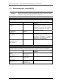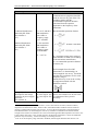
1
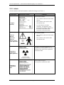
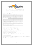
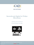
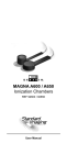
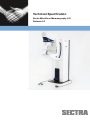
Technical Specification Sectra MicroDose Mammography L30 Software 8.3 Technical Specification – Sectra MicroDose Mammography L30, Software 8.3 Technical Specification Sectra MicroDose Mammography L30 Software 8.3 As part of our commitment to providing the highest quality products and services, we would like to encourage feedback on the quality of this documentation. If you think we can improve this document in any way, please send your suggestions to [email protected] Document Title Revision Date 1007996 H Technical Specification - Sectra MicroDose Mammography L30 Software 8.3 1007996 H 2010-10-22 2 (28) © Sectra 2010 Technical Specification – Sectra MicroDose Mammography L30, Software 8.3 Contents 1. Introduction..................................................................................................................... 4 1.1 1.2 1.3 1.4 1.5 1.6 1.7 2. Purpose ...................................................................................................................... 4 Scope ......................................................................................................................... 4 Intended readers ........................................................................................................ 4 Language ................................................................................................................... 4 Chapter overview ...................................................................................................... 4 Symbols Used in This Document .............................................................................. 4 References ................................................................................................................. 5 Technical specification of the mammography stand ................................................... 6 2.1 Model and manufacturer ........................................................................................... 6 2.2 Regulatory requirements ........................................................................................... 6 2.3 Electromagnetic compatibility .................................................................................. 7 2.4 Installation.................................................................................................................9 2.5 Electrical data .......................................................................................................... 10 2.6 Environment ............................................................................................................ 11 2.7 Heat dissipation and cooling ................................................................................... 12 2.8 Measures and weights ............................................................................................. 13 2.9 Compression............................................................................................................ 16 2.10 X-ray source ............................................................................................................ 16 2.11 X-ray radiation and X-ray protection ...................................................................... 17 2.11.1 Designated zone of occupancy............................................................................ 18 2.12 Generator................................................................................................................. 19 2.13 Exposure.................................................................................................................. 20 2.14 Detector and image parameters ............................................................................... 21 2.15 Acquisition Workstation ......................................................................................... 22 2.16 Labels ...................................................................................................................... 24 1007996 H 3 (28) © Sectra 2010 Technical Specification – Sectra MicroDose Mammography L30, Software 8.3 1. Introduction 1.1 Purpose The purpose of this document is to supply the reader with technical data for the Sectra MicroDose Mammography™ L30 modality. 1.2 Scope The information in this document applies to the Sectra MicroDose Mammography L30 modality. 1.3 Intended readers This document is intended for persons requiring technical data for the Sectra MicroDose Mammography L30 modality. For full understanding of some of the chapters the intended reader is required the knowledge level of an engineer. 1.4 Language This document was originally written in English (UK). In case of uncertainties regarding the content in translated versions of this document, it is the English (UK) version (document number: 1007996) that is to be regarded as the original. 1.5 Chapter overview Chapter 1 – Introduction to this document Chapter 2 – Technical specification of the mammography stand, standard configuration (for screening) 1.6 Symbols Used in This Document Warning! Warning is used when severe danger for patient, personnel or system exists. Caution! Notice Caution is used when danger for patient, personnel or system exists. Notice is used to underline information of importance. Exposure The exposure symbol is used when an exposure is made. 1007996 H 4 (28) © Sectra 2010 Technical Specification – Sectra MicroDose Mammography L30, Software 8.3 1.7 [1] [2] [3] [4] [5] References European Guidelines for Quality Assurance in Breast Screening and Diagnosis, 4th Edition, 2006. S. Eklund, A. Thilander, W. Leitz, S. Mattson, "The impact of anatomic variations on absorbed radiation doses in mammography," Radiat. Prot. Dosim. 49, 167 -17 0 (1993). K. C. Young, M. L. Ramsdale, and F. Bignell, "Review of dosimetric methods for mammography in the UK breast screening programme," Radiat. Prot. Dosim. 80, 183186 (1998). B. Heddson, K. Rönnow, M. Olsson, D. P. Miller, “Digital vs. Screen-Film Mammography: A Retrospective Comparison in a Population-Based Screening Program”, accepted for publication in the European Journal of Radiology. Validation of mobile mammography vehicles, the Sectra Mamea AB document DOCJLUG-7C3CU8. 1007996 H 5 (28) © Sectra 2010 Technical Specification – Sectra MicroDose Mammography L30, Software 8.3 2. Technical specification of the mammography stand Sectra Imtec AB reserves the right to make necessary changes and amendments to the specification below. 2.1 Model and manufacturer Model information Model name Manufacturer 2.2 Sectra MicroDose Mammography L30 Sectra Imtec AB Teknikringen 20 SE 583 30 Linköping Sweden Regulatory requirements European requirements CE labelling National and international standards The system is tested according to the following standards. Class IIb. ”Council Directive 93/42/EEC” concerning medical devices. The product is labelled with the CE mark with identification number 0434 which authenticates the compliance with the directive. IEC 60601-1: 1988 and A1+A21 IEC 60601-1-2:2001 IEC 60601-1-3:1994 IEC 60601-1-4:1996 IEC 60601-2-28:1993 IEC 60601-2-32:19942 IEC 60601-2-45:2001 Equipment classification (according to IEC 60601-1 §5): - Type of protection against electrical shock: Class I equipment - Degree of protection against electrical Type B shock: - Degree of protection against harmful Ordinary equipment ingress of water: - Mode of operation: Continuous operation with intermittent loading, permanent installation. Non-sterilizable equipment Equipment not suitable for use in the presence of a flammable anaesthetic mixture with air or with oxygen or with nitrous oxide. 1 The protective earth impedance between acquisition workstation and incoming protective earth is about 130 mΩ, which exceeds the prescribed maximum level of 100mΩ. The acquisition workstation is connected to floating voltage and the impedance between acquisition workstation and fixed mains switch is about 135 mΩ (prescribed maximum level 200 mΩ). 2 Note: Sectra MicroDose Mammography L30 is equipped with auto positioning (rotation) for the Carm, which is a violation towards the standard IEC 60601-2-32; 22.4.1. The system is however provided with collision protection means and meets the requirement for CE-marking. 1007996 H 6 (28) © Sectra 2010 Technical Specification – Sectra MicroDose Mammography L30, Software 8.3 2.3 Electromagnetic compatibility Caution! The use of accessories, transducers and cables other than those specified by Sectra or sold by Sectra as replacement parts, may result in increased emissions or decreased immunity of the L30 system. Electromagnetic emissions Model L30 is intended for use in the electromagnetic environment specified below. The customer or the user of model L30 should assure that it is used in such an environment. Emission test Compliance Electromagnetic environment – guidance RF emissions Group 1 The L30 uses RF energy only for its CISPR 11 internal function. Therefore, its RF emissions are very low and not likely to cause any interference in nearby electronic equipment. RF emissions Class B CISPR 11 Harmonic emissions Not applicable Model L30 is classified as IEC 61000-3-2 professional equipment and has an active power consumption > 1000W at normal load. According to standards the limits are not applicable. Complies Voltage fluctuations / flicker emissions IEC 61000-3-3 Electromagnetic immunity Model L30 is intended for use in the electromagnetic environment specified below. The customer or the user of model L30 should assure that it is used in such an environment. Immunity test Compliance level Electromagnetic environment – guidance Electrostatic discharge Up to 6 kV contact (ESD) discharge and 8 kV IEC 61000-4-2 air discharge Electrical fast transient / 2 kV for power burst supply lines IEC 61000-4-4 Surge 1 kV differential IEC 61000-4-5 mode, 2 kV common mode 1007996 H 7 (28) © Sectra 2010 Technical Specification – Sectra MicroDose Mammography L30, Software 8.3 Electromagnetic immunity Portable and mobile RF communications equipment should be used no closer to any part of the L30, including cables, than the recommended separation distance calculated from the equation applicable to the frequency of the transmitter. Conducted disturbances induced by RF fields IEC 61000-4-6. (V1) V1 =10 V and 80% AM modulation with 1 kHz at frequency range 0,15 – 80 MHz Radiated disturbances induced by RF fields IEC 61000-4-3 (E1) 10 V/m and 80% AM modulation with 1 kHz at frequency range 80-2500 MHz E1 = 10 V/m Recommended separation distance P = maximum output power rating of the transmitter in watts (W) according to the transmitter manufacturer d = recommended separation distance in metres (m) Field strengths from fixed RF transmitters, as determined by an electromagnetic site survey3 should be less than the compliance level in each frequency range. 4 Interference may occur in the vicinity of equipment marked with the following symbol: Voltage dips, short interruptions and voltage variations on power supply input lines IEC 61000-4-11 >95% dip for 10 ms. 60% dip for 100 ms. 30% dip for 500 ms. Power loss may result in unwanted power off of model L30. In such cases re-calibration of the system is necessary. 3 Note: Field strengths from fixed transmitters, such as base stations for radio (cellular/cordless) telephones and land mobile radios, amateur radio, AM and FM radio broadcast and TV broadcast cannot be predicted theoretically with accuracy. To assess the electromagnetic environment due to fixed RF transmitters, an electromagnetic site survey should be considered. If the measured field strength in the location in which the L30 is used exceeds the applicable RF compliance level above, the L30 should be observed to verify normal operation. If abnormal performance is observed, additional measures may be necessary, such as reorienting or relocating the L30. 4 Note: Over the frequency range 150 kHz to 80 MHz, field strengths should be less than 10 V/m. 1007996 H 8 (28) © Sectra 2010 Technical Specification – Sectra MicroDose Mammography L30, Software 8.3 Electromagnetic immunity Power frequency (50/60 N/A Hz) magnetic field IEC 61000-4-8 The L30 is not sensitive for power frequency magnetic fields. Electromagnetic immunity 2.4 Installation Installation information Installation and service Radiation protection 1007996 H Only personnel certified by Sectra may perform installation and service of the equipment. Installation must be done in accordance with local radiation protection regulations. 9 (28) © Sectra 2010 Technical Specification – Sectra MicroDose Mammography L30, Software 8.3 2.5 Electrical data Electrical Requirements Input mains connection 380/400/415 VAC 50Hz Three phase (protective earth + 3 phases) Fuse 32 A The electrical connection of the equipment shall be permanent Fixed mains switch External, isolated 100 A. Approved according to IEC 328 and IEC 447. The fixed mains switch shall cut supply current by one single action, and shall be possible to lock in OFF mode. The fixed mains switch shall be a mechanical switch, and shall be placed in immediate proximity to the side cabinet. Sectra recommends that, if the side cabinet is not placed in the examination room, an additional switch is placed in the examination room. Input impedance Maximum 0.4Ω Peak power 12 kVA Average power at normal duty cycle 2.5 kVA Duty cycle A 7 second exposure / minute at 35 kV, 200 mA. (Average during one hour.) Power supply cord Required cross sectional area: 10 mm² The power supply cord shall comply with IEC 60245 or IEC 60227. Stranded conductors shall not be soldered. The cord delivered with the system is approximately 5 m (from the cable outlet at the backside of the side cabinet). The diameter is approximately 20 mm. Input mains connection, network isolation, galvanic isolation Network isolation unit, when using network connection Alternative 3 or Alternative 4 (see 2.15). Input mains connection 100-240 V AC, 50-60Hz, single phase Galvanic isolation It is important that the system (except for mains supply) is galvanic isolated from the surrounding. For example water connections, the floor in the examination room and when the system is bolted to the floor of a trailer chassis. 1007996 H 10 (28) © Sectra 2010 Technical Specification – Sectra MicroDose Mammography L30, Software 8.3 2.6 Environment Operating environment - Mammography stand & Acquisition workstation Temperature +10 C to +30 C (at maximum workflow). Temperature change 3 C / hour Humidity 30% to 75 % (non condensing) Atmospheric pressure 700 hPa to 1060 hPa Mechanically active substances like dust and Similar levels to a normal office sand environment, i.e. without special precautions to minimize the presence of sand or dust, but is not situated in proximity to sources of sand or dust. Operating environment - Side cabinet Temperature +10 C to +30 C (maximum work flow). Temperature change 3 C / hour Humidity 30% to 75 % (non condensing) Atmospheric pressure 700 hPa to 1060 hPa Mechanically active substances like dust and Similar levels to a normal office sand environment, i.e. without special precautions to minimize the presence of sand or dust, but is not situated in proximity to sources of sand or dust. Mobile Installations Vehicle requirements See [5] Controlled area Access to the equipment must be restricted in accordance with local regulations. Transport and storage Temperature +5 C to +30 C -10 C to +50 C, less than 1 day Humidity 10% to 75% (non condensing) 95% max, less than 2 weeks Atmospheric pressure 500 hPa to 1060 hPa Mechanically active substances like dust and Similar levels to a normal indoor sand environment, i.e. without special precautions to minimize the presence of sand or dust, but is not situated in proximity to sources of sand or dust. Fire-extinguisher Type Powder 1007996 H 11 (28) © Sectra 2010 Technical Specification – Sectra MicroDose Mammography L30, Software 8.3 2.7 Heat dissipation and cooling Main cabinet with AW table Heat dissipation (total) for both air and water cooled option. Side cabinet: Air cooling (standard configuration) Heat dissipation specification (total) 0.7 kW (maximum work flow) 0.4 kW (stand-by mode) 2.5 kW (maximum work flow) 1.5 kW (stand-by mode) Side cabinet : Water cooling (municipal cooling network) 2.5 kW (maximum work flow) Capacity of water cooling 1.5 kW (stand-by mode) Water cooling (municipal cooling network) Example: If the enclosure temperature is 25°C, the cooling capacity of the water cooler will be 2.5 kW if the water flow is 350 litres/hour, at 100 kPa (nominal) and the incoming water temperature is approximately 6°C. Maximum water flow: 400 litres/hour Water pressure: 1-10 bar (100 – 1000 kPa) Chiller fittings 1007996 H The chiller has G 1/2" (R15) fittings. 12 (28) © Sectra 2010 Technical Specification – Sectra MicroDose Mammography L30, Software 8.3 2.8 Measures and weights Figure 1 1007996 H Measures of Mammography stand. 13 (28) © Sectra 2010 Technical Specification – Sectra MicroDose Mammography L30, Software 8.3 Figure 2 Figure 3 Measures of Side cabinet. Left: Air cooling (standard) Measures of Acquisition Workstation table and radiation protection shield. Mammography stand Measures Weight Measures with packaging Weight with packaging Side cabinet Measures with standard cooling Measures with optional cooling Weight with standard cooling Weight with optional cooling Measures with packaging Weight with packaging 1007996 H Right: Water cooling (optional) See Figure 1 260 kg 800x1800 mm, height 1600 mm 320 kg See Figure 2, left See Figure 2, right 260 kg 260 kg 800x1200 mm, height 1600 mm 300 kg 14 (28) © Sectra 2010 Technical Specification – Sectra MicroDose Mammography L30, Software 8.3 C-arm Height (from floor to patient support) Speed of rotational motion Speed of vertical movement Rotation - standard configuration Automatic positioning (including isocentric C-arm rotation) 760 – 1380 mm 10/second 50 mm/s -100 to + 180 Dx CC, Sin CC, Dx MLO, Sin MLO, Dx LM, Sin LM At compression force greater than 50 N, C-arm movement is not possible. Yes ± 1° 660 mm 640 mm 5 mm Limitation of C-arm movement (vertical movement and rotation) Collision protection Accuracy of display of rotation angle SID (Source Image Distance) Source to patient support distance Missed tissue at chest wall Radiation protection shield Measures See Figure 3 Weight (lead glass shield) 29.5 kg Acquisition Workstation table Measures See Figure 3 Weight 75 kg Network isolation Network isolation unit, when using network connection Alternative 3 or Alternative 4 (see 2.15). To be mounted close to mains electrical outlet. Measures Height: 25 mm Width: 105 mm Depth: 95 mm Weight 0.27 kg Placement Maximum distance between mammography Cable length 6 m. stand and Side Cabinet (from cable outlet to cable outlet). Maximum distance between mammography Cable length 9.5 m stand and Acquisition workstation table (can be adjusted to 19.5 m at request) (from cable outlet to cable outlet). Required free space at both sides of the 600 mm C-arm rotated 90° (either to the left or to the right). Required free space around the side cabinet 200 mm (on all sides, for air circulation) The side cabinet must be placed at the same level as the mammography stand, i.e. it cannot be Placed e.g. one floor upstairs. A designated significant zone of occupancy for the operator is required during exposing. The size of this area shall be at least 60x60x200 cm. Cable routing Total diameter of hoses and cables including Minimum diameter 75 mm. connectors between side cabinet and main cabinet. Total diameter of cables including connectors Minimum diameter 60 mm. between main cabinet and AW-table. 1007996 H 15 (28) © Sectra 2010 Technical Specification – Sectra MicroDose Mammography L30, Software 8.3 2.9 Compression Compression Motion Maximum compression height at exposure Accuracy of display of breast thickness First stop limit for compression Compression force Compression paddles Release of compression Accuracy of display of compression force. 0-150 mm 100 mm (for standard compression paddle) ± 2 mm 12 daN (configurable 0-20 daN) 0 – 200 N - Standard - High edge - Spot (optional) - Low Spot (optional) - Small (optional) - Medium (optional) - Matrix (optional) - Window (optional) - Pedals that control the movement of the compression paddle. - Automatic release after exposure. (Unless the “Keep compression” option has been chosen.) - Release of compression force in case of power loss. - Release of compression force if the emergency stop is activated. ± 20 N 2.10 X-ray source X-ray tube Maximum tube voltage Maximum power to the anode Maximum tube current at maximum tube voltage Maximum tube current Maximum tube voltage at maximum tube current Maximum allowed energy deposition to the anode per hour Anode material Anode disc size Anode rotation speed Focal spot size - standard configuration Anode angle Anode heat capacity Maximum heat radiated from the anode Cooling Accompanying documentation Data sheet X-ray tube 1007996 H 40 kVp 6.8 kW (at 38 kVp, 180 mA) 170 mA at 40 kVp 180 mA 38 kVp at 180 mA 5220 kJ/h (130 500 mAs/h at 40 kVp) Tungsten 102 mm 10800 RPM 0.3 according to IEC 60336 16 (the tube is mounted with a tilt of 7 in a way that 23 angle is achieved relative the reference axis) 445kJ (600 kHU) 1.5 kW (121.5 kHU/min) Oil-air exchanger (fan) Technical Data sheet for Varian RAD-70type tube 16 (28) © Sectra 2010 Technical Specification – Sectra MicroDose Mammography L30, Software 8.3 Service manual X-ray tube Service report X-ray tube X-ray tube Service Manual – Varian #14423 Mammography Tube Service Report – Varian #4989 2.11 X-ray radiation and X-ray protection Relation between mAseff and conventional mAs mAs is tube current exposure time of x-ray tube (not to be confused with the exposure time for a point in the image field). Effective mAs (mAseff) is the mAs corrected for the fraction of open area in the collimator in relation to the total scan length, i.e. this is the mAs that a point in the image plane experiences during a scan. X-ray radiation Inherent filtration from the X-ray tube 0.76 mm Be Added filter 1004803 0.40 mm Al Total filtration (including collimator cradle 0.46 mm Al equivalent at 30 kVp 1004897) Half-value layer after filtering without compression 26 kVp, 0.27 mm Al paddle 32 kVp, 0.34 mm Al (a 3 mm compression paddle increases HVL with 38 kVp, 0.41 mm Al 0.12 mm Al at 30 kVp) (values in-between can be linearly interpolated) Air kerma typical values 45 mm above the patient 0.09 mGy/mAseff at 26 kVp support and 60 mm from the edge of the patient 0.15 mGy/ mAseff at 32 kVp support, compression paddle present. 0.22 mGy/ mAseff at 38 kVp (values in-between can be linearly interpolated) Tube voltage, tube current and exposure time 40 kVp, 170 mA, 15 s providing maximum radiation leakage Dose levels Breast thickness C100 dose C120 dose Acceptable Achievable setting setting level [1] level [1] 3 cm 0.34 – 0.41 0.60 – 0.74 <1.2 <0.9 5 cm 0.40 – 0.49 0.68 – 0.84 <2.3 <1.8 8 cm 0.9 – 1.1 1.2 – 1.4 <5.7 <4.6 Population-averaged 0.5 – 0.6 0.8 – 1.0 n/a n/a Table 1: Measured AGD (mGy) and limiting values from European guidelines [1]. Confidence intervals are 2 standard deviations. Also included are population-based dose values, i.e. dose averaged over a measured breast thickness distribution. Conversion factors were taken from *) *) Further factors for the estimation of mean glandular dose using the United Kingdom, European and IAEA breast dosimetry protocols, D R Dance, K C Young and R E van Engen, Phys Med Biol, 54 (2009), 4361-4372. C100 The C100 dose configuration corresponds to a set of target image quality figures that meet the so-called Acceptable limiting values in the European Guidelines [1]. C120 This dose configuration corresponds to a set of image quality figures that provide 20% higher SDNR (a.k.a. CNR) than the C100 setting. This is equivalent to being able to see 20% thinner objects of the same size. C200 This dose level can only be used with the spot compression paddle and small image field. SDNR is roughly doubled and the dose four times higher compared to C100. Radiation reference axis The radiation reference axis is pointed towards the edge of the digital detector closest to the chest wall. The radiation is collimated in a way that no radiation comes outside the edge of the patient support that is close to the chest wall. Patient support attenuation 1007996 H 17 (28) © Sectra 2010 Technical Specification – Sectra MicroDose Mammography L30, Software 8.3 Patient support 0.05 mm Al equivalence at 30kVp (W anode and HVL 0.3 mm Al) X-ray radiation protection Protective lead glass 0.5 mm Pb equivalent at 55-120kVp 2.11.1 Designated zone of occupancy A designated significant zone of occupancy for the operator is required during exposing. The size shall be at least 60x60x200 cm (W x D x H). Personnel working with the equipment should occupy this zone of occupancy during exposure. Figure 4 defines the zone of occupancy. Figure 4 The zone of occupancy. The radiation protection shield should be positioned in accordance with Figure 4 to minimize the radiation exposure to the operator. 1007996 H 18 (28) © Sectra 2010 Technical Specification – Sectra MicroDose Mammography L30, Software 8.3 Figure 5 The figure illustrates the intensity profile of the scattered radiation as function of height above the floor, with and without the protective lead glass. The data in the figure is normalised to 30,000 exposures. The measurements were performed 120 cm from the scattering volume. 5x30x30 cm3 PMMA in the radiation field was used as scattering volume. The exposure parameters were 40 kVp, 170 mA and 7 s (40 kVp, 10.4 mAs). 2.12 Generator High voltage generator Power kV range mA range Maximum mAs Ripple 1007996 H 9 kW 20 – 40 kVp The system is typically calibrated for only 5 different kVp values. 50 – 210 mA 4000 mAs Max. 1% 19 (28) © Sectra 2010 Technical Specification – Sectra MicroDose Mammography L30, Software 8.3 2.13 Exposure Exposure control Exposure settings Accuracy of kV indicator Accuracy of mAs indicator Termination of exposure Automatic exposure control kVp-range mAs-range SmartAEC™ SmartAEC – acceptable objects 1007996 H SmartAEC™ , Automatic or Manual, where SmartAEC and Automatic are different types of automatic exposure modes. ± 2.0 % ± 10 % The X-ray exposure is terminated when any of the following limits are reached: - the end of the image field (primary) - timeout of scan-time + safety margin (secondary) 26 – 38 kVp Range of effective mAs: Standard Spot image image field field 26 kVp 5.7 – 23 12 – 55 29 kVp 6.2 – 24 13 – 60 32 kVp 6.5 – 26 13 – 63 35 kVp 6.5 – 26 13 – 63 38 kVp 6.5 – 26 13 – 63 SmartAEC exposure mode continuously adjusts the exposure, during the image scan, according to feedback from the detector. For SmartAEC exposure mode, the following objects may be within the AEC area: Breast Hand Skin markers Bracketing wires Standard compression paddle Medium compression paddle Small compression paddle High edge compression paddle 20 (28) © Sectra 2010 Technical Specification – Sectra MicroDose Mammography L30, Software 8.3 SmartAEC– erroneous objects For SmartAEC exposure mode, other objects than the above mentioned within the AEC sensor area, may cause increased patient dose. These foreign objects should be placed outside the AEC sensor area or should be exposed with Automatic or Manual exposure. Automatic Exposure parameters (kV and mAs) are set automatically based on measured thickness during compression. Scanning technology Scan-time Scatter to primary ratio 4 – 16.5 s < 0.05 2.14 Detector and image parameters Digital detector Detector technology Detector material Dynamic resolution Absorption efficiency Dynamic range Pixel size Nyquist frequency Field of View (FOV) Image size (data) Low frequency detective quantum efficiency High frequency detective quantum efficiency Modulation transfer function 1007996 H Photon Counting Crystalline silicon 1 photon 90% for 30 kVp and a 45 mm breast 15 bits 50 µm 10 lp/mm 240 mm × 260 mm (standard mode) 240 mm × 126 mm (configurable only with spot compression) ~50 Mb (uncompressed, standard configuration) >0.65 at 1 mm-1 (measured according to the standard IEC 62220-1-2) >0.24 at 4 mm-1 (measured according to the standard IEC 62220-1-2 and averaged from scan-direction and perpendicular direction) >0.45 at 4 mm-1 on patient support >0.47 at 4 mm-1 45 mm above patient support (MTF measured 6 cm from chest wall and laterally centred, and averaged from scandirection and perpendicular direction) 21 (28) © Sectra 2010 Technical Specification – Sectra MicroDose Mammography L30, Software 8.3 2.15 Acquisition Workstation Hardware Computer CPU Storage capacity Display Keypad with quick-keys Keyboard Mouse Network connection Alternative 1, Gigabit fibre network Alternative 2, 100 Mbps fibre network Alternative 3, Gigabit copper network Alternative 4, 100 Mbps copper network Alternative 5, no network connection Software Operating system DICOM SOP Classes supported 1007996 H PC Pentium 4 / 3.2 GHz (minimum) Up to 2500 (breast) images. Standard Display: Min 19” with 1 Mpx (1280x1024) Optional DICOM Displays: Min 19” with 1 Mpx (1280x1024) Min 21” with 3 Mpx (2048x1536) Yes Yes Yes MMF fibre cable 50/125 or 62.5/125 micron, SC connectors Category 5 cable RJ45 – RJ45 connectors Support for external disk with specification: USB 2.0 interface Hard disk based No separate power supply Minimum storage capacity 160 GB Microsoft Windows XP Professional Verification as SCU (Service Class User) Basic Grayscale Print Management Meta as SCU (not supported in connection alternative 5) Modality Performed Procedure Step (MPPS) as SCU (not supported in connection alternative 5) Digital Mammography Image Storage - For Presentation as SCU Digital Mammography Image Storage - For Processing as SCU Digital X-Ray Image Storage - For Presentation as SCU Digital X-Ray Image Storage - For Processing as SCU Modality Worklist as SCU Storage Commitment Push Model SOP Class as SCU (not supported in connection alternative 5) 22 (28) © Sectra 2010 Technical Specification – Sectra MicroDose Mammography L30, Software 8.3 Parameters visible in the digital image shown on the Acquisition Workstation 1007996 H Always shown parameters: Side Projection Image setting (e.g. ”Implant”) Other parameters are optional, but default for standard breast images are: Patient name Patient ID-number kV and mAs Patient dose (organ dose) Compression height Image time (exposure) 23 (28) © Sectra 2010 Technical Specification – Sectra MicroDose Mammography L30, Software 8.3 2.16 Labels (Serial numbers and batch numbers rendered in images are fictive.) Labelled part Information on label Comment Three identical labels. Complete modality One visible on the back of the main cabinet. One visible on the outside of the side cabinet door. An extra label is provided separately. If required by local regulations, the label is attached to the inside of the hatch of the acquisition workstation table. Two identical labels. Read the Manual, Electronic Waste & Electric Safety, Class B product One visible on the back of the main cabinet. One visible on the outside of the side cabinet door. The label is provided separately. If required by local regulations, the label is attached to the front of the acquisition workstation table. Acquisition workstation table (optional) Label visible on top of the acquisition workstation table. Acquisition workstation table 1007996 H 24 (28) © Sectra 2010 Technical Specification – Sectra MicroDose Mammography L30, Software 8.3 Labelled part Information on label Comment Two identical labels. X-ray tube and main cabinet (optional) One label is attached to the X-ray tube under the C-arm covers. An extra label is provided separately. If required by local regulations, the label is attached either to the underside of the top cover of the main cabinet or to the lower right side of the main cabinet. Label placed on the laser unit intended for wire localization. Laser holder Label visible on the front side. X-ray radiation shield Filter & Collimator cradle assembly Label visible on the mounting device of the X-ray tube. Standard compression paddle Label visible on the side of the compression paddle. Spot compression paddle Label visible on the side of the compression paddle. Small compression paddle Label visible on the side of the compression paddle. Medium compression paddle Label visible on the side of the compression paddle. 1007996 H 25 (28) © Sectra 2010 Technical Specification – Sectra MicroDose Mammography L30, Software 8.3 Labelled part Information on label Comment High edge compression paddle Label visible on the side of the compression paddle. Matrix compression paddle Label visible on the side of the compression paddle. Window compression paddle Label visible on the side of the compression paddle. Low Spot compression paddle Label visible on the side of the compression paddle. Label visible on the side of the Face protection shield. Face protection shield Label visible on the front side of the AWP. Acquisition workstation table Label visible on the side of the Collimator cradle assembly. Pre Collimator with Cradle X-ray tube Label visible on the mounting device of the X-ray tube. Laser holder Label visible on the laser unit intended for wire localization. Label visible on the guidance bracket intended for wire localization. Guidance bracket 1007996 H 26 (28) © Sectra 2010 Technical Specification – Sectra MicroDose Mammography L30, Software 8.3 Labelled part Information on label Comment Label visible on the inside of the side cabinet door. Side cabinet air L30 assembly Label mounted on the inside of the side cabinet door. Side cabinet water cooling L30 assembly Label visible on the front side. Daily quality control phantom Label visible on the front side. Calibration phantom Several identical labels visible outside each of the transport packages. Transport package 1007996 H 27 (28) © Sectra 2010 Manufacturer Sectra Imtec AB Teknikringen 20 SE-583 30 Linköping, Sweden Phone: +46 13 23 52 00 E-mail: [email protected] www.sectra.com/medical For local contact information, visit www.sectra.com/medical/contact © Sectra 2010