1
g
Technical Publications
Direction 5429007-1EN
Rev. 1
Brivo NM 615
Nuclear Medicine Imaging System
Pre-Installation Manual
©2011 by GE Healthcare
ПРЕДУПРЕЖД
ЕНИЕ
(BG)
警告
(ZH-CN)
警告
(ZH-HK)
警告
(ZH-TW)
UPOZORENJE
(HR)
VÝSTRAHA
(CS)
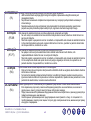
Това упътване за работа е налично само на английски език.
• Ако доставчикът на услугата на клиента изиска друг език, задължение на клиента е да осигури превод.
• Не използвайте оборудването, преди да сте се консултирали и разбрали упътването за работа.
• Неспазването на това предупреждение може да доведе до нараняване на доставчика на услугата,
оператора или пациентa в резултат на токов удар, механична или друга опасност.
本维修手册仅提供英文版本。
• 如果客户的维修服务人员需要非英文版本,则客户需自行提供翻译服务。
• 未详细阅读和完全理解本维修手册之前,不得进行维修。
• 忽略本警告可能对维修服务人员、操作人员或患者造成电击、机械伤害或其他形式的伤害。
本服務手冊僅提供英文版本。
•
倘若客戶的服務供應商需要英文以外之服務手冊,客戶有責任提供翻譯服務。
•
除非已參閱本服務手冊及明白其內容,否則切勿嘗試維修設備。
•
不遵從本警告或會令服務供應商、網絡供應商或病人受到觸電、機械性或其他的危險。
本維修手冊僅有英文版。
•
若客戶的維修廠商需要英文版以外的語言,應由客戶自行提供翻譯服務。
•
請勿試圖維修本設備,除非 您已查閱並瞭解本維修手冊。
•
若未留意本警告,可能導致維修廠商、操作員或病患因觸電、機械或其他危險而受傷。
Ovaj servisni priručnik dostupan je na engleskom jeziku.
•
Ako davatelj usluge klijenta treba neki drugi jezik, klijent je dužan osigurati prijevod.
•
Ne pokušavajte servisirati opremu ako niste u potpunosti pročitali i razumjeli ovaj servisni priručnik.
•
Zanemarite li ovo upozorenje, može doći do ozljede davatelja usluge, operatera ili pacijenta uslijed strujnog
udara, mehaničkih ili drugih rizika.
Tento provozní návod existuje pouze v anglickém jazyce.
• V případě, že externí služba zákazníkům potřebuje návod v jiném jazyce, je zajištění překladu do
odpovídajícího jazyka úkolem zákazníka.
• Nesnažte se o údržbu tohoto zařízení, aniž byste si přečetli tento provozní návod a pochopili jeho obsah.
• V případě nedodržování této výstrahy může dojít k poranění pracovníka prodejního servisu, obslužného
personálu nebo pacientů vlivem elektrického proudu, respektive vlivem mechanických či jiných rizik.
Brivo NM 615 – Pre-Installation Manual
5429007-1EN, Rev. 1, ©2011 GE Healthcare
ii
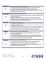
ADVARSEL
(DA)
Denne servicemanual findes kun på engelsk.
• Hvis en kundes tekniker har brug for et andet sprog end engelsk, er det kundens ansvar at sørge for
oversættelse.
• Forsøg ikke at servicere udstyret uden at læse og forstå denne servicemanual.
• Manglende overholdelse af denne advarsel kan medføre skade på grund af elektrisk stød, mekanisk eller
anden fare for teknikeren, operatøren eller patienten.
WAARSCHUWING Deze onderhoudshandleiding is enkel in het Engels verkrijgbaar.
(NL)
•
•
•
WARNING
(EN)
HOIATUS
(ET)
VAROITUS
(FI)
Als het onderhoudspersoneel een andere taal vereist, dan is de klant verantwoordelijk voor de vertaling ervan.
Probeer de apparatuur niet te onderhouden alvorens deze onderhoudshandleiding werd geraadpleegd en
begrepen is.
Indien deze waarschuwing niet wordt opgevolgd, zou het onderhoudspersoneel, de operator of een patiënt
gewond kunnen raken als gevolg van een elektrische schok, mechanische of andere gevaren.
This service manual is available in English only.
• If a customer's service provider requires a language other than english, it is the customer's responsibility to
provide translation services.
• Do not attempt to service the equipment unless this service manual has been consulted and is understood.
• Failure to heed this warning may result in injury to the service provider, operator or patient from electric
shock, mechanical or other hazards.
See teenindusjuhend on saadaval ainult inglise keeles
• Kui klienditeeninduse osutaja nõuab juhendit inglise keelest erinevas keeles, vastutab klient tõlketeenuse
osutamise eest.
• Ärge üritage seadmeid teenindada enne eelnevalt käesoleva teenindusjuhendiga tutvumist ja sellest aru
saamist.
• Käesoleva hoiatuse eiramine võib põhjustada teenuseosutaja, operaatori või patsiendi vigastamist
elektrilöögi, mehaanilise või muu ohu tagajärjel.
Tämä huolto-ohje on saatavilla vain englanniksi.
• Jos asiakkaan huoltohenkilöstö vaatii muuta kuin englanninkielistä materiaalia, tarvittavan käännöksen
hankkiminen on asiakkaan vastuulla.
• Älä yritä korjata laitteistoa ennen kuin olet varmasti lukenut ja ymmärtänyt tämän huolto-ohjeen.
• Mikäli tätä varoitusta ei noudateta, seurauksena voi olla huoltohenkilöstön, laitteiston käyttäjän tai potilaan
vahingoittuminen sähköiskun, mekaanisen vian tai muun vaaratilanteen vuoksi.
Brivo NM 615 – Pre-Installation Manual
5429007-1EN, Rev. 1, ©2011 GE Healthcare
iii
ATTENTION
(FR)
WARNUNG
(DE)
ΠΡΟΕΙ∆ΟΠΟΙΗ
ΣΗ
(EL)
FIGYELMEZTE
TÉS
(HU)
AÐVÖRUN
(IS)
Ce manuel d’installation et de maintenance est disponible uniquement en anglais.
• Si le technicien d'un client a besoin de ce manuel dans une langue autre que l'anglais, il incombe au client
de le faire traduire.
• Ne pas tenter d'intervenir sur les équipements tant que ce manuel d’installation et de maintenance n'a pas
été consulté et compris.
• Le non-respect de cet avertissement peut entraîner chez le technicien, l'opérateur ou le patient des
blessures dues à des dangers électriques, mécaniques ou autres.
Diese Serviceanleitung existiert nur in englischer Sprache.
• Falls ein fremder Kundendienst eine andere Sprache benötigt, ist es Aufgabe des Kunden für eine
entsprechende Übersetzung zu sorgen.
• Versuchen Sie nicht diese Anlage zu warten, ohne diese Serviceanleitung gelesen und verstanden zu
haben.
• Wird diese Warnung nicht beachtet, so kann es zu Verletzungen des Kundendiensttechnikers, des
Bedieners oder des Patienten durch Stromschläge, mechanische oder sonstige Gefahren kommen.
Το παρόν εγχειρίδιο σέρβις διατίθεται μόνο στα αγγλικά.
• Εάν ο τεχνικός σέρβις ενός πελάτη απαιτεί το παρόν εγχειρίδιο σε γλώσσα εκτός των αγγλικών, αποτελεί ευθύνη
του πελάτη να παρέχει τις υπηρεσίες μετάφρασης.
• Μην επιχειρήσετε την εκτέλεση εργασιών σέρβις στον εξοπλισμό αν δεν έχετε συμβουλευτεί και κατανοήσει το
παρόν εγχειρίδιο σέρβις.
• Αν δεν προσέξετε την προειδοποίηση αυτή, ενδέχεται να προκληθεί τραυματισμός στον τεχνικό σέρβις, στο
χειριστή ή στον ασθενή από ηλεκτροπληξία, μηχανικούς ή άλλους κινδύνους.
Ezen karbantartási kézikönyv kizárólag angol nyelven érhető el.
• Ha a vevő szolgáltatója angoltól eltérő nyelvre tart igényt, akkor a vevő felelőssége a fordítás
elkészíttetése.
• Ne próbálja elkezdeni használni a berendezést, amíg a karbantartási kézikönyvben leírtakat nem
értelmezték.
• Ezen figyelmeztetés figyelmen kívül hagyása a szolgáltató, működtető vagy a beteg áramütés, mechanikai
vagy egyéb veszélyhelyzet miatti sérülését eredményezheti.
Þessi þjónustuhandbók er aðeins fáanleg á ensku.
• Ef að þjónustuveitandi viðskiptamanns þarfnast annas tungumáls en ensku, er það skylda viðskiptamanns
að skaffa tungumálaþjónustu.
• Reynið ekki að afgreiða tækið nema að þessi þjónustuhandbók hefur verið skoðuð og skilin.
• Brot á sinna þessari aðvörun getur leitt til meiðsla á þjónustuveitanda, stjórnanda eða sjúklings frá raflosti,
vélrænu eða öðrum áhættum.
Brivo NM 615 – Pre-Installation Manual
5429007-1EN, Rev. 1, ©2011 GE Healthcare
iv
AVVERTENZA
(IT)
警告
(JA)
경고
(KO)
BRDINJUMS
(LV)
ĮSPĖJIMAS
(LT)
ADVARSEL
(NO)
Il presente manuale di manutenzione è disponibile soltanto in lingua inglese.
• Se un addetto alla manutenzione richiede il manuale in una lingua diversa, il cliente è tenuto a provvedere
direttamente alla traduzione.
• Procedere alla manutenzione dell'apparecchiatura solo dopo aver consultato il presente manuale ed averne
compreso il contenuto.
• Il mancato rispetto della presente avvertenza potrebbe causare lesioni all'addetto alla manutenzione,
all'operatore o ai pazienti provocate da scosse elettriche, urti meccanici o altri rischi.
このサービスマニュアルには英語版しかありません。
• サービスを担当される業者が英語以外の言語を要求される場合、翻訳作業はその業者の責任で行うものと
させていただきます。
• このサービスマニュアルを熟読し理解せずに、装置のサービスを行わないでください。
• この警告に従わない場合、サービスを担当される方、操作員あるいは患者さんが、感電や機械的又はその
他の危険により負傷する可能性があります。
본
•
•
•
서비스 매뉴얼은 영어로만 이용하실 수 있습니다 .
고객의 서비스 제공자가 영어 이외의 언어를 요구할 경우 , 번역 서비스를 제공하는 것은 고객의 책임입니다 .
본 서비스 매뉴얼을 참조하여 숙지하지 않은 이상 해당 장비를 수리하려고 시도하지 마십시오 .
본 경고 사항에 유의하지 않으면 전기 쇼크 , 기계적 위험 , 또는 기타 위험으로 인해 서비스 제공자,사용자
또는 환자에게 부상을 입힐 수 있습니다 .
Šī apkopes rokasgrāmata ir pieejama tikai angļu valodā.
• Ja klienta apkopes sniedzējam nepieciešama informācija citā valodā, klienta pienākums ir nodrošināt tulkojumu.
• Neveiciet aprīkojuma apkopi bez apkopes rokasgrāmatas izlasīšanas un saprašanas.
• Šī brīdinājuma neievērošanas rezultātā var rasties elektriskās strāvas trieciena, mehānisku vai citu faktoru
izraisītu traumu risks apkopes sniedzējam, operatoram vai pacientam.
Šis eksploatavimo vadovas yra tik anglų kalba.
• Jei kliento paslaugų tiekėjas reikalauja vadovo kita kalba – ne anglų, suteikti vertimo paslaugas privalo klientas.
• Nemėginkite atlikti įrangos techninės priežiūros, jei neperskaitėte ar nesupratote šio eksploatavimo vadovo.
• Jei nepaisysite šio įspėjimo, galimi paslaugų tiekėjo, operatoriaus ar paciento sužalojimai dėl elektros šoko,
mechaninių ar kitų pavojų.
Denne servicehåndboken finnes bare på engelsk.
• Hvis kundens serviceleverandør har bruk for et annet språk, er det kundens ansvar å sørge for oversettelse.
• Ikke forsøk å reparere utstyret uten at denne servicehåndboken er lest og forstått.
• Manglende hensyn til denne advarselen kan føre til at serviceleverandøren, operatøren eller pasienten skades
på grunn av elektrisk støt, mekaniske eller andre farer.
Brivo NM 615 – Pre-Installation Manual
5429007-1EN, Rev. 1, ©2011 GE Healthcare
v
OSTRZEŻENIE
(PL)
ATENÇÃO
(PT-BR
ATENÇÃO
(PT-PT)
ATENŢIE
(RO)
ОСТОРОЖНО!
(RU)
Niniejszy podręcznik serwisowy dostępny jest jedynie w języku angielskim.
• Jeśli serwisant klienta wymaga języka innego niż angielski, zapewnienie usługi tłumaczenia jest
obowiązkiem klienta.
• Nie próbować serwisować urządzenia bez zapoznania się z niniejszym podręcznikiem serwisowym i
zrozumienia go.
• Niezastosowanie się do tego ostrzeżenia może doprowadzić do obrażeń serwisanta, operatora lub
pacjenta w wyniku porażenia prądem elektrycznym, zagrożenia mechanicznego bądź innego.
Este manual de assistência técnica encontra-se disponível unicamente em inglês.
• Se outro serviço de assistência técnica solicitar a tradução deste manual, caberá ao cliente fornecer os
serviços de tradução.
• Não tente reparar o equipamento sem ter consultado e compreendido este manual de assistência técnica.
• A não observância deste aviso pode ocasionar ferimentos no técnico, operador ou paciente decorrentes
de choques elétricos, mecânicos ou outros.
Este manual de assistência técnica só se encontra disponível em inglês.
• Se qualquer outro serviço de assistência técnica solicitar este manual noutro idioma, é da
responsabilidade do cliente fornecer os serviços de tradução.
• Não tente reparar o equipamento sem ter consultado e compreendido este manual de assistência técnica.
• O não cumprimento deste aviso pode colocar em perigo a segurança do técnico, do operador ou do
paciente devido a choques eléctricos, mecânicos ou outros.
Acest manual de service este disponibil doar în limba engleză.
• Dacă un furnizor de servicii pentru clienţi necesită o altă limbă decât cea engleză, este de datoria clientului
să furnizeze o traducere.
• Nu încercaţi să reparaţi echipamentul decât ulterior consultării şi înţelegerii acestui manual de service.
• Ignorarea acestui avertisment ar putea duce la rănirea depanatorului, operatorului sau pacientului în urma
pericolelor de electrocutare, mecanice sau de altă natură.
Данное руководство по техническому обслуживанию представлено только на английском языке.
• Если сервисному персоналу клиента необходимо руководство не на английском, а на каком-то
другом языке, клиенту следует самостоятельно обеспечить перевод.
• Перед техническим обслуживанием оборудования обязательно обратитесь к данному руководству и
поймите изложенные в нем сведения.
• Несоблюдение требований данного предупреждения может привести к тому, что специалист по
техобслуживанию, оператор или пациент получит удар электрическим током, механическую травму
или другое повреждение.
Brivo NM 615 – Pre-Installation Manual
5429007-1EN, Rev. 1, ©2011 GE Healthcare
vi
UPOZORENJE
(SR)
UPOZORNENIE
(SK)
ATENCION
(ES)
VARNING
(SV)
OPOZORILO
(SL)
Ovo servisno uputstvo je dostupno samo na engleskom jeziku.
• Ako klijentov serviser zahteva neki drugi jezik, klijent je dužan da obezbedi prevodilačke usluge.
• Ne pokušavajte da opravite uređaj ako niste pročitali i razumeli ovo servisno uputstvo.
• Zanemarivanje ovog upozorenja može dovesti do povređivanja servisera, rukovaoca ili pacijenta usled
strujnog udara ili mehaničkih i drugih opasnosti.
Tento návod na obsluhu je k dispozícii len v angličtine.
• Ak zákazníkov poskytovateľ služieb vyžaduje iný jazyk ako angličtinu, poskytnutie prekladateľských služieb
je zodpovednosťou zákazníka.
• Nepokúšajte sa o obsluhu zariadenia, kým si neprečítate návod na obluhu a neporozumiete mu.
• Zanedbanie tohto upozornenia môže spôsobiť zranenie poskytovateľa služieb, obsluhujúcej osoby alebo
pacienta elektrickým prúdom, mechanické alebo iné ohrozenie.
Este manual de servicio sólo existe en inglés.
• Si el encargado de mantenimiento de un cliente necesita un idioma que no sea el inglés, el cliente deberá
encargarse de la traducción del manual.
• No se deberá dar servicio técnico al equipo, sin haber consultado y comprendido este manual de servicio.
• La no observancia del presente aviso puede dar lugar a que el proveedor de servicios, el operador o el
paciente sufran lesiones provocadas por causas eléctricas, mecánicas o de otra naturaleza.
Den här servicehandboken finns bara tillgänglig på engelska.
• Om en kunds servicetekniker har behov av ett annat språk än engelska, ansvarar kunden för att
tillhandahålla översättningstjänster.
• Försök inte utföra service på utrustningen om du inte har läst och förstår den här servicehandboken.
• Om du inte tar hänsyn till den här varningen kan det resultera i skador på serviceteknikern, operatören eller
patienten till följd av elektriska stötar, mekaniska faror eller andra faror.
Ta servisni priročnik je na voljo samo v angleškem jeziku.
• če ponudnik storitve stranke potrebuje priročnik v drugem jeziku, mora stranka zagotoviti prevod.
• Ne poskušajte servisirati opreme, če tega priročnika niste v celoti prebrali in razumeli.
• če tega opozorila ne upoštevate, se lahko zaradi električnega udara, mehanskih ali drugih nevarnosti
poškoduje ponudnik storitev, operater ali bolnik.
Brivo NM 615 – Pre-Installation Manual
5429007-1EN, Rev. 1, ©2011 GE Healthcare
vii
DIKKAT
(TR)
Bu servis kılavuzunun sadece ingilizcesi mevcuttur.
• Eğer müşteri teknisyeni bu kılavuzu ingilizce dışında bir başka lisandan talep ederse, bunu tercüme
ettirmek müşteriye düşer.
• Servis kılavuzunu okuyup anlamadan ekipmanlara müdahale etmeyiniz.
• Bu uyarıya uyulmaması, elektrik, mekanik veya diğer tehlikelerden dolayı teknisyen, operatör veya
hastanın yaralanmasına yol açabilir.
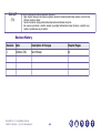
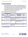
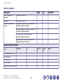
Revision History
Revision
Date
Description of Changes
Chapter/Pages
1
October 2011
New Manual
All
Brivo NM 615 – Pre-Installation Manual
5429007-1EN, Rev. 1, ©2011 GE Healthcare
viii
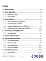
Contents
1.1
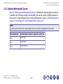
Objectives & Overview. . . . . . . . . . . . . . . . . . . . . . . . . . . . . . . . . . . . . . . . . . . . . . . . . . . . . 1-1
1.2
Customer Responsibilities . . . . . . . . . . . . . . . . . . . . . . . . . . . . . . . . . . . . . . . . . . . . . . . . . . 1-2
1.2.1
1.2.2
1.3
Delivery Requirements. . . . . . . . . . . . . . . . . . . . . . . . . . . . . . . . . . . . . . . . . . . . . . . . . . . . . 1-4
1.3.1
1.3.2
1.3.3
1.3.4
1.4
Using Radioactive Isotopes. . . . . . . . . . . . . . . . . . . . . . . . . . . . . . . . . . . . . . . . . . . 1-3
Project Coordination . . . . . . . . . . . . . . . . . . . . . . . . . . . . . . . . . . . . . . . . . . . . . . . 1-4
General Transportation and Delivery Precautions . . . . . . . . .
Delivery Unloading Area and Equipment . . . . . . . . . . . . . . .
Conveyance of Crated System Components Within the Site . .
Crated and Uncrated Weights, Measurements and Clearance.
.
.
.
.
..
..
..
..
.
.
.
.
.
.
.
.
.
.
.
.
..
..
..
..
.
.
.
.
.
.
.
.
.
.
.
.
..
..
..
..
.
.
.
.
.
.
.
.
.
.
.
.
. . 1-5
. . 1-7
. . 1-8
. 1-10
Product Storage and Handling Requirements . . . . . . . . . . . . . . . . . . . . . . . . . . . . . . . . . 1-16
1.4.1
Storage Requirements . . . . . . . . . . . . . . . . . . . . . . . . . . . . . . . . . . . . . . . . . . . . . 1-16
2.1
Equipment and System Components. . . . . . . . . . . . . . . . . . . . . . . . . . . . . . . . . . . . . . . . . . 2-2
2.2
Room Size, Layout and Considerations . . . . . . . . . . . . . . . . . . . . . . . . . . . . . . . . . . . . . . . . 2-7
2.2.1
2.2.2
2.2.3
2.2.4
2.3
Room Dimension Requirements . . . . . . . . . . . . . . . . . . . . . . . . . . . . . . . . . . . . . . . 2-8
Room Layout Drawings . . . . . . . . . . . . . . . . . . . . . . . . . . . . . . . . . . . . . . . . . . . . . 2-8
System Mechanical Curves . . . . . . . . . . . . . . . . . . . . . . . . . . . . . . . . . . . . . . . . . . 2-12
Room Layout Considerations . . . . . . . . . . . . . . . . . . . . . . . . . . . . . . . . . . . . . . . . 2-14
Room Structural Requirements . . . . . . . . . . . . . . . . . . . . . . . . . . . . . . . . . . . . . . . . . . . . . 2-17
2.3.1
Floor Requirements . . . . . . . . . . . . . . . . . . . . . . . . . . . . . . . . . . . . . . . . . . . . . . . 2-18
Brivo NM 615 – Pre-Installation Manual
5429007-1EN, Rev. 1, ©2011 GE Healthcare
ix
2.3.1.1 Floor Strength. . . . . . . . . . . . . . . . . . . . . . . . . . . . . . . . . . . . . . . . . . . . . . . . .
2.3.1.2 Floor Loading Requirements . . . . . . . . . . . . . . . . . . . . . . . . . . . . . . . . . . . . . . .
2.3.1.3 Floor Anchoring . . . . . . . . . . . . . . . . . . . . . . . . . . . . . . . . . . . . . . . . . . . . . . .
2.3.1.4 Floor Levelness and Flatness . . . . . . . . . . . . . . . . . . . . . . . . . . . . . . . . . . . . . .
2.3.1.5 Floor Vibration . . . . . . . . . . . . . . . . . . . . . . . . . . . . . . . . . . . . . . . . . . . . . . . .
2.3.1.6 Floor Conductivity . . . . . . . . . . . . . . . . . . . . . . . . . . . . . . . . . . . . . . . . . . . . . .
2.3.1.7 Additional Floor Requirements . . . . . . . . . . . . . . . . . . . . . . . . . . . . . . . . . . . . .
2.3.2
Ceiling Requirements . . . . . . . . . . . . . . . . . . . . . . . . . . . . . . . . . . . . . . . . . . . . . .
2.3.3
Wall Requirements . . . . . . . . . . . . . . . . . . . . . . . . . . . . . . . . . . . . . . . . . . . . . . .
2.3.4
Acoustic Specifications . . . . . . . . . . . . . . . . . . . . . . . . . . . . . . . . . . . . . . . . . . . . .
2.3.5
Vibration Specifications . . . . . . . . . . . . . . . . . . . . . . . . . . . . . . . . . . . . . . . . . . . .
2-18
2-19
2-22
2-27
2-28
2-29
2-30
2-30
2-30
2-31
2-31
2.4
Seismic Requirements . . . . . . . . . . . . . . . . . . . . . . . . . . . . . . . . . . . . . . . . . . . . . . . . . . . . 2-33
3.1
Radiation Protection and Shielding Requirements. . . . . . . . . . . . . . . . . . . . . . . . . . . . . . . 3-1
3.1.1
3.1.2
Background Radiation . . . . . . . . . . . . . . . . . . . . . . . . . . . . . . . . . . . . . . . . . . . . . . 3-1
Scan Room Shielding . . . . . . . . . . . . . . . . . . . . . . . . . . . . . . . . . . . . . . . . . . . . . . . 3-2
3.2
Magnetic Field Considerations. . . . . . . . . . . . . . . . . . . . . . . . . . . . . . . . . . . . . . . . . . . . . . . 3-3
3.3
EMI Considerations . . . . . . . . . . . . . . . . . . . . . . . . . . . . . . . . . . . . . . . . . . . . . . . . . . . . . . . 3-3
3.3.1
3.3.2
3.3.3
3.3.4
Electrostatic Discharge Environment & Recommendations . . . . . . . . . . . . . . . . . . . . .
Electro-Magnetic Interference (EMI) . . . . . . . . . . . . . . . . . . . . . . . . . . . . . . . . . . . .
Electromagnetic Immunity . . . . . . . . . . . . . . . . . . . . . . . . . . . . . . . . . . . . . . . . . . .
Recommended Separation Distances . . . . . . . . . . . . . . . . . . . . . . . . . . . . . . . . . . . .
Brivo NM 615 – Pre-Installation Manual
5429007-1EN, Rev. 1, ©2011 GE Healthcare
x
3-3
3-4
3-6
3-6
4.1
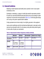
General Guidelines . . . . . . . . . . . . . . . . . . . . . . . . . . . . . . . . . . . . . . . . . . . . . . . . . . . . . . . . 4-2
4.2
Heat Output . . . . . . . . . . . . . . . . . . . . . . . . . . . . . . . . . . . . . . . . . . . . . . . . . . . . . . . . . . . . . 4-3
4.3
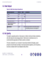
Air Quality . . . . . . . . . . . . . . . . . . . . . . . . . . . . . . . . . . . . . . . . . . . . . . . . . . . . . . . . . . . . . . . 4-3
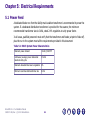
5.1
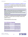
Power Feed . . . . . . . . . . . . . . . . . . . . . . . . . . . . . . . . . . . . . . . . . . . . . . . . . . . . . . . . . . . . . . 5-1
5.2
Power Supply Requirements . . . . . . . . . . . . . . . . . . . . . . . . . . . . . . . . . . . . . . . . . . . . . . . . 5-3
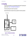
5.3
Grounding . . . . . . . . . . . . . . . . . . . . . . . . . . . . . . . . . . . . . . . . . . . . . . . . . . . . . . . . . . . . . . . 5-5
5.3.1
Grounding of System Input Power. . . . . . . . . . . . . . . . . . . . . . . . . . . . . . . . . . . . . . 5-6
5.4
Interconnections . . . . . . . . . . . . . . . . . . . . . . . . . . . . . . . . . . . . . . . . . . . . . . . . . . . . . . . . . 5-7
5.5
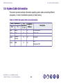
System Cable Information . . . . . . . . . . . . . . . . . . . . . . . . . . . . . . . . . . . . . . . . . . . . . . . . . . 5-9
5.6
Typical Customer Supplied Cables and Wiring . . . . . . . . . . . . . . . . . . . . . . . . . . . . . . . . . 5-10
5.6.1
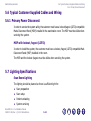
Primary Power Disconnect . . . . . . . . . . . . . . . . . . . . . . . . . . . . . . . . . . . . . . . . . . 5-10
5.7
Lighting Specifications. . . . . . . . . . . . . . . . . . . . . . . . . . . . . . . . . . . . . . . . . . . . . . . . . . . . 5-10
5.8
Power Line Outlets for Service . . . . . . . . . . . . . . . . . . . . . . . . . . . . . . . . . . . . . . . . . . . . . 5-11
Appendix A: Customer Checklist
Appendix B: EMC Compliance
Appendix C: Regulatory Clearances
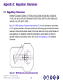
C.1
Regulatory Clearances . . . . . . . . . . . . . . . . . . . . . . . . . . . . . . . . . . . . . . . . . . . . . . . . . . . . . C-1
C.1.1
Regulatory Code Description. . . . . . . . . . . . . . . . . . . . . . . . . . . . . . . . . . . . . . . . . . C-2
Brivo NM 615 – Pre-Installation Manual
5429007-1EN, Rev. 1, ©2011 GE Healthcare
xi
C.1.2
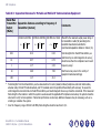
Regulated Minimum Working Clearance by Major Subsystem . . . . . . . . . . . . . . . . . . . C-3
C.1.3
Terms and Definitions . . . . . . . . . . . . . . . . . . . . . . . . . . . . . . . . . . . . . . . . . . . . . . C-8
C.1.4
Additional Regulatory Clearance Information . . . . . . . . . . . . . . . . . . . . . . . . . . . . . C-10
C.1.4.1 Regulatory Caution . . . . . . . . . . . . . . . . . . . . . . . . . . . . . . . . . . . . . . . . . . . . . C-10
C.1.4.2 Egress Clearance. . . . . . . . . . . . . . . . . . . . . . . . . . . . . . . . . . . . . . . . . . . . . . . C-10
C.2
Service Clearances . . . . . . . . . . . . . . . . . . . . . . . . . . . . . . . . . . . . . . . . . . . . . . . . . . . . . . . C-11
Appendix D: Detailed Revision Changes
Brivo NM 615 – Pre-Installation Manual
5429007-1EN, Rev. 1, ©2011 GE Healthcare
xii
List of Figures
1-1
1-2
1-3
2-1
2-2
2-3
2-4
2-5
2-6
2-7
2-8
2-9
2-10
2-11
2-12
2-13
5-2
5-3
C-1
NM Gantry on Dolly Measurements (mm) . . . . . . . . . . . . . . . . . . . . . . . . . . . . . . . . . . . 1-13
B615 Relative Required Width for Corridor and Scan Room Door . . . . . . . . . . . . . . . . . . . 1-14
B615 Required Corridor Width for 90° Turns . . . . . . . . . . . . . . . . . . . . . . . . . . . . . . . . . 1-15
B615 Scan Room Components . . . . . . . . . . . . . . . . . . . . . . . . . . . . . . . . . . . . . . . . . . . . 2-3
B615 Gantry . . . . . . . . . . . . . . . . . . . . . . . . . . . . . . . . . . . . . . . . . . . . . . . . . . . . . . . . . 2-4
B615 Table Views . . . . . . . . . . . . . . . . . . . . . . . . . . . . . . . . . . . . . . . . . . . . . . . . . . . . . 2-5
B615 Collimator Cart . . . . . . . . . . . . . . . . . . . . . . . . . . . . . . . . . . . . . . . . . . . . . . . . . . . 2-6
B615 Minimal Room Layout . . . . . . . . . . . . . . . . . . . . . . . . . . . . . . . . . . . . . . . . . . . . . 2-10
B615 Standard Room Layout . . . . . . . . . . . . . . . . . . . . . . . . . . . . . . . . . . . . . . . . . . . . 2-11
B615 Component Movement Curves . . . . . . . . . . . . . . . . . . . . . . . . . . . . . . . . . . . . . . . 2-13
B615 Floor Loading and Center of Gravity Points for Gantry and Cart . . . . . . . . . . . . . . . . 2-20
B615 Table Center of Gravity Points . . . . . . . . . . . . . . . . . . . . . . . . . . . . . . . . . . . . . . . 2-21
B615 Floor Anchor Points. . . . . . . . . . . . . . . . . . . . . . . . . . . . . . . . . . . . . . . . . . . . . . . 2-23
B615 Drilling Map . . . . . . . . . . . . . . . . . . . . . . . . . . . . . . . . . . . . . . . . . . . . . . . . . . . . 2-24
B615 Gantry Anchoring . . . . . . . . . . . . . . . . . . . . . . . . . . . . . . . . . . . . . . . . . . . . . . . . 2-25
Patient Table Pivot Floor-Plate Anchoring Holes . . . . . . . . . . . . . . . . . . . . . . . . . . . . . . . 2-26
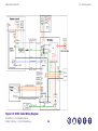
B615 Example of Suggested Cable Ducts Routing in Standard Room . . . . . . . . . . . . . . . . . 5-7
B615 Cable Wiring Diagram . . . . . . . . . . . . . . . . . . . . . . . . . . . . . . . . . . . . . . . . . . . . . . 5-8
B615 Regulatory Clearance Requirements . . . . . . . . . . . . . . . . . . . . . . . . . . . . . . . . . . . . C-1
Brivo NM 615 – Pre-Installation Manual
5429007-1EN, Rev. 1, ©2011 GE Healthcare
xiii
List of Tables
1-1
1-2
1-3
2-1
2-2
2-3
2-4
2-5
3-1
4-1
4-2
5-1
5-2
5-3
5-4
A-1
A-2
A-3
A-4
B615 Components and Clearance — Metric . . . . . . . . . . . . . . . . . . . . . . . . . . . . . . . . . . 1-10
B615 Components and Clearance — Imperial . . . . . . . . . . . . . . . . . . . . . . . . . . . . . . . . 1-12
Storage Conditions . . . . . . . . . . . . . . . . . . . . . . . . . . . . . . . . . . . . . . . . . . . . . . . . . . . 1-17
B615 Components in Scan and Console Rooms . . . . . . . . . . . . . . . . . . . . . . . . . . . . . . . . 2-7
Weights of Components. . . . . . . . . . . . . . . . . . . . . . . . . . . . . . . . . . . . . . . . . . . . . . . . 2-19
B615 Drilling and Anchor Chart . . . . . . . . . . . . . . . . . . . . . . . . . . . . . . . . . . . . . . . . . . 2-25
Floor Leveling Specifications . . . . . . . . . . . . . . . . . . . . . . . . . . . . . . . . . . . . . . . . . . . . 2-28
Subsystem Centers of Gravity and Anchoring Points . . . . . . . . . . . . . . . . . . . . . . . . . . . 2-33
Electro-Magnetic Interference (EMI) Constraints . . . . . . . . . . . . . . . . . . . . . . . . . . . . . . . 3-5
Requirements for Ambient Temperature, Humidity and Altitude. . . . . . . . . . . . . . . . . . . . . 4-2
B615 Heat Output in Scan Room . . . . . . . . . . . . . . . . . . . . . . . . . . . . . . . . . . . . . . . . . . 4-3
B615 System Power Characteristics . . . . . . . . . . . . . . . . . . . . . . . . . . . . . . . . . . . . . . . . 5-1
B615 Nominal Line Voltage Ranges. . . . . . . . . . . . . . . . . . . . . . . . . . . . . . . . . . . . . . . . . 5-2
Power Supply Requirements . . . . . . . . . . . . . . . . . . . . . . . . . . . . . . . . . . . . . . . . . . . . . 5-3
B615 Sub-system Inter-connection Cables. . . . . . . . . . . . . . . . . . . . . . . . . . . . . . . . . . . . 5-9
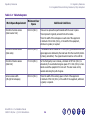
Deviation from Specifications in Site Preparation Manual. . . . . . . . . . . . . . . . . . . . . . . . . . A-2
Site Preparation Time-table . . . . . . . . . . . . . . . . . . . . . . . . . . . . . . . . . . . . . . . . . . . . . . A-2
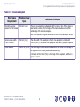
Room Preparation . . . . . . . . . . . . . . . . . . . . . . . . . . . . . . . . . . . . . . . . . . . . . . . . . . . . . A-3
Unloading, Conveyance and Storage . . . . . . . . . . . . . . . . . . . . . . . . . . . . . . . . . . . . . . . . A-5
Brivo NM 615 – Pre-Installation Manual
5429007-1EN, Rev. 1, ©2011 GE Healthcare
xiv
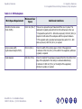
A-5
A-6
B-1
B-2
B-3
C-1
C-2
C-3
C-4
C-5
Network. . . . . . . . . . . . . . . . . . . . . . . . . . . . . . . . . . . . . . . . . . . . . . . . . . . . . . . . . . . .
Radioactive Isotopes for System Calibration . . . . . . . . . . . . . . . . . . . . . . . . . . . . . . . . . .
EMC Emission Declaration . . . . . . . . . . . . . . . . . . . . . . . . . . . . . . . . . . . . . . . . . . . . . . .
EMC Immunity Guidance and Declaration . . . . . . . . . . . . . . . . . . . . . . . . . . . . . . . . . . . .
Separation Distances for Portable and Mobile RF Communications Equipment. . . . . . . . . . .
Gantry Subsystem. . . . . . . . . . . . . . . . . . . . . . . . . . . . . . . . . . . . . . . . . . . . . . . . . . . . .
Table Subsystem . . . . . . . . . . . . . . . . . . . . . . . . . . . . . . . . . . . . . . . . . . . . . . . . . . . . .
Console Subsystem . . . . . . . . . . . . . . . . . . . . . . . . . . . . . . . . . . . . . . . . . . . . . . . . . . . .
UPS Subsystem. . . . . . . . . . . . . . . . . . . . . . . . . . . . . . . . . . . . . . . . . . . . . . . . . . . . . . .
MDP Disconnect Subsystem . . . . . . . . . . . . . . . . . . . . . . . . . . . . . . . . . . . . . . . . . . . . . .
Brivo NM 615 – Pre-Installation Manual
5429007-1EN, Rev. 1, ©2011 GE Healthcare
xv
A-7
A-8
B-1
B-2
B-4
C-3
C-4
C-5
C-6
C-7
Preface
Safety
Preface
Safety
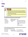
WARNING
This document must be read in conjunction with the System Overview and Safety Manuals (for
Operators and for Service Users), which contain all safety-related information and instructions for
the use and servicing of the system. All users must read and understand the system safety features
and safety operations before using the system.
The images in this manual are for demonstration only. There may be minor differences that do not
affect functionality.
The System Overview and Safety Manual covers information regarding:
Intended use:
Medical purpose
Patient population
Detailed system description
Startup and shutdown
procedures
Operator profile
Safety:
General safety warnings and instructions
Safety mechanisms, procedures and labels
Operator and patient safety during clinical
operation
Equipment and data safety
The Service Safety Manual covers additional service-related safety information not included in the
System Overview and Safety Manual, such as:
Spatial Orientation
Service Clearance
Brivo NM 615 – Pre-Installation Manual
5429007-1EN, Rev. 1, ©2011 GE Healthcare
Service-related safety
Service-related Safety Labels
mechanisms and procedures EMC and Service Tools information
xvi
Preface
Safety
Safety Labels in This Document
This manual addresses three safety classifications:
DANGER
The most severe label describes conditions or actions which result in a specific hazard. You will cause
severe or fatal personal injury, or substantial property damage, if you ignore these instructions.
WARNING
This label identifies conditions or actions which result in a specific hazard.
You may cause severe personal injury, or substantial property damage, if you ignore these instructions.
CAUTION
This label applies to conditions or actions that have potential hazard.
You can cause minor injury or property damage if you ignore these instructions.
Brivo NM 615 – Pre-Installation Manual
5429007-1EN, Rev. 1, ©2011 GE Healthcare
xvii
Preface
System Documentation Set and Online Access
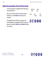
System Documentation Set and Online Access
The service manual set is accessible from the Start page in
the documentation CD.
Click any of the links or buttons to access the relevant
information, or use the Search to search across all
documents.
The navigation bar at the bottom of each page in this
document enables you to page back and forth, to retrace your
steps, and to access the Search index and Start Main Menu
from any page.
Brivo NM 615 – Pre-Installation Manual
5429007-1EN, Rev. 1, ©2011 GE Healthcare
xviii
Main Menu
(Start)
Search
Previous
page
Back
(retrace)
Next
page
Preface
How To Print this Document
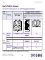
How To Print this Document
This document is created using A5 sheet size. Use the following guidelines when printing:
Print
Dialog
One page per sheet (A5 or A4/Letter)
Property*
Two pages per sheet
(A4 or Letter)
A5 is recommended for a compact book and paper saving
A4/Letter is recommended when large format and print are
needed
14
12
12
13
12
15
13
13
Main
Page Scaling
Fit to Printable Area (removes extra white margins)
Orientation
Double-sided
Page direction /
Printer
Binding
Properties
(Advanced) Number of
pages per sheet
Page Borders
*
N/A
Landscape
Double-sided or (Print on Both Sides)
Open to Side (or Open to Left)
Open to Top or
(Flip pages Up)
Open to Side or
(Open to Left)
2
1
1
Print Page Borders (adds visual
separation between the two pages)
N/A
N/A
Names of properties and options can differ, depending on your specific printer driver
Brivo NM 615 – Pre-Installation Manual
5429007-1EN, Rev. 1, ©2011 GE Healthcare
xix
Preface
Conventions in This Document
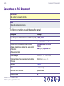
Conventions in This Document
IMPORTANT
Calls attention to important comments.
NOTE
Contains tips and general comments.
The following conventions are used throughout the manual:
Description
Example
Keys on the operator keyboard, hand-held controller and gantry
<SET>, <Ctrl>
Software interface buttons
[OK], [Apply], [Cancel]
Names of items in the graphical interface including:
Configuration tab; To Do List
File menu
Gantry icon; Properties field
Names of dialog boxes, windows, tabs, areas and lists
Menu items
Field and icon labels
System messages
Press Y to continue.
System parameters whose actual values must be defined
by the user
Type-in the Patient ID
Hyperlinks
Figure 3-1
Paths
~/opt/tacqdb
References to other documents
Operator Manual
End of a procedure
Brivo NM 615 – Pre-Installation Manual
5429007-1EN, Rev. 1, ©2011 GE Healthcare
xx
Chapter 1: General System Requirements
1.1 Objectives & Overview
-
This manual provides all information necessary to prepare the site for the installation of the system,
taking into consideration the information required for different professionals such as architects,
construction engineers, electrical contractors, and all other personnel involved in construction and
preparation of the site.
IMPORTANT
Good site preparation is essential for a smooth and efficient installation and for proper functioning of the
system. Poor site planning may compromise system efficiency and/or patient comfort.
The information provided in this Pre-Installation Manual is general in its nature, and must always be used in
conjunction with the drawings and specifications prepared specifically for your site.
Brivo NM 615 – Pre-Installation Manual
5429007-1EN, Rev. 1, ©2011 GE Healthcare
1-1
General System Requirements
1.2 Customer Responsibilities
1.2 Customer Responsibilities
It is the customer’s responsibility to prepare the site in accordance with all the specifications
provided in this manual, and in conjunction with the site-specific drawings. It is essential to verify
all aspects of the site configuration before construction is started, as subsequent changes can be
costly or impractical.
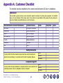
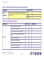
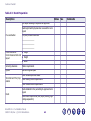
A detailed checklist is provided in App.A, Customer Checklist. It is the customer’s responsibility to
ensure that all requirements in the checklist are fulfilled and that the site conforms with all the
specifications and requirements in this manual.
The customer is responsible for all aspects of site preparation, including, but not limited to, the
following tasks:
Assigning a project coordinator (see Project Coordination, p.1-4)
Planning and construction or renovations required for installation of the system, in accordance
with the specifications included in this manual, including:
Room Size, Layout and Considerations, p.2-7
Equipment Description and General Construction Requirements, p.2-1 and Special
Construction Requirements, p.3-1
Environmental HVAC Requirements, p.4-1
Electrical Requirements, p.5-1
Network Requirements, p.6-1
Brivo NM 615 – Pre-Installation Manual
5429007-1EN, Rev. 1, ©2011 GE Healthcare
1-2
General System Requirements
1.2 Customer Responsibilities
1.2.1 Using Radioactive Isotopes
Complying with all national, state, or local regulatory requirements for the country in which
the installation occurs, for example:
Fire control devices as required by local codes
Permits, inspections, radiation licensing etc.
Earthquake-related regulations
Assuring regulatory compliance for the use of radioactive isotopes and preparation of the
required isotopes (see Using Radioactive Isotopes, p.1-3)
Safe storage of the system and auxiliary equipment prior to and during installation
Floor tile removal and replacement in area of table and gantry
Ensuring adequate accessibility for all system components and auxiliary equipment to the site
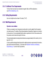
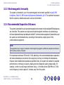
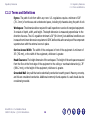
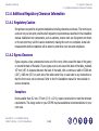
1.2.1 Using Radioactive Isotopes
Since the system involves the use of radioactive isotopes, compliance with Nuclear Regulatory
Commission regulations, or similar regulatory requirements (depending on the country), must be
adhered to and all permissions obtained well in advance. It is recommended that regulatory
compliance is arranged early in the site planning process.
It is essential that all preparations are completed so that required source materials can be obtained
prior to installation, including calibration sources. Take into consideration that these sources may
have fairly long delivery lead times, yet may also have a short half life, so that it may not be
advisable to store them over long periods of time.
Brivo NM 615 – Pre-Installation Manual
5429007-1EN, Rev. 1, ©2011 GE Healthcare
1-3
General System Requirements
1.3 Delivery Requirements
1.2.2 Project Coordination
The site project coordinator is the primary contact and liaison between GE Healthcare and all siterelated functions, including the purchaser, the construction planners, architects and contractors,
and other site administrative personnel.
To insure a successful installation, it recommended that the site nominates a single site project
coordinator, preferably a person familiar with similar medical construction projects, manages the
entire project. Ideally, the project coordinator is involved in every phase from pre-installation and
installation, from conceptual planning through to system start up, working closely with
GE Healthcare to ensure that the client upholds all requirements in this Pre-Installation Manual.
1.3 Delivery Requirements
The system is packed for shipment with minimum tear-down of components.
CAUTION
The system components are sensitive to excessive mishandling, including dropping, shock, vibration, tipping
or hoisting. Vibration damage to components may not be evident until after system installation is complete.
The gantry, console, and table must never be dropped. A drop from a height greater than 1 cm (½")
may induce structural damage to the frame or other major components.
To avoid damage to sensitive components, dock-to-dock shipment is recommended. Other methods
are acceptable, provided the system is not dropped or otherwise mishandled.
Brivo NM 615 – Pre-Installation Manual
5429007-1EN, Rev. 1, ©2011 GE Healthcare
1-4
General System Requirements
1.3 Delivery Requirements
1.3.1 General Transportation and Delivery Precautions
1.3.1 General Transportation and Delivery Precautions
General Temperature Precautions
Extreme temperatures must be avoided during system transportation and delivery. Ensure that
the system is not exposed, for an extended period of time, to temperatures or humidity outside
the following specifications.
Temperature: below -34° and above +5° C (-29°/+140°F)
Humidity: 5% to 95%
NOTE
Component Freezing occurs if the system is exposed to temperatures below -18° C (0° F) for a period of longer
than two days. Allow a minimum of 12 hours for the system to adjust to ambient room temperature, prior to
installation.
Brivo NM 615 – Pre-Installation Manual
5429007-1EN, Rev. 1, ©2011 GE Healthcare
1-5
General System Requirements
1.3 Delivery Requirements
1.3.1 General Transportation and Delivery Precautions
Detector Head Precautions
CAUTION
The detector head is fragile and must always be handled with extra care.
The detector head is extremely sensitive to temperature gradients (sudden changes in temperature).
Failing to comply with the following instructions could cause irreversible damage to the
detector heads.
The detector head must be transported in its original package, which is designed to provide good
mechanical stabilization as well as a certain amount of thermal insulation.
As soon as the detector head is unloaded from the transportation vehicle, it must be moved
to a temperature-controlled area, while still in the original container, until it is ready to be
installed into the system.
If the temperature in the storage or installation areas differs from that of the delivery route
and/or ambient temperature, a stabilization period of 1 hour per 3° C (5.4° F) difference must
be allowed.
Brivo NM 615 – Pre-Installation Manual
5429007-1EN, Rev. 1, ©2011 GE Healthcare
1-6
General System Requirements
1.3 Delivery Requirements
1.3.2 Delivery Unloading Area and Equipment
1.3.2 Delivery Unloading Area and Equipment
The minimal unload area adjacent to the delivery truck is 15m x 15m (50' x 50'). Make sure
that the unloading and storage areas are large enough to maneuver a forklift with crates.
It is recommended that the delivery site is selected to provide the shortest and smoothest
route for component conveyance:
If delivered on the installation day, as close as possible to the scan room for installation
If delivered prior to the installation day, as close as possible to the storage area
If a forklift is required in order to unload or move system components:
Allocate a forklift that is capable of lifting more than the maximum weight of the heaviest
unit (see Table 1-1, B615 Components and Clearance — Metric, p.1-10 or Table 1-2, B615
Components and Clearance — Imperial, p.1-12).
Take into account sufficient floor space to maneuver the forklift near the delivery truck.
Brivo NM 615 – Pre-Installation Manual
5429007-1EN, Rev. 1, ©2011 GE Healthcare
1-7
General System Requirements
1.3 Delivery Requirements
1.3.3 Conveyance of Crated System Components Within the Site
1.3.3 Conveyance of Crated System Components Within the Site
Regardless of whether the system is being delivered from the unloading area to storage, from the
unloading area to unpacking area for installation or from storage to the installation area, take care
to adhere to the following guidelines:
Ensure that there is a free path, including an elevator if necessary, to wheel the components
to the installation area.
Verify that the route selected has sufficient clearance and load carrying capacity (see
Table 1-1, B615 Components and Clearance — Metric, p.1-10 or Table 1-2, B615 Components
and Clearance — Imperial, p.1-12).
The subsystems may be lifted only with a forklift and only when attached to their original
shipping pallets.
CAUTION
Lifting of the gantry without its original shipping pallet or using a crane may damage the system and is
prohibited.
If the outer crating is removed after delivery, do not detach the subsystems from their original
shipping pallets before they are conveyed to the scan room for installation.
The center of gravity of each item, including lifting height and position, is marked on the
subsystem crate. When conveying the subsystems within the site, and particularly if there are
slopes in the delivery path, make sure to take the center of gravity into account.
Always lower system components at the slowest reasonable rate.
Brivo NM 615 – Pre-Installation Manual
5429007-1EN, Rev. 1, ©2011 GE Healthcare
1-8
General System Requirements
1.3 Delivery Requirements
1.3.3 Conveyance of Crated System Components Within the Site
If the system components are to be transferred from an unloading site outside the building,
special facilities must be provided to ensure smooth conveyance.
Uneven temporary ramps may cause vibrations that could damage some components.
System components may be moved via flat-bed tow truck or by rolling them across smooth
sidewalks or other paved surfaces.
When moving the gantry off a flat-bed tow truck, attach the straps to the lowest point possible
on the dolly.
Brivo NM 615 – Pre-Installation Manual
5429007-1EN, Rev. 1, ©2011 GE Healthcare
1-9
General System Requirements
1.3 Delivery Requirements
1.3.4 Crated and Uncrated Weights, Measurements and Clearance
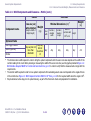
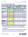
1.3.4 Crated and Uncrated Weights, Measurements and Clearance
The following tables provide you with crate and component measurements, weights and other
data, in order to assist you in planning conveyance routes and storage areas. The order of the
components in the list constitutes the recommended order of conveyance and delivery to the scan
room for installation. The information is provided in metric and imperial formats, as follows:
Table 1-1, B615 Components and Clearance — Metric, p.1-10
Table 1-2, B615 Components and Clearance — Imperial, p.1-12
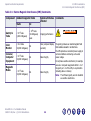
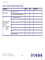
Table 1-1: B615 Components and Clearance — Metric
Crated
Component name
Crate size (cm)
(without dollies)
Uncrated
Weight
Minimal dimensions (cm)*
Weight
(kg)
Door
width
Corridor /
elevator
width
Corridor /
elevator
length
Width of
corridors with
Height
15
any
any
any
any
any
220x150x168
1765
140
140
222
250
200
Table
140x90x300
562
100
100
283
250
any
390
NM acquisition station
80 x 60 x 60
30
any
any
any
any
any
20
50
any
any
any
any
any
50
55
55
100
112
150
(Height x Width x
Depth/Length)
(kg)
Pre-installation kit‡
75 x 40 x 175
NM gantry
Peripherals & accessories
Collimators on carts
115 x 100 x 150
170 x 90 x 115
Brivo NM 615 – Pre-Installation Manual
5429007-1EN, Rev. 1, ©2011 GE Healthcare
273
(heaviest coll.
set)
1-10
90° turns†
15
1590
(with dollies)
233
(heaviest
coll. set)
General System Requirements
1.3 Delivery Requirements
1.3.4 Crated and Uncrated Weights, Measurements and Clearance
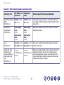
Table 1-1: B615 Components and Clearance — Metric (cont.)
Crated
Component name
Crate size (cm)
(without dollies)
(Height x Width x
Depth/Length)
Uncrated
Weight
(kg)
Weight
Minimal dimensions (cm)*
Door
width
Corridor /
elevator
width
Corridor /
elevator
length
Width of
corridors with
Any
Any
Any
Any
90° turns†
(kg)
Height
Any
Optional Items
ECG Trigger Monitor
Xeleris (optional)
Monitor
*
†
‡
May vary but not
more than
80x80x80
May vary
but not
more than
15
<13
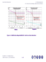
The minimum door width required in order to bring the system components into the scan room also depends on the width of the
corridor leading to the room. When planning or measuring the width of the scan room door, use the graphs provided inFigure 1-2:
B615 Relative Required Width for Corridor and Scan Room Door, p.1-15 in order to verify that the measurements comply with the
requirements.
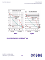
The corridor width required in order to move system components from unloading area to scan room depends on the angles of turns
in the corridor. See Figure 1-3: B615 Required Corridor Width for 90° Turns, p.1-16 for the required width when the angle is 90°.
May be delivered a few days prior to system delivery, as part of the final room check and preparation for installation.
Brivo NM 615 – Pre-Installation Manual
5429007-1EN, Rev. 1, ©2011 GE Healthcare
1-11
General System Requirements
1.3 Delivery Requirements
1.3.4 Crated and Uncrated Weights, Measurements and Clearance
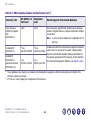
Table 1-2: B615 Components and Clearance — Imperial
Crated
Component name
Pre-installation kit‡
NM gantry
Table
NM acquisition station
Peripherals & accessories
Collimators on carts
Crate size (")
(without dollies)
Uncrated
Weight
Minimal dimensions (“)*
Weight
(lb)
Door
width
Corridor /
elevator
width
Corridor /
elevator
length
Width of
corridors with
33
any
any
any
any
any
86.6x59x66.1
3892
55.1
55.1
88.6
98.4
78.75
55x35.4x118.1
31.5 x 23.62 x 23.62
45.3 x 39.4 x 59
1239
66
110
601
39.4
any
39.4
39.4
any
43.3
111.4
any
59
98.4
any
70.8
any
any
any
22
22
39.4
45.3
59
(heaviest coll.
set)
Any
Any
Any
Any
Any
<28.6
(Height x Width x
Depth/Length)
(lb)
29.5 x 15.7 x 68.9
67x35.4x45.3
(heaviest
coll. set)
May vary but not
more than
31.5x31.5x31.5
May vary
but not
> 33
90° turns†
Height
33
3506
(with dollies)
860
44
110
514
Optional Items
ECG Trigger Monitor
Xeleris (optional)
Monitor
*
†
‡
The minimum door width required in order to bring the system components into the scan room also depends on the width of the
corridor leading to the room. When planning or measuring the width of the scan room door, use the graphs provided in
Figure 1-2: B615 Relative Required Width for Corridor and Scan Room Door, p.1-15 in order to verify that the measurements
comply with the requirements.
The corridor width required in order to move system components from unloading area to scan room depends on the angles of turns
in the corridor. See Figure 1-3: B615 Required Corridor Width for 90° Turns, p.1-16 for the required width when the angle is 90°.
May be delivered a few days prior to system delivery, as part of the final room check and preparation for installation.
Brivo NM 615 – Pre-Installation Manual
5429007-1EN, Rev. 1, ©2011 GE Healthcare
1-12
General System Requirements
1.3 Delivery Requirements
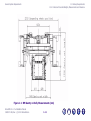
1.3.4 Crated and Uncrated Weights, Measurements and Clearance
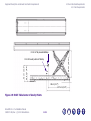
Figure 1-1: NM Gantry on Dolly Measurements (mm)
Brivo NM 615 – Pre-Installation Manual
5429007-1EN, Rev. 1, ©2011 GE Healthcare
1-13
General System Requirements
1.3 Delivery Requirements
1.3.4 Crated and Uncrated Weights, Measurements and Clearance
Imperial
Metric
Figure 1-2: B615 Relative Required Width for Corridor and Scan Room Door
Brivo NM 615 – Pre-Installation Manual
5429007-1EN, Rev. 1, ©2011 GE Healthcare
1-14
General System Requirements
1.3 Delivery Requirements
1.3.4 Crated and Uncrated Weights, Measurements and Clearance
Metric
Imperial
Figure 1-3: B615 Required Corridor Width for 90° Turns
Brivo NM 615 – Pre-Installation Manual
5429007-1EN, Rev. 1, ©2011 GE Healthcare
1-15
General System Requirements
1.4 Product Storage and Handling Requirements
1.4.1 Storage Requirements
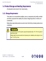
1.4 Product Storage and Handling Requirements
All components must be stored in their original crating.
1.4.1 Storage Requirements
If the system is to be stored before installation, store in a temperature and humidity controlled
environment, and protect from weather, dirt and dust. Storage longer than 12 months is not
recommended.
Meeting these requirements prevents rust and corrosion from forming on bearing surfaces due to
condensation.
CAUTION
Component freezing occurs if the system is exposed to temperatures below -18° C (0° F) for a period of
longer than two days.
Gradually adjust the system to ambient room temperature prior to installation, with a change of no more
than 3° C (5.4° F) per hour.
Brivo NM 615 – Pre-Installation Manual
5429007-1EN, Rev. 1, ©2011 GE Healthcare
1-16
General System Requirements
1.4 Product Storage and Handling Requirements
1.4.1 Storage Requirements
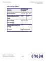
Table 1-3: Storage Conditions
Conditions
Storage temperature
Short term storage
(1-12 months)
+4° to +27°C
40° to +80°F
Maximum temperature rate of
change
3°C/hr.
Relative humidity
(non-condensing)
Between 20% and 60%
Maximum relative humidity rate
of change
5%/hr
Air pressure
Between 700 hPa and 1060 hPa
Brivo NM 615 – Pre-Installation Manual
5429007-1EN, Rev. 1, ©2011 GE Healthcare
1-17
5°F/hr.
Chapter 2: Equipment Description and General
Construction Requirements
This chapter provides the following:
-
Equipment and System Components, p.2-2
Describes the system and its components
Room Size, Layout and Considerations, p.2-7
Provides guidelines for determining the size and layout of the scan and operator rooms and
of the above components, including example layouts of typical rooms, illustrating the position
and dimensions of the components.
Room Structural Requirements, p.2-17
Provides floor, ceiling and wall requirements, and acoustic and vibration specifications for the
scan room and the operator room.
Seismic Requirements, p.2-33
Provides center of gravity information for the different system components.
Brivo NM 615 – Pre-Installation Manual
5429007-1EN, Rev. 1, ©2011 GE Healthcare
2-1
Equipment Description and General Construction Requirements
2.1 Equipment and System Components
2.1 Equipment and System Components
The figures in this section illustrate the different system components.
Figure 2-2: B615 Gantry, p.2-4
Figure 2-3: B615 Table Views, p.2-5
Figure 2-4: B615 Collimator Cart, p.2-6
Brivo NM 615 – Pre-Installation Manual
5429007-1EN, Rev. 1, ©2011 GE Healthcare
2-2
Equipment Description and General Construction Requirements
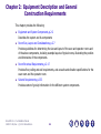
2.1 Equipment and System Components
NM Detector
Collimator carts (see
Figure 2-4, p.2-6)
Boom
P-scope and RCU
Processing Workstations
Patient table (see
Figure 2-3, p.2-5)
Xeleris Workstation (optional)
NM Acquisition Computer
Figure 2-1: B615 Scan Room Components
Brivo NM 615 – Pre-Installation Manual
5429007-1EN, Rev. 1, ©2011 GE Healthcare
2-3
NM gantry (see
Figure 2-2, p.2-4)
Equipment Description and General Construction Requirements
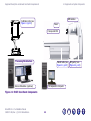
2.1 Equipment and System Components
Figure 2-2: B615 Gantry
Brivo NM 615 – Pre-Installation Manual
5429007-1EN, Rev. 1, ©2011 GE Healthcare
2-4
Equipment Description and General Construction Requirements
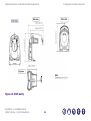
2.1 Equipment and System Components
Figure 2-3: B615 Table Views
Brivo NM 615 – Pre-Installation Manual
5429007-1EN, Rev. 1, ©2011 GE Healthcare
2-5
Equipment Description and General Construction Requirements
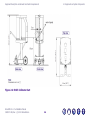
2.1 Equipment and System Components
Figure 2-4: B615 Collimator Cart
Brivo NM 615 – Pre-Installation Manual
5429007-1EN, Rev. 1, ©2011 GE Healthcare
2-6
Equipment Description and General Construction Requirements
2.2 Room Size, Layout and Considerations
2.2 Room Size, Layout and Considerations
The system requires a main Scan Room, which contains the following sub-systems:
Table 2-1: B615 Components in Scan and Console Rooms
Scan Room
Fixed Components
Moving Components
(seeFigure 2-1, p.2-3)
NM Gantry
Collimator carts
Patient table
NM acquisition station
MDP
This section provides guidelines for determining the size and layout of the scan and operator rooms
and of the above components, and example layouts of typical rooms, illustrating the position and
dimensions of the components.
The room layouts provided take into consideration all aspects of operation, operator and patient
requirements and service clearance requirements.
Brivo NM 615 – Pre-Installation Manual
5429007-1EN, Rev. 1, ©2011 GE Healthcare
2-7
Equipment Description and General Construction Requirements
2.2 Room Size, Layout and Considerations
2.2.1 Room Dimension Requirements
Egress
The room layouts, diagrams and dimensions in this manual provide the required clearances for
proper equipment operation and service only. The customer/purchaser is responsible for
compliance with federal, state and/or local codes regarding facility egress and related facility
requirements.
2.2.1 Room Dimension Requirements
NOTE
The minimal and standard scan rooms described in this manual may not comply with specific local/regional/country/
state requirements (such as OSHA in the USA).Take into consideration the local regulations in force when planning
room dimensions and layout.
Minimal scan room size, without operator room (L x W x H)
5.12 m x 3.74 m x 2.3 m (16' 9'' x 12' 3'' x 7' 6'')
(see Figure 2-5: B615 Minimal Room Layout, p.2-10)
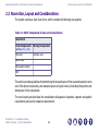
2.2.2 Room Layout Drawings
This section provides typical sample room layouts, illustrating the position and dimensions of the
scan room and of the system components, including:
Figure 2-5: B615 Minimal Room Layout, p.2-10
Figure 2-6: B615 Standard Room Layout, p.2-11
Brivo NM 615 – Pre-Installation Manual
5429007-1EN, Rev. 1, ©2011 GE Healthcare
2-8
Equipment Description and General Construction Requirements
2.2 Room Size, Layout and Considerations
2.2.2 Room Layout Drawings
The room layout dimensions take into consideration all aspects of operation, operator and patient
requirements, safety regulations and service clearance requirements (see Room Layout
Considerations, p.2-14).
Brivo NM 615 – Pre-Installation Manual
5429007-1EN, Rev. 1, ©2011 GE Healthcare
2-9
Equipment Description and General Construction Requirements
2.2 Room Size, Layout and Considerations
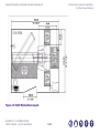
2.2.2 Room Layout Drawings
Figure 2-5: B615 Minimal Room Layout
Brivo NM 615 – Pre-Installation Manual
5429007-1EN, Rev. 1, ©2011 GE Healthcare
2-10
Equipment Description and General Construction Requirements
2.2 Room Size, Layout and Considerations
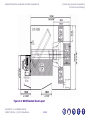
2.2.2 Room Layout Drawings
Figure 2-6: B615 Standard Room Layout
Brivo NM 615 – Pre-Installation Manual
5429007-1EN, Rev. 1, ©2011 GE Healthcare
2-11
Equipment Description and General Construction Requirements
2.2 Room Size, Layout and Considerations
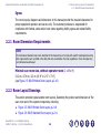
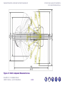
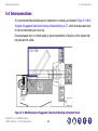
2.2.3 System Mechanical Curves
2.2.3 System Mechanical Curves
Figure 2-7: B615 Component Movement Curves, p.2-13 illustrates the table and gantry movement.
In addition, the ECG trigger monitor and collimator carts can be moved to different locations in
the scan room, as demonstrated in the room layout illustrations in Figure 2-5: B615 Minimal Room
Layout, p.2-10 and Figure 2-6: B615 Standard Room Layout, p.2-11.
NOTE
In order to prevent collision with the gantry display boom, do not mount any equipment from the ceiling.
Table slanted at
Farthest point relative to system's center line
67.5°
186 cm (73")
55°
172 cm (67.7')
42.5°
148.5 cm (58.5")
Brivo NM 615 – Pre-Installation Manual
5429007-1EN, Rev. 1, ©2011 GE Healthcare
2-12
Equipment Description and General Construction Requirements
2.2 Room Size, Layout and Considerations
2.2.3 System Mechanical Curves
Figure 2-7: B615 Component Movement Curves
Brivo NM 615 – Pre-Installation Manual
5429007-1EN, Rev. 1, ©2011 GE Healthcare
2-13
Equipment Description and General Construction Requirements
2.2 Room Size, Layout and Considerations
2.2.4 Room Layout Considerations
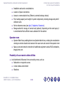
2.2.4 Room Layout Considerations
This section describes the considerations you must take into account when selecting a site and
planning the room size and layout. In addition, it is the responsibility of the customer to ensure
that all aspects of the scan and operator rooms conform with the local requirements.
Scan Room Dimensions and System Placement
The room size and shape and the placement of the system components must enable optimal
functional and working conditions, including the best possible relative positioning of the gantry,
patient table and acquisition console in operator room, including:
Operator access in scan room, around the gantry and patient table in order to:
Assist patient positioning
Perform examination routines
Act efficiently and quickly in case of an emergency, including easy access to emergency
switch
Operation-related considerations:
Enable access for hospital beds, including maneuvering and positioning the bed and moving
the front of the patient table during collimator exchange
Storage of the collimator carts (one for each set of collimators) when not in use
ECG Trigger Monitor – cable position and lengths and storage when not in use
Space for storage and usage of ECG Trigger Monitor
Brivo NM 615 – Pre-Installation Manual
5429007-1EN, Rev. 1, ©2011 GE Healthcare
2-14
Equipment Description and General Construction Requirements
2.2 Room Size, Layout and Considerations
2.2.4 Room Layout Considerations
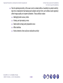
Installation and service considerations:
Location of power connections
Access to communication lines (Ethernet, external hardcopy device)
Floor loading capacity and weight of system components, including storage and path of
collimator carts
Service clearance areas (see App.C, Regulatory Clearances)
Storage cabinet for storage of service tools (optional). Depending on the room layout, it
is recommended that sufficient area is allocated for the cabinet.
Operator room
Operator field of view, enabling direct view of patient table in bore, or taking into consideration
viewing via remote closed-circuit camera in the scan room and screen in the operator room
Space, power and network connections for additional equipment such as PACS workstation,
image printer, etc.
Proximity of scan room to other utilities
Avoid detrimental influences from surrounding rooms, such as:
Radioactive or magnetic sources
A local wireless environment
Vibrations
Brivo NM 615 – Pre-Installation Manual
5429007-1EN, Rev. 1, ©2011 GE Healthcare
2-15
Equipment Description and General Construction Requirements
2.2 Room Size, Layout and Considerations
2.2.4 Room Layout Considerations
Plan the optimal proximity of the scan room to related utilities. In addition to patient comfort,
take into consideration that background radiation activity from such utilities could negatively
affect image quality and system calibration. These utilities include:
Waiting/injection areas, toilets
Viewing and processing rooms
Radionuclide storage and preparation area
Office facilities
Smoke detectors that use/have radioactive activity
Brivo NM 615 – Pre-Installation Manual
5429007-1EN, Rev. 1, ©2011 GE Healthcare
2-16
Equipment Description and General Construction Requirements
2.3 Room Structural Requirements
2.3 Room Structural Requirements
Room requirements consist of the following:
Floor Requirements, p.2-18, including floor strength, anchoring, levelness and flatness,
vibration and conductivity
Floor Loading Requirements, p.2-19
Ceiling Requirements, p.2-30
Wall Requirements, p.2-30
Acoustic Specifications, p.2-31
Vibration Specifications, p.2-31
Brivo NM 615 – Pre-Installation Manual
5429007-1EN, Rev. 1, ©2011 GE Healthcare
2-17
Equipment Description and General Construction Requirements
2.3 Room Structural Requirements
2.3.1 Floor Requirements
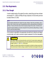
2.3.1 Floor Requirements
2.3.1.1 Floor Strength
In order to enable mounting of the system floor anchors, concrete floors must have a minimum
cube strength of f'c = 4350 psi (30 MPa) at 28 days (curing time) for 25/30 concrete, and must
be at least 140 mm (5.5") thick.
NOTE
Concrete strength is determined by the “Cylinder Test” (used in the USA) or “Cube Test” (used in Europe), where a
cylinder or cube of concrete is cast, cured for the appropriate time and then compressed between two parallel faces
until failure. The stress at the failure is taken to be the compressive strength of the concrete. The 25/30 concrete
required for the system installation is concrete with a strength of 25 in the cylinder test (resulting 3625 psi), or strength
of 30 in the cube test (resulting 4350 psi).
It is the customer’s responsibility to have appropriate tests performed to determine and measure
concrete strength, and to obtain a constructor engineer’s assessment for the floor load capability.
CAUTION
If the system is installed on a floor type thinner than a 140 mm (5.5") concrete floor, the customer shall,
at their expense, provide acceptable anchoring and mounting methods that meet all structural specifications
provided in sections 2.3.1.2 and 2.3.1.3 of this manual.
In addition, the customer shall ensure that the floor strength in the collimator cart storage area and along
the movement routes for collimator exchange are suitable for the collimator cart load (approx. 250 kg each).
Brivo NM 615 – Pre-Installation Manual
5429007-1EN, Rev. 1, ©2011 GE Healthcare
2-18
Equipment Description and General Construction Requirements
2.3 Room Structural Requirements
2.3.1 Floor Requirements
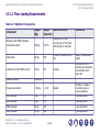
2.3.1.2 Floor Loading Requirements
Table 2-2: Weights of Components
Component
Weight
(Kg)
Weight
Load Distribution
(Imperial)
NM gantry (with HEGP collimators
mounted on system)
1595 kg
3517 lb
Patient table
390 kg
860
Comments
4 pads, Ø83 mm each:
+514 kg each on front pads
+283 kg each on rear pads
4 wheels + axis anchored to
floor
Weight of table without
patient
514
4 wheels
COG point at 81 cm
height; may be more than
one collimator cart in
scan room
Variable
Normally 3-4 people in
room during scan or
service operations
Collimator cart (with HEGP on cart)
233 kg
Acquisition station
(insignificant)
Personnel and patient
< 500 kg
< 1102
LEHR collimator
62 kg
137
1 per system/cart
LEGP collimator
55 kg
121
1 per system/cart
MEGP collimator
103 kg
227
1 per system/cart
HEGP collimator
131 kg
288
1 per system/cart
Brivo NM 615 – Pre-Installation Manual
5429007-1EN, Rev. 1, ©2011 GE Healthcare
2-19
Equipment Description and General Construction Requirements
2.3 Room Structural Requirements
2.3.1 Floor Requirements
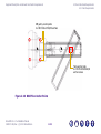
Gantry rear pads
283.5 kg load per pad
Gantry front pads
514 kg load per pad
28.8 cm
Gantry center of
gravity 1595 kg
Table center of gravity 390 kg
load (distributed on 4 wheels
+ pivot)
Collimator cart center of
gravity 233 kg load, including
collimator; up to 3 carts in the
scan room.
Figure 2-8: B615 Floor Loading and Center of Gravity Points for Gantry and Cart
Brivo NM 615 – Pre-Installation Manual
5429007-1EN, Rev. 1, ©2011 GE Healthcare
2-20
Equipment Description and General Construction Requirements
2.3 Room Structural Requirements
2.3.1 Floor Requirements
68 cm (26.77")
C.O.G. for fully elevated tabletop
22.5 cm (8.9")
52 cm (20.5")
C.O.G for lowest position of tabletop
106 cm (41.7")
107.5 cm (42.3")
Figure 2-9: B615 Table Center of Gravity Points
Brivo NM 615 – Pre-Installation Manual
5429007-1EN, Rev. 1, ©2011 GE Healthcare
2-21
Equipment Description and General Construction Requirements
2.3 Room Structural Requirements
2.3.1 Floor Requirements
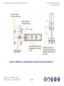
2.3.1.3 Floor Anchoring
The system’s floor anchors are designed for use only on concrete floors that meet the minimal
140 mm (5.5")concrete floor requirements.
CAUTION
For concrete floors thinner than 140 mm or different floor types other anchoring methods might be required.
These must comply with the minimum load requirements (see Floor Loading Requirements, p.2-19) and
must be installed and tested at the customer’s expense, by the customer’s structural contractor. The selected
anchoring method must have a pulling tensile force of 37.7 kN on each of the anchors bolting the NM Gantry
to the floor.
In such a case, the alternative anchors shall be installed during system installation, and this must be
coordinated with the installation team. For anchor point information, see Figure 2-10: B615 Floor Anchor
Points, p.2-23.
Brivo NM 615 – Pre-Installation Manual
5429007-1EN, Rev. 1, ©2011 GE Healthcare
2-22
Equipment Description and General Construction Requirements
2.3 Room Structural Requirements
2.3.1 Floor Requirements
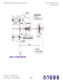
NM gantry anchor points
4 x HILTI-HSL-3 M10/20 anchors
Table anchor plate
6 x HILTI-HLC6.5x60/40
anchor screws
Figure 2-10: B615 Floor Anchor Points
Brivo NM 615 – Pre-Installation Manual
5429007-1EN, Rev. 1, ©2011 GE Healthcare
2-23
Equipment Description and General Construction Requirements
2.3 Room Structural Requirements
2.3.1 Floor Requirements
Figure 2-11: B615 Drilling Map
Brivo NM 615 – Pre-Installation Manual
5429007-1EN, Rev. 1, ©2011 GE Healthcare
2-24
Equipment Description and General Construction Requirements
No.
X
Y
1
2
3
4
5
6
7
8
-0.00
-0.00
-810.00
-810.00
-80.00
-80.00
-810.00
-810.00
405.00
-405.00
405.00
-405.00
365.00
-365.00
530.00
-530.00
Drill
Hole
Hole
Depth
2.3 Room Structural Requirements
2.3.1 Floor Requirements
Anchored Part
Drilling
Method
Anchor Type Torque Nm.
Main Anchor
90
NM Gantry
Alternative Anchor
Figure 2-12: B615 Gantry Anchoring
2-25
Section
Figure 2-12
Metal Drilling
Template
Ø15.0
Table 2-3: B615 Drilling and Anchor Chart
Brivo NM 615 – Pre-Installation Manual
5429007-1EN, Rev. 1, ©2011 GE Healthcare
Hole Purpose
HILTI
HSL-3 M10/
20
35
Figure 2-10
Equipment Description and General Construction Requirements
2.3 Room Structural Requirements
2.3.1 Floor Requirements
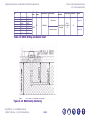
Figure 2-13: Patient Table Pivot Floor-Plate Anchoring Holes
Brivo NM 615 – Pre-Installation Manual
5429007-1EN, Rev. 1, ©2011 GE Healthcare
2-26
Equipment Description and General Construction Requirements
2.3 Room Structural Requirements
2.3.1 Floor Requirements
2.3.1.4 Floor Levelness and Flatness
The scan room floor must be leveled, and its surface must be smooth.
It is recommended that the floor in the entire scan room is leveled and flattened. If this is not
possible, it is a minimum requirement for the gantry/table installation area to be level and flat.
The floor levelness requirement is essential for proper alignment of the table and the gantry, which
affects accurate patient positioning, collimator exchange and other aspects of system functionality.
Table level may not be achievable if overall floor levelness does not conform to these specifications.
CAUTION
The use of floor shims is not suitable to achieve floor levelness.
Do not use fill material to compensate for holes or depressions in the floor surface.
If necessary, level and flatten the entire floor area.
NOTE
Instructions for determining floor flatness and levelness are provided in the system’s Installation Manual.
Brivo NM 615 – Pre-Installation Manual
5429007-1EN, Rev. 1, ©2011 GE Healthcare
2-27
Equipment Description and General Construction Requirements
2.3 Room Structural Requirements
2.3.1 Floor Requirements
Table 2-4: Floor Leveling Specifications
ti
Item
Requirement
Floor leveling area
512 cm x 374 cm (16'-9" x 12'-2") (covering the entire planned area of table and
gantry installation, depending on room layout)
Slope
3 mm (0.125") over 3048 mm (120")
Flatness
The surface must be smooth, with deviations of no more than 0.5 cm (3/16")
between depressions and high spots in any 150 cm (60") throughout the room or
system installation area
Floor surface
A single poured surface
2.3.1.5 Floor Vibration
Floor vibration requirements are included in the general vibration requirements
(see Vibration Specifications, p.2-31).
Brivo NM 615 – Pre-Installation Manual
5429007-1EN, Rev. 1, ©2011 GE Healthcare
2-28
Equipment Description and General Construction Requirements
2.3 Room Structural Requirements
2.3.1 Floor Requirements
2.3.1.6 Floor Conductivity
The purpose of this section is to measure the electrical conductivity of the floor surface to the
“GND” (Ground).
The surface of the conductive floor shall provide a patch of electrical conductivity between all
persons and equipment making contact with the floor.
Using a DVM, measure the impedance between the upper surface of the floor – where the NM
Gantry is planned to be positioned, and the System power supply GND terminal in the room.
The readout needs to be less than 35 M Ohm.
Repeat the measurement in the area where the Patient Table will be positioned. The readout
needs to be less than 35 M Ohms.
Brivo NM 615 – Pre-Installation Manual
5429007-1EN, Rev. 1, ©2011 GE Healthcare
2-29
Equipment Description and General Construction Requirements
2.3 Room Structural Requirements
2.3.2 Ceiling Requirements
2.3.1.7 Additional Floor Requirements
The floor finish must take into consideration magnetic field and EMI considerations
(see EMI Considerations, p.3-3).
2.3.2 Ceiling Requirements
Scan room height must be at least 2.3 meters (7' 6.5").
2.3.3 Wall Requirements
Operator room window
If there is an operator room, the operator must be able to view the patient from the operator
room during a scan. The location of the window depends on the position of operator room relative
to the scan room. It is recommended that the window is positioned in front of the console so that
the operator can look down the length of the bore.
The recommended patient viewing window dimensions are approximately 120 cm wide by 110 cm
high (48" x 42").
Consult a qualified radiological health physicist for radiation protection requirements for the window
glass (lead content and thickness), in accordance with Radiation Protection and Shielding
Requirements, p.3-1 and with local requirements.
Brivo NM 615 – Pre-Installation Manual
5429007-1EN, Rev. 1, ©2011 GE Healthcare
2-30
Equipment Description and General Construction Requirements
2.3 Room Structural Requirements
2.3.4 Acoustic Specifications
Radiation protection
For details on wall, door and window radiation protection, (see Radiation Protection and Shielding
Requirements, p.3-1).
Other
Verify that all walls conform with local regulations, such as washability.
2.3.4 Acoustic Specifications
The system creates acoustic noise. In compliance with IEC 601-1-1standard the measured noise
(at 1m distance away from the system) is less than 70 db. It is recommended that the wall and
ceiling surface is of a sound dampening material so that the noise is not reverberated and amplified.
2.3.5 Vibration Specifications
The system components are sensitive to vibration in the frequency range of 0.5 to 20 Hz, depending
on the amplitude of the vibration. It is the customer’s responsibility to contract a vibration consultant
or qualified engineer to verify that these specifications are met and implement an appropriate
solution.
To minimize vibrations, the system must be installed on a solid floor, as far as possible from the
following vibration sources:
Brivo NM 615 – Pre-Installation Manual
5429007-1EN, Rev. 1, ©2011 GE Healthcare
2-31
Equipment Description and General Construction Requirements
Outside building
2.3 Room Structural Requirements
2.3.5 Vibration Specifications
Inside building
Parking lots
Hallways
Roadways
Elevators
Subways
Heliports
Trains
Other
Hospital power plants
containing pumps, motors, air
handling equipment and air
conditioning units
Steady State Vibration
The maximum steady state vibration transmitted through the floor should not exceed
0.001 m/s2 RMS maximum single frequency above ambient baseline from 0.5 to 80 Hz
(measured in any 1 hour during a normal operating period).
Transient Vibration
The behavioral characteristics must be such that any measurable transient disturbance must also
be minimized to less than 0.01 m/s2 peak-to-peak.
Brivo NM 615 – Pre-Installation Manual
5429007-1EN, Rev. 1, ©2011 GE Healthcare
2-32
Equipment Description and General Construction Requirements
2.4 Seismic Requirements
2.4 Seismic Requirements
Seismic requirements are determined and specified by the hospital design professional of record
and must be approved by the specific state or country agency. Seismic attachment hardware shown
on seismic calculations may differ from hardware supplied with system. Any additional hardware
that is required will be the responsibility of the institution and/or their contractor.
For additional center of gravity information, see Table 2-5, p.2-33.
Table 2-5: Subsystem Centers of Gravity and Anchoring Points
Component
Table
NM gantry
Collimator carts
†
Center of Gravity Location
(cm)
Regular Anchoring
Additional Anchoring
in Seismic Areas
X
Y
Z
106
25
52
Anchor plate + 6 screws No additional anchoring required
6 x HILTI-HLC 6.5 x 60/40
98
4 x HILTI HSL-3 M10/20
anchors
81
Carts cannot be anchored, as they must move freely in the room
for collimator exchange
0*
48.5
10.1
19.5
In the most unfavorable configuration
Brivo NM 615 – Pre-Installation Manual
5429007-1EN, Rev. 1, ©2011 GE Healthcare
2-33
See also
Figure 2-9, p.2-21
Can add 4 anchoring points using four Figure 2-10, p.2-23
redundant anchoring holes on NM
gantry
Figure 2-4, p.2-6
Chapter 3: Special Construction Requirements
3.1 Radiation Protection and Shielding Requirements
Radiation shielding regulations differ from one country or state to another. It is the customer’s
responsibility to ensure that radiation protection and shielding comply with such regulations and
requirements during site preparation and system installation and operation.
3.1.1 Background Radiation
When the system is calibrated, background radiation from surrounding areas may adversely affect
calibration. Therefore all radiation sources must be suitably shielded, including:
Waiting/Injection areas
Radionuclide storage and preparation area (sometimes known as “hot lab”)
As a general guideline, if the anticipated background radiation in the Scan Room will be higher
than 0.1mR/h (1microGy/h), then lead shielding with sufficient thickness must be installed.
NOTE
In most cases, a 2-5 mm lead wall will sufficiently reduce background radiation levels. To optimize costs, it is recommended
that you consult with a specialist to determine the minimum lead thickness for the planned installation site.
Brivo NM 615 – Pre-Installation Manual
5429007-1EN, Rev. 1, ©2011 GE Healthcare
3-1
-
Special Construction Requirements
3.1 Radiation Protection and Shielding Requirements
3.1.2 Scan Room Shielding
3.1.2 Scan Room Shielding
The system involves the use and storage of radio nuclides. Appropriate barriers such as walls,
lead-shielded glass, lead shields, etc. must be installed to protect staff from unnecessary exposure
to radiation.
Patients become significant sources of radioactivity; therefore consideration should be given to
maximize the distance between the patient and operator during the uptake and acquisition phases
of scan procedures.
Scatter-room shielding requirements must be reviewed by a qualified radiological health physicist
taking into consideration:
Scatter radiation levels within the scanning room
Equipment Placement
Weekly projected workloads (#patient/day technique (kvp*ma)
Materials used for construction of walls, floors, ceilings, doors and windows
Access to surrounding scan room areas
Equipment in surrounding scan room area (e.g. film developer, film storage)
CAUTION
Specific room shielding requirements should be determined by local regulatory considerations, facility policy
and if available, the facility physicist.
Brivo NM 615 – Pre-Installation Manual
5429007-1EN, Rev. 1, ©2011 GE Healthcare
3-2
Special Construction Requirements
3.2 Magnetic Field Considerations
3.2 Magnetic Field Considerations
Low Frequency Magnetic Field
N/A
Static Magnetic Field Limits
In order to avoid interference on the system, the static field limits from the surrounding environment
must be less than 1 Gauss in both the scan and the operator rooms.
3.3 EMI Considerations
3.3.1 Electrostatic Discharge Environment & Recommendations
In order to reduce electrostatic discharge interference, install a charge dissipative floor material
to avoid electrostatic charge buildup.
The relative humidity shall be at least 30 percent.
The dissipative material shall be connected to the system ground reference, if applicable.
Brivo NM 615 – Pre-Installation Manual
5429007-1EN, Rev. 1, ©2011 GE Healthcare
3-3
Special Construction Requirements
3.3 EMI Considerations
3.3.2 Electro-Magnetic Interference (EMI)
3.3.2 Electro-Magnetic Interference (EMI)
NOTE
If power sub-stations exist under or above the scan room, or near the operator room, consider EMI testing to determine
if your proposed room meets the published acceptable EMI room limits. This also includes high voltage lines under
the scan or operator room floor.
EMI Reduction
If fields of excessive EMI are known or suspected to be present, consult GE Healthcare Sales &
Service for recommendations. Consider the following if you attempt to reduce EMI:
External field strength decreases rapidly with distance from source of magnetic field.
External magnetic field leakage of a three-phase transformer is much less than that of a bank
of three single phase transformers of equivalent power rating.
Large electric motors are a source of substantial EMI.
High-powered radio signals are a source of EMI. Ensure sufficiently good screening of cables
and cabinets.
Brivo NM 615 – Pre-Installation Manual
5429007-1EN, Rev. 1, ©2011 GE Healthcare
3-4
Special Construction Requirements
3.3 EMI Considerations
3.3.2 Electro-Magnetic Interference (EMI)
Table 3-1: Electro-Magnetic Interference (EMI) Constraints
Component
Ambient magnetic fields
System attributes
affected
Comments
Static
AC
Gantry &
Table
< 10-4 tesla
(1,000 milligauss)
< 10-6 tesla
(10 milligauss)
peak
Imaging performance
Color
Monitor
< 10-3 tesla
NA
Color purity and display
geometry
The gantry produces an electromagnetic field
that radiates outward in all directions.
Data integrity
The UPS provides a consistent power supply in
normal conditions and during a site-wide
power outage.
Console /
Computer
Equipment
Magnetic
Media
(10,000 milligauss)
10-3
<
tesla
(10,000 milligauss)
NA
< 10-3 tesla
(10,000 milligauss)
NA
Brivo NM 615 – Pre-Installation Manual
5429007-1EN, Rev. 1, ©2011 GE Healthcare
Data integrity
3-5
WARNING
Do not place sensitive electronics, for example
console or computer equipment within 1 m of
the gantry or 1 m of the UPS, in any direction
(including above or below)
Note: The UPS and gantry are not classified
as sensitive electronics.
Special Construction Requirements
3.3 EMI Considerations
3.3.3 Electromagnetic Immunity
3.3.3 Electromagnetic Immunity
The system is intended for use in the electromagnetic environment specified in App.B, EMC
Compliance, Table B-2, EMC Immunity Guidance and Declaration, p.B-2. The customer must assure
that the system is installed and used in such an environment.
3.3.4 Recommended Separation Distances
The system is intended for use in an electromagnetic environment in which radiated RF disturbances
are controlled. The customer can help prevent electromagnetic interference by maintaining a
minimum distance between portable and mobile RF communications equipment (transmitters) and
the system as recommended below, according to the maximum output power of the
communications equipment.
NOTE
These guidelines may not apply in all situations. Electromagnetic propagation is affected by absorption and reflection
from structures, objects, and people.
For transmissions between 150 kHz & 2.5 GHz, adhering to the recommended distance separation
will reduce disturbances recorded at the image level, but may not eliminate all disturbances.
However, when installed and operated as specified herein, the system will maintain its essential
performance by continuing to acquire, display, and store diagnostic quality images safely. For
example, in order to avoid image interference risks, a 1 W mobile phone (800 MHz to 2.5 GHz
carrier frequency) must be placed 2.3 meters away from the system.
Brivo NM 615 – Pre-Installation Manual
5429007-1EN, Rev. 1, ©2011 GE Healthcare
3-6
Chapter 4: Environmental HVAC Requirements
-
WARNING
Ratings and duty cycles of the system apply only if site environment meets the standards of this section.
If environmental specifications are not respected, system operation and image quality may be affected.
The environmental conditions listed in this chapter are essential to maintain proper cooling for the
system. These conditions must be maintained at all times, including overnight, weekends and
holidays. Only when the system is shut down, for example for major repair, may the air conditioning
also be shut down.
Failure to adhere to these requirements can lead to image quality issues.
WARNING
If air conditioning is not functioning correctly, the system must be shut down.
Brivo NM 615 – Pre-Installation Manual
5429007-1EN, Rev. 1, ©2011 GE Healthcare
4-1
Environmental HVAC Requirements
4.1 General Guidelines
4.1 General Guidelines
Maintaining constant temperature and humidity levels is essential in order to ensure system
functionality over time.
Overheating or underheating, or changes in humidity that exceed the requirements provided in
this section can cause technical difficulties and system failures and can cause damage to system
components. You must conform to the requirements in Table 4-1, p.4-2 both during system storage
and in as long as the system is operational after installation.
Cooling requirements do not include cooling for room lighting, personnel or other equipment.
Locate a wall air-conditioning vent at floor level beside and behind gantry to meet gantry cooling
needs and to provide patient comfort. Do not locate any cooling vents directly above the gantry.
Air returns above the gantry are recommended.
Table 4-1: Requirements for Ambient Temperature, Humidity and Altitude
Maximum
Minimum
Recommended
Maximum rate of change
Temperature
26°C (79°F)
18°C (64°F)
22°C (72°F)
3°C/hr (5°F/hr)
Humidity
60%
non-condensing
relative humidity
30%
non-condensing
relative humidity
Altitude
2400 m (7,875 ft.)
-150 m (-492 ft.)
Brivo NM 615 – Pre-Installation Manual
5429007-1EN, Rev. 1, ©2011 GE Healthcare
4-2
5%/hr
Environmental HVAC Requirements
4.2 Heat Output
4.2 Heat Output
Table 4-2: B615 Heat Output in Scan Room
System Component
Gantry
BTU/hr
Watt
3412
Comments
1,000
Table
682
Recommended subtotal
4,094
NM acquisition station
256
75 (computer only)
Recommended subtotal
without options
256
75
System total
200
1,200
4,350
1,275 Cooling requirements do not include cooling for
room lighting, personnel or other equipment
4.3 Air Quality
The system is especially sensitive to the presence of sulfide, chloride and nitrate contaminates,
with sulfur being the most damaging element. If high levels of contaminates exist, it is
recommended that appropriate air filtration systems are installed.
If the site is intended for use of products for Aerosol/Gas Ventilation Scintigraphy, special
precautions should be taken according to local laws and safety regulations, and room planning
should be coordinated with the local Radiation Safety Officer.
Brivo NM 615 – Pre-Installation Manual
5429007-1EN, Rev. 1, ©2011 GE Healthcare
4-3
Chapter 5: Electrical Requirements
5.1 Power Feed
-
A dedicated feeder run from the facility main isolation transformer is recommended to power the
system. If a dedicated distribution transformer is provided for the scanner, the minimum
recommended transformer size is 6 kVA, rated 2.4% regulation at unity power factor.
In all cases, qualified personnel must verify that the transformer and feeder, at point of take-off,
plus the run to the system meet all the requirements provided in this document.
Table 5-1: B615 System Power Characteristics
Maximum power demand
Continuous (average) power demand at
maximum duty cycle
6 kVA @ 0.85 PF
2.5 kVA
Maximum allowable total source regulation 6%
Minimum recommended transformer size
Brivo NM 615 – Pre-Installation Manual
5429007-1EN, Rev. 1, ©2011 GE Healthcare
8 kVA
5-1
Electrical Requirements
5.1 Power Feed
The following tables (Table 5-2, B615 Nominal Line Voltage Ranges, p.5-2 and Table 5-3, Power
Supply Requirements, p.5-3) are based on the use of copper wire, rated 75 C and run in steel
conduit. The current rating (ampacity) is determined in accordance with the National Electrical
Code (NFPA 70), Table 310-16 (2002).
NOTE
Ampacity, or Current Rating, is the RMS current which a device can carry within specified temperature limitations in a
specified environment, depending upon: a) temperature rating, b) power loss, c) heat dissipation.
The ampacity for a power cable depends on properties of the conductor and the insulation and on environmental
conditions adjacent to the cable.
The minimum feeder size is determined by the current rating (ampacity) of the circuit protection
device listed below. In some cases a larger size may be necessary in accordance with local
regulations for total source.
The Minimum Feeder Wire Size is 8 (8 is a wire code).
Table 5-2: B615 Nominal Line Voltage Ranges
Nominal line voltage (volts)
208
220
230
240
Hi-Line Limit, +10% (volts)
230
242
253
264
Lo-Line Limit, -10% (volts)
187
198
207
216
Continuous line current (amp)
12
11.5
11
10.5
Maximum line current (amp)
29
27
26
25
Minimum recommended circuit protection rating (amp)
40
30
30
30
Brivo NM 615 – Pre-Installation Manual
5429007-1EN, Rev. 1, ©2011 GE Healthcare
5-2
Electrical Requirements
5.2 Power Supply Requirements
5.2 Power Supply Requirements
The system must receive its power supply via a dedicated feeder run from the nearest Main
Distribution Panel (MDP).
NOTE
According to local regulations, a primary power disconnect device must be provided on the power line supplying the
gantry.
The system is designed to operate on a one-phase plus neutral, or two-phase, three-wire power
source (depending on input voltage).
Table 5-3: Power Supply Requirements
Characteristics
Line voltage
specifications
208 to 240 VAC
Line frequency
specifications
50 or 60 Hz +/- 3 Hz
Measured kVa load
characteristics
6 kVA
Comments
Maximum power
demand
6 kVA
@ 0.85 PF, at a selected
technique of Rotation 3RPM,
L shape with LEHR collimator
Average (continu2.5 kVA at maximum duty cycle
ous) power demand
Brivo NM 615 – Pre-Installation Manual
5429007-1EN, Rev. 1, ©2011 GE Healthcare
5-3
Electrical Requirements
5.2 Power Supply Requirements
Table 5-3: Power Supply Requirements (cont.)
Characteristics
Comments
Input impedance
Fuse or Circuit
Breaker Ratings
40 A
Power requirements
for equipment not
powered from the
system
In scan room and in operator For service activities
room:
2 one-phase regular power
outlets for service tools (such
as vacuum cleaner, electric
drill, soldering iron etc.)
Power stability
(transient etc)
requirements
Maximum transient voltages
should be limited to 1500 V
peak
Sags and surges of the power line must not exceed the
absolute range limits shown in Table 5-2, B615 Nominal Line
Voltage Ranges, p.5-2.
Inrush current
Total load regulation as measured at the system mains input terminals must not exceed 6%.
The capacity of the facility transformer and the size and length of feeder wires directly affect the
load regulation presented to the system.
NOTE
The electrical rating is described on the system rating label attached to the gantry.
Brivo NM 615 – Pre-Installation Manual
5429007-1EN, Rev. 1, ©2011 GE Healthcare
5-4
Electrical Requirements
5.3 Grounding
5.3 Grounding
The system has been designed to use an equal potential grounding system. The required ground
system is shown in Figure 5-1: B615 System Grounding Map, p.5-5.
The primary grounding point is located at the gantry base.
All exposed metal surfaces in the patient vicinity are grounded to the reference ground point.
TO POWER VAULT GROUND
#8
NM GANTRY
#10
NM GANTRY
GROUND BAR
(Locate at
gantry side)
#10
Part of
Gantry
#8
OPERATOR
CONSOLE
(COMPUTER)
PATIENT TABLE
NOTES:
SHIELD / SIGNAL GROUNDS ARE NOT SHOWN.
Figure 5-1: B615 System Grounding Map
Brivo NM 615 – Pre-Installation Manual
5429007-1EN, Rev. 1, ©2011 GE Healthcare
5-5
Electrical Requirements
5.3 Grounding
5.3.1 Grounding of System Input Power
5.3.1 Grounding of System Input Power
Make sure to comply with both of the following grounding requirements:
Connecting to the gantry base
Connect the metal conduit, raceway, or the armor of the armored cable used to power the
system, to the system gantry ground.
Grounding wire
Only if required by local electrical code:
Run a dedicated 8 (8 mm2) or larger insulated copper ground wire with the phase wires
from the main distribution panel to the system gantry ground.
Connect the ground wire to the MDP through which it passes, in accordance with local
codes.
Ensure that the resistance between the gantry ground and the facility earth ground does
not exceed 0.5 Ohm.
Ensure that the total resistance between the gantry ground and earth does not exceed
2 Ohm.
NOTE
The shield or armor of armored cable is not sufficient for this purpose.
Brivo NM 615 – Pre-Installation Manual
5429007-1EN, Rev. 1, ©2011 GE Healthcare
5-6
Electrical Requirements
5.4 Interconnections
5.4 Interconnections
It is recommended that all cables are run inside ducts or conduits, as indicated in Figure 5-2: B615
Example of Suggested Cable Ducts Routing in Standard Room, p.5-7, which illustrates cable ducts
for the recommended scan room size.
Ensure adequate duct or conduit sealing to prevent penetration of liquids or other objects that
may damage the cables.
Figure 5-2: B615 Example of Suggested Cable Ducts Routing in Standard Room
Brivo NM 615 – Pre-Installation Manual
5429007-1EN, Rev. 1, ©2011 GE Healthcare
5-7
Electrical Requirements
5.4 Interconnections
Wall mounted
Figure 5-3: B615 Cable Wiring Diagram
Brivo NM 615 – Pre-Installation Manual
5429007-1EN, Rev. 1, ©2011 GE Healthcare
5-8
Electrical Requirements
5.5 System Cable Information
5.5 System Cable Information
This section provides technical information regarding system cables connecting different
subsystems, in order to facilitate the planning of cable routing.
Table 5-4: B615 Sub-system Inter-connection Cables
Start / Destination
From
To
H/V
Separation
(Y or N)
Length in
Meters
Description
Wall
Gantry
Y
12
NM mains power
Gantry
Table
N
12
Table bundle
Gantry
Operator
Console
N
10
OC bundle
Gantry
EMO
N
20
Brivo NM 615 – Pre-Installation Manual
5429007-1EN, Rev. 1, ©2011 GE Healthcare
EMO
(Emergency Off)
5-9
Electrical Requirements
5.6 Typical Customer Supplied Cables and Wiring
5.6.1 Primary Power Disconnect
5.6 Typical Customer Supplied Cables and Wiring
5.6.1 Primary Power Disconnect
In order to service the system safely, the customer must have a lockout/tagout (LOTO) compatible
Mains Disconnect Panel (MDP) installed in the examination room. The MDP must be visible when
servicing the system.
MDP with lockout /tagout (LOTO):
In order to install the system, the customer must have a lockout /tagout (LOTO) compatible Main
Disconnect Panel (MDP) installed in the room.
The MPD and the lockout /tagout must be visible when servicing the system.
5.7 Lighting Specifications
Scan Room Lighting
The lighting should be planned so there is sufficient light for:
Scan preparation
Scan setup
Patient unloading
System servicing
Brivo NM 615 – Pre-Installation Manual
5429007-1EN, Rev. 1, ©2011 GE Healthcare
5-10
Electrical Requirements
5.8 Power Line Outlets for Service
The lighting should be designed so that it can be dimmed or otherwise changed in order to minimize
discomfort for patients lying supine for extended periods on the patient table with the ceiling in view.
NOTE
Scan room lighting above the gantries and patient table area should consist of fluorescent lights only (no direct
sunlight or direct bright light from filament light bulbs).
During system servicing in the scan room, a relatively bright light is required in the area behind and around the
gantry.
Operator Room Lighting
The lighting should be planned taking into account that operators will be working with computer
monitors and reading digital images during much of the day. Reflections in monitors should be
avoided, and other ergonomic factors taken into account.
The operator room lighting must also take into account that relatively bright light is required while
servicing the acquisition station.
5.8 Power Line Outlets for Service
It is recommended to install at least two standard power outlets in the scan room and in the
operator room, to be used for electrically powered service tools. The exact location of these outlets
should be defined according to regulatory and service clearances around the system.
Brivo NM 615 – Pre-Installation Manual
5429007-1EN, Rev. 1, ©2011 GE Healthcare
5-11
Chapter 6: Network Requirements
The system requires the following network connections:
BBNC Broad-Band Network Connection (required): broad-band network connection wall jack,
located within 1 m (39") of console location, for internal hospital networking and InSite
broadband connectivity.
Local Area Network (LAN) (required)
LAN connections are usually required in the operator room for:
Xeleris processing station
Main system
DICOM LAN printer (optional)
The LAN & WAN Networks sockets/outlets (minimum 3) must be available in the operator
room with a distance of 1 m (39") from the designated location of the operator console,
processing workstations (Xeleris) and LAN printer installed in the operator room.
In the scan room it is recommended to have one LAN socket/outlet available in close
proximity to the gantry for service engineer activities actions.
Wide Area Network (WAN) (optional)
Brivo NM 615 – Pre-Installation Manual
5429007-1EN, Rev. 1, ©2011 GE Healthcare
6-1
-
Appendix A: Customer Checklist
The checklist must be completed by the customer and delivered to GE prior to installation.
IMPORTANT
This checklist is general in nature and is intended to assist the customer in verifying site preparation. The checklist
does not cover all details in this manual, and it is the customer’s responsibility to fully prepare the site, taking into
account all details and specifications set out in this manual.
Site Information Contact Information
Contact Persons
Site name
Site project coordinator
Department
System administrator
Street
Chief technologist
City, State, Zip
Facilities engineer
Country
Shipping/Receiving
Telephone
Physician
Fax
Other
Name
Safety Declaration
I hereby confirm that the relevant site personnel have read the Safety and
System Overview Manual, in conjunction with this Site Preparation Manual.
Name
Position
Signature
Completion Sign Off
I hereby confirm that pre-installation is complete and that I have examined and
confirmed all items in the Pre-Installation Customer Checklist
Brivo NM 615 – Pre-Installation Manual
5429007-1EN, Rev. 1, ©2011 GE Healthcare
A-1
Name
Position
Signature
Telephone
email
-
Customer Checklist
Table A-1: Deviation from Specifications in Site Preparation Manual
Description
Floor &
Anchoring
Personal Details
I hereby confirm that the site takes full responsibility for the
floor and anchoring methods differing from the specifications
in this manual
Name
Position
Signature
Table A-2: Site Preparation Time-table
Description
Status
Project schedule verified with GE
3rd party vendors scheduled
Can meet the committed site ready date
Construction completion date matches delivery
date
Scheduling
Delivery date scheduled for
Installation dates scheduled for
Applications/Training date scheduled for
Site Ready date scheduled for
First Use date scheduled for
Brivo NM 615 – Pre-Installation Manual
5429007-1EN, Rev. 1, ©2011 GE Healthcare
A-2
See
Comments
Customer Checklist
Table A-3: Room Preparation
Description
Status
Site layout drawings completed and approved
Radiologist health physician has reviewed the room
layout
Pre-construction
3rd party vendors identified:
________________
________________
________________
Post-construction:
Length
Room measurements and
Height
layout
Width
Servicing clearance
Meets requirements
Egress
Sufficient egress space
Floor tolerates specified loads
Structural and floor prepFloor leveling meets requirements
aration
Floor flatness meets requirements
Ducts
Ducts installed in floor, according to approved room
layout
Ducts meet requirements (size, depth, sealing, high
voltage separation)
Brivo NM 615 – Pre-Installation Manual
5429007-1EN, Rev. 1, ©2011 GE Healthcare
A-3
See
Comments
Customer Checklist
Table A-3: Room Preparation (cont.)
Description
Electricity requirements
Status
Main Distribution Panel (MDP) meets requirements
and is installed
Power line meets requirements
Wall outlets available for installation & service tools
Air-conditioning meets requirements for system
thermal loads
Environmental
conditions
Air-conditioning meets humidity requirements
Magnetic field in camera room is < 1 Gauss
Room is clean and free of dust, ready for installation
Room shielding
Shielding of scan room meets requirements
Shielding of operator room meets requirements
External exposure light installed
Safety
Planned location of emergency button in scan room
is easily accessible by operator
Interlock system installed
Brivo NM 615 – Pre-Installation Manual
5429007-1EN, Rev. 1, ©2011 GE Healthcare
A-4
See
Comments
Customer Checklist
Table A-4: Unloading, Conveyance and Storage
Description
Temporary storage
Status
System will be delivered on first install day
or
Some or all crated components will be stored
until installation date
If stored, storage area meets requirements
Site has sufficient storage area
Is a loading dock with 112 cm (44") truckheight available?
Loading dock
Unloading by forklift
Full-size truck can access loading dock
or
Site will arrange for short truck delivery
Site has forklift with weight capacity to lift a
fully crated gantry (2230 kg) (4917 lbs.)
or
Site will arrange for appropriate forklift
Rigging company details:
Rigging (required if halls/
elevator/doors access is not
available)
Name: ____________________________
Contact person: ____________________
Phone: ___________________________
Rigging company has insurance policy
Insurance policy of rigger company is attached
Brivo NM 615 – Pre-Installation Manual
5429007-1EN, Rev. 1, ©2011 GE Healthcare
A-5
See
Comments
Customer Checklist
Table A-4: Unloading, Conveyance and Storage (cont.)
Description
Pallet truck
Delivery route
Status
Site has pallet truck
or
Site will arrange for pallet truck
Delivery route is defined by site and meets
requirements
Delivery route is tested by site
Installation room
Room can be locked during installation
All door openings, hallways are large enough
Suitability of halls, elevators
and doors for conveyance of all Pathways can tolerate weight
components, when mounted on Elevator openings and size are large enough
moving kit/wheels
Elevator can tolerate weight
Note: All items must refer to
conveyance as follows:
Patient table can clear all 90° corners
Gantry can clear all corners
From truck to installation
room (crated or uncrated)
Inclines on the route to the camera room are
suitable (weight, size and incline angle)
or
State the incline angle
From truck to storage (crated) There are delicate carpets or tiles along the
& from storage to installation conveyance route
room (crated or uncrated)
Floor protection is supplied for delicate surfaces
Waste materials
Site has arranged for disposal of empty wooden
cases, foam blocks and large cardboard boxes
after installation
Brivo NM 615 – Pre-Installation Manual
5429007-1EN, Rev. 1, ©2011 GE Healthcare
A-6
See
Comments
Customer Checklist
Table A-5: Network
Description
Network cabling and
hardware
Installation complete
Broadband
Installed and tested
Network definitions and
testing
Acquisition station site name, hostname and
IP address defined and tested
Status
See
Comments
Wired (Y/
N)
DICOM
Port
AE Title
Xeleris workstation site name, hostname and
IP address defined and tested
CT console site name, hostname and
IP address defined and tested
AW workstation site name, hostname and
IP address defined and tested
Network Definition Details
Item
Hostname
IP
NM Acquisition Station
Processing host
Hardcopy host
LAN Net Mask
Gateway to other networks
Brivo NM 615 – Pre-Installation Manual
5429007-1EN, Rev. 1, ©2011 GE Healthcare
A-7
Customer Checklist
Table A-6: Radioactive Isotopes for System Calibration
Description
Basic calibration
Status
Site has license for Tc99m
Tc99m will be available during installation
Co57 (Rectangular Flood Source)
Tl201
Isotopes to be used at
site are available for
installation.
I131
Note: Specify age and
strength in
Comments
In111
I123
Ga67
Xe133 (inhalation gas)
Brivo NM 615 – Pre-Installation Manual
5429007-1EN, Rev. 1, ©2011 GE Healthcare
A-8
See
Comments
Appendix B: EMC Compliance
This equipment complies with IEC60601-1-2 standard for medical electrical equipment.
The system is suitable to be used in an electromagnetic environment, in compliance with the limits
and recommendations provided in the following tables:
Emission Compliance level and limits
Immunity Compliance level and recommendations to maintain equipment clinical utility
Table B-1: EMC Emission Declaration
Emissions Test
Compliance
Electromagnetic Environment Guidance
RF emissions
CISPR 11
Group 1
The system uses RF energy only for its internal function.
Therefore, its RF emissions are very low and are not likely
to cause any interference in nearby electronic equipment.
RF emissions
CISPR 11
Class A
Harmonic emissions
IEC 61000-3-2
NA
Voltage fluctuations/
flicker emissions
IEC 61000-3-2
NA
Brivo NM 615 – Pre-Installation Manual
5429007-1EN, Rev. 1, ©2011 GE Healthcare
The system is suitable for use in all establishments other
than domestic and those directly connected to the public
low-voltage power supply network that supplies buildings
used for domestic purposes.
B-1
-
EMC Compliance
Table B-2: EMC Immunity Guidance and Declaration *
IEC 60601-1-2
Test Level
Compliance
Level
Electrostatic discharge
(ESD)
IEC 61000-4-2
Contact: ± 6 kV
Contact: ± 6 kV
Air: ± 8 kV
Air: ± 8 kV
Electrical fast
transient/burst
IEC 61000-4-4
Power supply
lines:
± 2 kV
Power supply
lines:
± 2 kV
Input/output
lines:
± 1 kV
Input/output
lines:
± 1 kV
Immunity Test
Surge
IEC 61000-4-5
Line-line: ± 1 kV
Voltage dips, short
interruptions and
voltage variations on
power supply input
lines
IEC 61000-4-11
< 5% UT†
(> 95% dip in UT)
for 5 sec
Electromagnetic Environment Guidance
Floors must be wood, concrete, or ceramic tile. If floors are
covered with synthetic material, the relative humidity must be
at least 30%.
Mains power quality should be that of typical commercial or
hospital environment.
Line-line: ± 1 kV
Mains power quality should be that of typical commercial or
Line-earth: ± 2 kV Line-earth: ± 2 kV hospital environment.
Brivo NM 615 – Pre-Installation Manual
5429007-1EN, Rev. 1, ©2011 GE Healthcare
< 5% UT†
(> 95% dip in UT)
for 5 sec
B-2
Mains power quality should be that of a typical commercial or
hospital environment. If the user of the system requires
continued operation during power mains interruptions, it is
recommended that the system be powered from an uninterruptible power supply or a battery.
EMC Compliance
Table B-2: EMC Immunity Guidance and Declaration (cont.)*
IEC 60601-1-2
Test Level
Compliance
Level
Power frequency
(50/60 Hz) magnetic
field
IEC 61000-4-8
3 A/m
3 A/m
Conducted RF
IEC 61000-4-6
3 VRMS
150 kHz to 80 MHz
3 VRMS
150 kHz to 80 MHz
3 V/m
80 kHz to 2.5 GHz
3 V/m
80 kHz to 2.5 GHz
Immunity Test
Electromagnetic Environment Guidance
Power frequency magnetic fields should be at levels characteristic of a typical location in a typical commercial or hospital
environment.
Note: UT is the AC mains voltage prior to application of the
test level.
Radiated RF
IEC 61000-4-3
(alternative method:
IEC 61000-4-21)
*
†
Portable and mobile RF communications equipment should be
used no closer to any part of the system, including cables,
than the recommended separation distance calculated from
the equation appropriate for the frequency of the transmitter.
For recommended separation distances, see Table B-3, p.B-4.
These guidelines may not apply in all situations. Electromagnetic propagation is affected by absorption and reflection from
structures, objects, and people.
UT is the a.c. mains voltage prior to application of the test level.
Brivo NM 615 – Pre-Installation Manual
5429007-1EN, Rev. 1, ©2011 GE Healthcare
B-3
EMC Compliance
Table B-3: Separation Distances for Portable and Mobile RF Communications Equipment
Rated Max
Transmitter Separation distance according to frequency of
Output
transmitter (meters)
(Watts)
150 kHz to 80 MHz
d =
*
†
3.5
------3
80 MHz to 800 MHz
P
d =
3.5
------3
P
800 MHz to 2.5GHz
d =
7
--3
0.01
0.12
0.23
0.1
0.37
0.74
1
1.17
2.33
10
3.69
7.38
100
11.7
23.3
P
Comments
Where P is the maximum output power rating of
the transmitter in watts (W) according to the
transmitter manufacturer and d is the
recommended separation distance in meters (m).
Field strengths from fixed RF transmitters, as
determined by an electromagnetic site survey*,
should be less than the compliance level in each
frequency range†.
Interference may occur in the vicinity of
equipment marked accordingly.
Field strengths from fixed transmitters, such as base stations for radio (cellular/cordless) telephones and land mobile radios,
amateur radio, AM and FM radio broadcast, and TV broadcast cannot be predicted theoretically with accuracy. To assess the
electromagnetic environment due to fixed RF transmitters, and electromagnetic site survey should be considered. If the measured
field strength in the location in which the system is used exceeds the applicable RF compliance level above, the system should be
observed to verify normal operation. If abnormal performance is observed, additional measures may be necessary, such as reorienting or relocation the system.
Over the frequency range 150 kHz to 80 MHz, field strengths should be less than 3 V/m.
Brivo NM 615 – Pre-Installation Manual
5429007-1EN, Rev. 1, ©2011 GE Healthcare
B-4
Appendix C: Regulatory Clearances
C.1 Regulatory Clearances
-
MINIMUM CLEARANCES UNDER U.S. FEDERAL REGULATIONS AND NATIONAL STANDARDS:
29 CFR 1910 (OSHA), NFPA 70E (STANDARD FOR ELECTRICAL SAFETY IN THE WORKPLACE),
AND NFPA 101 (LIFE SAFETY CODE):
Figure C-1: B615 Regulatory Clearance Requirements, p.C-1 is a map of clearance requirements
for U.S. regulatory compliance. See clearance tables on the following pages for detailed dimensional
clearances. Please note all systems installed in the United States must comply with all Federal and
local regulations. For installations outside the United States, country-specific or other local
regulatory clearance requirements must be met. See Service Clearances, p.11 for additional
information.
Figure C-1: B615 Regulatory Clearance Requirements
Brivo NM 615 – Pre-Installation Manual
5429007-1EN, Rev. 1, ©2011 GE Healthcare
C-1
Regulatory Clearances
C.1 Regulatory Clearances
C.1.1 Regulatory Code Description
C.1.1 Regulatory Code Description
Egress: 29 CFR 1910 Subpart E (OSHA) and NFPA 101 (Life Safety Code) define the minimum
requirements for means of egress. The requirement most applicable to equipment installation and
room layout is minimum width of exit access. Under OSHA 1910.37(f)(6), the minimum width of
exit access shall in no case be less than 28 in. from any potentially occupied point in the room.
Under NFPA 101 (2006 edition) 7.3.4.1, the minimum width of any means of egress is 36 in.
However, NFPA allows this to be reduced to 28 in. around furniture or equipment, provided that
a 36 in. clearance would otherwise be available without moving permanent walls.
Electrical Clearance: 29 CFR 1910 Subpart S (OSHA) and NFPA 70E (Standard for Electrical Safety
in the Workplace) define minimum clearance requirements for the workspace around electrical
equipment. Under both OSHA 1910.303(g)(1) and NFPA 70E (2004 edition) 400.15, a minimum
clear space of 36" depth (with minimum 30" width and 78" height) must be provided in front of
electrical equipment with parts operating at 600 volts or below and likely to require examination,
adjustment, servicing, or maintenance while energized.
This safety clearance requirement applies to all GEHC equipment. Although 36 in. is the minimum
clearance for most installations, the standards require an increased minimum clearance distance
where parts operate above 150 volts (but still below 600 volts) under the following circumstances:
If the wall or surface directly facing the electrical equipment is grounded (e.g. brick, concrete,
or tile) or includes grounded protrusions (such as medical gas ports, metal door or window
frames, water sources and metallic sink structures, metallic cabinetry, electrical disconnects
or emergency off panels, air conditioners or vents), then a 42" clearance depth is required.
If the possibility exists of exposed and unguarded live parts on both sides of the workspace
(for example if a power distribution unit were positioned on the wall directly facing the GEHC
equipment), then a 48" clearance depth is required.
Brivo NM 615 – Pre-Installation Manual
5429007-1EN, Rev. 1, ©2011 GE Healthcare
C-2
Regulatory Clearances
C.1 Regulatory Clearances
C.1.2 Regulated Minimum Working Clearance by Major Subsystem
C.1.2 Regulated Minimum Working Clearance by Major Subsystem
Requirements apply to equipment operating at 600V or less, where examination, adjustment,
servicing, or maintenance is likely to be performed while live parts are exposed.
Direction of Service Access is defined as perpendicular to the surface of the equipment being
serviced. Required regulatory clearance distances must be maintained and may not be used for
storage. This includes normal system operation as well as service inspection or maintenance.
For the gantry and table, distances are measured from the enclosure, not the finish covers.
Table C-1: Gantry Subsystem
Work Space
Requirement
Direction of service access
(all sides)
Minimum Clear
Space
914 mm (36 in.)
Additional Conditions
If exposed live parts of 151 - 600 volts are present, 1219 mm (48
in.) on both sides of workspace with the operator between is
required.
If the opposite wall is grounded and exposed live parts of 151 600 volts are present, 1067 mm (42 in.) is required.
Service access width
(left-right of workspace)
Brivo NM 615 – Pre-Installation Manual
5429007-1EN, Rev. 1, ©2011 GE Healthcare
762 mm (30 in.)
This is the width of the working space in front of the equipment.
A minimum of 762 mm (30 in.) or the width of the equipment,
whichever is greater, is required.
C-3
Regulatory Clearances
C.1 Regulatory Clearances
C.1.2 Regulated Minimum Working Clearance by Major Subsystem
Table C-2: Table Subsystem
Work Space Requirement
Direction of service access
(table head or foot)
Minimum Clear
Space
914 mm (36 in.)
Additional Conditions
There are no exposed live parts hazards with the cover in place.
This component is typically serviced from all four sides.
This is the width of the workspace on each side of the equipment.
A minimum of 914.4 mm (36 in.), or the width of the equipment,
whichever is greater, is required.
Direction of service access
(table sides)
914 mm (36 in.)*
*This distance can be reduced to 711 mm (28 in.) provided a written and
signed approval is obtained by the local team from the local AHJ (Authority Having Jurisdiction). The signed document must be on file with GE.
Direction of Service access
(table foot)
711 mm (28 in.)
For the front gantry cover removal, a minimum of 457 mm (18 in.) is
allowed only if an unobstructed egress space of 711 mm (28 in.) is maintained around the equipment for room exit. This also means no trip
hazards exist along the path of egress.
Service access width
(left-right of workspace)
762 mm (30 in.)
This is the width of the working space in front of the equipment.
A minimum of 762 mm (30 in.) or the width of the equipment, whichever
is greater, is required.
Brivo NM 615 – Pre-Installation Manual
5429007-1EN, Rev. 1, ©2011 GE Healthcare
C-4
Regulatory Clearances
C.1 Regulatory Clearances
C.1.2 Regulated Minimum Working Clearance by Major Subsystem
Table C-3: Console Subsystem
Work Space
Requirement
Direction of service
access: front of console
Minimum Clear
Space
914 mm (36 in.)
Additional Conditions
There are no exposed live part hazards with the cover in place. If the console is
placed under a counter, the front edge of the console must be even with the
vertical edge of the console workspace.
Note: This component is typically serviced from the front with access to the rear.
Service access width:
Front of console
762 mm (30 in.)
This is the width of the workspace in front of the equipment. A minimum of
762 mm (30 in.) or the width of the equipment, whichever is greater, is required.
Head clearance
1981.2 mm (78 in.) This is the height of the workspace measured from the floor at the front edge of
the equipment to the ceiling or overhead obstruction(s).
A minimum of 1981.2 mm (78 in.) or the height of the equipment, whichever is
greater, is required.
Brivo NM 615 – Pre-Installation Manual
5429007-1EN, Rev. 1, ©2011 GE Healthcare
C-5
Regulatory Clearances
C.1 Regulatory Clearances
C.1.2 Regulated Minimum Working Clearance by Major Subsystem
Table C-4: UPS Subsystem
Work Space Requirement
Direction of service access
(front of UPS)
Minimum Clear
Space
Additional Conditions
914.4 mm (36 in.)* There are no exposed live part hazards with the cover in place. This
component is typically serviced from the front with access to the rear.
* If exposed live parts of 151 - 600 volts are present, 1219 mm (48 in.) is
required on both sides of the workspace with the opera-tor between.
* If the opposite wall is grounded and exposed live parts of 151 - 600
volts are present, 1067 mm (42 in.) is required.
Service access width
(right side and length of UPS)
762 mm (30 in.)
This is the width of the working space in front of the equipment.
A minimum of 762 mm (30 in.) or the width of the equipment, whichever
is greater, is required
Head clearance
1981 mm (78 in.)
This is the height of the workspace measured from the floor at the front
edge of the equipment to the ceiling or overhead obstruction(s).
A minimum of 1981 mm (78 in.) or the height of the equipment,
whichever is greater, is required.
Brivo NM 615 – Pre-Installation Manual
5429007-1EN, Rev. 1, ©2011 GE Healthcare
C-6
Regulatory Clearances
C.1 Regulatory Clearances
C.1.2 Regulated Minimum Working Clearance by Major Subsystem
Table C-5: MDP Disconnect Subsystem
Work Space Requirement
Direction of service access
(front of MDP)
Minimum Clear
Space
Additional Conditions
914.4 mm (36 in.)* There are no exposed live part hazards with the cover in place. This
component is typically serviced from the front with access to the rear.
* If exposed live parts of 151 - 600 volts are present, 1219 mm (48 in.) is
required on both sides of the workspace with the opera-tor between.
* If the opposite wall is grounded and exposed live parts of 151 - 600
volts are present, 1067 mm (42 in.) is required.
Service access width
(right side and length of MDP)
762 mm (30 in.)
This is the width of the working space in front of the equipment.
A minimum of 762 mm (30 in.) or the width of the equipment, whichever
is greater, is required.
Head clearance
1981 mm (78 in.)
This is the height of the workspace measured from the floor at the front
edge of the equipment to the ceiling or overhead obstruction(s).
A minimum of 1981 mm (78 in.) or the height of the equipment,
whichever is greater, is required.
Brivo NM 615 – Pre-Installation Manual
5429007-1EN, Rev. 1, ©2011 GE Healthcare
C-7
Regulatory Clearances
C.1 Regulatory Clearances
C.1.3 Terms and Definitions
C.1.3 Terms and Definitions
Egress: The path of exit from within any room. U.S. regulations require a minimum of 28"
(711.2 mm) of continuous and unobstructed space, including trip hazards along the path of exit.
Workspace: The dimensional box required for safe inspection or service of energized equipment.
It consists of depth, width, and height. The depth dimension is measured perpendicular to the
direction of access. The U.S. regulation minimum is 36" (914.4 mm), but additional conditions can
increase the minimum dimension requirement. GEHC defines this as the envelope of the component
superstructure with the external covers in place.
Service Access Width: The width of the workspace in front of the equipment. A minimum of
30" (762 mm), or the width of the equipment, whichever is greater.
Head Clearance: The height dimension of the workspace. The height of the workspace measured
from the floor at the front edge of the equipment to the ceiling or overhead obstruction(s). 78"
(1981.2 mm), or the height of the equipment, whichever is greater.
Grounded Wall: Any wall that can be electrically conductive to earth ground. Masonry, concrete,
and tile are considered conductive. Additional commonly found aspects of a wall should also be
considered grounded.
Brivo NM 615 – Pre-Installation Manual
5429007-1EN, Rev. 1, ©2011 GE Healthcare
C-8
Regulatory Clearances
C.1 Regulatory Clearances
C.1.3 Terms and Definitions
The following is not an all-inclusive list:
The following are not considered as grounded
Medical gas ports and plates
elements of a common wall:
Metal doors and window frames
Water sources and metallic sink structures Standard wall outlet
Light switches
Metallic wall-mounted cabinetry
Telephones
MDP
Communication wall jacks
Equipment Emergency OFF panels
Ceiling tile grids
Industrial equipment (such as air
conditioners and vents)
Expansion joints
Surface raceway
Exposed wall conduits
Floor outlets boxes
Brivo NM 615 – Pre-Installation Manual
5429007-1EN, Rev. 1, ©2011 GE Healthcare
C-9
Regulatory Clearances
C.1 Regulatory Clearances
C.1.4 Additional Regulatory Clearance Information
C.1.4 Additional Regulatory Clearance Information
C.1.4.1 Regulatory Caution
Site prints are required for all system installations including relocation and moves. The room layout,
as shown on your site print, shall meet all regulatory requirements as described in the installation
manual. Additional room components, such as cabinets, reduce room size. Equipment not shown
on the site print may void the caution statement, making the room non-compliant. Actual site
measurements before installation will be taken to determine room size and compliance.
C.1.4.2 Egress Clearance
Egress requires a clear, unobstructed route out of the room, either around the back of the gantry
or around the back of the table. If your egress route is not around the back of the table, maintain
457 mm (18”) of clearance between the back of the table, with a continuous width of 3200 mm
(126”), 1600 mm (63”) on each side of the table center line, on each side to any obstruction so
that the front cover can be removed. Refer to the Pre-Installation manual for more details on
service clearances.
Exceptions
Rooms smaller than 512 cm x 374 cm (17 ft. x 12 ft.), require construction to meet the minimum
requirements. The design center or your GE PMI may have additional recommendations for your
room size.
4 – Room Planning
Brivo NM 615 – Pre-Installation Manual
5429007-1EN, Rev. 1, ©2011 GE Healthcare
C-10
Regulatory Clearances
C.2 Service Clearances
C.2 Service Clearances
Servicing of the system can be safely performed within the regulatory envelopes defined in
C.1 Regulatory Clearances; however sufficient space must be maintained to remove the covers
from the system.
To achieve this clearance for the gantry, clear space must be available to maneuver the gantry
covers. One Service Engineer can accomplish this.
Brivo NM 615 – Pre-Installation Manual
5429007-1EN, Rev. 1, ©2011 GE Healthcare
C-11