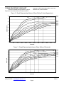
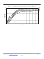
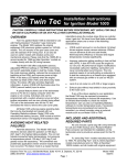
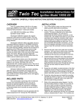
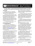
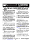
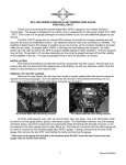
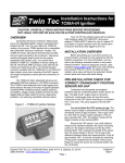
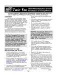
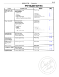
1
Twin Tec Installation Instructions for TC88 Twin Cam Ignition CAUTION: CAREFULLY READ INSTRUCTIONS BEFORE PROCEEDING. NOT LEGAL FOR SALE OR USE IN CALIFORNIA OR ON ANY POLLUTION CONTROLLED VEHICLES. OVERVIEW The Twin Tec TC88 ignition replaces the original equipment (OE) ignition module on 1999-2003 Harley-Davidson motorcycles with carbureted Twin Cam 88 engines. The TC88 offers adjustable advance and adjustable RPM limit settings in 100 RPM increments. Twin Tec PC Link software and an optional USB interface cable (P/N 18014) that connects to the OE data link connector allow the use of a laptop computer to program individual units with a custom advance table and other engine parameters such as rear cylinder timing offset. 3. Install the new Twin Tec module. Figure 1 shows a typical installation under a side cover. You can reuse the original mounting hardware. 4. Reconnect the battery ground cable. OPERATING MODES A single 10 position rotary switch is used to select the operating modes. Switch settings are as follows: 0 Multi-spark disabled 1 Multi-spark enabled 2-7 Not used 8-9 Boot load mode (see text) INSTALLATION 1. Turn off the ignition switch and disconnect the battery ground cable before proceeding. 2. Find and remove the OE ignition module. The OE module is usually located under the seat or under a side cover. You may need to use a small flat screwdriver to press on the connector locking tabs. Figure 1 - Typical Installation We recommend that you use mode switch setting 1 (multi-spark enabled). When multi-spark is enabled, a continuous series of sparks is fired from the advanced timing point until TDC. Most air-cooled engines require relatively cold spark plugs to prevent detonation under high load. Multi-spark reduces the consequent tendency for plug fouling at idle. Switch settings 8-9 are used only for a special "boot load" mode that allows loading an entirely new program into the processor FLASH memory. This would only be done in special circumstances. RECOMMENDED TIMING SETTINGS The Twin Cam 88 engine utilizes a nonadjustable crankshaft position sensor. Thus no mechanical means exist for adjusting the timing. The TC88 module overcomes this limitation. The initial timing switch allows you to shift the entire advance table up or down. Switch setting 5 corresponds to nominal timing. Lower switch settings decrease (retard) the initial timing and higher switch settings increase (advance) the initial timing in one-degree steps. The TC88 module accommodates a wide range of engine applications. The advance slope switch allows you to control the aggressiveness of the ignition advance. Figures 2-4 show the effect of advance slope switch settings. Each figure shows advance curves for various manifold pressure values. Higher switch Daytona Twin Tec LLC, 933 Beville Road, Suite 101-H, S. Daytona, FL 32119 (386) 304-0700 www.daytona-twintec.com Page 1 TC88 5/2015 settings result in more aggressive advance. The effect is more pronounced at high manifold pressures. Note that 30 In-Hg manifold pressure represents wide open throttle (WOT) and 16 In-Hg represents deceleration conditions. Switch setting 5 is similar to the OE advance. Tuning a particular engine setup always requires some trial and error experimentation, but maximum power is usually obtained by using the highest advance settings possible without audible spark knock. Some recommended starting points are given below: For stock engines run on normal pump gas (8789 octane), use initial timing setting 5 and advance slope setting 5. For stock or mildly modified engines run on 92 or higher octane gas, use initial timing setting 5 and advance slope setting 7. For high compression engines, use initial timing setting 2 and advance slope setting 2. If you experience spark knock only at low RPM, you can try reducing the initial timing switch setting while maintaining an aggressive advance slope for maximum power at high RPM by increasing the advance slope switch setting. If spark knock is a problem at high RPM, decrease the advance slope switch setting. Once you have determined the best switch settings, you can further optimize the timing at a particular RPM or manifold pressure by programming a custom advance curve with our PC Link software and optional interface cable. TUNING TIP: Lean air/fuel ratio (AFR) increases the tendency for spark knock. Check AFR and rejet carburetor before optimizing ignition timing. Test the motorcycle on a dyno with an exhaust gas sniffer or use our WEGO. RPM LIMITER SETTING You can set the RPM limit from 3,000 to 9,900 RPM in 100 RPM increments by means of two rotary switches. The RPM limit is X100 switch setting (i.e. 57 = 5,700 RPM). Inadvertent settings below 3,000 RPM are ignored and result in a 3,000 RPM limit. The TC88 module uses a newly developed RPM limiting algorithm that has been highly optimized for odd firing V twin engines. When the engine is held against the RPM limit, cylinder firing is always paired. This eliminates a torque couple and results in very smooth operation compared to random or sequence type RPM limiters. Set a safe RPM limit that is appropriate for your engine. Most Twin Cam 88 engines with OE valvetrain components should not be run over 5,700 RPM. TWIN CAM 88 HOT STARTING PROBLEMS Some Twin Cam 88 engines are prone to hot starting problems. When cranked after a short hot soak, the engine may “kick back.” Over time, this will cause damage to the ring gear and starter pinion. The TC88 module uses an improved starting algorithm that includes a programmable cranking delay. The TC88 module is shipped with a zero cranking delay: it fires on the first recognized compression stroke. This works best on stock and mildly modified engines. High compression engines may exhibit a “dieseling” phenomena after a hot soak. This can be verified by temporarily disconnecting the 3 terminal coil primary connector to disable the ignition. If the engine still kicks back or runs for several revolutions after cranking, the problem is dieseling. The only solution is to install compression releases. When compression releases are installed, best starting results will be obtained by programming the TC88 module for a 1-2 revolution cranking delay. This can be done by means of the PC Link software and optional interface cable. CUSTOM BIKE CONSIDERATIONS You can obtain a wire harness from your local H-D® dealer and you can use the wiring diagram in the H-D® manual. At a minimum, you must hookup the crankshaft position (CKP) sensor, manifold pressure (MAP) sensor, ignition coil, power, and ground. If you have an early Twin Cam 88® engine with the camshaft position (CMP) sensor, you can leave this sensor disconnected. We highly recommend that you leave the H-D® data link plug intact, as it is required for the PC link. If you are not using the stock (or a Twin Cam 88® compatible) instrument cluster, leave the check engine LED wire (black connector, pin 4) unconnected. This signal cannot drive a lamp bulb. The tach signal is at pin 12 on the black connector. The tach signal should drive most aftermarket tachs intended for H-D® applications. If you are not using a bank angle sensor or TSSM module, you must ground the wire Daytona Twin Tec LLC, 933 Beville Road, Suite 101-H, S. Daytona, FL 32119 (386) 304-0700 www.daytona-twintec.com Page 2 TC88 5/2015 going to pin 10 on the black connector. The engine will not start unless you ground this wire. If you making your own wire harness, please note that H-D® wiring diagrams show an incorrect view of the MAP sensor and mating connector. Please refer to the TC88 Tech FAQ on our website. The MAP sensor will be damaged and the engine will not start if the sensor hookup is incorrect. GENERAL RECOMMENDATIONS The TC88 is designed to be used with the H-D OE coil. Twin Cam 88 engines require a coil with primary resistance less than one ohm. All aftermarket coils intended for Twin Cam 88 engine applications have electrical output characteristics similar to the OE coil and do not offer any particular advantage. Due to the short lengths involved on motorcycle applications, energy losses in spark plug wires are insignificant. OE carbon core suppression cables will deteriorate after several years. For a more durable replacement, we suggest spiral core type spark plug cables. CAUTION: Do not use solid copper spark plug cables or non-resistor type spark plugs. The unit may misfire. The TC88 generates a trigger signal that is compatible with the H-D OE tachometer and all aftermarket tachometers intended for Twin Cam 88 applications. Note that the tachometer is not connected to the coil. If your motorcycle was not originally equipped with a tachometer and you need hookup instructions or the tachometer is inoperative, refer to the motorcycle service manual for more information. CHECK ENGINE LED DIAGNOSTICS The TC88 has a diagnostic routine that communicates fault conditions by means of the check engine LED located on the instrument cluster. Please note that the TC88 is not compatible with H-D scan tools that connect to the OE diagnostic link. When the ignition switch is first turned on, the check engine LED illuminates. The LED will remain on until the engine is started. If a diagnostic fault is detected, the LED will flash a number of times and then pause for several seconds. The number of flashes indicates the fault condition as follows: 1 Flash. Crankshaft position (CKP) sensor signal lost. This fault occurs if the engine stalls while the ignition is on. It may also indicate a defective CKP sensor or intermittent wire harness connection. 2 Flashes. Security system (TSSM) or bank angle sensor fault. This fault occurs if the security system (2001 and later models only) is activated or the bank angle sensor indicates a "tipped over" condition. It may also indicate a defective TSSM or bank angle sensor module or intermittent wire harness connection. 3 Flashes. Manifold pressure (MAP) sensor rationality check failure. The MAP sensor signal is outside the expected range. The sensor may be defective or have an intermittent wire harness connection. 4 Flashes. Low battery voltage. This fault warns that the battery is almost totally discharged. The most likely cause is a defective voltage regulator, alternator, or battery. This fault may occur immediately after cranking if the battery is weak but should be cleared within several minutes if the charging system is functioning. 5 Flashes. High battery voltage. The most likely cause is a defective battery or voltage regulator or loose battery connection. PC LINK CABLE AND SOFTWARE The new Twin Tec USB Interface (P/N 18014) provides PC connectivity for all of our engine controls (ignition and fuel injection systems) and eliminates the requirement for multiple cables or a separate USB adapter. Two Windows based programs are available for use with the Twin Tec module: PC Link TC88 for programming custom advance curves and other engine parameters and Operating Statistics for viewing engine operating data. The latest versions of our software are always available for download on our website. The software is free and will work in demo mode without a Twin Tec module attached. Refer to the software documentation for details. The optional USB interface cable connects to the OE data link connector. This is a four terminal Deutsch connector usually found near the ignition module. The PC link can access the TC88 module when the ignition is turned on and the engine has not yet been started. Once the engine is started, the PC link is disabled. Note that no damage occurs if the engine is inadvertently started while the PC link is still attached. Daytona Twin Tec LLC, 933 Beville Road, Suite 101-H, S. Daytona, FL 32119 (386) 304-0700 www.daytona-twintec.com Page 3 TC88 5/2015 TROUBLESHOOTING FLOWCHART Follow the troubleshooting flowchart on page 6. Experience has shown that most units returned for warranty are OK and another problem, such as a defective coil, is later identified. Figure 2 - Graph Representing Advance Slope Setting 0 (Least Aggressive) 45 16 IN-HG 18 IN-HG DECEL 40 20-IN HG 22 IN-HG 24 IN-HG 26 IN-HG 28 IN-HG 30 IN-HG 35 ADVANCE (DEG) 30 25 WOT 20 15 10 5 0 0 500 1000 1500 2000 2500 3000 3500 4000 4500 5000 5500 ENGINE RPM Figure 3 - Graph Representing Advance Slope Setting 5 (Nominal) 45 16 IN-HG 18 IN-HG DECEL 40 20-IN HG 22 IN-HG 24 IN-HG 26 IN-HG 35 28 IN-HG 30 IN-HG ADVANCE (DEG) 30 WOT 25 20 15 10 5 0 0 500 1000 1500 2000 2500 3000 3500 4000 4500 5000 5500 ENGINE RPM Daytona Twin Tec LLC, 933 Beville Road, Suite 101-H, S. Daytona, FL 32119 (386) 304-0700 www.daytona-twintec.com Page 4 TC88 5/2015 Figure 4 - Graph Representing Advance Slope Setting 9 (Most Aggressive) 45 16 IN-HG 18 IN-HG 20-IN HG 22 IN-HG 24 IN-HG 26 IN-HG 28 IN-HG 30 IN-HG DECEL 40 35 WOT ADVANCE (DEG) 30 25 20 15 10 5 0 0 500 1000 1500 2000 2500 3000 3500 4000 4500 5000 5500 ENGINE RPM Daytona Twin Tec LLC, 933 Beville Road, Suite 101-H, S. Daytona, FL 32119 (386) 304-0700 www.daytona-twintec.com Page 5 TC88 5/2015 Troubleshooting Flowchart STARTING POINT FOR CUSTOM BIKE (NO OE MODULE) STARTING POINT (OE MODULE AVAILABLE) REFER TO SECTION ON TSSM/BANK ANGLE AND MAP SENSOR HOOKUP. IS HOOKUP CORRECT? NO REPLACE TC88 WITH OE MODULE OR ANOTHER KNOWN GOOD MODULE. IS PROBLEM FIXED? YES YES REPAIR UNDERLYING PROBLEM BEFORE INSTALLING TC88. REFER TO MOTORCYCLE SERVICE MANUAL REINSTALL TC88 REPAIR HOOKUP NO TURN IGNITION ON. SET ENGINE SWITCH TO RUN. IS CHECK ENGINE LED ILLUMINATED? NO YES CHECK FOR +12V POWER AT MODULE (PIN 1 OF BLACK CONNECTOR). IS +12V POWER OK? YES DOES ENGINE START? NO NO DOES CHECK ENGINE LED FLASH FAULT CODE? REPAIR WIRING PROBLEM. REFER TO MOTORCYCLE SERVICE MANUAL. REPLACE TC88 NO DOES ENGINE STOP OR DROP CYLINDER AFTER SEVERAL MINUTES OF RUNNING? NO REPLACE TC88 NO YES REPLACE COIL. IS PROBLEM FIXED? DOES CHECK ENGINE LED REMAIN ILLUMINATED WHEN ENGINE IS CRANKED? YES NO CHECK CRANKSHAFT POSITION (CKP) SENSOR. REFER TO MOTORCYCLE SERVICE MANUAL. IS SENSOR OK? YES NO REPLACE SENSOR OR REPAIR WIRING. REPLACE TC88 YES DOES ENGINE MISFIRE UNDER LOAD? NO YES NO YES DONE REPLACE TC88 YES REPLACE SPARK PLUGS, SPARK PLUG WIRES, AND COIL IS PROBLEM FIXED? YES NO REPLACE TC88 DOES ENGINE MISFIRE AT PART THROTTLE OR WHILE COLD? NO CORRECT FAULT REPLACE COIL. IS PROBLEM FIXED? NO DONE DONE CHECK FOR LOW BATTERY, NO FUEL, OR FOULED SPARK PLUGS. ANY OBVIOUS FAULT FOUND? YES REFER TO CHECK ENGINE LED DIAGNOSTICS SECTION. FIX APPLICABLE PROBLEM. WAS THE PROBLEM FIXED WHEN AN OE MODULE WAS TRIED IN PLACE OF THE TC88? YES YES FOR MISC PROBLEMS, CALL TECH SUPPPORT. YES CHECK FOR INCORRECT CARB JETTING OR INTAKE LEAK. IS PROBLEM FIXED? NO REPLACE TC88 Daytona Twin Tec LLC, 933 Beville Road, Suite 101-H, S. Daytona, FL 32119 (386) 304-0700 www.daytona-twintec.com Page 6 YES DONE NO REPLACE TC88 TC88 5/2015